
KDTF324PPA - Washing machine KITCHENAID - Free user manual and instructions
Find the device manual for free KDTF324PPA KITCHENAID in PDF.

| Product Type | Built-in Dishwasher |
| Brand | KitchenAid |
| Model | KDTF324PPA |
| Dimensions (required opening) | Height: 820-900 mm, Width: 600 mm min, Depth: 560 mm min |
| Approximate Weight | 75 kg |
| Electrical Supply | 120 V, 60 Hz, 15 A |
| Water Connection | Hot water supply, pressure 20-120 psi, 3/8 in fitting |
| Capacity | Standard (12-14 place settings) |
| Wash Programs | Various programs with options (high temperature, drying, etc.) |
| Integrated Water Softener | Yes, with salt reservoir and automatic regeneration |
| Filter System | Removable filters (upper and lower) |
| Rinse Aid | Recommended, adjustable level |
| Safety | Grounding, anti-tip device, child safety (lockable door) |
| Noise Level | Low, with sound adjustment option |
| Interior Light | Yes (on some models) |
| Floor Display | Optional (depending on model) |
| Maintenance and Cleaning | Exterior cleaning with soft cloth, dishwasher cleaner recommended monthly, vinegar rinse possible |
| Spare Parts and Repairability | Whirlpool certified parts, technical support available |
| Warranty | See Quick Start Guide |
Frequently Asked Questions - KDTF324PPA KITCHENAID
User questions about KDTF324PPA KITCHENAID
0 question about this device. Answer the ones you know or ask your own.
Ask a new question about this device
Download the instructions for your Washing machine in PDF format for free! Find your manual KDTF324PPA - KITCHENAID and take your electronic device back in hand. On this page are published all the documents necessary for the use of your device. KDTF324PPA by KITCHENAID.
USER MANUAL KDTF324PPA KITCHENAID
STAINLESS STEEL TUB DISHWASHER OWNER'S MANUAL
GUIDE D'UTILISATION DU LAVE-VAISSELLE AVEC CUVE EN ACIER INOXYDABLE
Table of Contents/Table des matières
DISHWASHER SAFETY 2
Dishwasher Safety 2
DISHWASHER MAINTENANCE AND CARE 4
User-Maintenance Instructions 4
INSTALLATION REQUIREMENTS....8
Tools and Parts 8
Location Requirements 11
Cabinet Opening Dimensions 11
Drain Requirements 11
Water Supply Requirements.... 11
Electrical Requirements 12
INSTALLATION INSTRUCTIONS 12
Before You Begin.... 13
Prepare Cabinet Opening - New Utilities.... 13
Install Moisture Barrier (Recommended for Wood
Countertops).... 14
Prepare Dishwasher.... 14
Remove Access and Toe Panels 14
Connect Water Line to Fill Valve.... 15
If a Drain Hose Extension is Required ....
Install Door Handle (on some models)
Place Dishwasher in Cabinet.... 16
Custom Panel Installation (on some models)......
Electrical Connection.... 19
Direct Wire Connection 19
Power Cord Connection 20
Junction Box Assembly 20
Final Installation Check 22
Secure Dishwasher in Cabinet Opening.... 23
Choose Anchor Attachment Method.... 25
Connect Water Line to House Shutoff Valve......
Connect Drain Hose 25
Complete Installation 28
Install Access Panel 28
T-Gasket Installation (on some models) 2
Check Operation.... 29
If Dishwasher Does Not Operate 29
Additional Tips.... 29
SÉCURITÉ DU LAVE-VAISSELLE.... 30
Your safety and the safety of others are very important.
We have provided many important safety messages in this manual and on your appliance. Always read and obey all s messages.

This is the safety alert symbol.
This symbol alerts you to potential hazards that can kill or hurt you and others.
All safety messages will follow the safety alert symbol and either the word "DANGER" or "WARNING." The words mean:
DANGER
WARNING
You can be killed or seriously injured if you don't immediately follow instructions.
You can be killed or seriously injured if you don't follow instructions.
All safety messages will tell you what the potential hazard is, tell you how to reduce the chance of injury, and tell you what can happen if the instructions are not followed.
IMPORTANT SAFETY INSTRUCTIONS
WARNING: When using your dishwasher, follow basic precautions, including the following:
-
Read all instructions before using the dishwasher.
■ Use the dishwasher only for its intended function.
■ Use only detergents or wetting agents recommended for use in a dishwasher and keep them out the reach of children.
■ When loading items to be washed: -
Locate sharp items so that they are not likely to dan the door seal; and
-
Load sharp knives with the handles up to reduce the risk of cut-type injuries.
-
Do not wash plastic items unless they are marked "dishwasher safe" or the equivalent. For plastic items not marked, check the manufacturer's recommendations.
■ Do not touch the heating element during or immediately after use.
■ Do not operate your dishwasher unless all enclosure panels are properly in place.
■ Do not tamper with controls.
■ Do not abuse, sit on, or stand on the door or dish racks the dishwasher.
■ To reduce the risk of injury, do not allow children to play or on a dishwasher.
■ Under certain conditions, hydrogen gas may be produced in a hot-water system that has not been used for two weeks or more. HYDROGEN GAS IS EXPLOSIVE. If the hot-water system has not been used for such a period, before using the dishwasher, turn on all hot-water faucets and let the water flow from each for several minutes. This will release any accumulated hydrogen gas. As the gas is not programmable, do not smoke or use an open flame during this time.
■ Remove the door to the washing compartment when removing an old dishwasher from service or discarding it.
■ Do not use replacement parts that have not been recommended by the manufacturer (e.g. parts made at home using a 3D printer).
SAVE THESE INSTRUCTIONS
GROUNDING INSTRUCTIONS
For a grounded, cord-connected appliance:
This appliance must be grounded. In the event of a malfunction or breakdown, grounding will reduce the risk of electric shock by providing a path of least resistance for electric current. The appliance is equipped with a cord having an equipment-grounding conductor and a grounding plug. The plug must be plugged into an appropriate outlet that is installed and grounded in accordance with all local codes and ordinance.
WARNING: Improper connection of the equipment-grounding conductor can result in a risk of electric shock. Check with a qualified electrician or serviceman if you are in doubt as to whether the appliance is properly grounded.
Do not modify the plug provided with the appliance — If it will not fit the outlet, have a proper outlet installed by a qualified electrician.
For a permanently connected appliance:
This appliance must be connected to a grounded metal, permanent wiring system, or an equipment-grounding conductor must be run with the circuit conductors and connected to the equipment-grounding terminal or lead on the appliance.
SAVE THESE INSTRUCTIONS
WARNING

Tip Over Hazard
Do not use dishwasher until completely installed.
Do not push down on open door.
Doing so can result in serious injury or cuts.
DISHWASHER MAINTENANCE AND CARE
User-Maintenance Instructions
Cleaning the Exterior
Clean the exterior of the dishwasher with only a soft, damp and mild detergent. If your dishwasher has a stainless steel exterior, it may have a coating that is resistant to fingerprints. Avoid using abrasive cleaning products on the exterior of the dishwasher.
Cleaning and Maintaining the Interior
Many detergents may leave white spots or a white residue of dishwasher and on the interior of the dishwasher. Over time residue can become unsightly and could affect dishwasher performance. Use of a dishwasher cleaning product such as affresh®+ Dishwasher Cleaner can help to remove the residue. Monthly use of affresh Dishwasher Cleaner is recommended to help maintain the dishwasher. Follow package directions.
Another method to remove white residue is to use a vinegar. However, vinegar is an acid and using it too often could day your dishwasher.
Place (do not pour) 2 cups (500 mL) white vinegar in a dishwasher-safe measuring cup on the bottom rack. Run the dishwasher through a complete washing cycle using an air-oan energy-saving dry option. Do not use detergent. Vinegar mix with the wash water.
NOTE: We recommend the use of high-quality, premeasured detergent tablets or packs and the use of rinse aid for dis cleaning and daily care.
If you have a drain air gap, check and clean it if the dis not draining well.
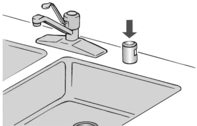
natural_image
Illustration of a kitchen sink with a faucet and a water dispenser, showing a downward arrow indicating a drop (no text or symbols present)To Reduce Risk of Property Damage During Vacation or Extended Time Without Use
■ When you will not be using the dishwasher during the summer months, turn off the water and power supply to the dishwasher.
■ Make sure the water supply lines are protected against freezing conditions. Ice formations in the supply lines can increase water pressure and cause damage to your dishwasher or home. Damage from freezing is not covered the warranty.
■ When storing your dishwasher in the winter, avoid water damage by having your dishwasher winterized by authorized service personnel.
Setting Menu
- Press and hold the "Hi Temp" button for 5 seconds.
- Release "Hi Temp" and press the "Start/Resume" button within 2 seconds. If you do not press Start within 2 seconds, the display will turn off and you will need to start over and go to step 1.
To go to a feature other than Water Hardness Level, press "Normal" button to move to the feature you would like to change (Rinse Aid Level, Sound Level, Light in Tub, Kosher Friendly, Factory Reset). See the table for what is shown of the display to indicate these features.
- Press the "Start/Resume" button to select the feature and enter the sub-menu. The display will change to show the current setting of the feature. (For example, if you selected the Sound Level and you haven't changed it before, then "S1" show).
Press "Normal" button to change the value of the feature setting. (For example, if you want to turn the sound off, then press the "Normal" button and "S0" shows on display model: Press the "Start/Resume" button to confirm the new selection index. The feature setting will not be changed until the Start/Resume" button is pressed.
The dishwasher will return to the Off state when the Start but is pressed.
| inLETTER S will | ETTING(Features varies by model) | VALUES(Default - in bold) |
| shwasher | Water Hardness Level(see “SETTING THE WATER HARDNESS” and “WATER HARDNESS TABLE”) | 0 | 1 | 2 |4 | 5 |
| shwasher is | ||
| Rinse Aid Level(see “ADJUSTING THE DOSAGE OF RINSE AID”) | 0 | 1 | 24 | 5 | 6 | |
| Sound“1” = On, “0” = Off | 1 | 0 | |
| Light in the Tub(on some models)“1” = On, “0” = Off | 1 | 0 | |
| Kosher Friendly mode“1” = On, “0” = Off | 1 | 0 | |
| summer washer. | Display on the floor(on some models)“1” = On, “0” = Off | 1 | 0 |
| ed byed | Factory SettingsPress START/Pause to restore to the factory default all the values of the settings included in the settings menu. | - |
NOTE: Refer to the online Cycle Guide for complete cycle and setting details.
Water Softening System
IMPORTANT: If you have hard water (above 15 grains) and have a whole house water softener, the water softener and heating element may be damaged as a result of limescale accumulation. In such instances of hard water, the water so in the dishwasher should be used.
The water softener reduces water hardness thereby reducing calcium buildup on the heater, inside the dishwasher, and o
dishes. Soft water also allows your detergent to operate most IMPORTANT: Run a cycle every time as soon as you completely efficiently. This system regenerates using salt, so it is necessarying the salt reservoir to avoid corrosion.
to keep the salt reservoir filled. The regeneration process occurs
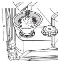
as needed during a cycle to keep the water softener operating Cleaning the Filters
properly. The frequency of regeneration depends on the water is very easy to remove and maintain the filters. The chart h hardness level setting. The water softener system is "OFF" shows the recommended cleaning frequency.
default from the factory, so if the water softener is to be system must be set to "ON" by selecting a water hardness using setting menu. See water hardness setting table.
Water Hardness Setting
Determine your water hardness by obtaining information from water quality report from your water supplier or purchase a hardness test kit at a hardware store.
The water softening system is turned off from the factory (hardness setting "0"). To turn on your water softener, you set the water hardness level in the "SETTING MENU" using a hardness setting value from the following "WATER HARDNESS TABLE". Once the system is turned on, the salt reservoir filled with special dishwasher softener salt and water.
| Water Hardness Table | ||
| Level Grains per gallon (gpg) | Parts per million (ppm) | |
| 0 | Water softener off (factory setting) | |
| 1 | 0-6 0-100 | |
| 2 | 6-12 100-200 | |
| 3 | 12-18 200-300 | |
| 4 | 18-36 300-600 | |
| 5 | >36 >600 | |
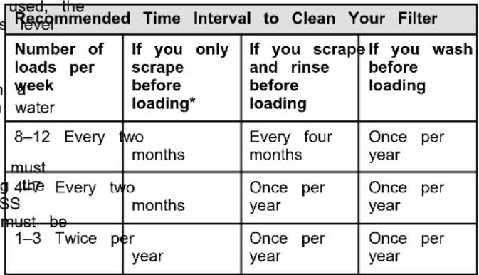
Filling The Salt Reservoir
The salt reservoir is located in the lower part of the dishwasher (under the lower rack on the left side). Once your water is clean the filters as shown.
(under the lower rack on the left side). Once your water softer system is turned on, you must fill the reservoir with dishwasher softener salt and water. As the salt supply is used up with successive system regenerations, a low-salt indicator will light on the control panel indicating it's time to refill the salt. Once salt refilled, the light will turn off.
-
Remove the lower rack and unscrew the reservoir cap (by turning the cap counter-clockwise).
-
Position a funnel (comes along with your dishwasher) and fill the salt reservoir right up to its edge (approximately 0.5 kg); it is not unusual for a little water to leak out.
-
If filling the reservoir for the first time, it is also necessary that the reservoir with water after filling with salt. When refilling the salt, there is no need to add more water.
-
Remove the funnel and wipe any salt residue away from the opening. Make sure the cap is screwed on tightly so that detergent or food can get into the reservoir during the dishwasher use (this could damage the water softener beyond repair).
IMPORTANT: Run a cycle every time as soon as you complete, resulting in the salt reservoir to avoid corrosion.
Cleaning the Filters
 |
*Manufacturer's recommendation: This practice will conserve the water and energy that you would have used to prepare your dishes. This will also save you time and effort.
Very Hard Water
If you have hard water (above 15 grains) and you do not have whole house water softener system, be sure to turn on and use the water softener in the dishwasher. Also clean your filter at once per month. Building up of white residue on your dishwash indicates hard water. For tips on removing spots and stains, see the online "Troubleshooting" section.
NOTE: Online references can be found in the Quick Start Guid
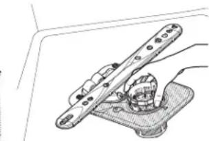
Filter Removal Instructions
- Turn the upper filter assembly 1/4 turn counterclockwise and lift out.
- Separate the upper filter assembly by gently pulling apart.
washer Clean the filters as shown.
softener
asher
ashner
th
t on
The image is too blurry to recognize any text content.
salt
6
D
(by
(by
m = 311
- C'U
nd fill
5 ka)
Kg)
[Non-Text]
[Non-Text]
[Non-Text]
[Non-Text]
[Non-Text]
[Non-Text]
[Non-Text]
[Non-Text]
[Non-Text]
[Non-Text]
[Non-Text]
[Non-Text]
[Non-Text]
[Non-Text]
[Non-Text]
[Non-Text]
[Non-Text]
[Non-Text]
[Non-Text]
[Non-Text]
[Non-Text]
[Non-Text]
[Non-Text]
[Non-Text]
[Non-Text]
[Non-Text]
[Non-Text]
[Non-Text]
[Non-Text]
[Non-Text]
[Non-Text]
[Non-Text]
[Non-Text]
[Non-Text]
[Non-Text]
[Non-Text]
[Non-Text]
[Non-Text]
[Non-Text]
[Non-Text]
[Non-Text]
[Non-Text]
[Non-Text]
[Non-Text]
[Non-Text]
[Non-Text]
[Non-Text]
[Non-Text]
[Non-Text]
[Non-Text]
[Non-Text]
natural_image
Line drawing of a cooking step with a bowl containing granular material and a side pot (no text or symbols)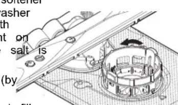
natural_image
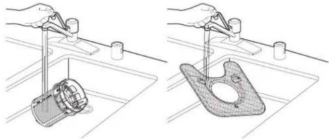
Technical line drawing of a mechanical clamp or bracket assembly (no text or symbols)Cleaning Instructions
IMPORTANT: Do not use wire brush, scouring pad, etc., as they may damage the filters.
Rinse filter under running water until most soils are removed scanning the QR code: you have hard-to-remove soils or calcium deposits from hard water, a soft brush may be required.

natural_image
Two technical illustrations showing hands using a tool to clean a mechanical component on a sink (no text or symbols present)Error Codes/Blinking Lights
| Issue Code | Shown(7 Seg Display)(if present) | Code Shown on Front Panel LED *(# blinks, Pause, # blinks) | What will happen? | What to do? |
| Dishwasher fails to operate fill valve correctly | F1E1/F1E5 | Pause 1Pause - pause, repeat | Drain sequence will begin, machine operation will be prevented. | Turn off water to unit (if possible).Turn off power unit. If the water cannot be turned off, DO No off power and keep door closed. Press Cancel one time to silence alarm tone. Call service. |
| Motor controller failure | F1E2 1 Pause | Pause 2Pause, repeat | Cycle ends. Call service. | |
| No water present at dishwasher | H2O 8 Pause | Pause 1Pause - pause, repeat | Cycle is paused. Ensure fill hose is connected to product. Ensure w supply is turned ON. Press Start to resume c alarm still present, call service. | |
| User interface service communication fault | F6E1 6 Pause | Pause 1Pause - pause, repeat | Product will not able start or resume cycles. | Call service. |
| Wash motor failure | F7E2 7 Pause | Pause 1Pause, repeat/7Pause 2 Pause, repeat | Cycle ends. Call service. | |
| Sensor detects water left in the sump | F7E3 7 Pause | Pause, 3Pause - pause, repeat | Cycle ends. Call service. | |
| Dishwasher overfills | F8E4 8 Pause | 4Pause - pause, repeat | Drain sequence will begin, machine operation will be prevented. | For Professional InstallersTurn off water to unit (if possible). Turn off power to unit. If the water cannot be turned off, DO NOT turn off power and keep door closed. Press Cancel key one time to silence alarm tone. Call service.For Self Installers■ Press CANCEL button twice or cycle power. This may clear the issue.■ Check to see if the wire connector is connected to the float switch on the drip tray. If the wire is of reconnect and then hit the cancel button twice.■ Check to see if there is any water in the drip tra water is in the drip tray, remove the water and reinstall the drip tray. Make sure to connect the wiring to the float. Check to see where water may have leaked into the drip tray (Check the water inlet fittings to see if they are leaking).■ If water was in the tray and no leaks were found, run the product on the shortest installation cycle while checking for leaks. The access panel should be off to observe any leaks.■ If problem still exists, call for service. |
| Fill valve stuck on | F8E5 8 Pause | 5Pause - pause, repeat | Drain sequence will begin, machine operation will be prevented. | Turn off water to unit (if possible).Turn off power to unit. If the water cannot be turned off, DO NOT turn off power and keep door closed. Press Cancel key one time to silence alarm tone. Call service. |
| Dishwasher will not drain | F9E1 9 Pause | 1Pause - pause, repeat | Cycle ends. If drain | hose is connected to a garbage disposal, confirm that drain hose is not clogged and disposal plug has been knocked out. If unit still will not drain, call service. |
| Variable Speed Drain Motor Fault- Locked Rotor Not Primed | F9E3 9 Pause | 3Pause - pause, repeat | Cycle ends. Call service. |
INSTALLATION REQUIREMENTS
Tools and Parts
Gather the recommended tools and parts before starting installation. Read and follow the instructions provided with tools listed here.
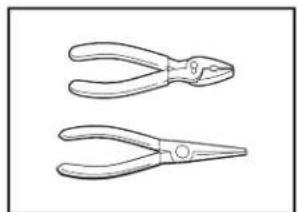
Tools Needed:
natural_image
Two line drawings of pliers with no text or symbols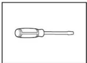
natural_image
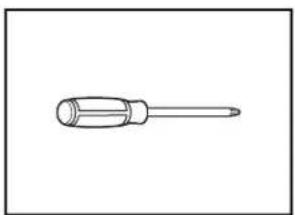
Line drawing of a screwdriver with a cylindrical head and threaded shaft (no text or symbols)Pliers Flat-blade screwdriver
natural_image
Simple line drawing of a screwdriver (no text or symbols)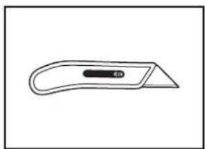
natural_image
Simple line drawing of a flat tool with a handle and central slot (no text or symbols)2 Phillips screwdriver Utility knife
natural_image
Simple line drawing of a screwdriver with a handle and shaft (no text or symbols)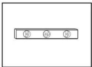
natural_image
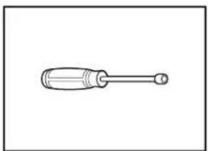
Simple diagram of three circular symbols inside a rectangular box (no text or labels)5/16" (8 mm) and 1/4" Small level (6.35 mm) nut drivers or hex sockets
natural_image
Simple line drawing of a tape measure (no text or symbols)
natural_image
Line drawing of a pair of eyeglasses (no text or symbols)Measuring tape
natural_image
Line drawing of an adjustable wrench with a screw handle (no text or symbols)Safety Glasses
natural_image
Simple line drawing of a dropper or pipette (no text or symbols)10" (254 mm) adjustable wrench that opens to 1 (29 mm)
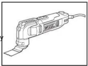
natural_image
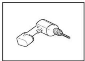
Line drawing of a handheld electric tool with a curved handle and cable (no text or symbols)Oscillating Tool Sand paper
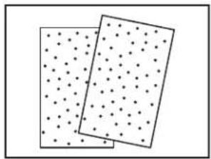
natural_image
Two rectangular panels with dot patterns, no text or symbols present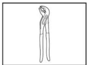
natural_image
Line drawing of a pair of pliers (no text or symbols)Pliers
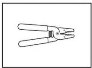
natural_image
Line drawing of a pair of pliers with metal handles and a threaded handle (no text or symbols)Wire strippers
natural_image
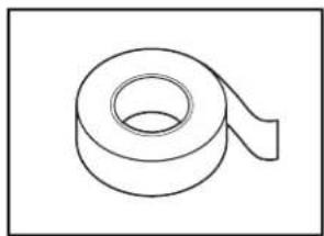
Line drawing of a handheld electric drill bit (no text or symbols)With _2 " (38 mm) Forstner Double sided adhesive
natural_image
Simple line drawing of a rolled-up adhesive tape (no text or symbols)Drill Bit, 3/4" (19 mm) Forstner
Drill Bit, and 1/16" (2.38 mm)
Drill Bit, 3/4"-2" (45-50 mm)
Forstner Drill Bit
natural_image
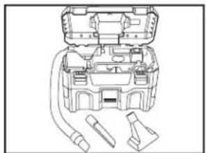
Line drawing of a mechanical device with internal components and connectors (no text or symbols)Portable vacuum cleaner
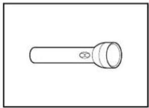
Other Useful Items You May Need:
natural_image
Simple line drawing of a flashlight with a bulb and handle (no text or symbols)Flashlight
natural_image
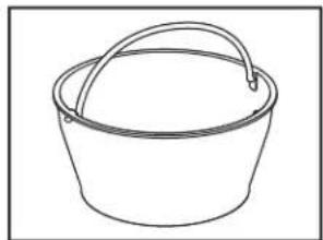
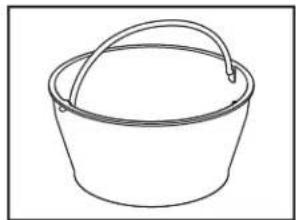
Simple line drawing of a bucket with a handle (no text or symbols)Bucket or Shallow pan
natural_image
Simple line drawing of a folded paper or tape (no text or symbols)Bath towel
natural_image
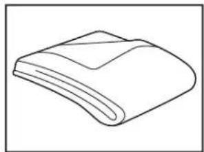
Simple line drawing of a folded or curled object with no text or symbolsMoving blanket
natural_image
Simple line drawing of a rolled-up sheet or cushion on a flat surface (no text or symbols)Floor protector Laser level
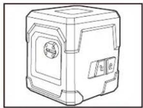
natural_image
Line drawing of a 3D mechanical device with no visible text or symbols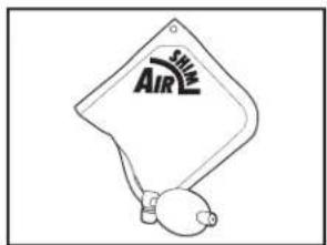
Air shim (3)
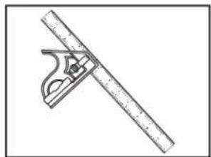
natural_image
Illustration of a protractor and ruler tool (no text or symbols)Combination square
Parts Supplied:
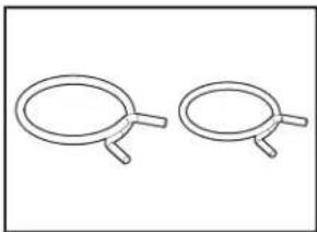
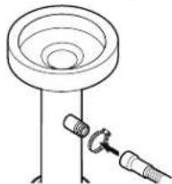
natural_image
Two identical wire handles with handles, shown in side profile (no text or symbols)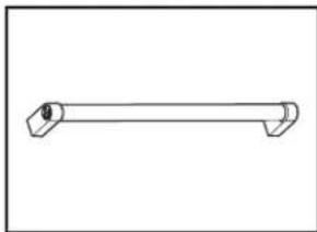
natural_image
Simple line drawing of a horizontal cylindrical object with two protruding ends (no text or symbols)Drain hose clamps (2) One Door handle (on some models) Large (Black) and One Small (Silver)
natural_image
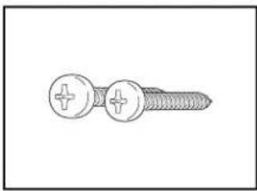
Line drawing of a screw with two circular fasteners and a plus button (no text or symbols)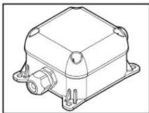
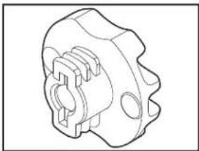
natural_image
Technical line drawing of a mechanical device with mounting flanges and a central housing (no text or symbols)3.5 mm x 18 mm Phillips screw (2)
head Junction box
natural_image
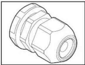
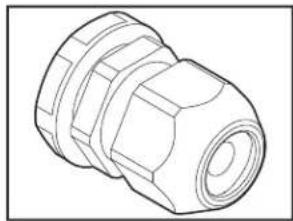
Technical line drawing of a mechanical connector (no text or symbols)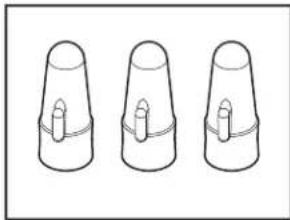
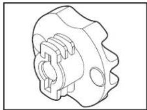
natural_image
Three identical 3D-rendered cylindrical objects with central holes, shown in isometric view (no text or symbols)Cable fittings (2) inside the Wire nuts (3) inside the junction junction box box
natural_image
Technical line drawing of a mechanical component with no visible text or symbols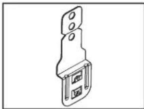
natural_image
Technical line drawing of a mechanical bracket or mounting bracket (no text or symbols)Plastic thick spacers (4) Metal brackets (4)
natural_image
Pure technical line drawing of a diagonal bracket (no text or symbols)
natural_image
Line drawing of a screw with threaded shaft and circular head (no text or symbols)Side gap covers (2) #4 x 38 mm screws (4) for Panel ready mount
natural_image
Line drawing of a mechanical connector or tool with threaded ends and a flanged shaft (no text or symbols)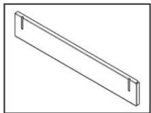
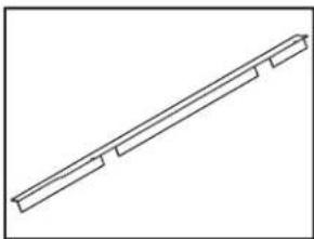
natural_image
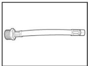
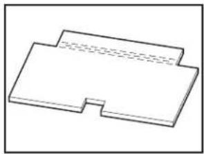
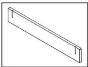
Simple line drawing of a rectangular metal beam with two side notches (no text or symbols)Water Inlet Adapter for hoseAdditional/tall Toe Panel with Leak Detection System shipped uninstalled at the back (on some models) of the dishwasher.
natural_image
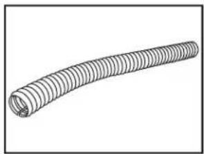
Line drawing of a coiled, ribbed wire or filament (no text or symbols)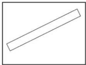
natural_image
Simple geometric shape: a diagonal line inside a rectangle (no text or symbols)Cabinet Grommet (corrugated Moisture Barrier Tape
tubing)
For 12 " (38 mm) hole in cabinet
NOTE: Required for metal cabinets.
NOTE: Moisture barrier tape is recommended if installing a dishwasher under a wooden countertop.

natural_image
Line drawing of a screw with threaded shaft (no text or symbols)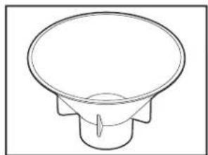
natural_image
Simple line drawing of a conical speaker or speaker with no text or symbols3.5 x 18 mm screws (4)
Cabinet mount
Salt funnel
natural_image
Simple line drawing of a rectangular object with a notch, no text or symbols present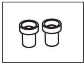
natural_image
Two identical cylindrical mechanical components with flanges, shown in black line drawing (no text or symbols)Floor insulation (on some models)
Studs (on some models)
natural_image
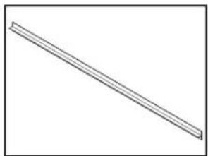
Simple line drawing of a diagonal line with no text or symbolsT-Gasket (on some models)
Make sure all these parts are included in the literature package.
Optional Accessory Parts Available:
Call us at our toll-free number or visit our website listed on tl Quick Start Guide for optional accessory part information.
First-Time Installations
Check local codes. Check existing electrical supply. See the "Electrical Requirements" section. It is recommended that electrical connections be made by a licensed electrical installer.
Additional Parts Needed (not provided):
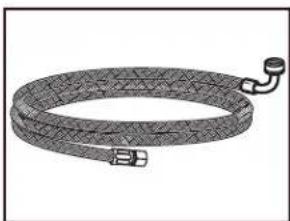
natural_image
Illustration of a coiled cable or hose with connectors (no text or symbols)3/8" (9.5 mm) to 3/4" (19 mm) elbow fitting adapter with inlet hose
Whirlpool Part Number, W10278635RP, 6 ft (1.8 m) inlet hose
Whirlpool Part Number, 8212486, 12ft (3.6 m) inlet hose
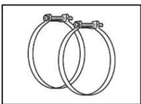
natural_image
Two interlocked circular hoses with metal clips (no text or symbols)Screw-Type Clamps
1^1/2 -2" (38 mm-50 mm) (3 maximum)
NOTE: Be sure to purchase only Whirlpool factory-certified parts and accessories for your appliance. Your installation may require additional parts. To order, refer to the contact information referenced in your Quick Start Guide.
For Power Cord
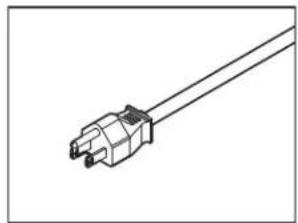
natural_image
Line drawing of a mechanical connector or terminal with a central connector (no text or symbols)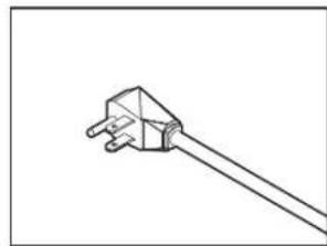
natural_image
Simple line drawing of a plug with two pins, no text or symbols presentPower Cord Kit
Kit typically includes power cord (Cord Kit - Straight: Whirlpool Part Number W11670634, Right Angle: Whirlpool Part Number W11645183), Cable fitting.
NOTE: The Cord Kit - Straight: Whirlpool Part Number W11670634 is recommended for most installations.
For proper installation, refer to the installation instructions provided with the kit.
NOTE: Be sure to purchase only Whirlpool factory-certified parts and accessories for your appliance. Your installation may require additional parts. To order, refer to the contact information referenced in your Quick Start Guide.
Location Requirements
Dishwasher must be fully enclosed (top, sides, back, and upon installation.
An optional moisture barrier accessory is also available for installing underneath a wooden countertop.
Check location where dishwasher will be installed. The location must provide:
■ Convenient access for loading and unloading dishes. Corner locations require a 2" (51 mm) minimum clearance between the side of the dishwasher door and the wall or cabinet.
■ Easy access to water, electricity, and drain:
- Grounded electrical supply is required.
- This dishwasher has a water-heating feature and also requires a connection to a hot water supply line.
- Make sure pipes, wires, and drain hose are within the shaded area shown in the "Cabinet Opening Dimension" section.
- Do not run drain lines, water lines, or electrical wiring they can interfere with or contact dishwasher legs.
- Shelter dishwasher and water lines leading to dishwasher against freezing. Damage from freezing is not covered by the warranty.
NOTE: If dishwasher will be left unused for a period or in a location where it may be subject to freezing, winterized by authorized service personnel.
■ A square opening for proper operation and appearance.
■ The cabinet front to be perpendicular to floor.
■ A level floor.
Helpful Hint: If floor at front of opening is not level with floor at rear of opening, shims may be used to level dishwasher. Optional alignment method using a laser square; review the product help videos.
NOTE: To avoid shifting during dishwasher operation, shims be securely attached to the floor.
■ Do not install dishwasher over carpeted flooring.
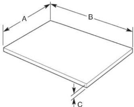
Cabinet Opening Dimensions
Clearances
Check that all surfaces have no protrusions that would pro dishwasher installation.
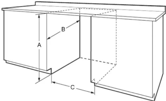
A. 32^5/16 "-35 ^5/16 " (820-900 mm) measured from the lowest point on the underside of the countertop.
B. 22 116 " (560 mm) Minimum
C. 23 ^5/8 " (600 mm) Minimum, measured from narrowest point of opening.
Drain Requirements
A new drain hose is supplied with your dishwasher. If drain hose is not long enough, use a drain hose extension with maximum length of 12 ft (3.7 m).
■ Make sure to connect drain hose to waste tee or disposer above drain trap in house plumbing and 20" (508 mm) minimum above the floor. It is recommended that the drain hose either be looped up and securely fastened to the underside of the counter or be connected to an air gap.
IMPORTANT: This product is not equipped with a high loop on side of the dishwasher. The installer is responsible for adding a high loop in the adjacent cabinet. A high loop is required if the dishwasher will drain into a floor drain. This prevents water drain off from the dishwasher during operation. When the drain is connected to a sink drain, counter-top air-gap or disposer, the high loop is generally not required. An check valve internal to drain prevents back-flow into the dishwasher.
■ Make sure to use an air gap if the drain hose is connected where plumbing lower than 20" (508 mm) above subfloor or floor.
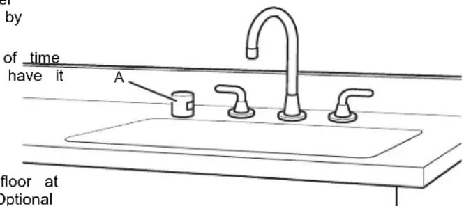
A. Air gap
If required, the air gap should be installed in accordance with the air gap installation instructions. When you are connecting the air gap, a rubber hose (not provided) will be needed to connect to the waste tee or disposer inlet.
■ Use 1/2" (12.7 mm) minimum I.D. drain line fittings.
Water Supply Requirements
This dishwasher may be fitted with a smart inlet hose with a water cut off valve. Do not cut the water inlet hose for an reason, to install, adapt or shorten.
■ This dishwasher has a water heating feature and also requires a connection to a hot water supply line.
■ A hot water line with 20 psi to 120 psi (138 kPa to 827 water pressure can be verified by a licensed plumber.
■ 120°F (49°C) water at dishwasher
■ 3/8" (9.5 mm) O.D. tubing with compression fitting or flexible braided or non braided water supply line.
■ Included water inlet hose with Leak Detection System for son models.
■ Included 3/8" (9.5 mm) Compression x 3/4" (19 mm) Water inlet adapter (only for models with Leak Detection System).
If installed in new construction, make sure the house water supply lines have been flushed prior to connecting the dishwasher to remove any debris that may exist in the supply line.
Electrical Requirements
Be sure that the electrical connection and wire size are ad and in conformance with the National Electrical Code, ANSI/NFPA 70 - latest edition, and all local codes and ord For a fee, a copy of the above code standards can be o from:
National Fire Protection Association
1 Batterymarch Park
Quincy, MA 02169-7471
You Must Have:
■ 120 V, 60 Hz, AC-only, 15 A or 20 A, fused electrical
■ Copper wire only.
■ A maximum of 2 field wiring supply conductors (12 AWG largest size) plus 1 grounding conductor are permitted in terminal box.
■ An included junction box for electrical connection.
We Recommend:
■ Install the dishwasher on a circuit with appropriate interrupt per your local code. The dishwasher is compatible with the delay fuses, standard circuit breakers, and GFCI and AFCI circuit breakers.
Circuit Requirement:
■ The dishwasher may be installed on the same circuit as a garbage disposal providing that the branch circuit cannot exceed rated circuit load and must comply with all governing codes and regulations such as but not limited to National Electrical Code, ANSI/NFPA 70 - latest edition.
■ No electrical connections other than the dishwasher power and ground connections can be made inside of the dishwasher junction box.
If Connecting Dishwasher with a Power Cord:
■ Use a UL-listed power cord kit marked for use with dishwasher. See the "Tools and Parts" section for part details.
■ Plug into a grounded 3-prong outlet. Outlet must meet all local codes and ordinances.
If Connecting Dishwasher with Direct Wiring:
■ Use flexible, armored, or nonmetallic sheathed copper wire with grounding wire that meets the wiring requirements for your home and local codes and ordinances.
■ Use only the supplied plastic cable fittings for flexible and non-metallic sheathed wiring (Romex, etc.). Do not use metallic strain reliefs for these wire constructions.
■ Use a UL-listed/CSA-approved metallic strain relief for armored cable installations (21 mm diameter) if using armored cable. Install the strain relief per the strain relief manufacturer's installation instructions.
■ Use a UL-listed/CSA-approved metallic strain relief for flex metal conduit installations if using flexible metal conduit. In the strain relief per the strain relief manufacturer's install instructions.
INSTALLATION INSTRUCTIONS
WARNING

supply.
Tip Over Hazard
Do not use dishwasher until completely installed.
theo not push down on open door.
Doing so can result in serious injury or cuts.
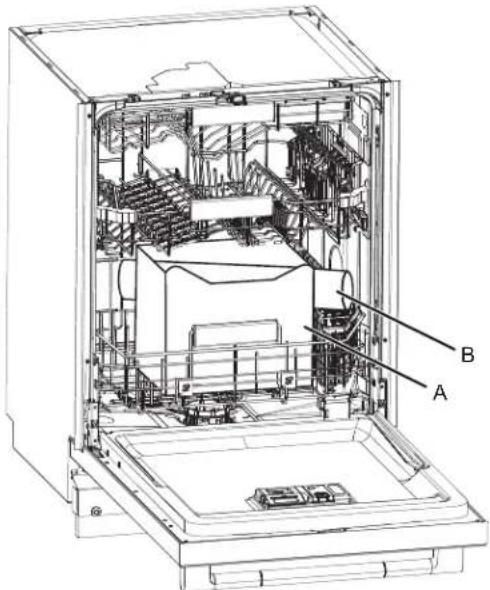
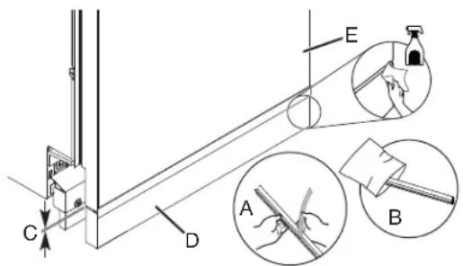
You Need To:
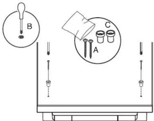
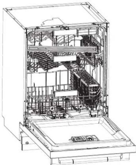
Slowly open the dishwasher door while someone grasps the rear of the dishwasher. Remove shipping materials. Place included parts and literature aside in a safe place for later. Close dishwasher door until latched.
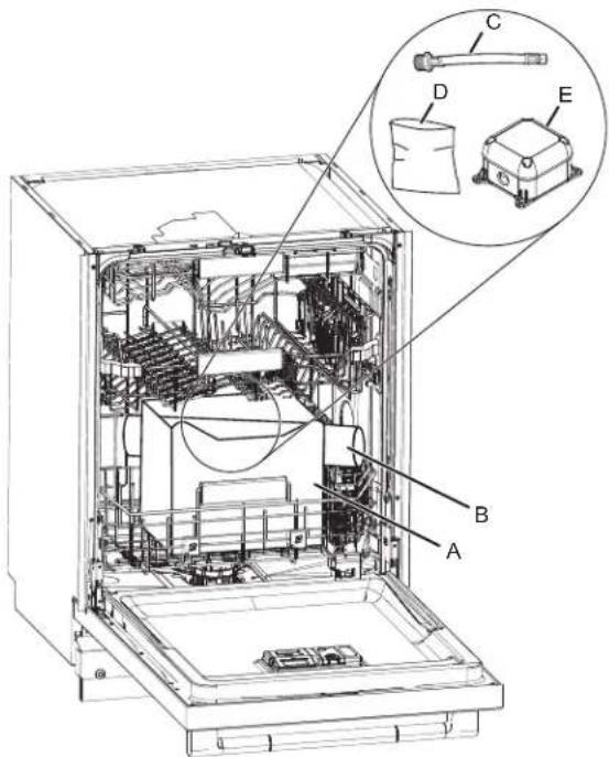
A. Cardboard box containing the Accessories
B. Cardboard tube containing the Handle (on some models)
C. 3/8" to 3/4" (9.5 mm to 19 mm) Water Inlet Adapter
D. Assembly accessories
E. Junction box
IMPORTANT: Do not throw away the Cardboard box. It contains installation materials inside.
NOTE: Each dishwasher is tested at the factory and may contain some residual water in the tub as a result of the t
■eObserve all governing codes and ordinances.
Install this dishwasher as specified in these instructions.
The dishwasher must be installed to meet all electrical and plumbing national and local codes and ordinances.
■ Be sure when installing or moving the appliance that the power cord is not kinked or damaged. Drill hole locations for Water Supply and Drain hose (Optional hole type)
WARNING: To reduce the risk of electric shock, fire or injury to persons, the installer must ensure that the dishwasher is completely enclosed at the time of installation.
Before You Begin
WARNING

Electrical Shock Hazard
Disconnect electrical power at the fuse box or circuit breaker box before installing appliance.
Failure to do so can result in death or electrical shock.
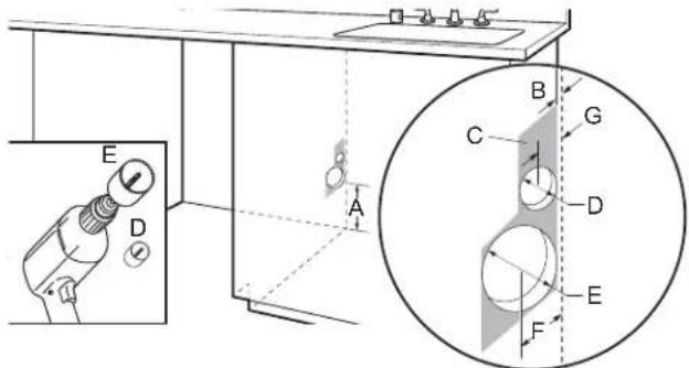
A. 6" (152 mm), minimum height of allowable area from bottom for utility connections.
B. 1/2" (12.7 mm), Thickness of back cabinet wall.
C. 3^1/2 " width x 6" height (88.9 x 152.4 mm), Allowable area for utility connections.
D. 1 ^1/2 " (38.1 mm), Diameter for drain hose hole.
E. 3 ^1/2 " (88.9 mm), Diameter for water supply hose hole.
F. 2 ^1/4 " (57.1 mm), Distance between center of water supply hose hole to the back of the cabinet wall.
G. 1 ^1/4 " (31.7 mm), Distance between center of Drain hose hole to the back of the cabinet wall.
1. Disconnect power
Disconnect electrical power at the fuse box or circuit box before installing dishwasher.
2. Shut off water supply
Shut off water supply to the dishwasher.
Prepare Cabinet Opening – New Utilities
NOTE: The electric and water holes may or may not be on the same cabinet wall. It will depend on the location of water and electric connections.
3. Drill hole location for Water Supply and Drain hose (Preferred hole type)
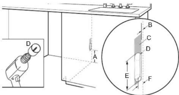
A. 6" (152 mm), minimum height of allowable area from bottom for utility connections.
B. 1/2" (12.7 mm), Thickness of back cabinet wall.
C. 2 ^1/4 " width x ^16 " height (57.20 x 154.40 mm), Allowable area for utility connections.
D. 1 ^3/4 " (44.4 mm), Diameter of Oval hole for water supply and drain hose.
E. 3^3/_4 " (95.3 mm), Height of Oval hole for water supply and drain hose.
F. 2 ^1/4 " (57.1 mm), Distance between center of Oval hole to the back of the cabinet wall.
Drill location for Electrical conduit hole
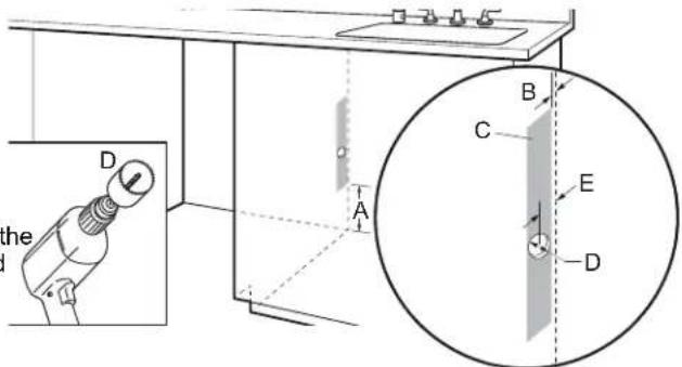
A. 6" (152 mm), minimum height of allowable area from bottom for utility connections.
B. 1/2" (12.7 mm), Thickness of back cabinet wall.
C. 1 ^1/2 " width x 12" height (38.1 x 304.8 mm), Allowable area for utility connections.
D. 1 ^1/2 " (38.1 mm), Diameter for Electrical conduit hole.
E. 1 ^1/4 " (31.7 mm), Distance between center of Electrical conduit hole to the back of the cabinet wall.
6. Sand holes smooth
A. Wood cabinet
B. Metal cabinet
Wood cabinet: Sand the hole until smooth.
Metal cabinet: Cover edges of hole with grommet (corrugated tubing) included with installation materials inside the dishwasher. Cut length to match hole perimeter.
Install Moisture Barrier (Recommended for Wood Countertops)
Moisture barrier/Wood shims
A. Install wood shims
B. Moisture barrier
Make sure the area under the countertop is clean and dry for installation of the moisture barrier. Remove the backing of the
moisture barrier and apply to underside of the countertop along using a 1/4" (6.35 mm) nut driver or Phillips screwdriver, remove 4 screws attaching Access panel to dishwasher.
required.
NOTE: Install wood shims if side anchoring and the gap between sides of the dishwasher are greater than 1/2" (12.7 mm) on each side or are greater than the length of the anchor screws.
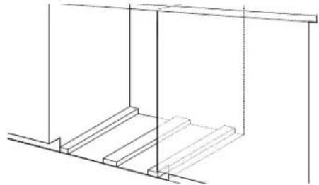
7. Built-up floors - add shims as needed
natural_image
Pure technical line drawing of a structural frame with no text, numbers, or symbolsBuilt-up floors: If the kitchen floor is higher than the cabinet opening's floor—for example, the kitchen floor tile does not extend into the cabinet opening—add shims, as needed, in the area shown to bring the dishwasher up to 34" (864 mm) below the countertop.
NOTE: Shims must be securely attached to floor to avoid movement when the dishwasher is in use.
Prepare Dishwasher
WARNING

Tip Over Hazard
Do not use dishwasher until completely installed.
Do not push down on open door.
Doing so can result in serious injury or cuts.
WARNING
Excessive Weight Hazard
Use two or more people to move and install or uninstall appliance.
Failure to do so can result in back or other injury.
Remove Access and Toe Panels
8. Access panel
natural_image
Technical line drawing of a mechanical bracket assembly with dimension arrows (no text or symbols)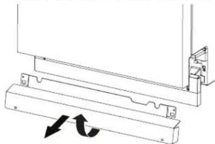
natural_image
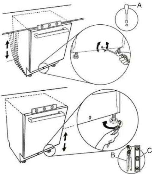
Technical line drawing of a mechanical assembly with two arrows indicating rotational motion (no text or symbols)Slowly lift and remove the Access panel from the hooks of dishwasher.
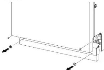
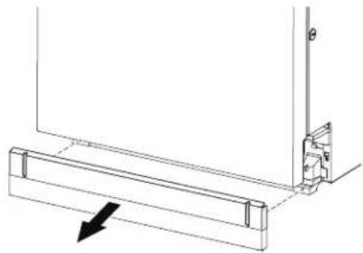
- Toe panel
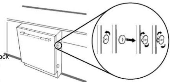
natural_image
Technical line drawing of a mechanical bracket with an arrow indicating direction (no text or symbols)After removing the access panel remove the toe panel.
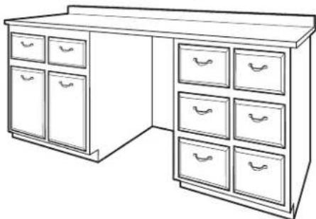
- Measure cabinet opening
natural_image
Line drawing of a standard office desk with multiple drawers (no text or symbols)There is a leveling system on the front of the base carrie. Once the dishwasher is within the cabinet space, use the leveling adjuster to adjust the dishwasher up to the height the cabinet.
Adjust both front and back leveling legs to the same
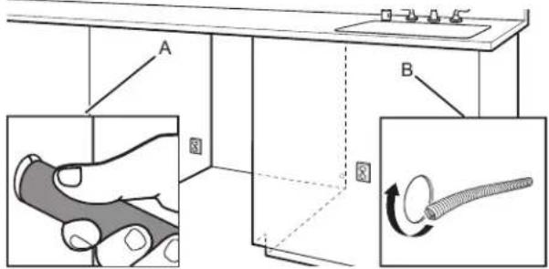
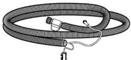
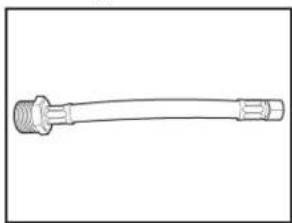
Connect Water Line to Fill Valve
The dishwasher may come with the inlet hose already attached with a threaded connection. It needs to be connected to the inlet end on the house connection.
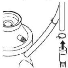
- Leak Detection System Hose (on some models)
natural_image
Illustration of a coiled hose with connectors and a small attached component (no text or symbols)Use the Leak Detection System hose with included 3/8" (9.5 mm) to 3/4" (19 mm) water inlet adapter.
- Add 3/8" (9.5 mm) to 3/4" (19 mm) water inl adapter to the Leak Detection System Hose (on some models)
natural_image
Line drawing of a mechanical connector or tool with threaded ends and flanges (no text or symbols)Connect the 3/8" (9.5 mm) compression fitting of the water inlet adapter to the water supply line and attach the 3/4" (19 mm) connection to the Leak Detection System hose.
- Accessory inlet hose

natural_image
Illustration of a coiled flexible hose with connectors (no text or symbols)See the "Tools and Parts" section at the front of the guid part details and order. Connect the 3/8" (9.5 mm) compression fitting to the water supply line and Attach the 3/4" (19 mm) elbow fitting connection to the dishwasher facing upward as shown above. Confirm the flexible braided for non braided line is long enough to reach the house wall connection. If the hose is not long enough, have a plumber install a supply valve closer to the dishwasher.
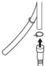
Height a Drain Hose Extension is Required
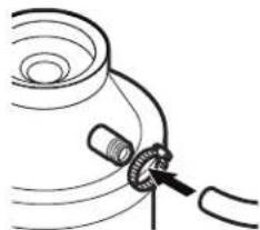
- Slide clamp onto connector

A. Silver clamp
B. Rubber drain hose connector
C. Stop
D. Drain hose stop
E. Drain hose
Using pliers, squeeze open the silver drain hose clamp, an slide it onto the connector between stops.
Install Door Handle (on some models)
15. Install Door Handle
A. Cardboard box containing the Accessories
B. Cardboard tube containing the Door Handle (on some models)
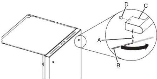
A. Setscrew (in the bottom of the handle)
B. Hex key
C. Handle
D. Mounting stud
IMPORTANT: Do not scratch the front panel during this procedure. If door panel has a protective film, peel film back past the point of the handle studs before installing handle. Handle is easiest to install while unit is on its back.
Remove the door handle and hex key from the packaging. Setscrews are already installed in the handle. Place handle on mounting studs with the setscrews facing towards the bottom of dishwasher. Push the door handle tightly against the door. Insert the short end of the hex key into the setscrews. Tighten the setscrews 1/4 turn past snug.
Retain hex key with Owner's Manual.
Place Dishwasher in Cabinet
Refer to the section "Electrical Connection" in this Owner's Manual for connecting to the power supply before placing the dishwasher in the cabinet.
WARNING
Excessive Weight Hazard
Use two or more people to move and install or uninstall appliance.
Failure to do so can result in back or other injury.
NOTE: Route water supply, drain hose, and power cord out the rear of the dishwasher.
16. Move dishwasher close to cabinet opening
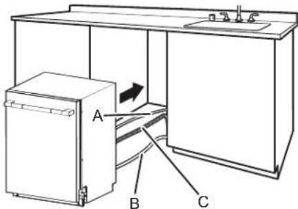
A. Water line
C. Drain hose
B. Junction box cable
Route the utilities through the holes in the cabinet and pu the slack out at the same time as the dishwasher is push into the cabinet.
NOTE: Route electrical lines only through the electrical conduit hole that was previously sanded or protected by a grommet.
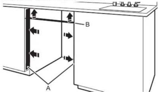
17. Adjust side spacers
Measure the top and bottom width of opening of the frame less cabinet. Remove and adjust the 4 included dishwasher spacers, by turning 90 degrees, and removing with a slotte screwdriver. Each spacer has 3 positions.
NOTE: If the cabinets are not frame less, additional spacer will be required (included) and need to be applied by the installer.
| Types of Cabinets Types of Attachment |
| Frame less cabinets Plastic spacers |
| Face frame cabinets Metal brackets |
See section "Secure Dishwasher in Cabinet Opening" in this Owner's Manual for Securing dishwasher with different types of cabinets.
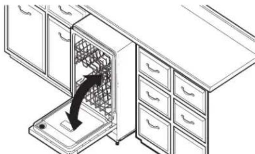
- Move Dishwasher into final position
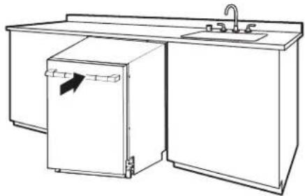
natural_image
Line drawing of a kitchen sink with a refrigerator and faucet (no text or symbols)- Place foam insulation pad below the dishwasher (on some models)
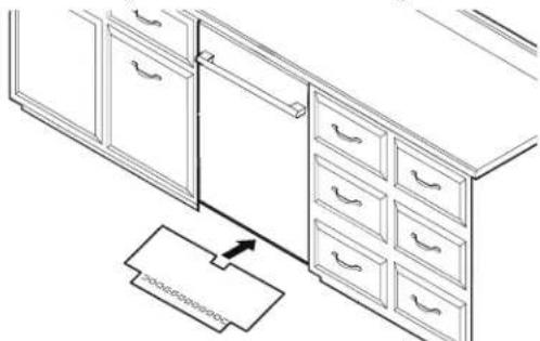
natural_image
Line drawing of a kitchen cabinet with drawers and a hanging drawer (no text or symbols)After pushing the dishwasher in the cabinet opening, the leveling feet to standard height ^7/8 "of(880 mm) and up. Then take the floor insulation pad and slide it front (gap between the floor & the drip tray).
The floor pad is designed to go around the leveling
- Pull slack from utilities
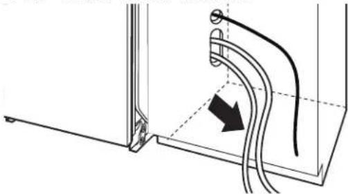
natural_image
Technical line drawing of a mechanical assembly with curved pipes and a directional arrow (no text or symbols)NOTE: Pull slack out of utilities at the same time the dishwasher is pushed into the cabinet opening to avoid any kinks.
Custom Panel Installation (on some models)
Custom Panel Dimension
Make sure that the custom panel is as per the recommended dimensions. See below image for the recommended dimensions.
A. 239/16" (598 mm)
B. 28 ^3 / _8 "-30" (720-762 mm)
C. 5/8"-1" (16-25 mm)
A customer supplied door panel must weigh no more than 16 (7.3 kg) with the handle (together). And must be made to spe dimensions as given above. It is recommended that a cabinet maker cut the custom panel because of the precise dimensions needed.
NOTE: The handle for the custom panel is not included.
Custom Panel Installation steps
legs. In an area that is flat and clear of debris, place down a as a work surface.
- Attach the custom panel handle as you would any other cabinet handle. Be sure to protect the finished surface with painters tape when preparing and recessing the rear panel I conceal attachment hardware.
- Install the custom hardware handle(s) on the front of the custom panel, inside dotted line as shown below
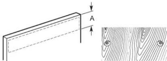
natural_image
Technical diagram showing a wooden plank with dimension A and a corresponding cross-section of wood grain texture (no text or symbols)A. 6" (152.4 mm)
IMPORTANT: If the handle is attached from the back of the custom panel, the screw holes should be countersunk for the screw heads to be flush with the panel. If the handle is attached to the front of the custom panel, the screw length cannot exceed the panel thickness.
- Place the custom panel with the face side down on the9. Attach double sided adhesive to the door panel in the lowe blanket, and note the planned top and bottom of the panelhaff, to temporarily aid in door alignment. These pieces of applicable. adhesive can be removed later after getting all the holes
A. 23 ^5/8 " (600 mm)
B. 22 ^1/16 " (560 mm)
C. 2^9/_16 " (65 mm)
- Using a tape measure, measure the top, center and bottom width of the panel, and mark the center location with either the edge of a tape piece or with a fine point pencil.
- Using the straight edge draw a line connecting all the marked center lines so that the center of the panel is identified.
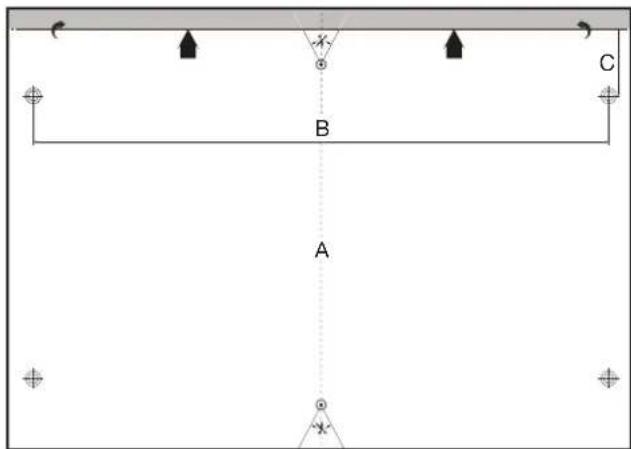
- Using the provided template, align the centerline of the template with the center line of the door.
natural_image
Simple line drawing of a dropper or pipette (no text or symbols)
natural_image
Simple line drawing of a horizontal bar with evenly spaced segments (no text or symbols)Awl Center punch
- Using a center punch or awl, mark the 2 locations on the template to be used for attaching the door studs. Remove the template. Attach the 2 door studs to custom panel using the included screws.
A. 3.5 mm x 18 mm Phillips head screw (2)
B. #2 Phillips screwdriver
C. Studs
natural_image
Simple line drawing of a rolled-up adhesive tape (no text or symbols)Double sided adhesive
- Insert one of the wood blocks from the packaging across door opening to prop the door slightly open.
- Align the two door studs to the referenced tracks on the lifting up the door until the top panel is flush with the top dishwasher door.
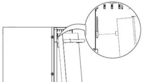
natural_image
Technical line drawing of a mechanical assembly with an inset magnified detail (no text or symbols)- While holding the alignment, press on the lower section of door, to allow the double sided tape to grab and hold you alignment.
natural_image
Technical line drawing of a mechanical assembly with two views (top and side), no text or symbols present.- If this process needs adjusting, Use a plastic putty knife between the panel and the door to relieve the double sided tape and free the panel.
-
Open the door and panel together to the fully open positive making sure the panel has not shifted.
-
Consider the material choice of the custom panel and the 1st of the 4 included door panel screws using a screwdriver. Check to ensure the door panel is still all Repeat the screw installation for ^nd thele2
A. 4 x 38 mm Phillips head screw (4)
B. #2 Phillips screwdriver
C. Custom panel
- Check to ensure the door panel is still aligned.
- Repeat the screw installation for the last 2 screws.
- If desired, remove the screws and the panel to remove temporary double sided tape.
- If the door to cabinet gaps are not even, make an ad to the dishwasher by loosening all 4 screws mounted to adjacent cabinets. Make the position adjustment.
- Retighten all 4 screws mounted to the adjacent cabinets screws need to be tight to prevent the dishwasher from moving.
Electrical Connection
Phillips If house wiring does not reach into the adjacent cabinet to the dishwasher junction box mounting location, the house wiring will first need to be corrected by a qualified electrician in conforma with the National Electrical Code, ANSI/NFPA 70 - latest edition and all local codes and ordinances.
WARNING

Fire Hazard
Use only the junction box supplied with the product when making electrical connections.
Do not bypass the junction box.
Failure to follow these instructions can result in death, fire, or electrical shock.
WARNING

Electrical Shock Hazard
Electrically ground appliance.
Connect wires together inside the junction box using the supplied wire nuts.
Do not use an extension cord.
Failure to follow these instructions can result in death, fire, or electrical shock.
Direct Wire Connection
- Route the junction box cable from the dishwasher through the electrical conduit hole in the cabinet wall. Also route the ho wiring through the same hole as shown below.
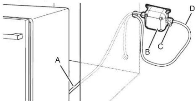
A. Junction box cable
B. Junction box
C. Cable fittings (2)
D. Home wiring
-
Refer to "Junction Box Assembly" section of this Owner's Manual to attach cable fitting to the home wiring and it assembly.
-
After the complete assembly of Junction box with home Secure the junction box to the back of the cabinet wall four screws (not provided). Be sure to avoid driving screw into utility lines possibly located in the wall behind the box.
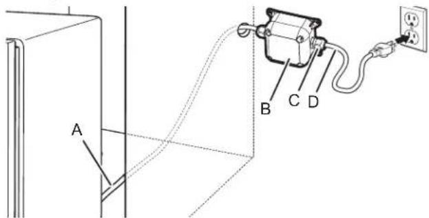
Power Cord Connection
- Use power cord kit (sold separately per Whirlpool Part Number W11670634) and Junction box assembly (included) for connecting the dishwasher to the power supply as shown below. The power cord kit includes a straight plug that is recommended for most installations.
NOTE: To ease some installations, a power cord with a angle plug is also available per Whirlpool Part Number W11645183.

A. Junction box cable
B. Junction box
C. Cable fittings (2)
D. Power cord
IMPORTANT: Do not plug cord into an outlet until instructed to do so.
- Refer to "Junction Box Assembly" section of this Owner's Manual to attach cable fitting to the power cord and its assembly.
- After complete assembly of Junction box with Power cord, Secure the junction box to the back of the cabinet wall using four screws (not provided). Be sure to avoid driving screws into utility lines possibly located in the wall behind the junction box.
Junction Box Assembly
f. The junction box comes in a plastic bag located inside a cardboard box in the lower rack of the dishwasher (previous wiring removed at the beginning of the installation process).
! DANGER

Electrical Shock Hazard
Connect power before servicing.
Fully assemble cable fittings.
Place all wiring inside junction box.
Replace cover before reconnecting power.
Failure to do so can result in death, fire, or electrical shock.
- Route the junction box cable from the dishwasher through the electrical conduit hole in the cabinet wall.
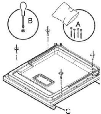
- Use a #2 Phillips screwdriver to remove the Junction box from the junction box (4 screws).
- Remove the plastic bag containing cable fittings and wire nut from the inside of the junction box. Take out the cable fitti and wire nuts from plastic bag.
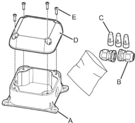
A. Junction box base
B. Cable fittings (2)
C. Wire nuts (3)
D. Junction box lid
E. Screws (4)
- Remove the mounting nuts from cable fittings as shown below.
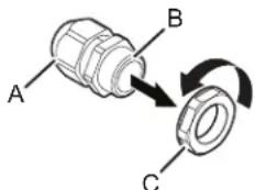
A. Elongated (strain relief) nut
B. Strain relief body
C. Mounting nut
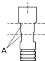
- Attach one cable fitting to the junction box cable from the dishwasher paying thorough attention to the orientation (see below figure). The cable fitting shall tighten against the secondary insulation (PVC jacket).
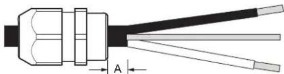
natural_image
Cross-sectional diagram of a cable or connector with labeled section A (no text or symbols beyond label)A. 0.25" (6.35 mm) minimum
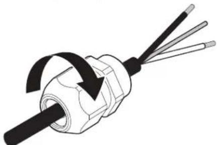
natural_image
Diagram of a screwdriver with three blades and a central shaft, showing internal winding (no text or symbols)Use wrench and/or pliers to fully tighten the elongated (stra relief) nut against the strain relief body.
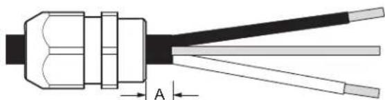
- For Direct (home) wire connection (12-2/14-2 non-metallic sheathed/Romex), Strip jacket insulation of the home wire to expose the wires to the length"of(129.3 mm) as shown below. Strip each wire end by 0.75" (19 mm). Attach the second cable fitting to home wiring paying attention to the orientation (see below figure). Use wrench and/or pliers to fully tighten the elongated (strain relief) nut against the strain relief body.
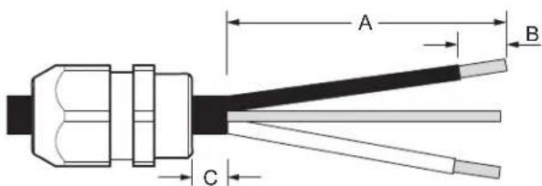
A. 3 ^3/4 " (95 mm)
B. 0.75" (19 mm)
C. 0.25" (6.35 mm) minimum
- For Direct (home) wire connection using armored cable or flexible metal conduit use only a UL/CSA-approved metallic strain relief for the type of conduit being used. Ensure 4" (101.6 mm) of wire is extending out past the end of the strain relief. Strip each wire end by 0.75" (19 mm). Attach the strain relief to the home wiring per the strain relief manufacturer's instructions. Attach strain relief to the box per the strain relief manufacturer's installation instructions.
- For power cord connection, attach the second cable fitting to the power cord paying attention to the orientation (see below figure). Use wrench and/or pliers to fully tighten the elongated (strain relief) nut against the strain relief body.
natural_image
Diagram of a cable connector with labeled section A (no text or symbols beyond label)A. 0.25" (6.35 mm) minimum
NOTE: Non-metallic sheathed wire is for direct wire connection only.
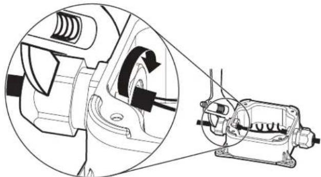
Route wire ends into the junction box through the round h on the sides. Securely attach the cable fittings to the juncti box using plastic mounting nuts supplied with the cable fittings. Hand tighten the mounting nuts to the cable fittings and then use a crescent wrench to tighten another 1/4 turn Use a second wrench or pliers to secure the cable fitting when tightening the mounting nut.
natural_image
Technical line drawing of a mechanical assembly showing internal components and motion direction (no text or symbols)- Connect wires together inside the junction box using the supplied wire nuts. Connect wires of the same color together (black to black, white to white, and bare/green to green). (stram) NOTE: Do not pre-twist wires before making connections.
Wiring configuration
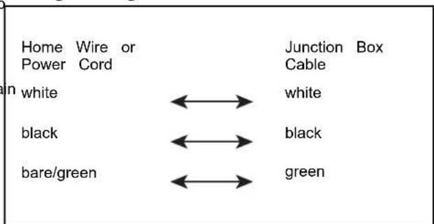
- To apply a wire nut, hold the stripped/bare ends of wires parallel to each other with their ends aligned. Firmly push wires into a wire nut and twist clockwise until secure (the insulated wires outside the connector begin to twist). Gently tug on each wire making sure they are secure.
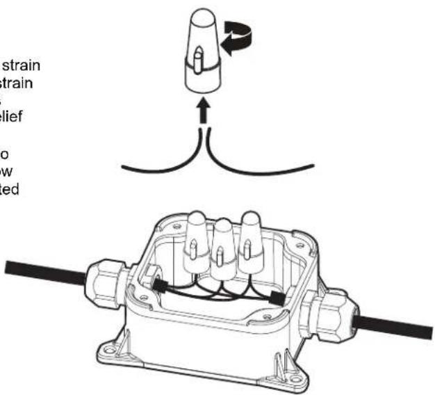
- Re-attach the junction box lid using a #2 Phillips screw23verCheck for plumb and adjust legs if needed
Ensure that wires are not being pinched between the lid and base of the junction box. The Junction box lid must be attached with the 4 screws removed in step 3 and ensure the lid is fully closed and snugly attached to base.

A. Junction box cable
E. Screws (4)
B. Power cord or Home wiring
F. Cable fittings (2)
C. Wire nuts (3)
G. Junction box base
D. Junction box lid
A. 5/16" (8 mm) nut drivers or hexsockets
B. Pliers - Adjustable upto 2" (5.0 cm)
C. Small level
- The junction box is not intended to be used with rigid metal conduit.
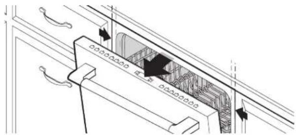
Final Installation Check
- Open and close door
natural_image
Line drawing of a kitchen appliance with a drawer and cabinet, showing a black arrow indicating direction (no text or symbols)- Align Dishwasher Flush to Cabinet
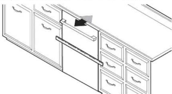
natural_image
Line drawing of a cabinet drawer with drawers and a ruler inserted, no text or symbols presentAlign dishwasher flush to cabinet.
Use an adjustable wrench to adjust the front feet and a 5 (8 mm) socket to adjust the rear foot. Raise the dishwasher to 1/8" (3 mm) of the counter top. Check that the dishwa is centered from left to right in the opening. If needed, ad the leveling legs until the dishwasher is plumb.
Helpful Tip: If the front leveling feet are hard to adjust, protect the customer's floor and use an adjustable wrench. Or alternately, use of 2 or more air shims to temporarily the front of the dishwasher.
Secure Dishwasher in Cabinet Opening
24. Double-check dishwasher alignment in cabinet opening
natural_image
Technical line drawing of a refrigerator interior showing door, drawer, and cabinet layout (no text or symbols)Check that dishwasher is still level front to back and side to side in the cabinet opening.
Open dishwasher door and place towel over pump assembly and spray arm of dishwasher. For some models, you may have to remove lower dish rack. This will keep screws from falling into pump area when you are securing dishwasher to countertop or cabinet.
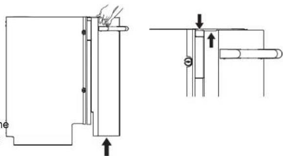
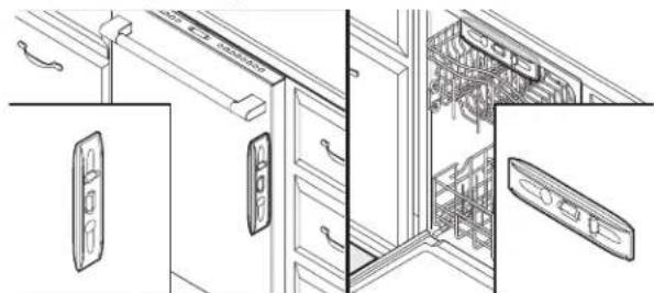
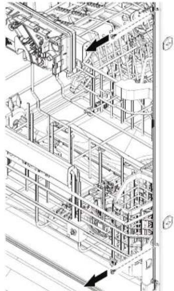
25. Side Gap Covers
- Remove the Side Gap Covers from ^nd level 2rack of the dishwasher.
natural_image
Technical line drawing of an open refrigerator interior showing internal components and structural layout (no text or labels)- Remove the four screw from dishwasher.
natural_image
Technical line drawing of an industrial piping system with no visible text or symbols- Position the Side Gap Cover as shown below and make sure to install the top screw first and the bottom screw last.
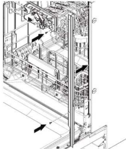
natural_image
Technical line drawing of an industrial automation or mechanical system with internal components and directional arrows (no text or labels)- Repeat above step to install the other Side Gap Cover the dishwasher.
26. For Frame less Cabinets
- Remove upper rack for easier access.
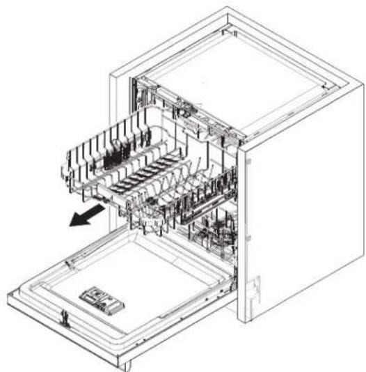
natural_image
Technical line drawing of an open refrigerator internal compartments, showing internal structure and casing (no text or labels)-
Use four Thick plastic (included) spacers between cabinet wall and the side wall panels of the dishwasher.
-
Each spacers has three positions depending on the gap available, insert the spacer into the side panel of the dishwasher and turn the spacer by 90 degrees.
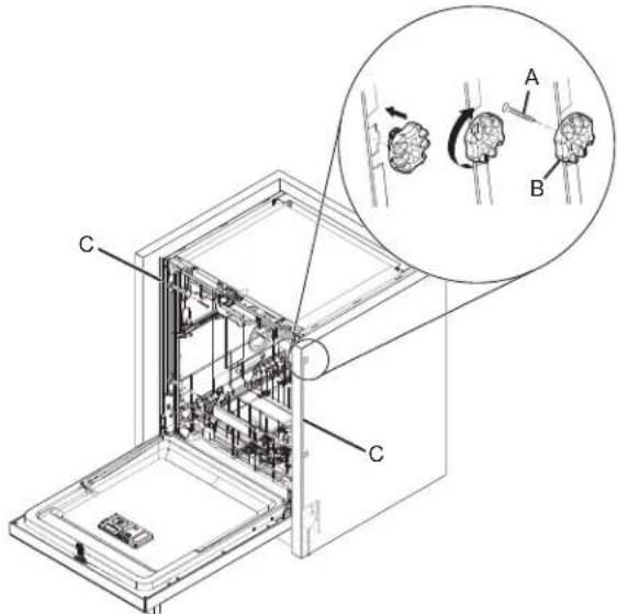
A. 3.5 mm x 18 mm
B. Thick plastic spacers (4)
Phillips-head screws (4)
C. Side gap covers (2)
- Once the spacers are locked into the position. Secure the dishwasher to cabinet with four 3.5 mm x 18 mm Phillips-head screws (included).
NOTE:
■ The dishwasher must be secured to keep it from shifting when the door is opened or closed.
■ Do not drop screws into bottom of dishwasher.
27. For Face Frame Cabinets
- Use four Metal brackets (included) between Face frame and the side wall panels of the dishwasher.
- Each bracket needs to be inserted into the slots at the side panel of the dishwasher and turn the brackets by 90 degrees towards the cabinet opening.
- Once the spacers are locked into position, Secure the dishwasher to cabinet with four 3.5 mm x 18 mm Phillips-head screws (included).
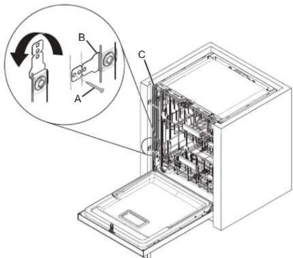
A. 3.5 mm x 18 mm
Phillips-head screws (4)
B. Metal brackets (4)
C. Side gap covers (2)
NOTE:
■ The dishwasher must be secured to keep it from shifting when the door is opened or closed.
■ Do not drop screws into bottom of dishwasher.
28. Break end of the brackets
Depending on the depth of the gap between dishwasher at the face of the frame, Break off the end of the brackets the scored line using pliers to adjust the required length of the bracket. Use sandpaper to smooth any burrs.
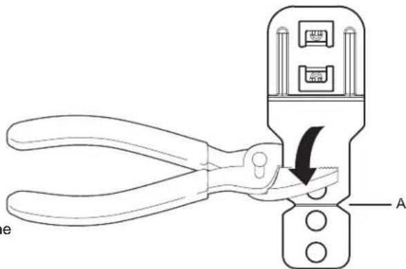
A. Score line
29. Check inner spacing
Open door and check that space between dishwasher cabinet opening and tub is equal on both sides. If spacing is not equal, loosen bracket screws and shift tub. Tighten bracket screws.
Choose Anchor Attachment Method
IMPORTANT: The dishwasher must be secured to the cabinet as one of the final steps. Prepare the dishwasher for this by attaching
the dishwasher to the cabinets using at least 4 of the 6 available screw holes.
30. Cabinet Attachment:
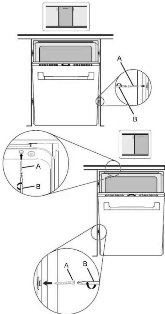
A. #3.5 x 18 mm screws (4) for Cabinet mount
B. #2 Phillips screwdriver
Remove the short screws from the package and insert their into four of the six mounting holes provided. Using a Philli head screw driver, screw them into the cabinet. If longer screws are needed, the installer will need to provide.
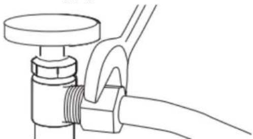
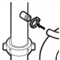
Connect Water Line to House Shutoff Valve
31. Attach water supply line
natural_image
Line drawing of a pipe fitting with a flanged handle and valve (no text or symbols)which the water supply line (flexible braided line) to the h water line using a connection configuration that is in compliance with local codes and ordinances. The water supply to the dishwasher should have a manual shutoff val located under the sink.
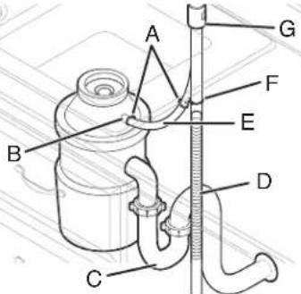
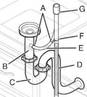
Connect Drain Hose
32. Connect drain hose
Connect drain hose to waste tee or waste disposer using of the following options:
■ Option A: Waste disposer – no air gap
■ Option B: No waste disposer – no air gap
■ Option C: Waste disposer – with air gap
■ Option D: No waste disposer – with air gap
IMPORTANT: The drain hose connection of the disposer or waste tee must be made before the drain trap and at lea 20" (508 mm) above the floor where the dishwasher will be installed.
Helpful Tip: To reduce vibration of the hose, keep the ho away from the floor.
Option A: Waste disposer - no air gap
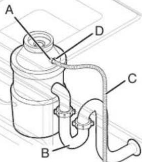
A. Disposer inlet
C. Drain hose
B. Drain trap
D. Drain hose clamp (black color)
Option B: No waste disposer - no air gap
A. Waste tee
C. Drain hose
B. Drain trap
D. Drain hose clamp (black color)
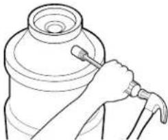
Helpful Tip: Remove disposer knockout plug.
-
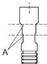
Fit rubber end (A) of drain hose to waste tee and cut if
-
Fit rubber end (A) of drain hose to waste tee and cut if needed. needed.
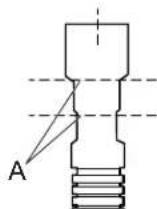
A. Two cut lines
NOTE: Do not cut ribbed section.
- Using a hammer and screwdriver, knock plug into disposer.
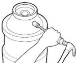
natural_image
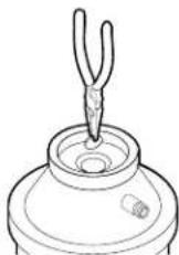
Line drawing of a hand holding a tool next to a cylindrical object (no text or symbols)- Use needle-nose pliers to remove plug.
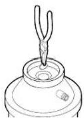
- Attach drain hose to disposer inlet with drain hose clamp (black color) (provided). Use pliers to squeeze clamp open and move into position.

natural_image
Line drawing of a mechanical component with a cylindrical top and threaded end (no text or symbols)
A. Two cut lines
NOTE: Do not cut ribbed section.
- Attach rubber end of drain hose to waste tee with a drain ser. clamp (black color) (provided). Use pliers to squeeze clamp open and move into position. If the drain hose was cut, us 1½" to 2" (38 mm to 50 mm) screw-type clamp (not provi
natural_image
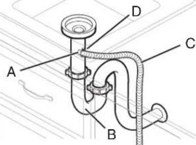
Technical line drawing of a mechanical assembly with a cylindrical component and two connected components (no text or symbols)Option C: Waste disposer - with air gap
A. Screw-type clamps
E. Rubber hose connector
B. Disposer inlet
F. Drain hose clamp (black color)
C. Drain trap
G. Air gap
D. Drain hose
Helpful Tip: Remove disposer knockout plug.
- Using a hammer and screwdriver, knock plug into disposer.
natural_image
Line drawing of a hand holding a tool next to a cylindrical object (no text or symbols)- Use needle-nose pliers to remove plug.
- Connect rubber end (A) of drain hose to air gap and cut if needed.
A. Two cut lines
NOTE: Do not cut ribbed section.
- Attach drain hose to air gap with drain hose clamp (black color) (provided). Use pliers to squeeze clamp open and move into position. If the drain hose was cut/2" use 2" 1 (38 mm to 50 mm)screw-type clamp (not provided).
- Use
natural_image
Diagram of a mechanical assembly with a pipe fitting and a connector (no text or symbols)- Use a rubber hose (not provided) with screw-type clamps (n provided) to connect from air gap to disposer inlet.
natural_image
Simple line drawing of a mechanical component with a coiled spring and connecting rod (no text or symbols)Option D: No waste disposer – with air gap
A. Screw-type clamps
E. Rubber hose connector
B. Waste tee
F. Drain hose clamp (black color)
C. Drain trap
G. Air gap
D. Drain hose
- Connect rubber end (A) of drain hose to air gap and cut needed.
A. Two cut lines
NOTE: Do not cut ribbed section.
- Attach drain hose to air gap with drain hose clamp (black color) (provided). Use pliers to squeeze clamp open and mo into position. If the drain hose was cut, "use 2" 1 (38 mm to 50 mm) screw-type clamp (not provided).
- Use a rubber hose (not provided) with screw-type clamps (n provided) to connect from waste tee to air gap.
natural_image
Technical line drawing of a mechanical assembly with a bolt and nut (no text or symbols)Complete Installation
WARNING

Electrical Shock Hazard
Plug into a grounded 3 prong outlet.
Do not remove ground prong.
Do not use an adapter.
Do not use an extension cord.
Failure to follow these instructions can result in death, fire, or electrical shock.
33. Power supply cord - Plug into a grounded 3 prong outlet
A. Junction box cable
C. Cable fittings (2)
B. Junction box
D. Power cord
Plug into a grounded 3-prong outlet.
34. Reconnect power
Reconnect electrical power at the fuse box or circuit breaker box.
NOTE: With the access panel off, start the dishwasher 37. Install access panels
allow it to complete the shortest wash cycle. After the first
2 minutes, unlatch door, wait 5 seconds, and then open door.
Check that there is water in the bottom of the dishwasher tub.
Check that dishwasher is working properly.
Install Access Panel
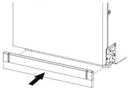
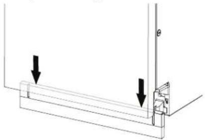
35. Install the toe panel
natural_image
Technical line drawing of a mechanical assembly with an arrow indicating direction (no text or symbols)Install the toe panel as shown in the above image.
36. Check toe panel edge
natural_image
Technical line drawing of a mechanical assembly with two downward arrows indicating force or direction (no text or symbols present)Check that the lower edge of the toe panel touches the f Adjust if necessary.
IMPORTANT: If there is visible gap to the floor after insta the toe panel, replace it with alternate (tall) toe panel supplied with dishwasher, shipped at the back of the dishwasher.
natural_image
Isometric line drawing of a rectangular metal beam with two notches (no text or symbols)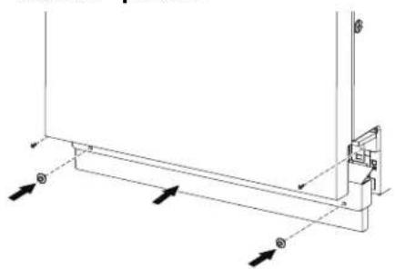
natural_image
Pure technical line drawing of a mechanical bracket or support structure without any text, numbers, or symbolsPlace the access panel against dishwasher legs. Using a Phillips screwdriver or 1/4" nut driver, reinstall the screws through the holes in the access panel.
38. Tighten screws
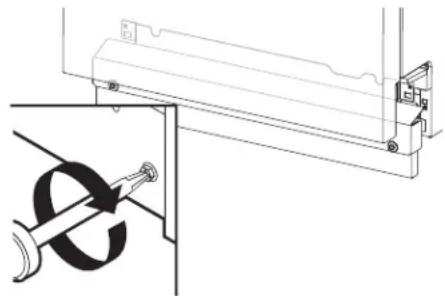
natural_image
Technical line drawing of a mechanical assembly with a bracket and mounting bracket (no text or symbols)Tighten access panel screws.
T-Gasket Installation (on some models)
If an installer will be using a custom access panel to be on top of the unit's access panel and if the installer should cover the seam gap then the T-Gasket bottom could be a between the custom front panel & the access panel.
Custom access panel can be attached to the top of the dishwasher access panel. Installer can use T-Gasket to fill between custom access panel and custom panel door (as below).
A. T-Gasket
B. Polybag
C. 3/16" (5 mm)
D. Custom Access Panel
E. Custom Panel Door
Check Operation
- Read the dishwasher Quick Start Guide that came with your dishwasher.
- Check that all parts have been installed and no steps were skipped.
If the dishwasher is not working properly, disconnect power or unplug dishwasher and refer to the "If Dishwasher Does Not Operate" section.
If Dishwasher Does Not Operate
First try the solutions suggested here to possibly avoid the cos a service call.
■ Has the circuit breaker tripped or the house fuse blown?
■ Is the door closed tightly and latched?
■ Has the cycle been set correctly to start the dishwasher?
■ Is the water turned on?
If none of these possible solutions work, refer to the contact issues to information referenced in your Quick Start Guide.
Additional Tips
Expect longer wash times. Your new dishwasher will average 25 hours per load but use nearly 40% less energy than older models. Designed with a low-wattage, low-energy-consumption motor, your dishwasher washes longer to ensure exceptional cleaning. Certain models are equipped with an optical water sensor, so the first cycle will run longer to calibrate the optica sensor. Selecting certain options could increase cycle time past 3.5 hours.
Rinse aid is necessary for good drying results:
This dishwasher is designed to be used with rinse aid for good drying performance and controlling hard-water-deposit buildup. Energy-efficient dishwashers use less water and energy, so they depend on the water sheeting action of rinse aid for good dry performance.
Start/Resume light may flash:
When pressing Start/Resume, you must make sure the door is closed within 4 seconds. If you do not close the door within 4 seconds, the Start/Resume light will flash until you press it again. (You must also do this when adding a dish during the middle of a cycle.)
- Remove the adhesive strips from the T-Gasket and attach it to the top surface of custom access panel. Start along the left or right edge and continue along that edge.
- Using a paper towel or cloth, press along the front surface of the T-Gasket to ensure it is flushed well.
SÉCURITÉ DU LAVE-VAISSELLE
natural_image
Illustration of a kitchen sink with a faucet and a cylindrical sink, showing a downward arrow indicating a drop (no text or symbols present)natural_image
Line drawing of a person pouring granular material into a bowl on a machine (no text or symbols)natural_image
Two technical diagrams showing hands operating a mechanical device on a platform, with no visible text or symbols.natural_image
Technical line drawing showing mechanical assembly with no visible text or symbolsnatural_image
Two identical line drawings of pliers, no text or symbols present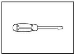
natural_image
Line drawing of a screwdriver with a cylindrical head and threaded shaft (no text or symbols)natural_image
Simple line drawing of a screwdriver (no text or symbols)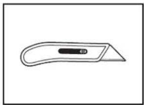
natural_image
Simple line drawing of a flat tool with a handle and central slot (no text or symbols)natural_image
Simple line drawing of a screwdriver with a cylindrical head and threaded shaft (no text or symbols)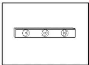
natural_image
Simple line drawing of a rectangular object with three circular symbols on its top (no text or labels)natural_image
Simple line drawing of a tape measure (no text or symbols)
natural_image
Line drawing of a pair of eyeglasses (no text or symbols)natural_image
Line drawing of an adjustable wrench with a screw and handle (no text or symbols)
natural_image
Simple line drawing of a dropper or pipette (no text or symbols)natural_image
Line drawing of a handheld electric tool with a strap and cable (no text or symbols)
natural_image
Two rectangular panels with dot patterns, no text or symbols presentnatural_image
Line drawing of a pair of pliers (no text or symbols)
natural_image
Line drawing of a pair of pliers with metal fasteners (no text or symbols)Pince à dénuder
Pince

natural_image
Line drawing of a handheld electric drill bit (no text or symbols)
natural_image
Simple line drawing of a rolled-up adhesive tape (no text or symbols)natural_image
Line drawing of a mechanical tool kit with no visible text or symbolsAspirateur portable
natural_image
Simple line drawing of a flashlight with a handle and circular button (no text or symbols)Lampe de poche
natural_image
Simple line drawing of a bucket with a handle (no text or symbols)natural_image
Two identical wire handles with handles, shown in side profile (no text or symbols)natural_image
Simple line drawing of a horizontal pipe or lever (no text or symbols)natural_image
Simple line drawing of a folded paper or plastic sheet (no text or symbols)Serviette de bain
natural_image
Line drawing of a folded or curled sheet with no text or symbolsnatural_image
Illustration of a screw with two circular fasteners (no text or symbols)natural_image
Technical line drawing of a mechanical component with mounting flanges and a central housing (no text or symbols)natural_image
Simple line drawing of a rolled-up sheet of paper or material (no text or symbols)natural_image
Line drawing of a 3D cube-shaped device with a circular vent and two labeled buttons (no text or symbols)ser
natural_image
Technical line drawing of a mechanical connector (no text or symbols)natural_image
Three identical conical objects with central holes, shown in line drawing style (no text or symbols)natural_image
Technical line drawing of a protractor and ruler (no text or symbols)Équerre combinée
natural_image
Technical line drawing of a mechanical component with gear-like features (no text or symbols)natural_image
Technical line drawing of a mechanical bracket or connector (no text or symbols)natural_image
Pure technical line drawing of a diagonal bracket (no text or symbols)natural_image
Line drawing of a screw with a threaded head and circular head (no text or symbols)natural_image
Line drawing of a mechanical connector or tool with threaded ends and flanges (no text or symbols)natural_image
Simple line drawing of a two-bar electrical component (no text or symbols)natural_image
Illustration of a coiled, ribbed wire or filament (no text or symbols)natural_image
Simple geometric shape: a diagonal line inside a rectangle (no text or symbols)natural_image
Simple line drawing of a screw with no text or symbolsnatural_image
Simple line drawing of a speaker cone (no text or symbols)pōtonlaoir à sel

natural_image
Pure 3D geometric shape diagram with no text, numbers, or symbolsnatural_image
Simple line drawing of two cylindrical mechanical parts (no text or symbols)natural_image
Simple line drawing of a diagonal line with no text or symbolsnatural_image
Illustration of a coiled hose with mesh pattern and connectors (no text or symbols)natural_image
Two interlocked circular pipe clips with metal fasteners (no text or symbols)Bride à vis
natural_image
Line drawing of a USB connector (no text or symbols)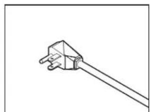
natural_image
Simple line drawing of a plug with a cable, no text or symbols presentnatural_image
Line drawing of a kitchen sink with faucet and three washers (no text or symbols)A. Brise-siphon
National Fire Protection Association
1 Batterymarch Park
Quincy, MA 02169-7471
natural_image
Pure technical line drawing of a structural frame with no text, numbers, or symbolsnatural_image
Technical line drawing of a mechanical bracket assembly with directional arrows (no text or symbols)natural_image
Technical line drawing of a mechanical assembly with a rotating component and mounting bracket (no text or symbols)natural_image
Technical line drawing of a mechanical bracket assembly with an arrow indicating direction (no text or symbols)natural_image
Line drawing of a standard office desk with nine drawers and six drawers (no text or symbols)natural_image
Line drawing of a mechanical tool or connector with threaded ends and a flanged shaft (no text or symbols)natural_image
Illustration of a coiled cable with mesh texture and connectors (no text or symbols)natural_image
Illustration of a coiled hose with a connector and hook, no text or symbols presentnatural_image
Line drawing of a kitchen sink with faucet and water drop (no text or symbols)natural_image
Line drawing of a kitchen cabinet with drawers and a hanging drawer (no text or symbols)natural_image
Technical line drawing of a mechanical assembly with curved pipes and a directional arrow (no text or symbols)natural_image
Technical diagram showing a wooden plank with cross-section view and corresponding wood grain texture (no text or symbols)A. 6 po (152,4 mm)
A. 23 5/8po (600 mm)
B. 22 1/16 po (560 mm)
C. 2%/16 po (65 mm)
natural_image
Simple line drawing of a dropper or pipette (no text or symbols)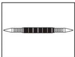
natural_image
Simple line drawing of a horizontal bar with evenly spaced segments (no text or symbols)Poinçon Pointeau

natural_image
Simple line drawing of a rolled-up adhesive tape (no text or symbols)Adhésif double face
natural_image
Technical line drawing of a mechanical assembly with an inset magnified detail (no text or symbols)natural_image
Technical line drawing showing mechanical assembly with no text or symbolsnatural_image
Cross-sectional diagram of a cable or connector with labeled section A (no text or symbols beyond label)A. 0,25 po (6,35 mm) minimum
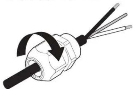
natural_image
Diagram of a mechanical component with three wires and a rotating arrow indicating rotation (no text or symbols)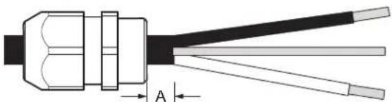
natural_image
Cross-sectional diagram of a cable or connector with labeled section A (no text or symbols beyond label)A. 0,25 po (6,35 mm) minimum
natural_image
Line drawing of a kitchen appliance with a drawer and drawer, showing a black arrow indicating direction (no text or symbols)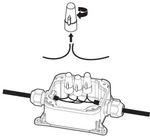
natural_image
Technical diagram showing a connector assembly with wiring and a close-up of the internal components (no text or symbols)natural_image
Line drawing of a cabinet drawer with drawers and a handle, no text or symbols presentnatural_image
Line drawing of a kitchen cabinet interior showing door, drawer, and rack (no text or symbols)natural_image
Technical line drawing of an open refrigerator interior showing internal compartments and structural details (no text or labels)natural_image
Technical line drawing of an industrial facility interior with machinery and structural framework (no visible text or labels)natural_image
Technical line drawing of an industrial machine assembly (no visible text or labels)natural_image
Technical line drawing of an open refrigerator internal compartments, showing internal structure and housing (no text or labels)natural_image
Line drawing of a pipe fitting with a valve and handle (no text or symbols)natural_image
Line drawing of a hand holding a tool next to a cylindrical container (no text or symbols)natural_image
Line drawing of a mechanical component with a cylindrical top and threaded end (no text or symbols)natural_image
Technical line drawing of a mechanical component with a cylindrical top and threaded end (no text or symbols)A. Bride à vis
natural_image
Line drawing of a hand holding a tool next to a cylindrical container (no text or symbols)natural_image
Diagram of a medical or laboratory procedure showing a coiled tube connected to a rod with a separate connector (no text or symbols present)natural_image
Simple line drawing of a mechanical component with a curved pipe and attached ring (no text or symbols)A. Bride à vis
natural_image
Technical line drawing of a mechanical assembly with a bolt and nut (no text or symbols)Achever l'installation
AVERTISSEMENT

natural_image
Technical line drawing of a mechanical bracket with an arrow indicating direction (no text or symbols)natural_image
Pure technical diagram showing a mechanical assembly with two downward arrows indicating force or direction (no text or symbols)natural_image
Simple line drawing of a two-bar electrical component (no text or symbols)natural_image
Technical line drawing of a mechanical bracket assembly with directional arrows (no text or symbols)natural_image
Technical line drawing of a mechanical assembly with a cylindrical component inserted into a bracket (no text or symbols)

- STAINLESS STEEL TUB DISHWASHER OWNER'S MANUAL
- GUIDE D'UTILISATION DU LAVE-VAISSELLE AVEC CUVE EN ACIER INOXYDABLE
- Table of Contents/Table des matières
- Your safety and the safety of others are very important.
- DANGER
- WARNING
- IMPORTANT SAFETY INSTRUCTIONS
- SAVE THESE INSTRUCTIONS
- GROUNDING INSTRUCTIONS
- For a grounded, cord-connected appliance:
- For a permanently connected appliance:
- DISHWASHER MAINTENANCE AND CARE
- User-Maintenance Instructions
- Cleaning the Exterior
- Cleaning and Maintaining the Interior
- To Reduce Risk of Property Damage During Vacation or Extended Time Without Use
- Setting Menu
- Water Softening System
- Water Hardness Setting
- Filling The Salt Reservoir
- Cleaning the Filters
- Very Hard Water
- Filter Removal Instructions
- Cleaning Instructions
- INSTALLATION REQUIREMENTS
- Tools and Parts
- Phillips screwdriver Utility knife
- Cabinet Grommet (corrugated Moisture Barrier Tape
- x 18 mm screws (4)
- Optional Accessory Parts Available:
- First-Time Installations
- Additional Parts Needed (not provided):
- Screw-Type Clamps
- For Power Cord
- Power Cord Kit
- Location Requirements
- Cabinet Opening Dimensions
- Clearances
- Drain Requirements
- Water Supply Requirements
- Electrical Requirements
- You Must Have:
- We Recommend:
- Circuit Requirement:
- If Connecting Dishwasher with a Power Cord:
- If Connecting Dishwasher with Direct Wiring:
- INSTALLATION INSTRUCTIONS
- You Need To:
- Before You Begin
- Electrical Shock Hazard
- Disconnect power
- Shut off water supply
- Prepare Cabinet Opening – New Utilities
- Drill hole location for Water Supply and Drain hose (Preferred hole type)
- Drill location for Electrical conduit hole
- Sand holes smooth
- Install Moisture Barrier (Recommended for Wood Countertops)
- Built-up floors - add shims as needed
- Prepare Dishwasher
- Remove Access and Toe Panels
- Access panel
- Connect Water Line to Fill Valve
- Height a Drain Hose Extension is Required
- Install Door Handle (on some models)
- Install Door Handle
- Place Dishwasher in Cabinet
- Move dishwasher close to cabinet opening
- Adjust side spacers
- Custom Panel Installation (on some models)
- Custom Panel Installation steps
- Electrical Connection
- Direct Wire Connection
- Power Cord Connection
- Junction Box Assembly
- Final Installation Check
- Secure Dishwasher in Cabinet Opening
- Double-check dishwasher alignment in cabinet opening
- Side Gap Covers
- For Frame less Cabinets
- NOTE:
- For Face Frame Cabinets
- Break end of the brackets
- Check inner spacing
- Choose Anchor Attachment Method
- Cabinet Attachment:
- Connect Water Line to House Shutoff Valve
- Attach water supply line
- Connect Drain Hose
- Connect drain hose
- Complete Installation
- Power supply cord - Plug into a grounded 3 prong outlet
- Reconnect power
- Install Access Panel
- Install the toe panel
- Check toe panel edge
- Tighten screws
- T-Gasket Installation (on some models)
- Check Operation
- If Dishwasher Does Not Operate
- Additional Tips
- SÉCURITÉ DU LAVE-VAISSELLE
- Bride à vis
- Achever l'installation
- AVERTISSEMENT
Brand : KITCHENAID
Model : KDTF324PPA
Category : Washing machine