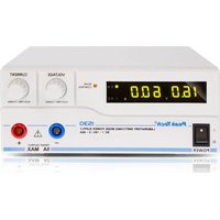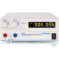
1560 - Measuring equipment PeakTech - Free user manual and instructions
Find the device manual for free 1560 PeakTech in PDF.


User questions about 1560 PeakTech
0 question about this device. Answer the ones you know or ask your own.
Ask a new question about this device
Download the instructions for your Measuring equipment in PDF format for free! Find your manual 1560 - PeakTech and take your electronic device back in hand. On this page are published all the documents necessary for the use of your device. 1560 by PeakTech.
USER MANUAL 1560 PeakTech
Switching mode DC power supply/
1.1 Introduction....26
-
Features....26
-
Controls and Indications (P 1525 and P 1535)....26
-
Controls and Indications (P 1530 and P 1560)....27
-
Installation....28
5.1 Safety Precautions ...... 29
5.2 Connection and operation 29
- Additional functions....29
6.1 Remote sensing (P 1530) ....30
6.2 Control mode selection 30
6.3 Normal mode....30
6.4 Preset mode 30
6.5 Set mode 31
6.6 Define presettings (P1/P2/P3)....31
6.7 Restore factory setting 32
6.8 Manual zeroing of the current display 33
6.9 Remote control mode....33
7. Operation....34
8. Adjustments with control knobs....35
9. Remote control .... 35
9.1 Remote control (P 1525/ 1535)....35
9.2 Remote output ON/OFF (P 1525/ 1535)....36
9.3 Remote control (P 1530/ 1560)....37
9.4 Remote control of voltage control 39
9.5 Remote control (P 1530/ 1560)....41
10. Specifications 42
11. Trouble shooting 43
11.1 OVP: Over voltage protection 43
11.2 OTP: Over temperature protection....43
11.3 OLP: Overload protection....44
5. Installation....50
text_image
7 8 MAIN OUTPUT - Remote Control P1 P2 P3 RECALL MODE Normal Preset Remote Ctrl Set 10 11 12 SANDOUT EXTRAAMOUNTtext_image
rPr Yes C.N. A C.C VOLTAGE PLOW RATE/CCS CURRENT PLOW RATE/CCStext_image
Diagram showing a connector pin layout with numbered pins and a red dotted circle highlighting the connector's position.flowchart
graph LR
    A["Initial Component"] --> B["Assembly Step"]
    B --> C["Red-Circled Section"]
    C --> D["Final Assembly"]
text_image
Diagram showing a connector pinout with numbered pins and a red dotted arrow pointing to a circular component layout.flowchart
graph LR
    A["Initial Component"] --> B["Step 1: Rotation of Outer Ring"]
    B --> C["Step 2: Rotation of Internal Motor"]
    C --> D["Final Assembly"]
text_image
Diagram showing a connector pinout with numbered pins and a red arrow pointing to a circular component layout.This product complies with the requirements of the following directives of the European Union for CE conformity: 2014/30/EU (electromagnetic compatibility), 2014/35/EU (low voltage), 2011/65/EU (RoHS).
We herewith confirm that this product meets the essential protection standards, which are given in directions of council for adaptation of the administration regulations for UK of Electromagnetic Compatibility Regulations 2016 and the Electrical Equipment (safety) regulations 2016.
UK CA CE
To ensure safe operation of the equipment and eliminate the danger of serious injury due to short-circuits (arcing), the following safety precautions must be observed.
Damages resulting from failure to observe these safety precautions are exempt from any legal claims whatever.
* Read these operating instructions carefully and make them available to subsequent users as well.
* It is essential to observe the warning notices on the device, do not cover or remove them.
* Familiarize yourself with the functions of the device and its accessories before using it for the first time.
* Do not operate the device unsupervised or only protected against unauthorized access.
* Use the device only for the purpose of its intended use and pay particular attention to the warning notices on the device and information on the maximum input and output values.
* Before connecting the device to a socket, check that the voltage setting on the device corresponds to the existing mains voltage
* Only connect the device to sockets with an earthed neutral conductor.
* Do not place the device on a damp or wet surface.
* It is essential to keep the ventilation slots in the housing free (if the cover is covered, there is a risk of heat build-up inside the device).
* Do not insert any metal objects through the ventilation slots.
* Do not place any liquids on the device (risk of short circuit if it tips over).
* Never use the device if it is not completely closed.
* Replace defective fuses only with a fuse that corresponds to the original value.
* Never short-circuit the fuse or fuse holder.
* Check the device and accessories for possible damage or bare or kinked cables and wires before commissioning. If in doubt, do not take any measurements.
* It is essential to observe the warning notices on the device.
* Do not expose the device to extreme temperatures, direct sunlight, extreme humidity or moisture.
* Avoid strong vibrations.
* Do not operate the device near strong magnetic fields (motors, transformers, etc.).
* Clean the housing regularly with a damp cloth and a mild cleaning agent. Do not use any corrosive abrasives.
* This device is only suitable for indoor use only.
* Avoid any proximity to explosive and flammable substances.
* Opening the device and maintenance and repair work may only be carried out by qualified service technicians.
* Never short-circuit the remote sensor connections
* Do not make any technical changes to the device.
Cleaning the cabinet
Prior to cleaning the cabinet, withdraw the mains plug from the power outlet. Clean only with a damp, soft cloth and a commercially available mild household cleanser. Ensure that no water gets inside the equipment to prevent possible shorts and damage to the equipment.
1.1 Introduction
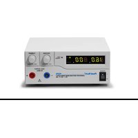
The models PeakTech ^® 1525 / 1530 / 1535 / 1560 Switching Mode DC Power Supplies provide high power output with it small size and lightweight. They are suitable for a variety of uses, especially for DC operated radio equipment.
Please read through this operation instruction carefully and follow the instructions to prevent from abuse or misuse. This manual must be kept for reference at anytime in need.
NOTE:
Laboratory Power Supplies are not designed for charging batteries. Any use of this type can cause serious damage to the device, which are exempt from any legal claims whatever.
Operation with inductive loads
Please note that our power supplies are designed for resistive or capacitive loads.
When using an inductive load, e.g. electric motors, it may damage the power supply.
The power supply has protective functions against short circuit and overload, but it is not protected against inductive reverse voltages, which can be caused by electric motors or batteries.
2. Features
- Lightweight and Small Size: Switching mode power supply has the advantages of lightweight and small size. Comparing with linear mode power with the same power output, it is much lighter and smaller.
- High Efficiency: The unit is operated with efficiency over 85% (P 1525/1535); 87% (P 1530); 86% (P 1560); under the best condition.
- Overload Protection: The constant current limiting protection is adopted to prevent from overload. The overload indicator will be lighted up when the unit is overloaded.
- Over Temperature Protection: The over temperature circuitry is functioned when the unit is over a certain high temperature to prevent the unit from damage by the high temperature. When the circuitry is functioned, the output voltage and current will drop down to a safety value.
- Over Voltage Protection: The over voltage circuitry the unit and the loading equipment form damage by abnormal high output voltage.
- High RFI Stability: The high protection circuitry against RFI (Radio Frequency Interference) provides a stable operation.
- Variable Voltage Output: The variable range of output voltages enables good fits with various uses.
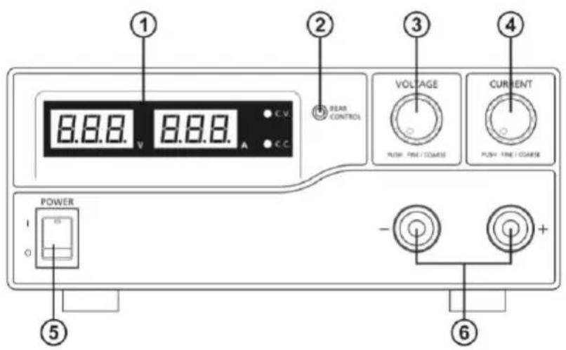
3. Controls and Indications (P 1525 and P 1535)
text_image
1 2 3 4 VOLTAGE CURRENT POWER - + - + 5 6 8.8.8 V 8.8.8 A C.V. C.C. EWR CONTROL PUSH FIRE / COARSE PUSH FIRE / COARSE
text_image
7 8 9 10 MAIN OUTPUT + - MODE Normal Preset Remote Coil Set SENSE Remote Control 11 12 13- LED panel meter display with CC/CV Indictor
- Rear Control Indicator (lights up when using Preset/ Remote Control/ Set mode)
- Output Voltage Control Knob (control both the main and auxiliary output voltage)
- Output Current Control Knob (control both the main and auxiliary output current limit)
- Power ON/OFF Switch
- Aux. Output terminal (max 5A)
Note: The total rated current is 40 A (P 1525) resp. 20 A (P 1535) (Aux.+Main)
- Output Terminal
- Mode Selection Switch (Normal, Preset, Remote Control, Set Modes)
- Recall Selection Switch
- Remote Control Terminal
- Cooling Fan Air Intake Grille
- AC Input Plug
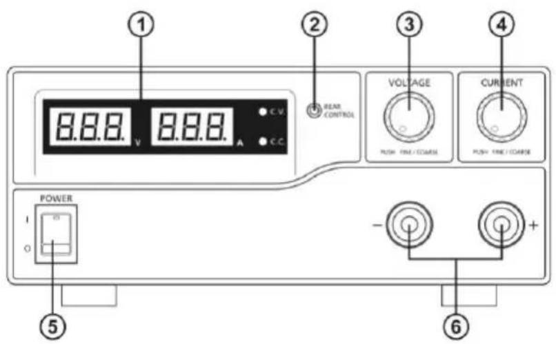
4. Controls and Indications (P 1530 and P 1560)
text_image
1 2 3 4 8.8.8 V 8.8.8 A C.V. BEAR CONTROL VOLTAGE PUSH FIRE / COARSE CURRENT PUSH FIRE / COARSE POWER - + 6 5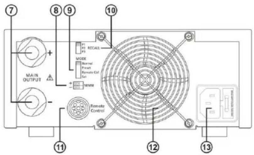
text_image
7 8 9 10 MAIN OUTPUT + - 11 P1 P2 RECALL P3 MODE Normal Reset Remote Ctrl Set + - SENSOR Remote Control 12 13- LED panel meter display with CC/CV Indictor
- Rear Control Indicator (lights up when using Preset/ Remote Control/ Set mode)
- Output Voltage Control Knob (control both the main and auxiliary output voltage)
- Output Current Control Knob (control both the main and auxiliary output current limit)
- Power ON/OFF Switch
- Aux. Output terminal (max 5A)
Note: The total rated current is 60 A (P 1530) resp. 30 A (P 1560) (Aux.+Main)
- Output Terminal
- Remote Sensing Terminal (P 1530 only)
- Mode Selection Switch (Normal, Preset, Remote Control, Set Modes)
- Recall Selection Switch
- Remote Control Terminal
- Cooling Fan Air Intake Grille
- AC Input Plug
5. Installation
- Make grounding the unit to prevent from electric shock at high voltage caused by leakage or lightning.
- Do not place the unit in high humid, dusty and/or sunshiny places.
- Place the unit in a location where allows free air circulation.
- Couple with an AC outlet directly, as source via distribution cables may heat plugs and cable.
- Put the unit horizontally for accurate meter readings.
For Indoor Use Only.
- Do not use the unit for the equipment requiring higher current input respectively starting current than the designed value otherwise damages the unit.
- Do not replace the fuse before ceasing problems and the assigned value of fuse must be used in place. (P 1525/1535 = T4L250V; P 1530/1560 = T8AL250V)
- If the external flexible cable or cord of this power supply is damaged, it shall be replaced by a special cord or assembly available from the manufacturer or his service agent.
5.1 Safety Precautions
- Never touch the unit when your hands are wet.
- Never operate the unit if foreign materials such as metallic objects, water, or other debris have fallen inside. Contact your dealer for check and repair.
- Never allow foreign objects to touch the DC Power Output Terminals.
- Laboratory Power Supplies are not designed for charging batteries. Any use of this type can cause serious damage to the device, which are exempt from any legal claims whatever.
5.2 Connection and operation
- Make sure the AC power source fits the input of voltage unit labelled and plug it in the AC outlet.
- Turn ON the unit and adjust the output voltage to match with the input voltage of the equipment. The turn OFF the unit.
- Connect the equipment to the unit. Red (+) is connected to the positive polarity input of the equipment and Black (-) is connected to the negative polarity input of the equipment.
- First turn ON the unit and then turn the equipment ON.
- When and operation is finished, turn off the equipment first and then turn OFF the unit.
6. Additional functions
The following steps explain how to use the special features: remote sensing and remote control. You can use the features at the same time or separately. F position (rear panel).
6.1 Remote sensing (P 1530)
• Take note of the warnings, wrong disconnection sequence will damage the Power Supply
- Warning: Never short the Remote Sensing Terminal
• Always disconnect Remote Sensing Terminal first.
Connection:
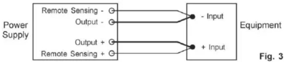
- First complete the power connections between power supply and equipment.
- Check and make sure the power connections are secure.
- Then make connections between Remote Sensing and equipment.
Warning!: Never short the Remote Sensing Terminal
Never connect the Remote Sensing Terminal in reverse polarity
Fig.3 showing connections between Remote Sensing, Power output and Equipment.
flowchart
graph LR
    A["Power Supply"] --> B["Remote Sensing -"]
    A --> C["Output -"]
    A --> D["Output +"]
    A --> E["Remote Sensing +"]
    B --> F["- Input"]
    C --> G["+ Input"]
    D --> H["Equipment"]
    E --> I["Equipment"]
The remote sensing wire should be AT LEAST 22AWG (0,33mm2)wire size.
Disconnection: Wrong disconnect sequence will damage power supply
- First disconnect the remote sensing connections.
- Then disconnect the power connections between the power supply and equipment.
6.2 Control mode selection
There are 4 modes, Normal, Preset, Set and Remote Control mode for the power supply.
Slide the Mode Selection Switch (8) P 1525/1535 or (9) P 1530/1560 to your desired Mode.
The power supply is factory preset to Normal Mode with maximum current level CC.
6.3 Normal mode
This is the factory preset mode and the power supply output V, I are controlled by the dual action volume knobs.
Push the knobs to toggle the coarse and fine tuning, notice the subtle changes in brightness of related LED.
Adjust the knobs to your desired values by trying coarse and fine tuning.
To check the preset current level, just turn the Current Knob lightly in any direction.
The display will resume its normal brightness after few seconds to double confirm your adjustment.
6.4 Preset mode
- In this mode, the Rear Control Light is on to indicate panel V & I controls are de-activated.
- There are 3 preset output P1/ P2/ P3 at the Recall Selection Switch (8) or (9) P 1535.
- The preset values are factory set as following table.
- End user can set his own output rating, please refer to paragraph 6.5.
| Recall No. | Output Voltage | Output Current |
| P 1 | 5V | maximum |
| P 2 | 13,8V | maximum |
| P 3 | PeakTech 1525: 16VPeakTech 1530: 16VPeakTech 1535: 32VPeakTech 1560: 25V | maximum |
6.5 Set mode
First enter into the Set Mode by pushing Switch (8) to Set Mode slot. The power supply is then ready to be preset.
6.6 Define presettings (P1/P2/P3)
- Select the Recall Switch (9) to the position P1, P2 or P3 which you want to set
- Adjust the front panel voltage control knob to set your desired voltage value
- Adjust the front panel current control knob to set your desired current limit value
- Repeat the procedure for remaining recalls P1, P2, P3 if desired.
- Move Mode Switch (8) from "Set" to "Preset" position to confirm your settings.
Remarks:
All the set values in the presets will be kept even after the power supply has been turned off. Always check output voltage of Presets before connect to Load. To check the preset values, move Mode Switch (8) to Preset position. Move the Recall Switch (9) to P1, P2 or P3. The V and I settings of corresponding RECALL P1, P2, P3 will be show on the panel meters.
6.7 Restore factory setting
In session 6.5.1. you learning how to set 3 preset output to you preferred value. In case you need to reset it to factory default, you can do it in MENU mode.
Press and hold Voltage Control Knob for 30s to enter MENU mode.
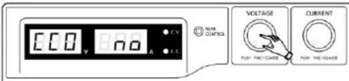
text_image
100 V C.V A C.C NEAR CONTROL VOLTAGE PUSH TIME/CHARGE CURRENT PUSH TIME/CHARGEWhen it is showing"CCO", rotate Voltage Control Knob until Voltage meter showing"rPr".
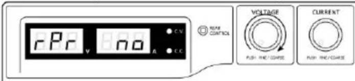
text_image
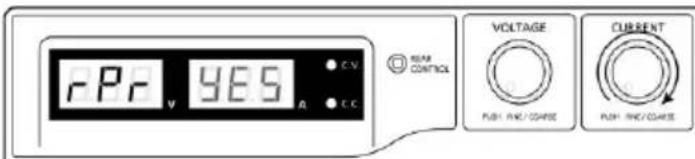
C.V. R/PV V VOLTAGE PUSH RNC/CORSE CURRENT PUSH RNC/CORSEThe Current meter is showing "no" at this time. Then rotate Current Control Knob until Current meter showing "YES".
text_image
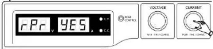
RPR YES C.V C.C REAR CONTROL VOLTAGE PUSH RING/CHARGE CURRENT PUSH RING/CHARGEThe Current meter is showing "no" at this time. Then rotate Current Control Knob until Current meter showing "YES". Press Current Control Knob once to confirm. The "YES" will be lighted afterpreset output being reset to factory default value.
text_image
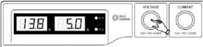
rPr YES C.V. C.C NEAR CONTROL VOLTAGE PON: TIME/CONTANCE CURRENT PON: TIME/CONTANCEFinally press Voltage Control Knob to exit MENU mode
text_image
13.8 V 8.5.0 A C.V EAS CONTROL VOLTAGE PUSH PREI/CONSEE CURRENT PUSH PREI/CONSEE6.8 Manual zeroing of the current display
The power supply will auto-zeroing the current meter offset when powered up. In case it is needed to reset current meter to zero during test and you do not want to restart power supply. You can manually reset it to zero in menu mode.
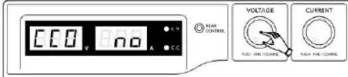
Press and hold Voltage Control Knob for 30s to enter MENU mode. It shows
text_image
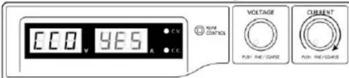
ECO No A C.V REAR CONTROL VOLTAGE CURRENT PUSH KNEI/DOANE PUSH KNEI/DOANERotate Current Control Knob until the Current meter showing
text_image
CDD YES A C C NEAR CONTROL VOLTAGE PUSH RINE/CORRISE CURRENT PUSH RINE/CORRISEThen press Current Control Knob once to confirm. The "YES" will be lighted after successful zeroing current meter offset.

text_image
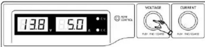
ECO YES VOLTAGE CURRENT PULL RING/CHARGE PULL RING/CHARGEFinally, press Voltage Control Knob to exit MENU mode.
text_image
13.8 V 5.0 A C REAR CONTROL VOLTAGE PULL RING/CHARGE CURRENT PULL RING/CHARGE6.9 Remote control mode
To control the output voltage and current by remote control connector (10)
7. Operation
- This series has 4 models. Make sure you have used the correct one. They have different output voltage range and current as following:
| Model Number | Output Voltage Range | Total Rated Current |
| PeakTech^® 1525 | 1 – 16 V | 0-40 A |
| PeakTech^® 1530 | 0-60 A | |
| PeakTech^® 1535 | 1 – 32 V | 0-20 A |
| PeakTech^® 1560 | 0-30 A |
-
Make sure the Mode Switch (8) is at Normal Position. (9) P 1530
-
The power supply will perform a series of self checks when it is switched on. The LED and other indicators on the front panel will be on by turn. When the cooling fan is being checked, a high speed wind noise can be heard.
-
After the self checks, the CV, V and A LED indicators are lit up displaying voltage and 0.0 current. To find out about the set CC current level, just turn the current control knob one click in either direction. The current display returns to 0.0 after a few seconds.
Below table to show the self test sequence
| Self test display and Sequence | Test contents |
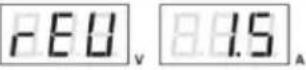 | To show software version |
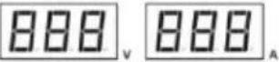 | Segment check |
 | C.V. Indicator check |
 | C.C. Indicator check |
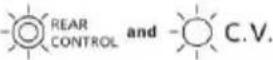 | Rear control indicator check |
 | Return to C.V. |
 | Start to check |
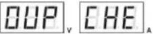 | Over voltage protection check |
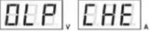 | Over load protection check |
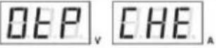 | Over temperature protection check |
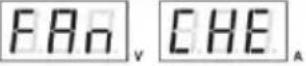 | Fan check |
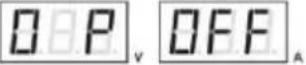 | Output off (remote control mode)(Remote Control Modus) |
8. Adjustments with control knobs
- The rotary encoder control knobs have fine and coarse tuning with clicking movement. Push the knobs to toggle between coarse and fine tuning, notice the subtle changes in brightness of related LED.
- Adjust the knobs to your desired values by trying coarse and fine tuning. The display will resume its normal brightness after few seconds to confirm your adjustment.
- Connect the equipment to the power supply. Red (+) is connected to the positive polarity input of the equipment and Black (-) is connected to the negative polarity input of the equipment.
- Switch on the power supply first and the panel meter & green CV Indicator should light up again.
- Switch on the equipment and the panel meter & green CV Indicator should still remain in green.
- You can now operate the equipment. When an operation is finished, switch off the equipment first and then switch off the power supply.
9. Remote control
9.1 Remote control (P 1525/ 1535)
There are two methods for remote control of current and voltage adjustment.
Both methods require current remote control part to be set up in order for remote control mode to be functional, otherwise unit will be in CC mode all the time.
Method A:
Using two external variable DC voltage sources.
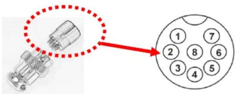
| Remote Socket Pin Assignment for external variable voltage source | ||
| PIN | Functions | Remarks |
| 1 | Internal DC +5V | Less then 50 mA |
| 2 | Voltage Adjustment | 0 – 5 V |
| 3 | Current Adjustment | 0 – 5 V |
| 4 | Ground | |
| 5 | Output OFF | Short to Ground |
| 6 | N.A. | |
| 7 | N.A. | |
| 8 | N.A. | |
Check the output voltage range of the power supply by varying the external voltage source.
Short circuit the main output with 10AWG (5,3mm2) wire to check the display for CC setting varying the external voltage source.
Method B:
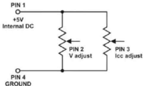
Using two 0-5K Ohm variable resistors
text_image
PIN 1 +5V Internal DC PIN 2 V adjust PIN 3 Icc adjust PIN 4 GROUNDRemark: variable resistors 5KOhm
| Remote Socket Pin Assignment for variable resistor | ||
| PIN | Functions | Remarks |
| 1 | Internal DC +5V | Resistor end |
| 2 | Voltage Adjust | Variable part of resistor |
| 3 | Current Adjust | Variable part of resistor |
| 4 | Ground | Another resistor end |
| 5 | Output OFF | Short to Ground |
| 6 | N.A. | |
| 7 | N.A. | |
| 8 | N.A. | |
Check the output voltage range of the power supply by adjusting the 5Kohm variable resistor.
Short circuit the main output with 10AWG (5,3mm2) wire to check the display for CC setting by adjusting the variable resistor.
9.2 Remote output ON/OFF (P 1525/ 1535)
This remote output on/off control can be activated in any of the modes Normal, Preset, Remote and Set mode.
- By default, Pin 5 is open and output is on.
- Shorting Pin 5 to Pin 4 (ground) and output is off.
- When output is off, the C.V. & C. C. LED's will flash. The current output voltage and current setting will show on the panel meter.
- You can also adjust the output by voltage & current control knob to your desired value, when output is off.
Remark: using the 8pin remote plug provided and connect with 22AWG (0,33m2) wires.
text_image
Diagram showing a connector pin layout with numbered pins and a red dotted circle highlighting the connector's position.Pin numbers are marked on the black portion.
9.3 Remote control (P 1530/ 1560)
You can use the voltage and current remote control at the same time or separately. Set up the provided remote connector plug.
a.) Remove the black portion of the remote control connector plug by removing the screw.
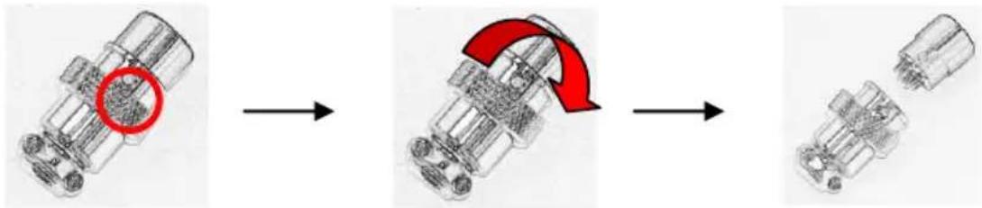
natural_image
Three-step diagram showing a mechanical assembly process with a red arrow indicating a curved transition (no text or symbols present)- Remove the screw
- Rotate the black portion
- Black portion / silver portion
b.) Solder 3 wires 22AWG (0,33m ^2 ) to PORT 1, 2 & 4 of black portion.
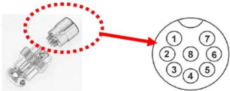
text_image
Diagram showing a connector pinout with numbered pins and a red arrow pointing to a circular component layout.Port numbers are marked on the black portion.
c.) Make sure the load is disconnected and the power supply is OFF.
d.) Plug the remote connector plug into the remote control terminal of the power supply.
e.) Secure the remote connector plug to the terminal socket by locking connector ring.

text_image
Outer ringThen, you can choose either method A or B below to use the remote control feature:
Method A:
Using Voltage Source
A variable external voltage source of 0 – 5 V is fed into the remote control terminal to adjust the output voltage level.
Warning:
Do not input higher than 5 V, otherwise the Over Voltage Protection (OVP) will be triggered.
- Make sure the load is disconnected and the power supply is OFF.
- Use only wires from port 2 and 4. Then, connect port 2 to positive polarity of the external voltage source and port 4 to negative polarity of the external voltage source.
- Switch on the power supply.
- Vary the external input voltage 0 – 5 V to check and verify for the full output voltage range of power supply.
- Switch off the power supply.
Method B:
Using 5 kΩ Variable Resistor
- Make sure the load is disconnected and the power supply is OFF.
- Prepare a 5 kΩ variable resistor and use wires from port 1, 2 and 4.
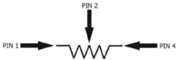
text_image
PIN 2 PIN 1 → ———————← PIN 4- Switch on the power supply.
- Adjust the 5 kΩ variable resistor from one end to other end to check and verify for the full output voltage range of power supply.
- Switch off the power supply.
9.4 Remote control of voltage control
a.) Using the same connector plug in section 9.1. Remove the black portion of the remote control connector plug by removing the screw.
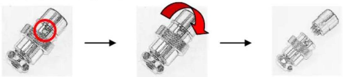
flowchart
graph LR
    A["Initial Component"] --> B["Assembly Step 1"]
    B --> C["Assembly Step 2"]
    C --> D["Final Assembly"]
- Remove the screw
- Rotate the black portion
- Black portion / silver portion
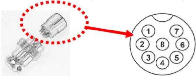
b.) Solder 3 wires 22AWG (0,33m ^2 ) to PORT 1, 3 & 4 of black portion as shown.
text_image
Diagram showing a connector pinout with numbered pins and a red arrow pointing to a circular component layout.Port numbers are marked on the black portion.
c.) Make sure the load is disconnected and the power supply is OFF.
d.) Plug the remote connector plug into the remote control terminal of the power supply.
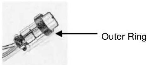
e.) Secure the remote connector plug to the terminal socket by locking connector ring.
text_image
Outer RingThen, you can choose either method A or B below to use the remote control feature:
Method A:
Using Voltage Source
A variable external voltage source of 0 – 5 V is fed into the remote control terminal to adjust the output voltage level.
Warning:
Do not input higher than 5 V, otherwise it may damage the unit.
- Make sure the load is disconnected and the power supply is OFF.
- Use Only wires from port 3 and 4. Then, connect port 3 to positive polarity of the external voltage source and port 4 to negative polarity of the external voltage source.
- Use a 8AWG (8,35mm ^2 ) wire to short circuit the main output terminal in the rear panel.
- Switch on the power supply.
- Vary the external input voltage 0 – 5 V to check and verify for the full output current range of power supply.
- Switch off the power supply and disconnect the 8AWG (8,35mm ^2 ) wire.
Method B:
Using 5 kΩ variable Resistor
- Make sure the load is disconnected and the power supply is OFF.
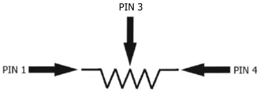
- Prepare a 5 kΩ variable resistor and use wires from port 1, 3 and 4.
text_image
PIN 3 PIN 1 PIN 4-
Use a 8AWG (8,35mm2) wire to short circuit the main output terminal in the rear panel.3.
-
Switch on the power supply.
-
Adjust the 5 kΩ variable resistor from one end to other end to check and verify for the full output current range of power supply.
-
Switch off the power supply and disconnect the 8AWG (8,35mm2) wire.
9.5 Remote control (P 1530/ 1560)
There are two methods for remote control of current and voltage adjustment. Both methods require current remote control part to be set up in order for remote control mode to be functional, otherwise unit will be in CC mode all the time.
Method A:
Using two external variable DC voltage sources.
| PIN | Function | Remarks |
| 1 | Internal DC +5V | Less the 50mA |
| 2 | Voltage Adjust | 0 ~ 5 V |
| 3 | Current Adjust | 0 ~5 V |
| 4 | Ground | |
| 5 | Output OFF | Short to Ground |
| 6 | N.A. | |
| 7 | N.A. | |
| 8 | N.A. |
Check the output voltage range of the power supply by varying the external voltage source.
Short circuit the main output with 8AWG (8,35mm2) wire to check the display for CC setting varying the external voltage source.
Method B:
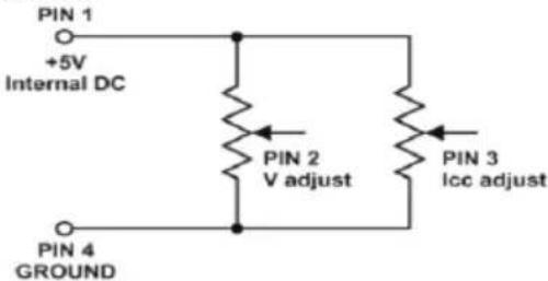
Using two 0-5K Ohm variable resistors
text_image
PIN 1 +5V Internal DC PIN 2 V adjust PIN 3 Icc adjust PIN 4 GROUNDRemark: variable resistors 5KOhm
| PIN | Function | Remarks |
| 1 | Internal DC +5V | Resistor end |
| 2 | Voltage Adjust | Variable part of resistor V |
| 3 | Current Adjust | Variable part of resistor |
| 4 | Ground | Another resistor end |
| 5 | Output OFF | Short to Ground |
| 6 | N.A. | |
| 7 | N.A. | |
| 8 | N.A. |
Check the output voltage range of the power supply by adjusting the 5Kohm variable resistor. Short circuit the main output with 8AWG (8,35mm2) wire to check the display for CC setting by adjusting the variable resistor.
- Specifications
| Model | P 1525 | P 1530 | P 1535 | P 1560 |
| Output | ||||
| Variable output voltage | 1 – 16V DC | 1 – 16V DC | 1 – 32V DC | 1 – 32V DC |
| Variable output current | 0 - 40A | 0 – 60 A | 0 - 20A | 0 – 30A |
| Voltage regulation | ||||
| Load (0-100%) | 50mV | |||
| Line (170 – 264V AC variation) | 20mV | |||
| Current regulation | ||||
| Load (10-90%) | 150mA | 200mA | 100mA | 40mA |
| Line (170 – 264V AC variation) | 50mA | |||
| Ripple & Noise | ||||
| Ripple & Noise voltage (rms) | 5mV | |||
| Ripple & Noise voltage (peak-peak) | 50mV | |||
| Ripple & Noise current (rms) | 70mA | 100mA | 30mA | 40mA |
| Meter Type & Accuracy | ||||
| voltage meter | 3 digit LED Display (+/-0,2% + 3 dgt.) | |||
| current meter | 3 digit LED Display (+/-0,2% + 3 dgt.) | |||
| Other | ||||
| Input voltage | 220 – 240V AC 50/60Hz | |||
| Full load input current | 3,15A | 4,7A | 3,1A | 4,5A |
| Efficiency | 85,50% | 85,00% | 87,00% | 86,00% |
| Switching frequency | 65 - 85kHz | 65 - 85kHz | 75 - 85kHz | 75 - 95kHz |
| Transient Response Time (50-100%) | 1,5ms | |||
| Power Factor Control (PFC) | Power factor correction >0,95 at optimal load | |||
| Cooling Method | Thermostatic Control Fan from Zero to full speed | |||
| Protections | Overload, Short Circuit by Constant Current, Output Tracking Over Voltage, Over Temperature | |||
| Special Features | 3 User defined VI preset, Remote control V, I and output on-off | |||
| Operating Temperature | 0 ... +50°C; RH < 70 % | |||
| Storage Temperature | -10 ... +60°C; RH < 80 % | |||
| Dimensions (WxHxD) in mm | 200x90x255 | 200x90x325 | 200x90x255 | 200x90x315 |
| Weight | 2,6kg | 3,2kg | 2,6kg | 3,2kg |
11. Trouble shooting
11.1 OVP: Over voltage protection
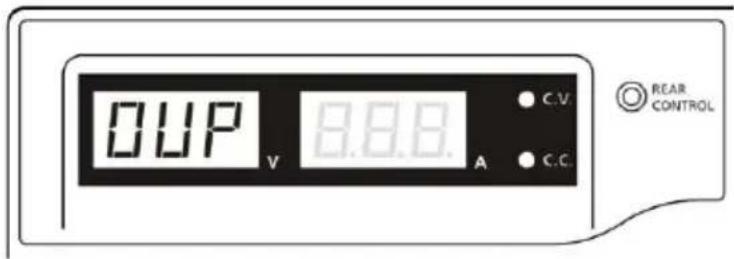
This unit has a built-in tracking over voltage protection feature. In the event of output voltage becoming greater than the set value (see specified range from specifications table), protection will be triggered and the output power will be cut off and OUP warning appears as below.
text_image
DUP V 8.8.8. A C.V. C.C. REAR CONTROLTo reset the warning, switch off the unit and remove all loading. Switch the unit back on again and it should resume normal operation. If this problem persists, please contact and consult with your agent.
11.2 OTP: Over temperature protection
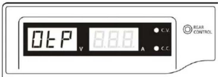
There is a thermo sensor inside the unit to monitor and to prevent the unit to gets too hot inside. At OTP, there is no output and the following warning will appear on the LED display. When you get this warning, switch off the unit and remove all loading.
text_image
0°C P V 8.8.8 A C.V. C.C. REAR CONTROLCheck your load and output setting. Allow the unit to cool down for at least 30 minutes. Check if any of the ventilation is blocked, check enough clearance around power supply. Listen carefully for the short wind noise from the cooling fan when you turn on the unit again. If you cannot hear this routine self test wind noise on switch on, the fan is fault and do not use the power supply, contact your agent.
11.3 OLP: Overload protection
Normally the overload protection is sustained by the CC constant current mode.
When the CC mode fails and goes undetected, it may cause serious damage to your test piece or load.
The OLP is to minimize the extent of damage to your loads as power supplies do fail some day.
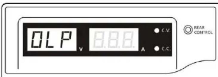
Switch off your power supply as soon as you see this warning as shown below.
text_image
OLP V 8.8.8. A C.V. C.C. REAR CONTROLTo reset this warning, switch off the unit and remove all loading.
Switch the unit back on again and double check with caution.
If this problem cannot be fixed, please contact and consult with your agent.
All rights, also for translation, reprinting and copy of this manual or parts are reserved.
Reproduction of all kinds (photocopy, microfilm or other) only by written permission of the publisher. This manual considers the latest technical knowing. Technical changing which are in the interest of progress reserved.
We herewith confirm, that the units are calibrated by the factory according to the specifications as per the technical specifications. We recommend to calibrate the unit again, after one year.
© PeakTech ^® 03/2021/MP/Lie/Ehr