
MAT20CSAWW - Washing machine MAYTAG - Free user manual and instructions
Find the device manual for free MAT20CSAWW MAYTAG in PDF.

| Product Type | Commercial Washing Machine |
| Brand | Maytag |
| Model | MAT20CSAWW |
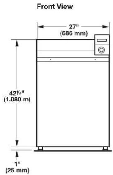
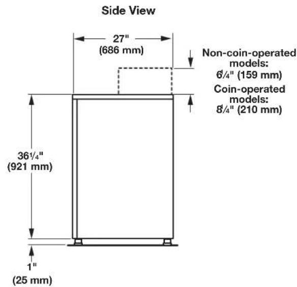
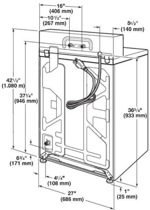
| Dimensions (H × W × D) | 42½" × 27" × 36½" (1080 × 686 × 921 mm) (non-coin model) |
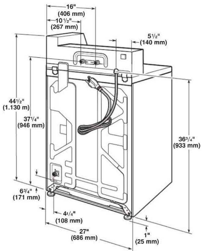
| Height with slide (coin model) | 44½" (1130 mm) |
| Maximum load weight | 315 lb (143 kg) |
| Power supply | 120 V, 60 Hz, 15 or 20 A, AC only |
| Plug type | 3-prong grounded |
| Required water pressure | 20 to 100 psi (138 to 690 kPa) |
| Recommended water temperature | Water heater set to 120°F (49°C) |
| Minimum drain capacity | 10 gal (38 L) per minute |
| Wash cycles | POWER WASH, MIXED, DELICATES, NORMAL ECO |
| Options | Temperature, soil level, extra rinse |
| Payment system | Coins or debit card (depending on model) |
| Default cycle prices | POWER WASH: $2.50, MIXED: $2.00, DELICATES: $1.75, NORMAL ECO: $1.75 (25¢ per coin) |
| Drum materials | Stainless steel (not explicitly specified, but standard) |
| Door lock feature | Yes (for coin models with slide) |
| Maintenance | Regular cleaning, replace inlet hoses every 5 years |
| Safety | Grounding, locked lid, automatic shut-off |
| Warranty | 5 years parts (labor excluded) |
| Optional accessories | Anti-siphon, hose extension, drip tray |
| Repairability | Spare parts available through authorized dealer |
| Certifications | Complies with US and Canadian standards |
Frequently Asked Questions - MAT20CSAWW MAYTAG
User questions about MAT20CSAWW MAYTAG
0 question about this device. Answer the ones you know or ask your own.
Ask a new question about this device
Download the instructions for your Washing machine in PDF format for free! Find your manual MAT20CSAWW - MAYTAG and take your electronic device back in hand. On this page are published all the documents necessary for the use of your device. MAT20CSAWW by MAYTAG.
USER MANUAL MAT20CSAWW MAYTAG
INSTALLATION INSTRUCTIONS
COMMERCIAL WASHER
INSTRUCTIONS D'INSTALLATION
LAVEUSE COMMERCIALE
TABLE OF CONTENTS
Page
Washer Safety....2
Tools & Parts....3
Dimensions 4
Location Requirements....5
Installation instructions 6
Level Washer....7
Connect Drain Hose....8
Drain System....9
Connect Inlet Hoses....10
Electrical Requirements....11
Complete Installation....12
Installing Coin Slide and Coin Box....12
Typical Full Load Sizes....12
Washer Maintenance....13
If You Need Assistance....14
Alternate Parts & Accessories 14
Electronic Controls Set-Up Instructions....15
Warranty....19
TABLE DES MATIÈRES
Page
Your safety and the safety of others are very important.
We have provided many important safety messages in this manual and on your appliance. Always read and obey all safety messages.

This is the safety alert symbol.
This symbol alerts you to potential hazards that can kill or hurt you and others.
All safety messages will follow the safety alert symbol and either the word "DANGER" or "WARNING."
These words mean:
! DANGER
You can be killed or seriously injured if you don't immediately follow instructions.
WARNING
You can be killed or seriously injured if you don't follow instructions.
All safety messages will tell you what the potential hazard is, tell you how to reduce the chance of injury, and tell you what can happen if the instructions are not followed.
IMPORTANT SAFETY INSTRUCTIONS
WARNING: To reduce the risk of fire, electric shock, or injury to persons when using the washer, follow basic precautions, including the following:
■ Read all instructions before using the washer.
■ Do not wash articles that have been previously cleaned in, washed in, soaked in, or spotted with gasoline, dry-cleaning solvents, other flammable, or explosive substances as they give off vapors that could ignite or explode.
■ Do not add gasoline, dry-cleaning solvents, or other flammable, or explosive substances to the wash water. These substances give off vapors that could ignite or explode.
■ Under certain conditions, hydrogen gas may be produced in a hot water system that has not been used for 2 weeks or more. HYDROGEN GAS IS EXPLOSIVE. If the hot water system has not been used for such a period, before using the washing machine, turn on all hot water faucets and let the water flow from each for several minutes. This will release any accumulated hydrogen gas. As the gas is flammable, do not smoke or use an open flame during this time.
■ Do not allow children to play on or in the washer. Close supervision of children is necessary when the washer is used near children.
■ Before the washer is removed from service or discarded, remove the door or lid.
■ Do not reach into the washer if the drum, tub or agitator is moving.
■ Do not install or store the washer where it will be exposed to the weather.
■ Do not tamper with controls.
■ Do not repair or replace any part of the washer or attempt any servicing unless specifically recommended in this manual or in published user-repair instructions that you understand and have the skills to carry out.
■ See "Electrical Requirements" located in the installation instructions for grounding instructions.
SAVE THESE INSTRUCTIONS
FOR YOUR SAFETY
Do not store or use gasoline or other flammable vapors and liquids in the vicinity of this or any other appliance.
State of California Proposition 65 Warnings:
WARNING: This product contains one or more chemicals known to the State of California to cause cancer.
WARNING: This product contains one or more chemicals known to the State of California to cause birth defects or other reproductive harm.
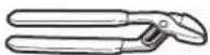
Tools Needed:
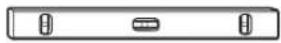
Level Pliers

Utility Knife

9/16" (14 mm)
Open-End Wrench
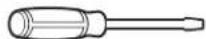
Flat-Blade Screwdriver
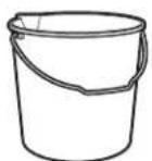
Optional tools:

Flashlight Bucket
Parts Supplied:
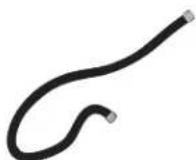
Water Inlet Hoses (2) Inlet Hose Washers (4)

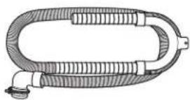
Drain Hose with Clamp, U-Form, and Cable Tie
Back View
Non-coin-operated models Coin-operated models
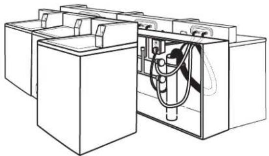
Selecting the proper location for your washer improves performance and minimizes noise and possible washer "walk."
Your washer can be installed in a basement, laundry room, or recessed area. See "Drain System."
Companion appliance location requirements should also be considered.
IMPORTANT: Do not install or store the washer where it will be exposed to the weather. Do not store or operate the washer in temperatures at or below 32^ F ( 0^ C). Some water can remain in the washer and can cause damage in low temperatures. Proper installation is your responsibility.
You will need:
■ A water heater set to 120^ F ( 49^ C).
A grounded electrical outlet located within 4 ft. (1.2 m) of power cord on back of washer. See "Electrical Requirements."
Hot and cold water faucets located within 4 ft. (1.2 m) of hot and cold water fill valves on washer, and water pressure of 20–100 psi (138–690 kPa). A pressure reduction valve should be used in the supply line where inlet pressure entering the building exceeds 100 PSI (690 kPa) to avoid damage to the washer mixing valve.
■ Single washer installations require 12" (300 mm) minimum risers to provide an air cushion and avoid noise and damage to valves.
A level floor with maximum slope of 1" (25 mm) under entire washer. Installing on carpet is not recommended.
Floor must support washer's total weight (with water and load) of 315 lbs (143 kgs).
A floor drain under the bulkhead. Prefabricated bulkheads with electrical outlets, water inlet lines, and drain facilities should be used only where local codes permit.
natural_image
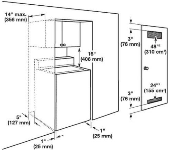
Line drawing of a battery pack with internal circuit and wiring (no text or symbols)Recessed Area or Closet Installation
This washer may be installed in a recessed area or closet. The installation dimensions shown are the minimum spaces allowable. Additional spacing should be considered for ease of installation and servicing. If closet door is installed, the minimum air openings in top and bottom of door are required. Louvered doors with air openings in top and bottom are acceptable. Companion appliance spacing should be considered.
Minimum installation spacing
WARNING
Excessive Weight Hazard
Use two or more people to move and install washer.
Failure to do so can result in back or other injury.
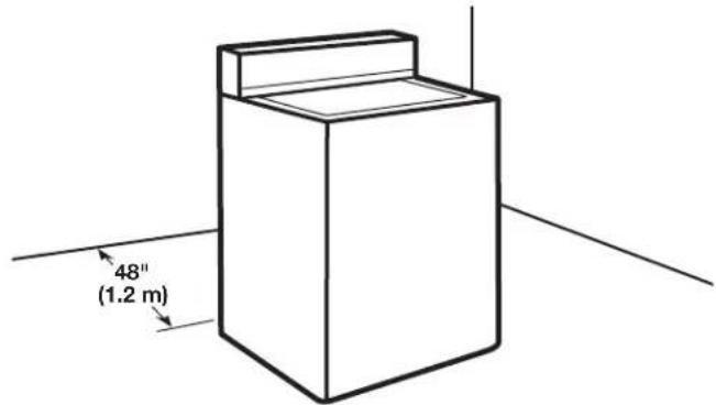
It is necessary to remove all shipping materials for proper operation and to avoid excessive noise from washer.
- Move washer to within 4 ft (1.2 m) of its final location; it must be in a fully upright position.
NOTE: To avoid floor damage, set washer onto cardboard before moving it and make sure lid is taped shut.
- To avoid damaging floor, place cardboard supports from shipping carton on floor behind washer. Tip washer back and place on cardboard supports. Remove shipping base. Set washer upright.
IMPORTANT: Removing shipping base is necessary for proper operation.
NOTE: Keep shipping base in case you need to move washer later.

natural_image
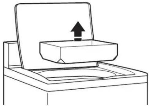
Diagram showing two views of a mechanical device with arrows indicating motion or transformation (no text or symbols present)- Remove tape from washer lid, open lid, and remove cardboard packing tray from tub. Be sure to remove all parts from tray.
NOTE: Keep tray in case you need to move washer later.
natural_image
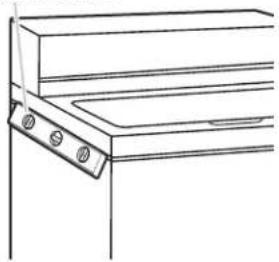
Simple line drawing of a printer or printer with an upward arrow indicating compression or lifting (no text or symbols)IMPORTANT: Level washer properly to reduce excess noise and vibration.
WARNING
Excessive Weight Hazard
Use two or more people to move and install washer.
Failure to do so can result in back or other injury.
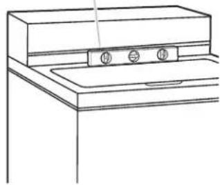
- Move the washer to its final location. Place a level on top edges of washer. Use side seam as a guide to check levelness of sides. Check levelness of front using lid, as shown. Rock washer back and forth to make sure all four feet make solid contact with floor.
Placeed well frame
natural_image
Line drawing of a mechanical bracket or bracket with mounting holes and a handle (no text or symbols)Place level here
natural_image
Line drawing of a kitchen sink with a double-burner top (no text or symbols)
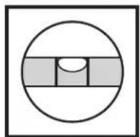
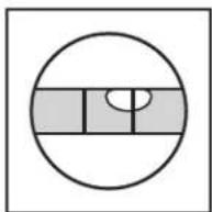
Not Level LEVEL Not Level
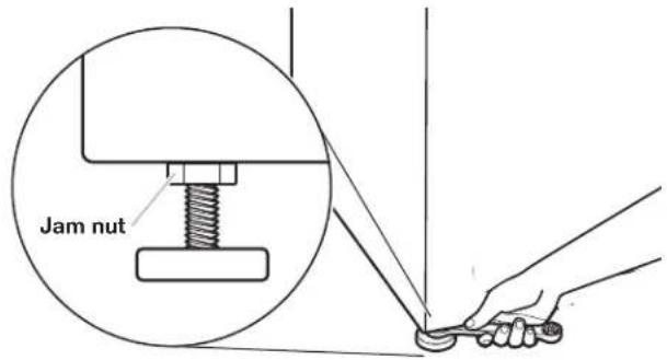
- Use a 9/16" or 14 mm open-end or adjustable wrench to turn jam nuts clockwise on feet until they are about 1/2" (13 mm) from the washer cabinet. Then turn the leveling foot clockwise to lower the washer or counterclockwise to raise the washer. Recheck levelness of washer and repeat as needed.
HELPFUL TIP: You may want to prop up front of washer about 4" (102 mm) with a wood block or similar object that will support weight of washer.
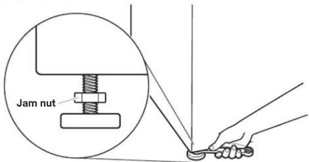
- When washer is level, use a 9/16" or 14 mm open-end or adjustable wrench to turn jam nuts counterclockwise on leveling feet tightly against washer cabinet.
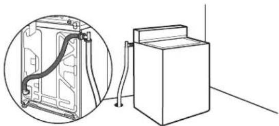
CONNECT DRAIN HOSE
Proper routing of the drain hose avoids damage to your floor due to water leakage.
Remove drain hose from the washer basket
- Remove cap from the washer drain port on the back of the washer.
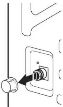
natural_image
Diagram showing a connector inserted into a socket (no text or symbols present)- If clamp is not already in place on elbow end of drain hose, slide it over end as shown.
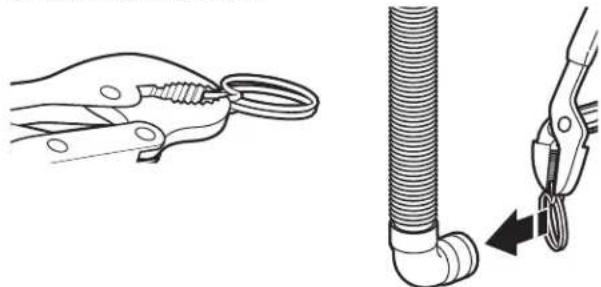
natural_image
Illustration showing a hand holding a coiled wire and a flexible hose with a coiled tube, alongside a close-up of the cable being inserted (no text or symbols present)- Squeeze clamp with pliers and slide elbow end of drain hose onto washer drain port and secure with clamp.
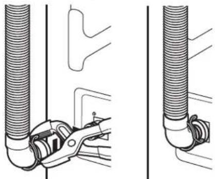
natural_image
Technical line drawing of a mechanical assembly with coiled pipes and clamps (no text or symbols)-
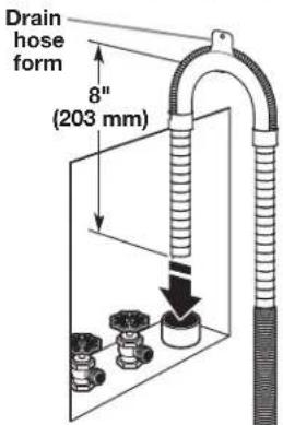
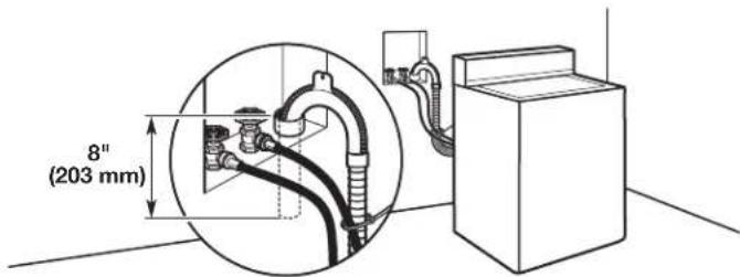
The washer drain system can be installed using a floor drain, wall standpipe, floor standpipe, or laundry tub.
-
Place hose into standpipe (shown in picture) or over side of laundry tub.
IMPORTANT:
Drain hose is not to exceed 8" (203 mm) into drain pipe; do not force excess hose into standpipe or lay on bottom of laundry tub. Drain hose form must be used.
It is the responsibility of the installer to install and secure the drain hose into the provided plumbing/drain in a manner that will avoid the drain hose coming out of, or leaking from, the plumbing/drain.
natural_image
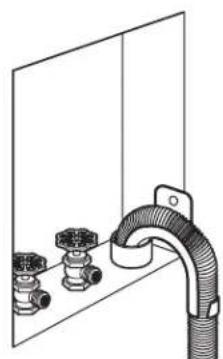
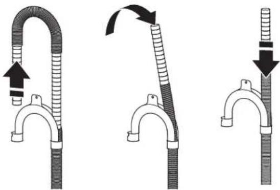
Diagram of a pipe fitting attached to a wall-mounted valve, showing three fittings and a connecting rod (no text or labels)- For floor drain installations, you will need to remove the drain hose form from the end of the drain hose. You may need additional parts with separate directions. See "Tools and Parts."
natural_image
Three-step diagram showing a flexible hose being inserted into a bent tube, with arrows indicating direction of movement (no text or symbols present)- The floor drain system requires a siphon break that may be purchased separately. The siphon break (Part Number 285320) must be a minimum of 28" (710 mm) from the bottom of the washer. Additional hoses might be needed.
Drain system can be installed using a floor drain, wall standpipe, floor standpipe, or laundry tub. Select method you need.
Floor standpipe drain system
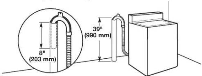
Minimum diameter for a standpipe drain: 2" (51 mm). Minimum carry-away capacity: 10 gal. (38 L) per minute. Top of standpipe must be at least 39" (990 mm) high; install no higher than 96" (2.44 m) from bottom of washer.
Wall standpipe drain system
See requirements for floor standpipe drain system.
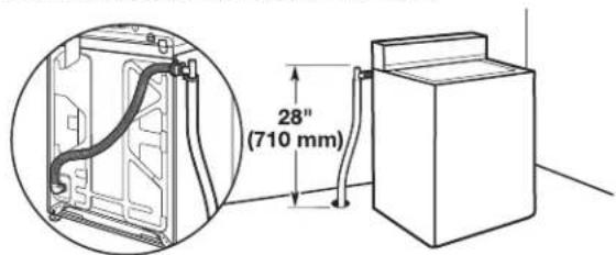
Floor drain system
natural_image
Line drawing of a refrigerator with attached electrical outlet and close-up view of internal components (no text or symbols)Floor drain system requires a Siphon Break Kit (Part Number 285320). Minimum siphon break: 28" (710 mm) from bottom of washer. Additional hoses may be needed.
Laundry tub drain system
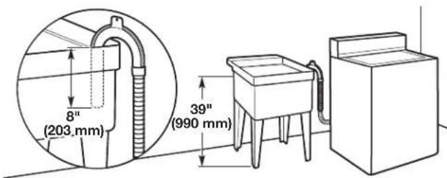
Minimum capacity: 20 gal. (76 L). The top of the laundry tub must be at least 39" (990 mm) above floor.
Insert new hose washers (supplied) into each end of the inlet hoses. Firmly seat the washers in the couplings.
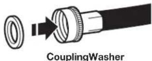
Connect Inlet Hoses to Water Faucets
- Attach hose to hot water faucet. Screw on coupling until it is seated on washer. Repeat process for cold water.
natural_image
Diagram of pipe fittings and valves on a surface, showing connections without any text or symbols- Use pliers to tighten the couplings an additional two-thirds turn.
natural_image
Mechanical assembly diagram showing hands operating a chain with rotating arrows indicating motion (no text or symbols)IMPORTANT: Do not overtighten or use tape or sealants on valve when attaching to faucets or washer. Damage can result.
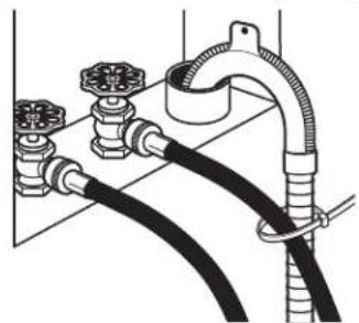
- Secure drain hose to inlet hose with zip strap.
natural_image
Diagram of a flexible hose assembly with multiple valves and tubing (no text or labels)Clear Water Lines
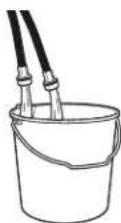
■ Run water through both faucets and inlet hoses, into a laundry tub, drainpipe, or bucket to get rid of particles in the water lines that might clog the inlet valve screens.
Check the temperature of the water to make sure that the hot water hose is connected to the hot water faucet and that the cold water hose is connected to the cold water faucet.
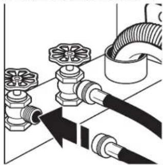
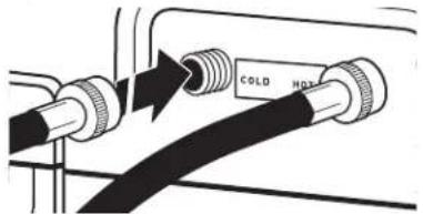
Connect Inlet Hoses to Washer
- Attach cold water hose to cold water inlet valve marked with a blue ring. Screw coupling by hand until it is snug.
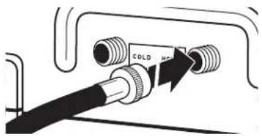
- Attach hot water hose to hot water inlet valve marked with a red ring. Screw coupling by hand until it is snug.
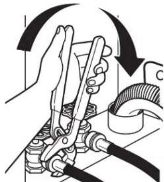
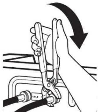
- Use pliers to tighten couplings an additional two-thirds turn.
natural_image
Illustration of a hand using a lift tool to lift a cable, with no text or symbols present.NOTE: Do not overtighten. Damage to the valve can result.
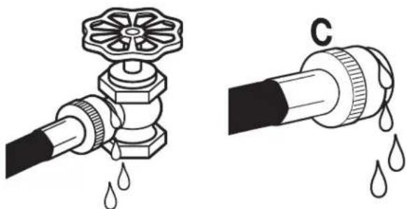
- Turn on water faucets to check for leaks. A small amount of water may enter washer. It will drain later.
natural_image
Illustration of two different types of plumbing fittings: a valve with liquid drop and a hose with water droplets (no text or symbols)NOTE: Replace inlet hoses after 5 years of use to reduce the risk of hose failure. Record hose installation or replacement dates on the hoses for future reference.
Periodically inspect and replace hoses if bulges, kinks, cuts, wear, or leaks are found.
⚠ WARNING

Electrical Shock Hazard
Plug into a grounded 3 prong outlet.
Do not remove ground prong.
Do not use an adapter.
Do not use an extension cord.
Failure to follow these instructions can result in death, fire, or electrical shock.
A 120-volt, 60 Hz., AC-only, 15- or 20-amp, fused electrical supply is required. A time-delay fuse or circuit breaker is recommended. It is recommended that a separate circuit breaker serving only this appliance be provided.
■ This washer is equipped with a power supply cord having a 3 prong grounding plug.
To minimize possible shock hazard, the cord must be plugged into a mating, 3 prong, grounding-type outlet, grounded in accordance with local codes and ordinances. If a mating outlet is not available, it is the personal responsibility and obligation of the customer to have the properly grounded outlet installed by a qualified electrician.
If codes permit and a separate ground wire is used, it is recommended that a qualified electrician determine that the ground path is adequate.
■ Do not ground to a gas pipe.
- Check with a qualified electrician if you are not sure the washer is properly grounded.
■ Do not have a fuse in the neutral or ground circuit.
GROUNDING INSTRUCTIONS
For a grounded, cord-connected washer:
This washer must be grounded. In the event of a malfunction or breakdown, grounding will reduce the risk of electrical shock by providing a path of least resistance for electric current. This washer is equipped with a cord having an equipment-grounding conductor and a grounding plug. The plug must be plugged into an appropriate outlet that is properly installed and grounded in accordance with all local codes and ordinances.
WARNING: Improper connection of the equipment-grounding conductor can result in a risk of electric shock. Check with a qualified electrician or serviceman if you are in doubt as to whether the appliance is properly grounded.
Do not modify the plug provided with the appliance – if it will not fit the outlet, have a proper outlet installed by a qualified electrician.
For a permanently connected washer:
This washer must be connected to a grounded metal, permanent wiring system, or an equipment grounding conductor must be run with the circuit conductors and connected to the equipment-grounding terminal or lead on the appliance.
WARNING

Electrical Shock Hazard
Plug into a grounded 3 prong outlet.
Do not remove ground prong.
Do not use an adapter.
Do not use an extension cord.
Failure to follow these instructions can result in death, fire, or electrical shock.
☐ Check that all parts are now installed. If there is an extra part, go back through steps to see what was skipped.
☐ Check that you have all of your tools.
☐ Check that shipping materials were completely removed from washer.
☐ Dispose of/recycle all packaging materials.
☐Check that the water faucets are on.
☐ Check for leaks around faucets and inlet hoses.
☐ Remove film from console and any tape remaining on washer.
Plug into a grounded outlet or connect power.
☐ Check that circuit breaker is not tripped or fuse is not blown.
☐ Start the washer using the payment system if used and check that the washer completes the cycle without a fault or water leak.
☐ Check electrical requirements. Be sure that you have the correct electrical supply and the recommended grounding method.
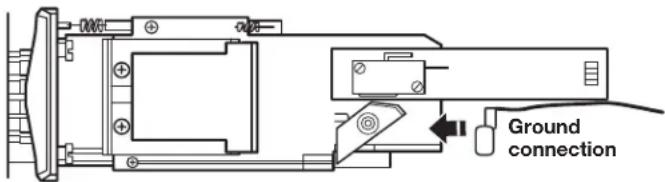
INSTALLING COIN SLIDE AND COIN BOX
The coin slide mechanism, service door lock and key, and coin box lock and key are not included with some models, but can be obtained from the usual industry sources.
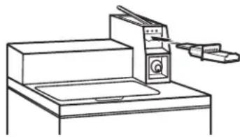
Remove the service door of the meter case by lifting it up at the back. Install the money-accepting device. (Refer to manufacturer's instructions for proper installation.)
A ground connection is needed for the coin slide, which can be made by connecting the available harness (W10846503) to the coin slide.
natural_image
Line drawing of a mechanical device with a clamp and base plate (no text or symbols)Install a lock and cam on the meter case service door. Install the coin vault with lock and key in the meter case opening.
TYPICAL FULL LOAD SIZES
| Load Type Loading Suggestion | Load Type Loading Suggestion | ||
| Mixed Load 3 double sheets | 4 pillowcases6 pair shorts8 T-shirts2 shirts2 blouses8 handkerchiefs | Heavy Work Clothes 3 pair pants | 3 shirts1 coverall4 pair jeans1 overall |
| Permanent Press 2 double or | 1 king size sheet1 tablecloth1 dress1 blouse2 slacks3 shirts2 pillowcases | Knits 3 blouses | 4 slacks6 shirts4 tops4 dresses |
Operating Tips
WARNING

Fire Hazard
Never place items in the washer that are dampened with gasoline or other flammable fluids.
No washer can completely remove oil.
Do not dry anything that has ever had any type of oil on it (including cooking oils).
Doing so can result in death, explosion, or fire.
It is recommended that fiberglass items not be washed in coin-operated washers. If these items are washed in the washer, run the washer through a complete cycle to rinse any residue away that might be left in the washer.
Transporting Your Washer
■ Shut off both water faucets. Disconnect and drain water inlet hoses.
■ Disconnect drain from drain system and drain any remaining water into a pan or bucket. Disconnect drain hose from back of washer.
■ Unplug power cord.
■ Place inlet hoses and drain hose inside washer basket.
■ Drape power cord over edge and into washer basket.
Place packing tray from original shipping materials back inside washer and reuse shipping base to support the motor and tub. If you do not have original packaging, place heavy blankets or towels above basket, between the washer top and the tub ring. Close lid and place tape over lip and down the front of the washer. Keep lid taped until washer is moved to new location.
IF YOU NEED ASSISTANCE
Contact your authorized Commercial Laundry distributor. To locate your authorized Commercial Laundry distributor, or for web inquiries, visit www.MaytagCommercialLaundry.com.
If you cannot locate your distributor, the Commercial Laundry Support Center will answer any questions about operating or maintaining your washer not covered in the Installation Instructions.
Just dial 1-800-662-3587 — the call is toll free.
When you call, you will need the washer model number and serial number. Both numbers can be found on the serial-rating plate located on the washer.
ALTERNATE PARTS & ACCESSORIES
Your installation may require additional parts. If you are interested in purchasing one of the items listed here, call the toll-free number in the "If You Need Assistance" section.
| If You Have: You Will Need: | |
| Overhead sewer Standard 20 | gal. (76 L) 39"(990 mm) tall drain tub or utility sink, sump pump and connectors (available from local plumbing suppliers) |
| 1" (25 mm) standpipe 2" (51 | mm) diameter to1" (25 mm) diameter Standpipe Adapter Part Number 3363920 Connector Kit Part Number 285835 |
| Lint clogged drain Drain Protector | ector Part Number367031 Connector Kit Part Number 285835 |
| Floor drain system Siphon break, Part Number285320 Connector Kit (x2) Part Number 285835 Extension Drain Hose Part Number 285863 | |
| Water faucets beyond reach of fill hoses | 2 longer water fill hoses:6 ft. (1.8 m) 90° bend hosePart Number 76314, 10 ft. (3.0 m)Part Number 350008 |
| Inlet hoses are sold as a pair in kit W10575888 | |
| Accessories | |
| Washer Drip TraysPart Number 8212526 | |
| Fabric Softener Dispenser KitPart Number 63594 | |
| Drain beyond reach of drain hose | 4 ft. (1.2 m) Drain Hose Extension Part Number DRNEXT4 |
Whirlpool Corporation, Benton Harbor, Michigan 49022, U.S.A.
ELECTRONIC CONTROLS SET-UP INSTRUCTIONS
Basic Operation of Commercial Washer
■ For additional information, see www.MaytagCommercialLaundry.com.

WARNING
Electrical Shock Hazard
Disconnect power before servicing.
Replace all parts and panels before operating.
Failure to do so can result in death or electrical shock.
IMPORTANT
Electrostatic Discharge (ESD) Sensitive Electronics
ESD problems are present everywhere. ESD may damage or weaken the electronic control assembly. The new control assembly may appear to work well after repair is finished, but failure may occur at a later date due to ESD stress.
■ Use an anti-static wrist strap. Connect wrist strap to green ground connection point or unpainted metal in the washer.
-OR-
Touch your finger repeatedly to a green ground connection point or unpainted metal in the washer.
■ Before removing the part from its package, touch the anti-static bag to a green ground connection point or unpainted metal in the washer.
- Avoid touching electronic parts or terminal contacts; handle electronic control assembly by edges only.
■ When repackaging failed electronic control assembly in anti-static bag, observe above instructions.
Free Cycles
This is established by setting the cycle price to zero. When this happens, 'SELECT CYCLE' will appear and cycle price will show 0.00.
Debit Card Ready
This washer is debit card 'cable' ready. It will accept a variety of debit card systems, but does NOT come with a debit card reader. Refer to the debit card reader manufacturer for proper washer setup. In models converted to a Generation 1 debit card system, debit pulses represent the equivalent of one coin (coin 1).
Display
After the washer has been installed and plugged in, the display will show 'SYnC' for a few seconds, then '0 MINUTES'. Once the washer has been plugged in and the washer door opened and closed, the display will show the price. In washers set for free cycles, the display will flash 'SELECT CYCLE', and will display 'PRICE 0.00'.
GENERAL INFORMATION
Blank Display
This condition indicates the washer is inoperative.
'0 Minutes' showing in display
This condition indicates the washer cannot be operated. Coins dropped or debit inputs during this condition will be stored in escrow but cannot be used until normal operation is restored by opening and closing the door. If a door switch fails, it must be replaced before normal operation can be restored.
Cold Start (initial first use)
Washer is programmed at the factory as follows:
■ POWERWASH = 12 min agitation
MIXED = 9 min agitation
DELICATES = 6 min agitation
NORMAL ECO = 8 min agitation
■ MIXED = 1 rinse and 2 minutes of rinse agitation
POWERWASH = 1 deep rinse with spin out
DELICATES = 1 deep rinse with spin out
NORMAL ECO = 1 spray rinse
■ MIXED = \$2.00
DELICATES = \$1.75
POWERWASH = \$2.50
NORMAL ECO = \$1.75
Warm Start (after power failure)
After a delay of up to 8 seconds, the washer is restored to the portion of the cycle that existed at time of the power failure. To continue the cycle, press START.
ELECTRONIC CONTROLS SET-UP INSTRUCTIONS
Control Set-Up Procedures
IMPORTANT: Read all instructions before operating.
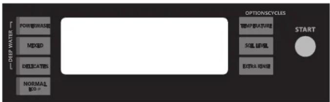
The lower fabric setting key pads and the digital display are used to set up the controls. The display can contain four numbers and/or letters and a decimal point. These are used to indicate the set-up codes and related code values available for use in programming the washer.
How to use the key pads to program the controls
- The POWERWASH key pad is used to adjust the values associated with set-up codes. Pressing the key pad will increment the value.
Rapid adjustment is possible by holding the key pad down.
-
The MIXED key pad will advance you through the set-up codes. Pressing the key pad will advance you to the next available set-up code. Holding the key pad down will automatically advance through the set-up codes at a rate of one (1) per second.
-
The DELICATES key pad is used to select or deselect options.
-
The TEMPERATURE key pad is used to decrease set-up code value.
Start Operating Set-Up
■ PD Models: Insert access door key, turn, and lift to remove access door.
■ PR models set for free vend: Refer to bottom of page 18 for entering operating setup.
PR Models: Once the debit card reader is installed (according to the reader manufacturer's instructions), the set-up mode can be entered by inserting a set-up card (supplied by the reader manufacturer) into the card slot. If a manual set-up card is not available, manual set-up mode can be entered by removing connector AA1 on the circuit board.
IMPORTANT: The console must not be opened unless power is first removed from the washer. To access connector AA1:
→ Unplug washer or disconnect power.
→ Open console, disconnect plug on AA1, close console.
→ Plug in washer or reconnect power.
The washer is now in the set-up mode.
Before proceeding, it is worth noting that, despite all of the options available, an owner can simply choose to uncrate a new commercial washer, hook it up, plug it in, and have a unit that operates.
Set-Up Codes
■ The MIXED key pad will advance from code to code.
■ The POWERWASH key pad will increase the code value.
■ The DELICATES key pad will select or deselect options.
■ The TEMPERATURE key pad will decrease the code value.
FOR PR MODELS: The set-up codes are the same as for the 'PD' models except where noted.
The set-up code is indicated by the one or two left-hand characters. The set-up code value is indicated by the two or three right-hand characters.
| CODE EXPLANATION | |
| 6.07 DELICATES | DELICATES Regular Cycle Vend Price - Increase or decrease between 0 and 200 by pressing the POWERWASH or TEMPERATURE key pad. Factory preset for 7 quarters = $1.75. PR/PN MODELS ONLY: Factory preset for 0 quarters (Free Vend). |
| CODE EXPLANATION | |
| 6.07NORMALECO | NORMAL ECO Regular Cycle Vend Price - Increase or decrease between 0 and 200 by pressing the POWERWASH or TEMPERATURE key pad. Factory preset for 7 quarters = 1.75.PR/PN MODELS ONLY: Factory preset for 0 quarters (Free Vend). |
| 6.07POWERWASH | POWERWASH Regular Cycle Vend Price - Increase or decrease between 0 and 200 by pressing the POWERWASH or TEMPERATURE key pad. Factory preset for 7 quarters =1.75.PR/PN MODELS ONLY: Factory preset for 0 quarters (Free Vend). |
| 6.08MIXED | MIXED Regular Cycle Vend Price - Increase or decrease between 0 and 200 by pressing the POWERWASH or TEMPERATURE key pad. Factory preset for 8 quarters = $2.00.PR/PN MODELS ONLY: Factory preset for 0 quarters (Free Vend). |
| → Press the MIXED key pad once to advance to next code. | |
| P.dEF | Default Cycle Price displayed in Standby - Increase or decrease between MIXED, DELICATES, POWERWASH, NORMAL ECO by pressing the POWERWASH or TEMPERATURE key pad. Factory preset for MIXED. |
| 7.00 | ADDITIONAL WASH TIME |
| 7.00 | This is the number of minutes that can be added to a Wash Cycle.Choose from 00-05 minutes by pressing the POWERWASH key pad. |
| → Press the MIXED key pad once to advance to next code. | |
| 8.00 | ADDITIONAL RINSE TIME |
| 8.00 | This is the number of minutes that can be added to a Rinse Cycle.Choose from 00-05 minutes by pressing the POWERWASH key pad. |
| → Press the MIXED key pad once to advance to next code. | |
| 9.00 | CYCLE COUNTER OPTIONThis option is either SELECTED 'ON' or NOT SELECTED 'OFF'. |
| 9.00 | Not Selected 'OFF'. |
| 9.0C | Selected 'ON' and not able to be deselected.Press the DELICATES key pad 3 consecutive times to select 'ON'.Once selected 'ON' it cannot be deselected. |
| → Press the MIXED key pad once to advance to next code. | |
| 1.00 | MONEY COUNTER OPTIONThis option is either SELECTED 'ON' or NOT SELECTED 'OFF'. |
| 1.00 | Not Selected 'OFF'. |
| 1.0C | Selected 'ON'.Press the DELICATES key pad 3 consecutive times to select 'ON' and 3 consecutive times to remove (Not Selected 'OFF'.) Counter resets by going from 'OFF' to 'ON'. |
| 1.CO | Selected 'ON' and not able to be deselected.To select 'ON' and not able to be deselected, first select 'ON', then within 2 seconds press the DELICATES key pad twice, the POWERWASH key pad once, and exit the set-up mode. |
| → Press the MIXED key pad once to advance to next code. | |
| 2.00 | SPECIAL PRICING OPTIONThis option is either SELECTED 'ON' or NOT SELECTED 'OFF'. |
| 2.00 | Not Selected 'OFF'. |
| 2.SP | Selected 'ON'. Press the DELICATES key pad once for this selection. |
| If SPECIAL PRICING OPTION is selected, there is access to codes '3.' through '9.'.NOTE: An external battery needs to be added to keep the clock running during periods of power outages.→ Press the MIXED key pad once to advance to next code. | |
ELECTRONIC CONTROLS SET-UP INSTRUCTIONS
| CODE EXPLANATION | ||
| OPTIONS TO USE IF SPECIAL PRICING IS SELECTED: | ||
| 3.07 DELICATES | DELICATES Special Cycle Vend Price - Increase or decrease between 0 and 200 by pressing the POWERWASH or TEMPERATURE key pad. Factory preset for 7 quarters = 1.75.PR/PN MODELS ONLY: Factory preset for 0 quarters (Free Vend). | |
| 3.07 Normal ECO | Normal ECO Special Cycle Vend Price - Increase between 0 and 200 by pressing the POWERWASH key pad and decrease by pressing the TEMPERATURE key pad. Factory preset for 7 quarters =1.75.PR/PN MODELS ONLY: Factory preset for 0 quarters (Free Vend). | |
| 3.07 POWERWASH | POWERWASH Special Cycle Vend Price - Increase or decrease between 0 and 200 by pressing the POWERWASH or TEMPERATURE key pad. Factory preset for 7 quarters = 1.75.PR/PN MODELS ONLY: Factory preset for 0 quarters (Free Vend). | |
| 3.08 MIXED | MIXED Special Cycle Vend Price - Increase or decrease between 0 and 200 by pressing the POWERWASH or TEMPERATURE key pad. Factory preset for 8 quarters =2.00.PR/PN MODELS ONLY: Factory preset for 0 quarters (Free Vend). | |
| → Press the MIXED key pad once to advance to next code. | ||
| 5.00 | TIME-OF-DAY CLOCK, MINUTES | |
| 5.00 | This is the TIME-OF-DAY CLOCK, minute setting; select between 0 and 59 minutes by pressing the POWERWASH or TEMPERATURE key pad. | |
| → Press the MIXED key pad once to advance to next code. | ||
| 6.00 | TIME-OF-DAY CLOCK, HOURSNOTE: Uses military time or 24 hr. clock. | |
| 6.00 | This is the TIME-OF-DAY CLOCK, hour setting; select between 0 and 23 hours by pressing the POWERWASH or TEMPERATURE key pad. | |
| → Press the MIXED key pad once to advance to next code. | ||
| 7.00 | SPECIAL PRICE START HOURNOTE: Uses military time or 24 hr. clock. | |
| 7.00 | This is the start hour; select between 0 and 23 hours by pressing the POWERWASH or TEMPERATURE key pad. | |
| → Press the MIXED key pad once to advance to next code. | ||
| 8.00 | SPECIAL PRICE STOP HOURNOTE: Uses military time or 24 hr. clock. | |
| 8.00 | This is the stop hour; select between 0 and 23 hours by pressing the POWERWASH or TEMPERATURE key pad. | |
| → Press the MIXED key pad once to advance to next code. | ||
| 9.00 | SPECIAL PRICE DAY | |
| 9.10 | This represents the day of the week and whether special pricing is selected for that day. A number followed by ‘0’ indicates no selection that particular day (9.10). A number followed by an ‘S’ indicates selected for that day (9.1S).Days of the week (1-7) can be chosen by pressing the POWERWASH key pad. Press the POWERWASH key pad once to select special pricing for each day chosen.When exiting set-up code ‘9’, the display must show current day of week: | |
| DISPLAY | DAY OF WEEK CODE (selected) | |
| 10 | Day 1 = Sunday 1S | |
| 20 | Day 2 = Monday 2S | |
| 30 | Day 3 = Tuesday 3S | |
| 40 | Day 4 = Wednesday 4S | |
| 50 | Day 5 = Thursday 5S | |
| 60 | Day 6 = Friday 6S | |
| 70 | Day 7 = Saturday 7S | |
| CODE EXPLANATION | |
| →Press the MIXED key pad once to advance to next code. | |
| A.00 | VAULT VIEWING OPTIONThis option is either SELECTED 'ON' or NOT SELECTED 'OFF'. |
| A.00 | Not Selected 'OFF'. |
| A.SC | Selected 'ON'. Press the DELICATES key pad once for this selection. When selected, the money and/or cycle counts will be viewable (depending on what is selected) when the coin box is removed. |
| →Press the MIXED key pad once to advance to next code. | |
| b.05 | VALUE OF COIN 1 |
| b.05 | This represents the value of coin 1 in number of nickels:05 = 0.25.By pressing the POWERWASH or TEMPERATURE key pad, there is the option of between 1 and 199 nickels. |
| →Press the MIXED key pad once to advance to next code. | |
| C.20 | VALUE OF COIN 2 |
| C.20 | This represents the value of coin 2 in number of nickels:20 =1.00.PR MODELS ONLY: Factory preset for 0.25.By pressing the POWERWASH or TEMPERATURE key pad, there is the option of between 1 and 199 nickels. |
| →Press the MIXED key pad once to advance to next code. | |
| d.00 | COIN SLIDE OPTIONThis option is either SELECTED 'ON' or NOT SELECTED 'OFF'. |
| d.00 | Not Selected 'OFF'. |
| d.CS | Selected 'ON'. Press the DELICATES key pad 3 consecutive times for this selection.When coin slide mode is selected, set 'b.' equal to value of slide in nickels. Set Step 6 (regular cycle price) and Step 3 (special cycle price) to number of slide operations. If the installer sets up 'CS' on a coin drop model, it will not register coins. |
| →Press the MIXED key pad once to advance to next code. | |
| E.00 | ADD COINS OPTIONThis option is either SELECTED 'ON' or NOT SELECTED 'OFF'.This option causes the customer display to show the number of coins (coin 1) to enter, rather than the dollars-and-cents amount. |
| E.00 | Not Selected 'OFF'. |
| E.AC | Selected 'ON'. Press the DELICATES key pad 3 consecutive times for this selection. |
| →Press the MIXED key pad once to advance to next code. | |
| H.00COLD | COLD Temperature Upgrade Price - Increase or decrease between 0 and 200 by pressing the POWERWASH or TEMPERATURE key pad. Factory preset for 0 quarters =0.00. |
| H.00COOL | COOL Temperature Upgrade Price - Increase or decrease between 0 and 200 by pressing the POWERWASH or TEMPERATURE key pad. Factory preset for 0 quarters = 0.00. |
| H.00WARM | WARM Temperature Upgrade Price - Increase or decrease between 0 and 200 by pressing the POWERWASH or TEMPERATURE key pad. Factory preset for 0 quarters =0.00. |
| H.01HOT | HOT Temperature Upgrade Price - Increase or decrease between 0 and 200 by pressing the POWERWASH or TEMPERATURE key pad. Factory preset for 1 quarter = $0.25. |
ELECTRONIC CONTROLS SET-UP INSTRUCTIONS
| CODE EXPLANATION | |
| H.01 HEAVY | HEAVY SOIL LEVEL Upgrade Price - Increase or decrease between 0 and 200 by pressing the POWERWASH or TEMPERATURE key pad. Factory preset for 1 quarter = 0.25. |
| H.01 EXTRA RINSE | EXTRA RINSE Upgrade Price - Increase or decrease between 0 and 200 by pressing the POWERWASH or TEMPERATURE key pad. Factory preset for 1 quarter =0.25. |
| → Press the MIXED key pad once to advance to next code. | |
| J.Cd | COIN/DEBIT OPTION |
| J.Cd | Both coin & debit selected. |
| J.C_ | Coins selected, debit disabled. Press the DELICATES key pad 3 times for this selection. |
| J._d | Debit Card selected, coins disabled. Press the DELICATES key pad 3 times for this selection. |
| J.Ed | Enhanced Debit is self-selected when a Generation 2 card reader is installed in the washer. The Ed option cannot be manually selected or deselected. |
| → Press the MIXED key pad once to advance to next code. | |
| L.00 | PRICE SUPPRESSION OPTIONThis option causes the customer display to show ‘ADD’ or ‘AVAILABLE’ rather than the amount of money to add. (Used mainly in debit installations.) |
| L.00 | Not Selected ‘OFF’. |
| L.PS | Selected ‘ON’. Press the DELICATES key pad once for this selection. |
| → Press the MIXED key pad once to advance to next code. | |
| n. CE | CLEAR ESCROW OPTIONWhen selected, money held in escrow for 30 minutes without further escrow or cycle activity will be cleared. |
| n. CE | Selected ‘ON’. |
| n. 00 | Not selected ‘OFF’. Press the DELICATES key pad once to deselect this selection. |
| → Press the MIXED key pad once to advance to next code. | |
| U.00 | PENNY INCREMENT OFFSET |
| U.00 | This represents the penny increment price offset used in Generation 2 (Enhanced Debit) PR models. Choose from 0-4 pennies by pressing the POWERWASH key pad. |
| → Press the MIXED key pad once to advance to next code. | |
| A3.03 | MIXED Cycle Settings. Allows the owner to select the cycle default options of Water Temperature, Soil Level, and Extra Rinse.See Table 1 for specific settings. MIXED is set to 03 from the factory. |
| A4.01 | DELICATES Cycle Settings. Allows the owner to select the cycle default options of Water Temperature, Soil Level, and Extra Rinse.See Table 1 for specific settings. Delicates is set to 01 from the factory. |
| A5.1C | POWERWASH Cycle Settings. Allows the owner to select the cycle default options of Water Temperature, Soil Level, and Extra Rinse.See Table 1 for specific settings. Powerwash is set to 1C from the factory. |
| A6.03 | NORMAL ECO Cycle Settings. Allows the owner to select the cycle default options of Water Temperature, Soil Level, and Extra Rinse.See Table 1 for specific settings. Normal Eco is set to 03 from the factory. |
If cycle counter (9.0C) is selected, the following is true:
1 xx Number of cycles in THOUSANDS. 1 02 = 2,000
2xxx Number of cycles in ONES. 2225 = 225
TOTAL CYCLES = 2,225
This is "VIEW ONLY" and cannot be cleared.
Press the MIXED key pad once to advance to next code.
If money counter (1.0C or 1.C0) is selected, the following is true:
3 xx Number of dollars in HUNDREDS. 3 01 = \$1,000.00
4xxx Number of dollars in ONES. 4600 = \$ 600.00
5 xx Number of CENTS. 5 75 = \$ 00.75
TOTAL = \$1,600.75
END OF SET-UP PROCEDURES
EXIT FROM SET-UP MODE
■ PD Models: Reinstall access door.
■ PR Models:
→ Unplug washer or disconnect power.
→ Open console, reinsert plug into AA1, close console.
→ Plug in washer or reconnect power.
If preferred, just wait through 2 minutes of inactivity. All settings will be saved and the display will revert to Select Cycle screen.
Table 1
| A3, A4, A5, A6 | Extra Rinse | Soil Level (Heavy-On, Normal-Off) | Water Temp | A3, A4, A5, A6 | Extra Rinse | Soil Level (Heavy-On, Normal-Off) | Water Temp |
| 00 | Off | Off | Tap Cold | 10 | On | Off | Tap Cold |
| 01 | Off | Off | Cold | 11 | On | Off | Cold |
| 02 | Off | Off | Cool | 12 | On | Off | Cool |
| 03 | Off | Off | Warm | 13 | On | Off | Warm |
| 04 | Off | Off | Hot | 14 | On | Off | Hot |
| 08 | Off | On | Tap Cold | 18 | On | On | Tap Cold |
| 09 | Off | On | Cold | 19 | On | On | Cold |
| A | Off | On | Cool | 1A | On | On | Cool |
| B | Off | On | Warm | 1B | On | On | Warm |
| C | Off | On | Hot | 1C | On | On | Hot |
Technician Service Access Code
This method is only available on PR washers set to free vend (6 00).
To enter service mode:
Press the POWERWASH, EXTRA RINSE, TEMPERATURE, and DELICATES key pads within 10 seconds.
To exit service mode:
From service code 8.xx, press the POWERWASH key pad for 4 seconds.
or
Wait 2 minutes without touching any key pads (without diagnostic modes running).
or
Power down the washer, then reapply power.
NOTE: If a service cycle is in progress upon exiting service mode, the cycle will complete normally with cycle status information displayed. The display will resume normal customer operation mode when the cycle ends.
MAYTAG® COMMERCIAL LAUNDRY LIMITED WARRANTY
IF YOU NEED SERVICE:
Contact your authorized Maytag ^® Commercial Laundry distributor. To locate your authorized Maytag ^® Commercial Laundry distributor, visit www.MaytagCommercialLaundry.com.
For written correspondence:
Maytag® Commercial Laundry Service Department
2000 N M 63
Benton Harbor, Michigan 49022-2632 USA
FIVE YEAR LIMITED WARRANTY
WHAT IS COVERED
WHAT IS NOT COVERED
FIVE YEAR LIMITED WARRANTY (PARTS ONLY — LABOR NOT INCLUDED)
For the first five years from the original date of purchase, when this commercial appliance is installed, maintained, and operated according to the instructions attached to or furnished with the product, Maytag brand of Whirlpool Corporation (hereafter "Maytag") will pay for factory specified replacement parts to correct defects in materials or workmanship that existed when this commercial appliance was purchased. This limited warranty does not include labor.
YOUR SOLE AND EXCLUSIVE REMEDY UNDER THIS LIMITED WARRANTY SHALL BE PRODUCT REPAIR AS PROVIDED HEREIN. Maytag recommends that you use an "in network" service provider to diagnose and repair your Commercial Laundry product. Maytag will not be responsible under this warranty to provide additional replacement parts as a result of incorrect diagnosis or repair by an "out of network" service company. This limited warranty is valid in the United States or Canada and applies only when the commercial appliance is used in the country in which it was purchased. This limited warranty is effective from the date of the original consumer purchase. Proof of original purchase date is required to obtain service under this limited warranty.
- All other costs including labor, transportation, shipping, or custom duties for covered parts.
- Factory specified replacement parts if this commercial appliance is used for other than normal, commercial use or when it is used in a manner that is inconsistent to published user or operator instructions and/or installation instructions.
- Service calls to correct the installation of your commercial appliance, to instruct you on how to use your commercial appliance, to replace or repair house fuses, or to correct external wiring or plumbing.
-
Service calls to repair or replace appliance light bulbs, air filters, or water filters. Consumable parts are excluded from warranty coverage.
-
Damage resulting from improper handling of product during delivery, theft, accident, alteration, misuse, abuse, fire, flood, acts of God, improper installation, installation not in accordance with local electrical or plumbing codes, or use of products not approved by Maytag.
-
Pick up and delivery. This commercial appliance is designed to be repaired on location.
-
Repairs to parts or systems resulting from unauthorized modifications made to the commercial appliance.
-
The removal and reinstallation of your commercial appliance if it is installed in an inaccessible location or is not installed in accordance with published installation instructions.
-
Damage resulting from exposure to chemicals.
-
Changes to the building, room, or location needed in order to make the commercial appliance operate correctly.
-
Factory specified replacement parts on commercial appliances with original model/serial numbers that have been removed, altered, or cannot be easily determined.
-
Discoloration, rust, or oxidation of stainless steel surfaces.
-
Factory specified replacement parts as a result of incorrect diagnosis or repair by an "out of network" service company.
The cost of repair or replacement under these excluded circumstances shall be borne by the customer.
DISCLAIMER OF IMPLIED WARRANTIES
IMPLIED WARRANTIES, INCLUDING ANY IMPLIED WARRANTY OF MERCHANTABILITY OR IMPLIED WARRANTY OF FITNESS FOR A PARTICULAR PURPOSE, ARE LIMITED TO FIVE YEARS OR THE SHORTEST PERIOD ALLOWED BY LAW. Some states and provinces do not allow limitations on the duration of implied warranties of merchantability or fitness, so this limitation may not apply to you. This warranty gives you specific legal rights, and you also may have other rights that vary from state to state or province to province.
DISCLAIMER OF REPRESENTATIONS OUTSIDE OF WARRANTY
Maytag makes no representations about the quality, durability, or need for service or repair of this major appliance other than the representations contained in this Warranty. If you want a longer or more comprehensive warranty than the limited warranty that comes with this major appliance, you should ask Maytag or your retailer about buying an extended warranty.
LIMITATION OF REMEDIES; EXCLUSION OF INCIDENTAL AND CONSEQUENTIAL DAMAGES
YOUR SOLE AND EXCLUSIVE REMEDY UNDER THIS LIMITED WARRANTY SHALL BE PRODUCT REPAIR AS PROVIDED HEREIN. MAYTAG SHALL NOT BE LIABLE FOR INCIDENTAL OR CONSEQUENTIAL DAMAGES. Some states and provinces do not allow the exclusion or limitation of incidental or consequential damages, so these limitations and exclusions may not apply to you. This warranty gives you specific legal rights, and you also may have other rights that vary from state to state or province to province.
natural_image
Line drawing of an open battery pack with internal circuitry and wiring (no text or symbols)natural_image
Technical line drawing of two mechanical components with arrows indicating motion (no text or symbols)natural_image
Simple line drawing of a printer with an upward arrow indicating compression or lifting (no text or symbols)ÉTABLISSEMENT DE L'APLOMB DE LA LAVEUSE
RACCORDEMENT DU TUYAU DE VIDANGE
natural_image
Pure diagram of a mechanical component with a bolt and housing, no text or symbols presentnatural_image
Illustration showing two different methods of using a tool: one being held by a wire and the other using a coiled tube to lift a flexible hose (no text or symbols present)natural_image
Technical line drawing of a mechanical clamp or connector assembly (no text or symbols)natural_image
Diagram of a pipe fitting attached to a wall-mounted valve, with no visible text or symbols.natural_image
Three-step diagram showing a flexible hose being inserted into a curved pipe, with arrows indicating direction of movement (no text or symbols present)natural_image
Diagram showing a washing machine with a close-up view of its internal structure (no text or symbols present)natural_image
Diagram of pipe fittings and valves on a tiled floor, no text or symbols presentnatural_image
Mechanical assembly diagram showing hands operating a spring-loaded tool with hoses and a coiled spring (no text or symbols)natural_image
Diagram of a piping system with valves and tubing (no text or labels)natural_image
Diagram of a cable connector with a labeled 'COLD' component (no text or symbols beyond label)natural_image
Illustration of a hand using a lift tool to lift a car, with no text or symbols present.natural_image
Illustration of two different pipe fittings: a valve with liquid drop and a hose with water droplets (no text or symbols)natural_image
Line drawing of a mechanical device with a tool inserted, no text or symbols presentWhirlpool Corporation, Benton Harbor, Michigan 49022, U.S.A.
INSTRUCTIONS DE PARAMÉTRAGE DES COMMANDES ÉLECTRONIQUES
TOTAL PROGRAMMES = 2,225
Maytag® Commercial Laundry Service Department
2000 N M 63
Benton Harbor, Michigan 49022-2632 USA
GARANTIE LIMITÉE DE CINQ ANS
CE QUI EST COUVERT
CE QUI N'EST PAS COUVERT
GARANTIE LIMITÉE DE CINQ ANS (PIÈCES SEULEMENT — MAIN D'OEUVRE NON COMPRISE)


- INSTALLATION INSTRUCTIONS
- INSTRUCTIONS D'INSTALLATION
- TABLE OF CONTENTS
- TABLE DES MATIÈRES
- Your safety and the safety of others are very important.
- ! DANGER
- WARNING
- IMPORTANT SAFETY INSTRUCTIONS
- SAVE THESE INSTRUCTIONS
- FOR YOUR SAFETY
- Tools Needed:
- Optional tools:
- Parts Supplied:
- You will need:
- Recessed Area or Closet Installation
- CONNECT DRAIN HOSE
- Remove drain hose from the washer basket
- IMPORTANT:
- Connect Inlet Hoses to Water Faucets
- Clear Water Lines
- Connect Inlet Hoses to Washer
- ⚠ WARNING
- Electrical Shock Hazard
- GROUNDING INSTRUCTIONS
- For a grounded, cord-connected washer:
- For a permanently connected washer:
- INSTALLING COIN SLIDE AND COIN BOX
- TYPICAL FULL LOAD SIZES
- Operating Tips
- Fire Hazard
- Transporting Your Washer
- IF YOU NEED ASSISTANCE
- ALTERNATE PARTS & ACCESSORIES
- ELECTRONIC CONTROLS SET-UP INSTRUCTIONS
- Basic Operation of Commercial Washer
- IMPORTANT
- Electrostatic Discharge (ESD) Sensitive Electronics
- Free Cycles
- Debit Card Ready
- Display
- GENERAL INFORMATION
- Blank Display
- '0 Minutes' showing in display
- Cold Start (initial first use)
- Warm Start (after power failure)
- Control Set-Up Procedures
- How to use the key pads to program the controls
- Start Operating Set-Up
- Set-Up Codes
- END OF SET-UP PROCEDURES
- EXIT FROM SET-UP MODE
- Technician Service Access Code
- To enter service mode:
- To exit service mode:
- MAYTAG® COMMERCIAL LAUNDRY LIMITED WARRANTY
- IF YOU NEED SERVICE:
- FIVE YEAR LIMITED WARRANTY
- WHAT IS COVERED
- WHAT IS NOT COVERED
- FIVE YEAR LIMITED WARRANTY (PARTS ONLY — LABOR NOT INCLUDED)
- DISCLAIMER OF IMPLIED WARRANTIES
- DISCLAIMER OF REPRESENTATIONS OUTSIDE OF WARRANTY
- LIMITATION OF REMEDIES; EXCLUSION OF INCIDENTAL AND CONSEQUENTIAL DAMAGES
- ÉTABLISSEMENT DE L'APLOMB DE LA LAVEUSE
- RACCORDEMENT DU TUYAU DE VIDANGE
- INSTRUCTIONS DE PARAMÉTRAGE DES COMMANDES ÉLECTRONIQUES
- GARANTIE LIMITÉE DE CINQ ANS
- CE QUI EST COUVERT
- CE QUI N'EST PAS COUVERT
- GARANTIE LIMITÉE DE CINQ ANS (PIÈCES SEULEMENT — MAIN D'OEUVRE NON COMPRISE)
Brand : MAYTAG
Model : MAT20CSAWW
Category : Washing machine