
VC371 - Multimeter VOLTCRAFT - Free user manual and instructions
Find the device manual for free VC371 VOLTCRAFT in PDF.

| Product Type | Digital Clamp Multimeter |
| Brand | Voltcraft |
| Model | VC371 |
| Measurement Category | CAT III 600 V |
| Maximum Current (Clamp) | 40 A AC/DC |
| Maximum Voltage | 600 V AC/DC |
| Display | 4000 counts, EBTN, 2-3 updates/s |
| Dimensions (L x H x D) | 188 x 51 x 36 mm |
| Weight | Approx. 173 g |
| Power Supply | 2 AAA 1.5 V batteries |
| Main Functions | Current measurement (AC/DC via clamp), voltage (AC/DC), resistance, capacitance, diode test, continuity test, non-contact voltage detection (NCV), VFC low-pass filter, display hold, max/min value, relative mode |
| Auto Power Off | Approx. 15 minutes |
| Warning | Do not exceed 600 V in CAT III, use appropriate test leads, disconnect before range change |
| Maintenance and Cleaning | Clean with a lint-free, antistatic cloth; avoid harsh chemicals; do not immerse |
| Package Contents | Multimeter, 2 AAA batteries, test leads with probes, storage pouch, instruction manual |
| Operating Conditions | 0 to +50 °C, ≤95% RH depending on temperature |
| Accuracy (example) | DC Voltage 400 mV: ±(0.8% + 8 counts); AC Current 4 A: ±(4.0% + 10 counts) |
| Repairability | Test leads and batteries replaceable; repair by qualified personnel |
Frequently Asked Questions - VC371 VOLTCRAFT
User questions about VC371 VOLTCRAFT
0 question about this device. Answer the ones you know or ask your own.
Ask a new question about this device
Download the instructions for your Multimeter in PDF format for free! Find your manual VC371 - VOLTCRAFT and take your electronic device back in hand. On this page are published all the documents necessary for the use of your device. VC371 by VOLTCRAFT.
USER MANUAL VC371 VOLTCRAFT
GB Operating Instructions
VC371 40A AC/DC Mini Clamp Meter
Item no: 2893199
F Mode d'emploi
1 Introduction.... 39
2 Intended use.... 39
3 Delivery contents 40
4 Operating Instructions for download.... 40
5 Description of symbols.... 40
6 Safety instructions 41
6.1 General.... 41
6.2 Handling.... 42
6.3 Operating environment.... 42
6.4 Operation.... 42
6.5 Batteries.... 42
6.6 Connected devices.... 43
6.7 Product.... 43
6.8 Test leads and probes.... 44
7 Overview....45
7.1 Product.... 45
7.2 Display symbols 45
8 Replacing batteries.... 47
9 Operation....47
9.1 Rotary switch.... 47
9.2 Power ON / OFF 48
9.3 Auto shut-off....48
9.4 Display hold.... 48
9.5 Maximum / minimum value display 48
9.6 Work light 49
9.7 Relative mode 49
10 Measurement....49
10.1 Current measurement "A" 50
10.1.1 Alternating current (AC) measurement 51
10.1.2 Direct current (DC) measurement.... 52
10.2 Voltage measurement "V" 53
10.2.1 AC voltage measurement.... 53
10.2.2 DC voltage measurement 54
10.3 Resistance measurement.... 55
10.4 Capacitance measurement 56
11 Testing....57
11.1 Continuity test.... 58
11.2 Diode test.... 59
11.3 Non-contact voltage testing.... 60
12 Troubleshooting.... 61
13 Cleaning....61
14 Disposal....62
14.1 Product....62
14.2 (Rechargeable) batteries.... 62
15 Technical data 64
15.1 General....64
15.2 Test leads and probes.... 64
15.3 Specifications 65
15.3.1 Accuracy 65
15.3.2 Calibration.... 65
15.3.3 Alternating current (AC) 65
15.3.4 Direct current (DC)....66
15.3.5 AC voltage.... 66
15.3.6 DC voltage 67
15.3.7 Resistance 67
15.3.8 Capacitance 68
15.3.9 Diode test.... 68
15.3.10 Acoustic continuity text.... 68
15.3.11 Non-contact (AC) voltage test.... 69
1 Introduction
Dear customer,
Thank you for purchasing this product.
If there are any technical questions, please contact:
www.conrad.com/contact
2 Intended use
The product is a clamp meter and can be used to measure and display various electrical parameters.
The product is in accordance with the safety requirements for Electronic Measuring Equipment, EN 61010-1 and EN 61010-2-032.
The product conforms to CAT III 600 V:
MEASUREMENT CATEGORY III is applicable to test and measuring circuits connected to the distribution part of the building's low-voltage MAINS installation.
The product is designed for private and commercial use.
In commercial institutions, the accident prevention regulations of the Employer's Liability Insurance Association for Electrical Systems and Operating Materials are to be observed.
The product can be used in schools and training centres. The use must be supervised by trained personnel.
The product is intended for indoor use only. Do not use it outdoors.
Contact with moisture must be avoided under all circumstances.
If you use the product for purposes other than those described, the product may be damaged.
Improper use can result in short circuits, fires, electric shocks or other hazards.
The product complies with the statutory national and European requirements.
For safety and approval purposes, you must not rebuild and/or modify the product.
Read the operating instructions carefully and store them in a safe place. Make this product available to third parties only together with the operating instructions.
All company names and product names are trademarks of their respective owners. All rights reserved.
3 Delivery contents
Product
2 x 1.5 V AAA batteries
■ Test leads with removable probe tip covers
Storage bag
- Operating instructions
4 Operating Instructions for download

Use the link www.conrad.com/downloads (alternatively scan the QR code) to download the complete operating instructions (or new/current versions if available). Follow the instructions on the web page.
5 Description of symbols

This product conforms to the required CE standards and is in compliance with applicable European (EU) directives.

This product is UK conformity assessed and meets applicable Great Britain directives.

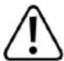
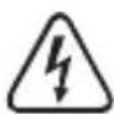
The symbol warns of hazards that can lead to personal injury.

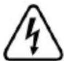
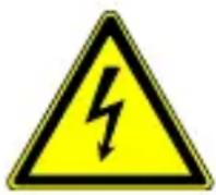
The symbol warns of dangerous voltage that can lead to personal injury by electric shock.

Protection class 2 (double or reinforced insulation, protective insulation).
Application around and removal from HAZARDOUS LIVE conductors is permitted. Personal protective equipment must be used.
CAT III
Can test and measure circuits connected to the distribution part of the building's low-voltage MAINS installation.
Alternating current (AC)

Direct current (DC)

Earth ground

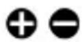
Polarity markings for direct current (DC) measurement. The symbols indicate the direction of current for taking measurements.
6 Safety instructions

Read the operating instructions carefully and especially observe the safety information. If you do not follow the safety instructions and information on proper handling, we assume no liability for any resulting personal injury or damage to property. Such cases will invalidate the warranty/guarantee.
6.1 General
The product is not a toy. Keep it out of the reach of children and pets.
Do not leave packaging material lying around carelessly. This may become dangerous playing material for children.
If you have questions which remain unanswered by this information product, contact our technical support service or other technical personnel.
- Maintenance, modifications and repairs must only be completed by a technician or an authorised repair centre.
6.2 Handling
- Handle the product carefully. Jolts, impacts or a fall even from a low height can damage the product.
6.3 Operating environment
- Do not place the product under any mechanical stress.
- Protect the appliance from extreme temperatures, strong jolts, flammable gases, steam and solvents.
- Protect the product from high humidity and moisture.
■ Protect the product from direct sunlight. - Do not switch the product on after it has been taken from a cold to a warm environment. The condensation that forms might destroy the product. Allow the product to reach room temperature before you use it.
- Never operate the product in direct proximity of strong magnetic or electromagnetic fields or transmitter aerials or HF generators. Doing so can prevent the product from functioning properly.
6.4 Operation
- Consult an expert when in doubt about the operation, safety or connection of the product.
If it is no longer possible to operate the product safely, take it out of operation and protect it from any accidental use. DO NOT attempt to repair the product yourself. Safe operation can no longer be guaranteed if the product:
– is visibly damaged,
– is no longer working properly,
– has been stored for extended periods in poor ambient conditions or
– has been subjected to any serious transport-related stresses.
6.5 Batteries
■ Correct polarity must be observed while inserting batteries.
The batteries should be removed from the device if it is not used for a long period of time to avoid damage through leaking. Leaking or damaged batteries might cause acid burns when in contact with skin, therefore use suitable protective gloves to handle corrupted batteries.
- Batteries must be kept out of reach of children. Do not leave batteries lying around, as there is risk, that children or pets swallow them.
All batteries should be replaced at the same time. Mixing old and new batteries in the device can lead to battery leakage and device damage.
- Batteries must not be dismantled, short-circuited or thrown into fire. Never recharge non-rechargeable batteries. There is a risk of explosion!
6.6 Connected devices
Also observe the safety and operating instructions of any other devices which are connected to the product.
6.7 Product
Before use, always verify measurements against a known voltage source to ensure safe operation. If abnormal or erratic operation is detected:
- Stop using immediately
– have the product inspected by a qualified technician
- When taking measurements make sure no objects are trapped between the clamp jaws (e.g., cables).
- Do not exceed the maximum permissible measurement values.
Risk of fatal electric shock! The product must never be used if the housing or battery compartment cover is open.
Risk of electric shock! Use caution when working with voltages above 30 V/AC rms (42.4 V peak), 60 V/DC.
The rotary switch should be set to the correct range / function before each use.
- Inspect the product for damage before each measurement. Never take measurements if the insulation or product is damaged.
- Use extreme caution when working around bare conductors or bus bars as contact can result in electric shock.
- When taking measurements always keep the fingers behind the finger guards.
6.8 Test leads and probes
The voltage between the connection points of the meter and the earth potential must not exceed 600 V AC/DC in CAT III.
Probe assemblies to be used for MAINS measurements should meet EN 61010-031 standard, rated CAT III 600 V, 40 A or better.
Risk of electric shock! Use caution when working with voltages above 30 V/AC rms (42.4 V peak), 60 V/DC.
Test leads must be disconnected before changing the range / function.
The cables have a wear indicator. If damaged, a second insulation layer in a different colour becomes visible. Do not use if this occurs, replace immediately!
- When taking measurements do not grip beyond the finger barrier or grip range markings on the probes.
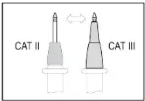
- When taking CAT III measurements, probes with cover caps (max. 4 mm free contact length) must be used to avoid accidental short circuits.
When using the probes without cover caps, measurements between the meter and the earth potential must not be performed above the measuring category CAT II.
■ Prevent short circuits by ensuring test points/connections do not touch when taking measurements.
■ Always check the probes and leads for any sign of damage before each use. Do not use if damaged, replace immediately!
7 Overview
7.1 Product
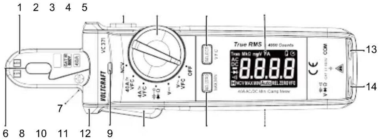
1 Current sensing clamp 2
3 Rotary switch 4
5 Display 6 Non-contact voltage (AC)
7 Work light 8 Finger guard
9 Non-contact voltage (AC) tri-colour LED
11 REL|ZERO, MAX|MIN button
13 COM terminal
HOLD button
SELECT, V.F.C button
detector tip
10 Clamp lever
12 Battery compartment
14 - + - terminal Ω
7.2 Display symbols
| Symbol | Description |
| A | Current (amps) |
| AC | Alternating current |
| DC | Direct current |
| NCV | Non-contact voltage |
| Symbol Description | |
| MAX | Maximum value |
| MIN | Minimum value |
| REL | Relative mode |
| Overload: range exceeded | |
| Automatic shut-off active | |
| TRMS | True root mean square measurement |
| Low battery indicator | |
| Display hold active | |
| ZERO | Zero position |
| Minus sign | |
| Auto | Automatic range selection is active |
| -)) | Continuity check |
| Diode test | |
| Ω | Ohm (unit of electric resistance) |
| kΩ, MΩ | Kiloohm ( 10^3 ), Megaohm ( 10^6 ) |
| V | Volt (unit of electric voltage) |
| mV | Millivolt ( 10^-3 ) |
| A | Ampere (unit of current measurement) |
| mA, μA | Milliampere ( 10^-3 ), Microampere ( 10^-6 ) |
| nF | Nanofarad ( 10^-9 ), unit of electrical capacitance |
| mF, μF | Millifarad ( 10^-3 ), Microfarad ( 10^-6 ) |
| VFC | Low-pass filter activated |
8 Replacing batteries
Important:
Low battery voltage can affect the accuracy of readings resulting in electric shock and/or injury:
- Replace the batteries when the low battery indicator shows.
- Rechargeable batteries are not recommended as they typically have a lower voltage per cell.
Risk of electric shock! Disconnect the product from any input signals before replacing the batteries.
Preconditions:
√ The power is switched OFF.
- Use a cross-head screwdriver to remove the compartment cover screw.
- Replace the batteries and match the polarity markings shown inside the compartment.
- Replace the battery compartment cover taking care not to over-tighten the screw.
9 Operation
IMPORTANT! Always observe the information contained in the section: Safety instructions [▶ 41].
9.1 Rotary switch
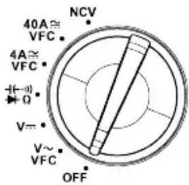
The rotary switch should be set to the correct range / function before each use.
- When a function is selected, a beep will sound and the display will update.
9.2 Power ON / OFF
The product is switched off when the function switch is in the OFF position.
■ Switch the power OFF after use.
9.3 Auto shut-off
■ Auto shut-off is active by default, it is indicated by the Symbol.
This energy saving feature will shut power off after approximately 15 minutes of no activity.
To disable auto shut-off:
- Set the rotary switch to OFF.
- Press and hold the SELECT button and then set the rotary switch to any position other than OFF.
→ The symbol will disappear and an alert will sound when disabled.
- Auto shut-off will reactivate after the power is switched OFF.
9.4 Display hold
Important:
- The display hold function freezes the display.
-
The display hold should be switched OFF before taking measurements.
-
Press the HOLD button to switch display hold ON/OFF.
The hold icon 📄ll appear when display hold is ON.
9.5 Maximum / minimum value display
In this mode the display shows the "MIN" (minimum) or "MAX" (maximum) value measured.
- Press and hold the REL/ZERO [MAX/MIN] button to enter maximum / minimum value display mode.
- Press the MAX/MIN button repeatedly to toggle between modes.
→ The display will show "MAX" or "MIN" to indicate which mode is active.
- Press and hold the MAX/MIN button to exit this mode.
9.6 Work light
■ Press and hold the HOLD button to switch the work light ON / OFF.
9.7 Relative mode
Relative mode can be used to take differential readings between two test points or for tracking changes in measurements from a defined reference point (e.g., line losses).
- Select a function using the rotary switch: V\~, V=, 4A≈, 40A≈
- Take a measurement and note the displayed value.
- Press the REL button to activate relative mode.
→ "REL" will appear on the display to indicate relative mode is active.
- Take another measurement.
→ The display will show the difference between the new reading and the initial reading.
-
Press the REL button to exit relative mode.
-
Switch the power OFF after use.
10 Measurement
! DANGER
Risk of electric shock!
Never exceed the maximum permitted input values for this product.
Use caution when circuits may contain voltages above 30 V/AC rms (42.4 V peak), 60 V/DC.

IMPORTANT! Always observe the information contained in the section:
Safety instructions [▶ 41].
10.1 Current measurement "A"
Notes:
- For best results, conductors should be centered in the clamp.
- The current sensing clamp is magnetized and a low reading may appear even when no conductor has been covered.
- Only one conductor should be covered by the current sensing clamp.
Tips:
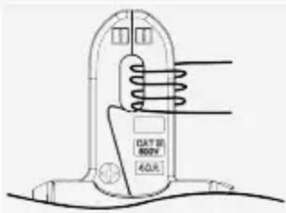
For low currents, you can increase the field strength to a measurable level:
- Wind the conductor around one side of the current clamp as shown.
- Take note of the measured current.
- Divide the measured current by the number of winds (coils).
→ The real current has been derived.
10.1.1 Alternating current (AC) measurement
Risk of electric shock! Do not use the clamp on uninsulated conductors.

■ Unclamp the conductor if (overload) appears on the display.
This product is rated for 50-60Hz. Do not exceed this frequency range as higher frequencies can dangerously overheat the magnetic circuit.
- Select a range using the rotary switch: 4A\~, 40A\~.
- (Optional step) press and hold the SELECT [V.F.C] button to switch the low-pass filter ON/OFF. The display will show "VFC" when it is active.
- Clamp the jaws around the conductor to be measured.
→ The reading will show on the display.
- Carefully remove the clamp from the conductor after taking measurements.
- Switch the power OFF after use.
Notes:
Low-pass filter "VFC":
- This software filter is only applicable to AC ranges.
- The low-pass filter suppresses noise above 400 Hz.
10.1.2 Direct current (DC) measurement
Risk of electric shock! Do not use the clamp on uninsulated conductors.

■ Unclamp the conductor if (overload) appears on the display.
Notes:
- For direct current measurements, the polarity of the clamp must match the flow of current along the conductor. A minus sign "-" will appear in front of the reading if the polarities are reversed.
- Polarity symbols + are indicated on the front and back of the jaw.
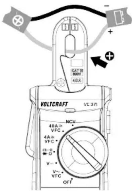
- Select a range using the rotary switch: 4A—40A.
- Press the SELECT button to enter DC mode.
→ The display will show "DC".
- Press the ZERO button to perform a zero adjustment.
→ The display will show "ZERO".
- Clamp the jaws around the conductor to be measured.
→ The reading will show on the display.
- Carefully remove the clamp from the conductor after taking measurements.
- Switch the power OFF after use.
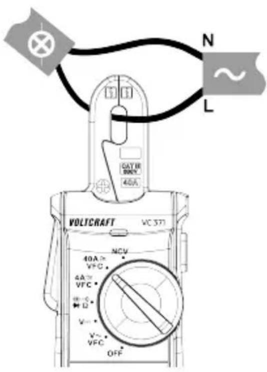
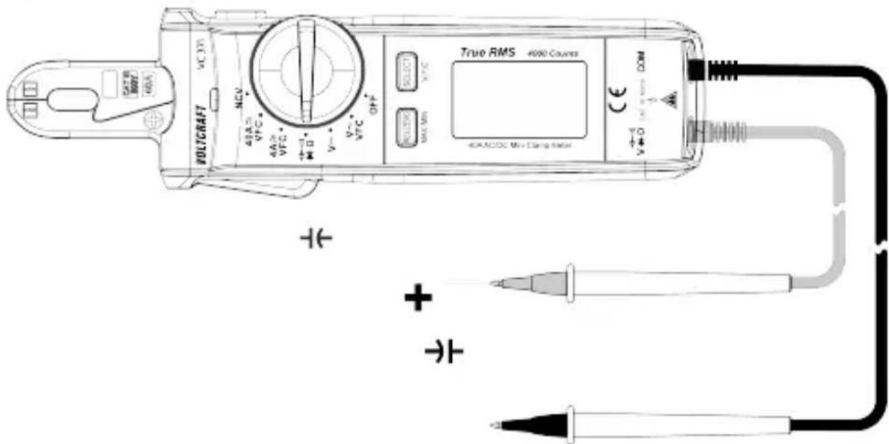
10.2 Voltage measurement "V"

WARNING: Observe all safety precautions when working on live voltages.
10.2.1 AC voltage measurement
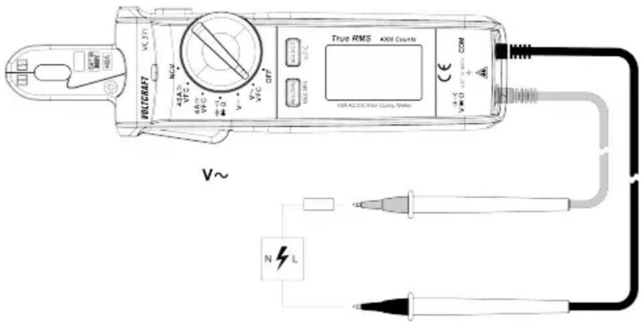
- Set the rotary switch to: V\~.
→ The display will show "AC" and "V".
- (Optional step) press and hold the SELECT [V.F.C] button to switch the low-pass filter ON/OFF. The display will show "VFC" when it is active.
- Connect the test leads to the input terminals:
- Black test lead to the negative input terminal: COM.
- Red test lead to the positive input terminal: V.
- Touch the test probe tips across the circuit or component under test. It may take a few moments for the reading to stabilize.
→ The measurement will show on the display.
The display will show icon (overload) if the measuring range is exceeded or the circuit is interrupted.
- Disconnect the test leads and switch the power OFF after use.
Notes:
Low-pass filter "VFC":
- This software filter is only applicable to AC ranges.
- The low-pass filter suppresses noise above 400 Hz.
10.2.2 DC voltage measurement
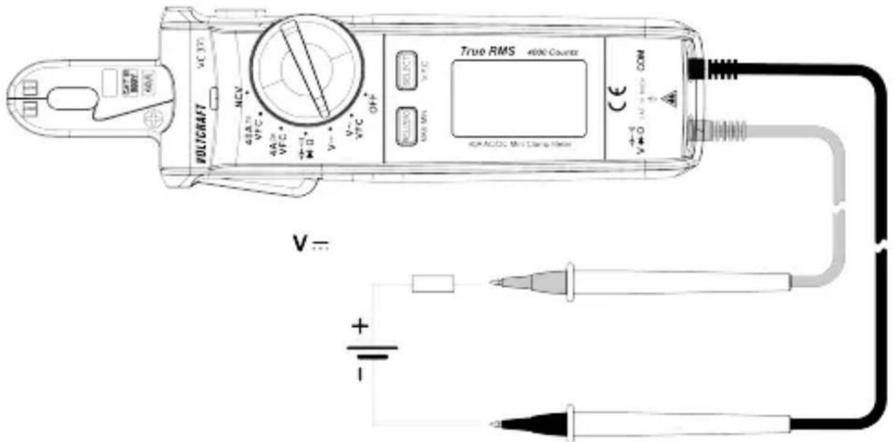
- Set the rotary switch to: V
- Press the SELECT button to enter DC mode.
→ The display will show "DC" and "mV".
- Connect the test leads to the input terminals:
- Black test lead to the negative input terminal: COM.
- Red test lead to the positive input terminal: V.
- Touch the test probe tips across the object under test (e.g., circuit, battery). It may take a few moments for the reading to stabilize.
→ The measurement will show on the display.
The display will show icon (overload) if the measuring range is exceeded or the circuit is interrupted.
→ A minus sign "-" will appear in front of the reading if the polarities are reversed.
- Disconnect the test leads and switch the power OFF after use.
10.3 Resistance measurement

WARNING: Never test on a live circuit. Remove all power from the circuit and discharge all capacitors before testing.
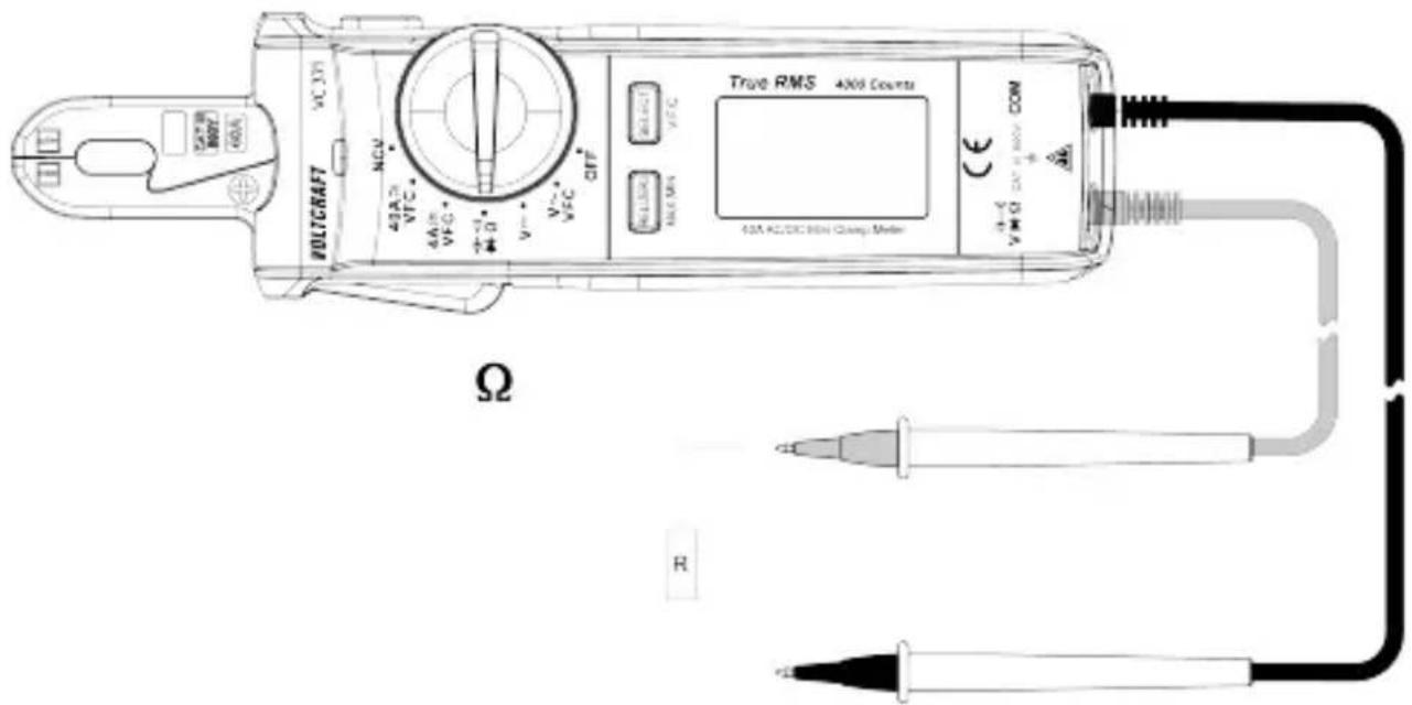
- Set the rotary switch to: Ω.
→ The display will show "k" or "M" + Ω".
- Connect the test leads to the input terminals:
- Black test lead to the negative input terminal: COM
- Red test lead to the positive input terminal: .
- Touch the test probe tips across the circuit or component under test. It may take a few moments for the reading to stabilize.
→ The measurement will show on the display.
- Disconnect the test leads and switch the power OFF after use.
Tips:
- Check the test leads for continuity by touching them together. The resistance value should be approx. 0.5 (inherent resistance of the test leads).
- For low resistance measurements (<400 ohms), you can deduct the inherent resistance of the test leads from the measurements. See section: Relative mode [▶ 49].
10.4 Capacitance measurement

WARNING: Never test on a live circuit. Remove all power from the circuit and discharge all capacitors before testing.
- Set the rotary switch to: -
-
Press the SELECT button until the display shows "n" and "F".
-
Connect the test leads to the input terminals:
-
Black test lead to the negative input terminal: COM.
-
Red test lead to the positive input terminal:
-
Touch the test probe tips across the capacitor under test. It may take a few moments for the reading to stabilize.
→ The measurement will show on the display.
→ The display will show icon (overload) if the measuring range is exceeded or the circuit is interrupted.
- Disconnect the test leads and switch the power OFF after use.
Tips:
If the capacitance being measured is ≤1 F , perform a zero adjustment to remove stray capacitance in the test leads and internal circuitry. This will improve measurement accuracy.
- Enter capacitance measurement mode.
- Press the ZERO button, the display will show "ZERO".
→ A zero adjust has been performed.
11 Testing
! DANGER
Risk of electric shock!
Never exceed the maximum permitted input values for this product.
Use caution when circuits may contain voltages above 30 V/AC rms (42.4 V peak), 60 V/DC.

IMPORTANT! Always observe the information contained in the section: Safety instructions [▶ 41].
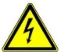
11.1 Continuity test

WARNING: Never test on a live circuit. Remove all power from the circuit and discharge all capacitors before testing.
- Set the rotary switch to: :)))
- Press the SELECT button until the display shows " -")
-
Connect the test leads to the input terminals:
-
Black test lead to the negative input terminal: COM.
-
Red test lead to the positive input terminal: -)))
-
Touch the test probe tips across the circuit or component under test.
→ A constant tone will sound if the resistance is <10 .
→ The display will show icon (overload) if the measuring range is exceeded or the circuit is interrupted.
- Disconnect the test leads and switch the power OFF after use.
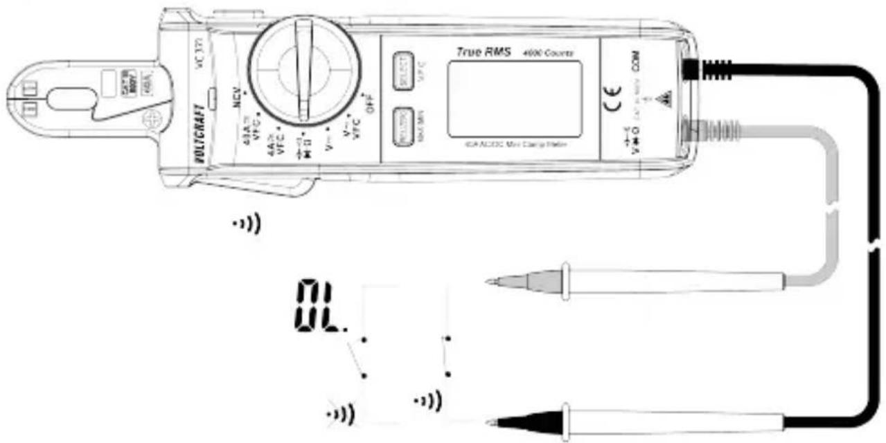
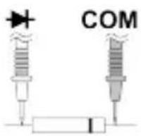
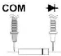
11.2 Diode test

WARNING: Never test on a live circuit. Remove all power from the circuit and discharge all capacitors before testing.
Forward test: 1. Set the rotary switch to: .
Reverse test:
- Press the SELECT button until the display shows "
-
Connect the test leads to the input terminals:
-
Black test lead to the negative input terminal: COM.
-
Red test lead to the positive input terminal:
-
Touch the test probe tips across the diode under test.
→ Forward test voltages: will show on the display as a voltage reading.
→ Reverse test voltages: will show on the display as "L".
→ A defective diode (interrupted): will show on the display as "F"
- Disconnect the test leads and switch the power OFF after use.
11.3 Non-contact voltage testing
The non-contact voltage (NCV) detection function can detect AC voltage on conductors without touching them.
Due to the high sensitivity sensor, static electricity or other sources of energy may trigger the sensor. This is normal operation.
Risk of electric shock!
Before use, always test the voltage detector on a known live circuit to ensure safe operation.
Insulation type, thickness, and distance from the voltage source may affect detection.
■ Always verify measurements using test leads before touching potentially energized circuits.
- Set the rotary switch to: NCV.
→ "NCV" and "EF" will appear on the display.
- Place the sensor tip near the conductor.
→ If AC voltage is present, the tri-colour LED will light and a beep will sound.
- If the detected voltage increases:
→ the beeping will get faster.
→ the tri-colour LED changes from green → yellow → red.
- Switch the power OFF after use.
12 Troubleshooting
| Problem Possible cause Suggested solution | ||
| 3x beeps then power OFF | Batteries are low See section:Replacing batteries [▶ 47] | |
| Display shows: "ErrE" System error Restart the product | ||
| Large idle value after performing DC zero adjustment | Remanence (residual magnetism of the measuring coil) | Briefly switch to the AC measuring function (A) |
13 Cleaning
Risk of electric shock! Disconnect the product from any input signals and switch the power OFF before cleaning.
Important:
- Do not use aggressive cleaning agents, rubbing alcohol or other chemical solutions. They damage the housing and can cause the product to malfunction.
-
Do not immerse the product in water.
-
Clean the product with a clean, lint-free, antistatic cloth. Lightly moisten if needed.
- Check to make sure the clamp mating surface is clean. Trapped dirt or debris can result in measurement errors.
14 Disposal
14.1 Product
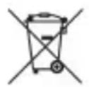
This symbol must appear on any electrical and electronic equipment placed on the EU market. This symbol indicates that this device should not be disposed of as unsorted municipal waste at the end of its service life.
Owners of WEEE (Waste from Electrical and Electronic Equipment) shall dispose of it separately from unsorted municipal waste. Spent batteries and accumulators, which are not enclosed by the WEEE, as well as lamps that can be removed from the WEEE in a non-destructive manner, must be removed by end users from the WEEE in a non-destructive manner before it is handed over to a collection point.
Distributors of electrical and electronic equipment are legally obliged to provide free take-back of waste. Conrad provides the following return options free of charge (more details on our website):
in our Conrad offices
■ at the Conrad collection points
at the collection points of public waste management authorities or the collection points set up by manufacturers or distributors within the meaning of the ElektroG
End users are responsible for deleting personal data from the WEEE to be disposed of.
It should be noted that different obligations about the return or recycling of WEEE may apply in countries outside of Germany.
14.2 (Rechargeable) batteries
Remove batteries/rechargeable batteries, if any, and dispose of them separately from the product. According to the Battery Directive, end users are legally obliged to return all spent batteries/rechargeable batteries; they must not be disposed of in the normal household waste.
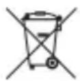
Batteries/rechargeable batteries containing hazardous substances are labelled with this symbol to indicate that disposal in household waste is forbidden. The abbreviations for heavy metals in batteries are:
Cd = Cadmium, Hg = Mercury, Pb = Lead (name on (rechargeable) batteries, e.g. below the trash icon on the left).
Used (rechargeable) batteries can be returned to collection points in your municipality, our stores or wherever (rechargeable) batteries are sold. You thus fulfil your statutory obligations and contribute to environmental protection.
Batteries/rechargeable batteries that are disposed of should be protected against short circuit and their exposed terminals should be covered completely with insulating tape before disposal. Even empty batteries/rechargeable batteries can contain residual energy that may cause them to swell, burst, catch fire or explode in the event of a short circuit.
15 Technical data
15.1 General
Power supply...... 2x AAA 1.5 V batteries
Measuring categories .... CAT III 600 V
Current measurement...... max. 40 A (AC/DC)
Display.... 4000 counts (2 - 3 renewals/sec.)
Clamp opening range .... width: max. 5.5 mm, height: max. 13 mm
Automatic shut-off...... approx. 15 mins
Display type...... EBTN
Operating altitude .... max. 2000 m (above sea level)
Operating conditions.... 0 to +28 °C, ≤95 % RH (non-condensing)
+28 to +40 °C, ≤75 % RH (non-condensing)
+40 to +50 °C, ≤45 % RH (non-condensing)
Storage conditions.... -10 to +50 °C, ≤80 % RH (non-condensing)
Dimensions (W x H x D) ...... 188 x 51 x 36 mm
Weight .... approx. 173 g
15.2 Test leads and probes
Rated voltage .... CAT III 1000 V
Rated current.... 10 A
Protection class ...... II
15.3 Specifications
15.3.1 Accuracy
- Specified accuracy ± (% of the reading + display error in counts).
Accuracy is maintained for 1 year at +23 °C (± 5 °C), ≤75 % RH (non-condensing).
Temperature coefficient: +0.1 x (specified accuracy) / 1 °C.
To avoid impaired measurements, do not operate the product in areas with electromagnetic field strengths >1 V/m (±5 %).
15.3.2 Calibration
The recommended calibration interval is 1 year.
- Calibration should only be performed by qualified personnel.
15.3.3 Alternating current (AC)
| Range Resolution Accuracy* | |
| 4.000 A 0.001 A ±(4.0 % +10) | with a low-pass filter (VFC) ±(6.0 % + 20) |
| 40.00 A 0.01 A ±(4.0 % +9) | with a low-pass filter (VFC) ±(6.0 % + 20) |
| *Accuracy: 5 - 100 % of the measuring rangeOverload protection: 600 V 40 AFrequency range: 50-60 HzPermitted display with unused measuring input: ≤5 counts (clamp closed) | |
| True RMS Crest factor (CF) for non-sinusoidal signals: max. 3.0:Crest factor 1.0 – 2.0 : +4 % deviationCrest factor 2.0 – 2.5 : +5 % deviationCrest factor 2.5 – 3.0 : +7 % deviation | |
15.3.4 Direct current (DC)
| Range Resolution Accuracy* | |
| 4.000 A 0.001 A ±(3.5 % +9) | |
| 40.00 A 0.01 A ±(3.5 % +5) | |
| *Accuracy: 5 - 100 % of the measuring range; after successful zero adjustmentOverload protection: 600 V, 40 A | |
15.3.5 AC voltage
| Range Resolution Accuracy* | |
| 4.000 V 0.001 V ±(1.2 % +5) | |
| 40.00 V 0.01 V ±(1.5 % +5) | |
| 400.0 V 0.1 V ±(1.5 % +5) | with a low-pass filter (VFC) ±(4.0 % + 10) |
| 600 V 1 V ±(2.0 % +5) | with a low-pass filter (VFC) ±(4.0 % + 10) |
| *Accuracy: 5 - 100 % of the measuring rangeOverload protection: 600 VFrequency range: 45-400 HzImpedance: ≥10 MΩPermitted display with unused measuring input: ≤5 counts (clamp closed) | |
| True RMS Crest factor (CF) for non-sinusoidal signals: max. 3.0:Crest factor 1.0 – 2.0 : +4 % deviationCrest factor 2.0 – 2.5 : +5 % deviationCrest factor 2.5 – 3.0 : +7 % deviation | |
15.3.6 DC voltage
| Range Resolution Accuracy* | |
| 400.0 mV 0.1 mV ±(0.8 % +8) | |
| 4.000 V 0.001 V ±(1.2 % +5) | |
| 40.00 V 0.01 V ±(1.2 % +5) | |
| 400.0 V 0.1 V ±(1.2 % +5) | |
| 600 V 1 V ±(1.5 % +5) | |
| *Accuracy: 5 - 100 % of the measuring rangeOverload protection: 600 VImpedance:≥10 MΩPermitted display with unused measuring input: ≤5 counts (clamp closed) | |
15.3.7 Resistance
| Range Resolution Accuracy* | ||
| 400.0 Ω 0.1 Ω ±(1.2 % +5) | ||
| 4.000 kΩ 0.001 kΩ | ±(1.0 % +5) | |
| 40.00 kΩ 0.01 kΩ | ±(1.2 % +5) | |
| 400.0 kΩ 0.1 kΩ | ±(1.2 % +5) | |
| 4.000 MΩ 0.001 MΩ | ±(1.2 % +5) | |
| 40.00 MΩ 0.01 MΩ | ±(2.0 % +5) | |
| *Accuracy: 5 - 100 % of the measuring range, <400 Ω after successful zero adjustmentOverload protection: 600 VMeasuring voltage: approx. 0.5 V | ||
15.3.8 Capacitance
| Range Resolution Accuracy* | |
| 4.000 nF 0.001 nF ±(4.0 % +10) | |
| 40.00 nF 0.01 nF ±(4.0 % +5) | |
| 400.0 nF 0.1 nF ±(3.0 % +5) | |
| 4.000 μF 0.001 μF ±(3.0 % +5) | |
| 40.00 μF 0.01 μF ±(3.0 % +5) | |
| 100.0 μF 0.1 μF ±(5.0 % +10) | |
| *Accuracy: 10 - 100 % of the measuring range, ≤1 μF after successful zero adjustmentOverload protection: 600 VMeasuring voltage: approx. 0.5 VPermitted display with unused measuring input: ≤5 counts (clamp closed) | |
15.3.9 Diode test
| Test voltage Resolution | |
| Approx. 3.2 V 0.001 V | |
| Overload protection: 600 VTest current: ≤1.7 mA | |
15.3.10 Acoustic continuity text
| Test voltage Resolution | |
| Approx. 1 V 0.1 Ω | |
| Overload protection: 600 VMeasuring range: max. 400 ΩTest current: <0.4 mA | |
15.3.11 Non-contact (AC) voltage test
| Test voltage Distance | |
| ≥100 V/AC max. 5 mm | |
| ■ Frequency: 50-60 Hz | |

Sommaire
France technique@conrad-
(email): france.fr
Courant continu (CC)

Mise à la terre
1 Stroommeetang 2
3 Draaiknop 4
HOLD-knop
SELECT, V.F.C-knop
5 Display 6 Contactloze spanningsdetectortip
(AC)
10.1 Stroommeting "A"
Opmerkingen:
Doorlaatme- ting:
Terugmeting:
Copyright by Conrad Electronic SE
*2893199_V3_1223_dh_mh_de 18014399538909707-1 I3/O3 en

This is a publication by Conrad Electronic SE, Klaus-Conrad-Str. 1, D-92240 Hirschau (www.conrad.com).
All rights including translation reserved. Reproduction by any method (e.g. photocopying, microfilming or the capture in electronic data processing systems) requires prior written approval from the editor. Reprinting, also in part, is prohibited. This publication reflects the technical status at the time of printing.
Copyright by Conrad Electronic SE
*2893199_V3_1223_dh_mh_en 18014399538909707-2 I3/O3 en

Copyright by Conrad Electronic SE
*2893199_V3_1223_dh_mh_fr 18014399538909707-3 l3/O3 en

Copyright by Conrad Electronic SE
*2893199_V3_1223_dh_mh_nl 18014399538909707-4 I3/O3 en
- Introduction
- Intended use
- Delivery contents
- Operating Instructions for download
- Description of symbols
- Safety instructions
- General
- Handling
- Operating environment
- Operation
- Batteries
- Connected devices
- Product
- Test leads and probes
- Overview
- Product
- Display symbols
- Replacing batteries
- Important:
- Preconditions:
- Operation
- Rotary switch
- Power ON / OFF
- Auto shut-off
- Display hold
- Maximum / minimum value display
- Work light
- Relative mode
- Measurement
- ! DANGER
- Current measurement "A"
- Notes:
- Tips:
- Alternating current (AC) measurement
- Direct current (DC) measurement
- Voltage measurement "V"
- AC voltage measurement
- DC voltage measurement
- Resistance measurement
- Capacitance measurement
- Testing
- Risk of electric shock!
- Continuity test
- Diode test
- Non-contact voltage testing
- Troubleshooting
- Cleaning
- Disposal
- Product
- (Rechargeable) batteries
- Technical data
- General
- Test leads and probes
- Specifications
- Accuracy
- Calibration
- Alternating current (AC)
- Direct current (DC)
- AC voltage
- DC voltage
- Resistance
- Capacitance
- Diode test
- Acoustic continuity text
- Non-contact (AC) voltage test
- Sommaire
- Stroommeting "A"
- Opmerkingen:
Brand : VOLTCRAFT
Model : VC371
Category : Multimeter