BBN3306SSC - Basket BROAN - Free user manual and instructions
Find the device manual for free BBN3306SSC BROAN in PDF.

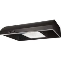
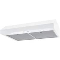
| Product Type | Built-in range hood |
| Brand | Broan |
| Model | BBN3306SSC |
| Use | Indoor residential use only |
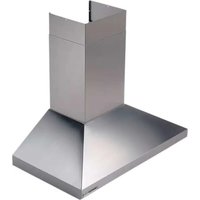
| Installation position | Under cabinet, vertical or horizontal venting |
| Cutout dimensions (cabinet opening) | 10 1/4 in x 28 1/16 in |
| Recommended height above cooking surface | 24 to 30 in |
| Material | Stainless steel |
| Electrical supply | 120 V, 60 Hz, grounded |
| Maximum airflow | 600 CFM (adjustable to 400 or 300 CFM via Code Ready Technology) |
| Fan speeds | 4 speeds (low, medium-low, medium-high, high) |
| Lighting | Integrated LED, dimmable (low/high) |
| Control | Touch controls |
| Special features | Heat Sentry™ (thermostat), delay shutoff (10 min), filter maintenance reminder |
| Grease filters | 2 dishwasher-safe metal filters |
| Recirculation filters | Optional (HARKBN30 kit), replace every 3 to 6 months |
| Recommended duct type | Metal, 6 in or 8 in round, or 3 1/4 in x 10 in rectangular |
| Warranty | 1 year parts and labor (3 years for LED modules) |
| Weight | Approximately 15 kg (estimated) |
| Code Ready Technology | Allows reducing maximum airflow to 400 or 300 CFM to comply with MUA codes |
| Controls | Fan, light, delay shutoff |
Frequently Asked Questions - BBN3306SSC BROAN
User questions about BBN3306SSC BROAN
0 question about this device. Answer the ones you know or ask your own.
Ask a new question about this device
Download the instructions for your Basket in PDF format for free! Find your manual BBN3306SSC - BROAN and take your electronic device back in hand. On this page are published all the documents necessary for the use of your device. BBN3306SSC by BROAN.
USER MANUAL BBN3306SSC BROAN
BBN3306SS, BBN3306SSC
INSTALLATION,
USE & CARE INSTRUCTIONS
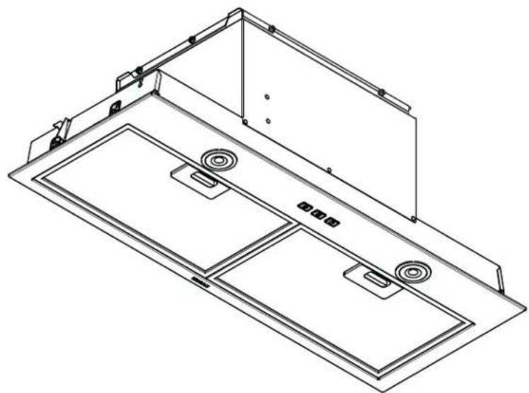
natural_image
Technical line drawing of a multi-panel electronic device casing with mounting brackets and internal compartments (no text or symbols)Safety 3-4
Installation....5-15
Recommended Tools and Accessories....5
Contents. 5
Install Ductwork (Ducted Installations Only) 5
Remove the Adapter/Damper....6
Remove the Cabinet Brackets 6
Prepare the Cabinet 7-9
Prepare the Unit 10-11
Install the Unit....12-14
Connect Ductwork....14
Wiring....15
Install the Filters 15
Operation 16-17
Soft-Touch Control 16
Heat Sentry™ 16
Code Ready™ Technology Activation 17
Maintenance and Cleaning ....18
Grease Filters 18
Non-Ducted Recirculation Filters 18
Stainless Steel Cleaning. 18
Wiring Diagram 19
Service Parts....20
Warranty 21
To register your product, please visit our website:
In the United States - broan-nutone.com
In Canada - broan-nutone.ca
For Technical Support, call:
In the United States - 800-558-1711
In Canada - 800-567-3855
Installer: Leave this manual with the homeowner.
READ AND SAVE THESE INSTRUCTIONS
Intended for domestic cooking only
WARNING

TO REDUCE THE RISK OF FIRE, ELECTRIC SHOCK, OR INJURY TO PERSONS, OBSERVE THE FOLLOWING:

- Use this unit only in the manner intended by the manufacturer. If you have questions, contact the manufacturer at the address or telephone number listed in the warranty.
- Before servicing or cleaning unit, switch power off at service panel and lock the service disconnecting means to prevent power from being switched on accidentally. When the service disconnecting means cannot be locked, securely fasten a prominent warning device, such as a tag, to the service panel.
- Installation work and electrical wiring must be done by a qualified person(s) in accordance with all applicable codes and standards, including fire-rated construction codes and standards.
- Sufficient air is needed for proper combustion and exhausting of gases through the flue (chimney) of fuel burning equipment to prevent backdrafting. Follow the heating equipment manufacturer's guideline and safety standards such as those published by the National Fire Protection Association (NFPA), and the American Society for Heating, Refrigeration and Air Conditioning Engineers (ASHRAE), and the local code authorities.
- When cutting or drilling into wall or ceiling, do not damage electrical wiring and other hidden utilities.
- Ducted fans must always be vented to the outdoors.
- Do not use this unit with any separate solid-state speed control device.
• To reduce the risk of fire, use only metal ductwork.
• This unit must be grounded.
- When installing, servicing or cleaning the unit, it is recommended to wear safety glasses and gloves.
- When applicable local regulations comprise more restrictive installation and/or certification requirements, the aforementioned requirements prevail on those of this document and the installer agrees to conform to these at his own expense.
WARNING

TO REDUCE THE RISK OF A RANGE TOP GREASE FIRE:
A. Never leave surface units unattended at high settings. Boilovers cause smoking and greasy spillovers that may ignite. Heat oils slowly on low or medium settings.
B. Always turn hood ON when cooking at high heat or when flambeing food (i.e. Crepes Suzette, Cherries Jubilee, Peppercorn Beef Flambé).
C. Clean ventilating fans frequently. Grease should not be allowed to accumulate on fan or filter.
D. Use proper pan size. Always use cookware appropriate for the size of the surface element.
TO REDUCE THE RISK OF INJURY TO PERSONS IN THE EVENT OF A RANGE TOP GREASE FIRE, OBSERVE THE FOLLOWING:\*
- SMOTHER FLAMES with a close-fitting lid, cookie sheet, or metal tray, then turn off the burner. BE CAREFUL TO PREVENT BURNS. If the flames do not go out immediately, EVACUATE AND CALL THE FIRE DEPARTMENT.
- NEVER PICK UP A FLAMING PAN - You may be burned.
- DO NOT USE WATER, including wet dishcloths or towels - violent steam explosion will result.
- Use an extinguisher ONLY if:
A. You know you have a Class ABC extinguisher and you already know how to operate it.
B. The fire is small and contained in the area where it started.
C. The fire department is being called.
D. You can fight the fire with your back to an exit.
* Based on "Kitchen Fire Safety Tips" published by NFPA.
CAUTION

- For indoor residential use only.
- To reduce risk of fire and to properly exhaust air, be sure to duct air outside. Do not vent exhaust air into spaces within walls or ceilings or into attics, crawl spaces, or garages.
• Take care when using cleaning agents or detergents. - Avoid using food products that produce flames under the Range Hood.
- For general ventilating use only. Do not use to exhaust hazardous or explosive materials and vapors.
- To avoid motor bearing damage and noisy and/or unbalanced impellers, keep drywall spray, construction dust, etc. off power unit.
- Your hood motor has a thermal overload which will automatically shut off the motor if it becomes overheated. The motor will restart when it cools down. If the motor continues to shut off and restart, have the hood serviced.
- The bottom of the hood MUST NOT BE LESS than 24" and recommended at a maximum of 30" above the cooktop for best capture of cooking impurities.
- Use only with range hood cord connection kits that have been investigated and found acceptable for use with this model range hood.
- Please read specification label on product for further information and requirements.
For ADA compliance installation guidelines, please type the model number into our website.
RECOMMENDED TOOLS AND ACCESSORIES
- Measuring tape
• Phillips screwdriver no. 2 - Nut driver or socket 3/8"
- Flat blade screwdriver (to open knockout holes)
- Saw (to cut holes in cabinet)
- Sheet metal shears
- Pliers
• Metal foil duct tape
• Scissors (to cut metal foil duct tape)
- Pencil
- Wire stripper
• 2 Appropriate wire nuts
- Strain relief, 7/8" diameter (to secure house wiring cable to the hood)
- Filler kit HADTBN30 (for 30") (optional)
CONTENTS
Before proceeding to the installation, check the contents of the box. If items are missing or damaged, contact the manufacturer.
Make sure that the following items are included:
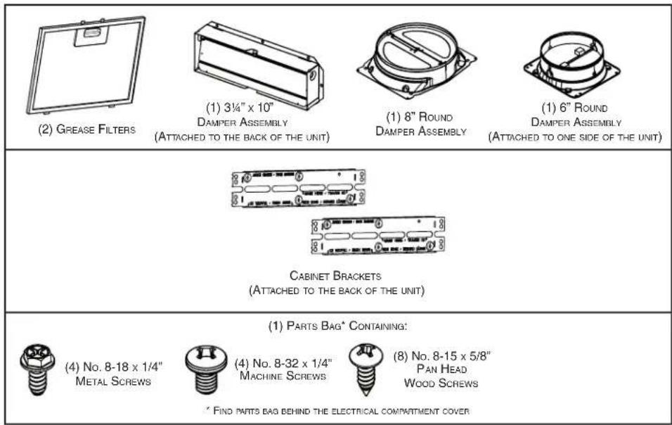
text_image
(2) GREASE FILTERS (1) 3¼" x 10" DAMPER ASSEMBLY (ATTACHED TO THE BACK OF THE UNIT) (1) 8" ROUND DAMPER ASSEMBLY (1) 6" ROUND DAMPER ASSEMBLY (ATTACHED TO ONE SIDE OF THE UNIT) CABINET BRACKETS (ATTACHED TO THE BACK OF THE UNIT) (1) PARTS BAG* CONTAINING: (4) No. 8-18 x 1/4" METAL SCREWS (4) No. 8-32 x 1/4" MACHINE SCREWS (8) No. 8-15 x 5/8" PAN HEAD WOOD SCREWS * FIND PARTS BAG BEHIND THE ELECTRICAL COMPARTMENT COVERINSTALL THE DUCTWORK (DUCTED INSTALLATION ONLY)
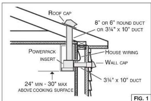
NOTE: To reduce the risk of fire, use only metal ductwork.
- Decide where the ductwork will run between the insert and the outside. (FIG. 1)
- A straight, short duct run will allow the hood to perform most efficiently.
- Long duct runs, elbows, and transitions will reduce the performance of the hood. Use as few of them as possible. Larger ducting may be required for best performance with longer duct runs.
- Install wall cap or roof cap (sold separately). Connect metal ductwork to cap and work back towards the hood location. Use 2" metal foil duct tape to seal the joints between ductwork sections.
text_image
ROOF CAP 8" OR 6" ROUND DUCT OR 3¼" x 10" DUCT POWERPACK INSERT HOUSE WIRING WALL CAP 3¼" x 10" DUCT 24" MIN - 30" MAX ABOVE COOKING SURFACE FIG. 1REMOVE THE ADAPTER/DAMPER AND 6-IN. ROUND DAMPER
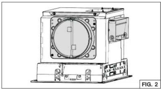
Detach and set aside the 3¼" x 10" adapter/damper and the 6-in.-round damper (grey parts in FIG. 2) from back and side of the powerpack insert by removing their 2 retaining screws. Discard the screws.
natural_image
Technical line drawing of a mechanical device with mounting base and central circular component (no text or symbols)REMOVE THE CABINET BRACKETS
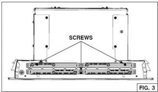
Detach the cabinet brackets (grey part in FIG. 3) from the back of the powerpack insert by removing its 3 retaining screws. Discard the screws.
text_image
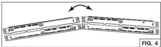
SCREWS FIG. 3Fold up and down the bracket until it is split in two separate parts (FIG. 4). Keep the brackets for possible further use.
text_image
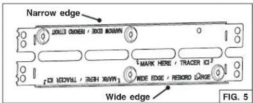
FIG. 4NOTE: Both cabinet brackets have one wide edge and one narrow edge (FIG. 5), to cover all installation configurations depending on cabinet widths.
text_image
Narrow edge MARK HERE / TRACER ICI MARK HERE / TRACER ICI WIDE EDGE / RECORD LARGE Wide edge FIG. 5PREPARE THE CABINET
WARNING
The cabinet must be secured to wall studs or other wooden framework behind the drywall to support the weight of this unit. Failure to do so may cause personal injury or damage to countertop or cooktop.
NOTES: A. The unit has to be installed inside the cabinet.
B. The unit should be mounted centered laterally over the cooktop burners.
C. For back to front position, the unit must be mounted according to local building codes.
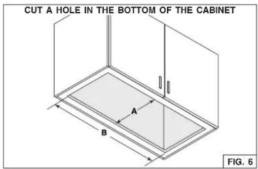
- Cut a hole in the bottom of the cabinet, using the dimensions shown (FIG. 6).
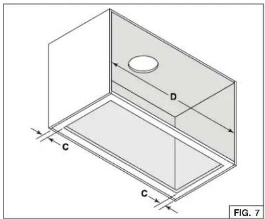
- Measure the remaining material of the cabinet bottom sides (C), (FIG. 7) if it is 1/4" or more, there is no need to use the cabinet brackets. Go to step 7 on page 9.
- When there is less than 1/4" remaining material (C), carefully remove those strips. Measure the cabinet inner width (D) (FIG. 7). Refer to the table below to see which cabinet bracket edge configuration must be used.
| NARROW EDGE | WIDE EDGE |
| DFrom 28-1/16" to < 28-1/2" | DFrom 28-1/2" to 29" |
- Pay attention to the Ease of Install hooks location on the unit (distance given from unit front flange, FIG. 8). Measure and mark the position of the Ease of Install hooks (shown as E in FIG. 9 on next page) on both cabinet side walls.
text_image
CUT A HOLE IN THE BOTTOM OF THE CABINET A B FIG. 6A = 10 ^1/4 B = 28 ^1/16
text_image
C D C FIG. 7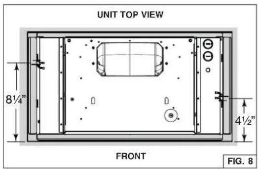
text_image
UNIT TOP VIEW 8½" 4½" FRONT FIG. 8PREPARE THE CABINET (CONT'D)
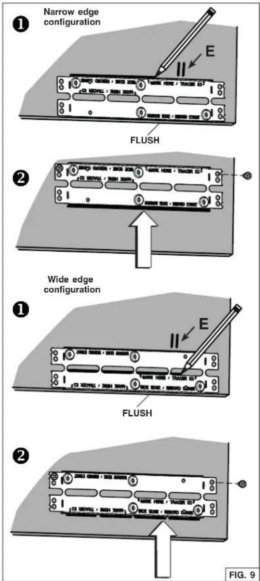
- Install the cabinet brackets as follow (FIG. 9):
① Align the bracket flush with the bottom of the right cabinet side panel, with the hooks marked position (E) between the bottom embossed holes. For the narrow edge configuration, trace a line on the top of the bracket. For wide edge configuration, trace a line at the bottom of the central slots.
② Lift the bracket flush with the marked lined. Assemble the bracket to the cabinet side panel using 2 no. 8 x 5/8" wood screws (included in parts bag) through the upper holes.
NOTE: Do not use the embossed holes to attach the bracket to the cabinet.
③ Repeat steps ① to ② for the left cabinet side panel.
PREPARE THE CABINET (CONT'D)
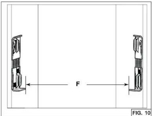
- Measure the distance between both bottom bracket edges (F) (FIG. 10). The table below shows the appropriate distance needed.
| NARROW EDGE | WIDE EDGE |
| FFrom 27-7/8" to < 28-1/16" | FFrom 28-1/16" to 28-5/16" |
If the measured distance needs to be shortened, screw two no. 8-32 x 1/4" machine screws, in each bottom embossed cabinet brackets hole; this will slightly bend the bottom part of the brackets (FIG. 11). Screw both brackets until the appropriate distance is obtained.
- Optional
There are 7 different sizes of fillers (sold separately) designed to fit up to 15-in. depth cabinets (order HADTBN30). Choose the filler that fits better to cover the back bottom edge of the cabinet. Use 4 no. 6 x 1/2" truss head wood screws (included in the optional kit) to mount it (FIG. 12).
CAUTION
Never use an electric screwdriver or drill to screw the filler to the bottom edge of cabinet; use a standard screwdriver.
HORIZONTAL EXHAUST INSTALLATION ONLY
This powerpack insert is factory shipped to exhaust vertically; however, it is possible to make it exhaust horizontally (3¼" x 10" ducting only).
- Cut the hole for the horizontal exhaust through the back wall of the cabinet using the dimensions shown. (FIG. 13).
text_image
F FIG. 10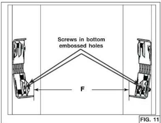
text_image
Screws in bottom embossed holes F FIG. 11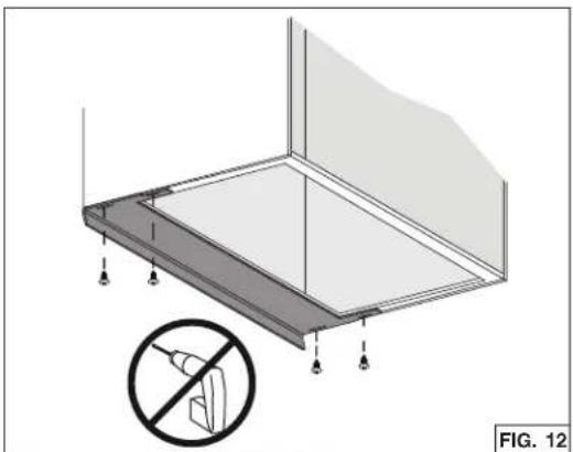
natural_image
Architectural diagram of a roof structure with no visible text or symbols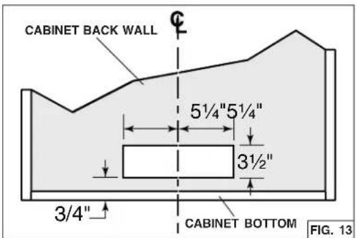
text_image
CABINET BACK WALL 5½"5½" 3½" 3/4" CABINET BOTTOM FIG. 13PREPARE THE UNIT
ALL INSTALLATIONS
- If present, remove all protective polyfilm from the unit and/or parts.
-
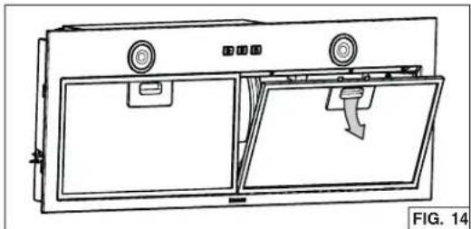
Remove the grease filters by pushing down on latch tab and tilting the filters downward (FIG. 14). Set aside the filters.
-
Disassemble the electrical compartment cover (grey part in FIG. 15) from inside the unit by removing its retaining screw. Remove the parts bag behind the cover. Set aside the parts bag and the cover along with its screw.
-
Punch out one of the two knock-out holes. Install an appropriate 7/8" diameter strain relief (not included, grey part in FIG. 16).
NOTE: The HCK44 cord connection kit (optional) can be used instead of the house power cable. Refer to the instruction packed with the HCK44 cord connection kit.
HORIZONTAL EXHAUST INSTALLATION ONLY
-
Remove and discard the screw circled in FIG. 17. NOTE: This screw might be present or not.
-
Unplug the blower cable from its connector on faceplate. Disassemble the faceplate from the unit by removing its 4 retaining screws (two per side, circled in FIG. 18). Set aside the faceplate along with its screws.
natural_image
Technical line drawing of a door frame with doors, doors, and a handle (no text or symbols)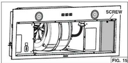
text_image
SCREW FIG. 15
natural_image
Technical line drawing of a mechanical housing component with an inset close-up view (no text or symbols)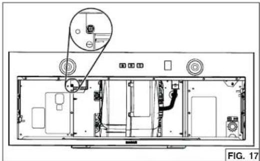
natural_image
Technical line drawing of a device rear panel with internal components and a magnified inset showing a component detail (no text or symbols present)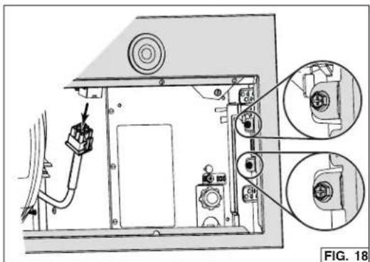
natural_image
Technical diagram of an electronic device showing internal components and wiring (no text or symbols)PREPARE THE UNIT (CONT'D)
HORIZONTAL EXHAUST INSTALLATION ONLY (CONT'D)
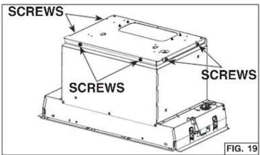
- Remove the 6 screws (2 per side and 2 in front) retaining the blower support plate to the top of the unit (FIG. 19). Carefully lift out and set aside the blower with its support plate. The blower will be reinstalled later in the unit.
- From inside the unit, detach the back plate (grey part in FIG. 20) by removing its both retaining nuts using 3/8" diameter socket. Set aside the nuts and plate.
- Install the back plate on top of the unit, where the blower support plate was. Orient the holes nearby the corners towards the back of the unit. Assemble to the top of the unit using 6 screws previously removed in step 7 (FIG. 21).
VERTICAL EXHAUST INSTALLATION ONLY
- For rectangular ducting, use 2 included no. 8-18 x 1/4" metal screws to attach the included 3¼" x 10" adapter damper on top of the unit, over the blower exhaust opening (FIG. 22).
NOTE: The damper hinge must be towards the front of the unit.
For round ducting, use 4 included no. 8-18 x 1/4" metal screws to attach the included 6-in. round (or 8-in. round) adapter damper on top of the unit, over the blower exhaust opening (FIG. 22).
NOTE: The damper hinge must be parallel to the sides of the unit.
text_image
SCREWS SCREWS SCREWS FIG. 19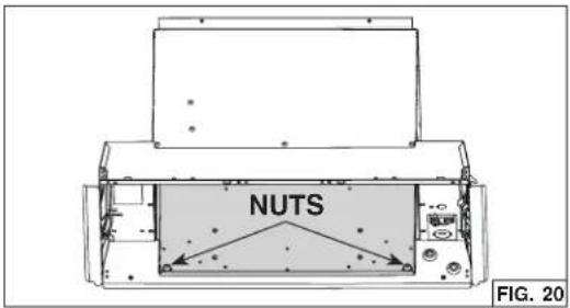
text_image
NUTS FIG. 20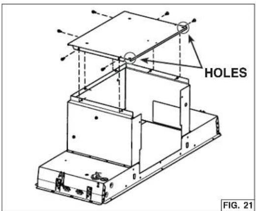
text_image
HOLES FIG. 21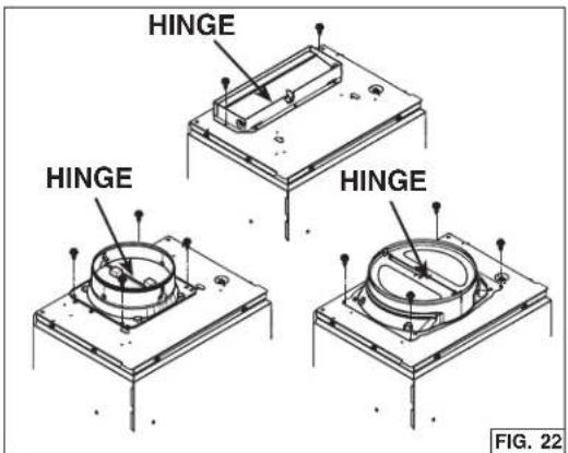
text_image
HINGE HINGE HINGE FIG. 22INSTALL THE UNIT
- Run house power cable between service panel and unit location. Stub out a 2-foot length of power cable inside the cabinet. Insert the power cable in the unit through the 7/8" diameter strain relief previously installed.
NOTE: Not necessary if the optional HCK44 cord connection kit is used.
- Insert the unit in the cabinet, until you feel a 'click' from both sides of the unit, confirming that the Ease of Install hooks rest on the top of the cabinet bottom sides ①, or cabinet brackets ② or ③ (FIG. 23). Move the unit from left to right, from rear to front and up to ensure the Ease of Install hooks are retaining the unit inside the cabinet.
NOTE: The unit will be protruding below the cabinetry until tightened.
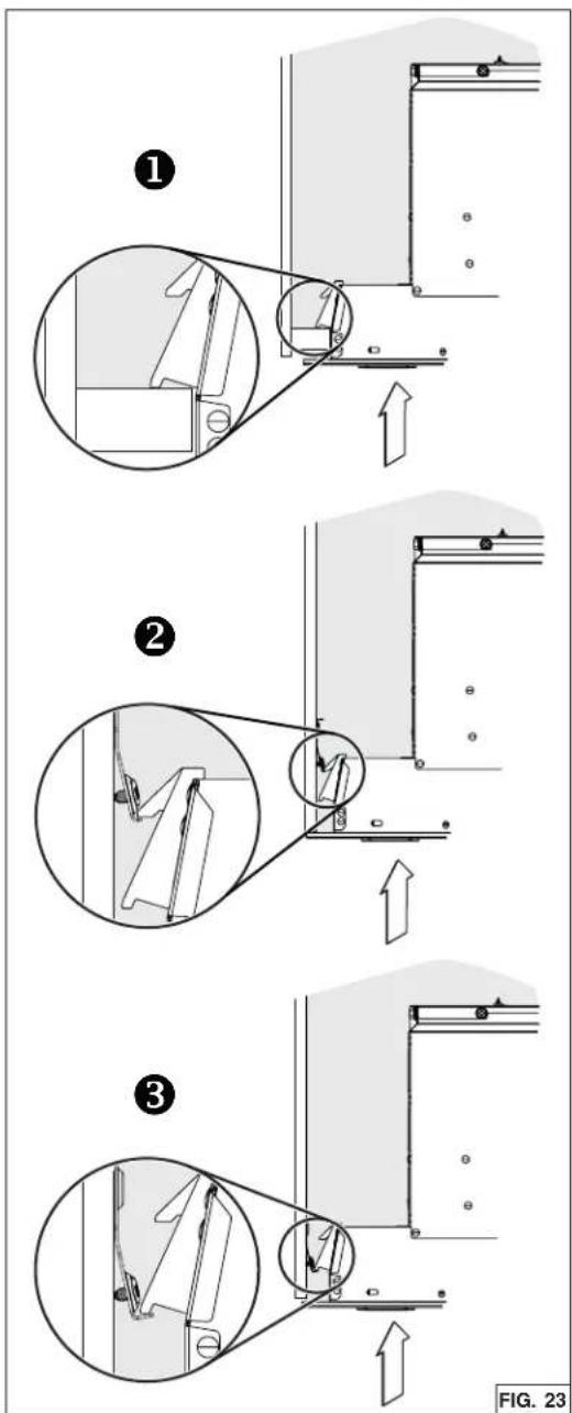
text_image
Technical diagram illustrating three-step assembly steps of a mechanical device, labeled ① to ③ with directional arrows and magnified views.NOTE: If, for any reason, the unit has to be removed from the cabinet, it is possible to disengage the Ease of Install hooks. To do so, while holding and pushing on one side of the unit, lift simultaneously Ease of Install hooks levers (1 and 2, grey parts in FIG. 24) in the other side of the unit until the hooks are retracted.
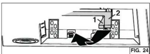
text_image
1 2 FIG. 24INSTALL THE UNIT (CONT'D)
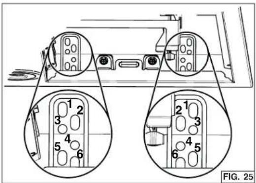
- Lift the unit until contact is made between the unit flange and cabinet. Secure the unit to the cabinet using 4 no. 8 x 5/8" wood screws included in parts bag (2 screws per side). Use upper or lower holes (1, 2, 3, 4, 5 or 6) (FIG. 25).
WARNING
The Ease of Install hooks TEMPORARILY hold the unit in place. The unit MUST BE secured to the cabinet using the included 4 screws.
WARNING
Never use this unit as a shelf.
HORIZONTAL EXHAUST INSTALLATION ONLY
-
From inside the unit, slide the 3¼" x 10" adapter/damper in the horizontal duct, then attach it to the unit using aluminum duct tape all around the joint (FIG. 26). Ensure the damper opens as shown in damper side view.
-
Insert the blower with its support plate inside the unit, where the back plate was initially (A). Attach to the unit using 2 nuts previously removed in step 8 on page 11 (B) (FIG. 27).
text_image
FIG. 25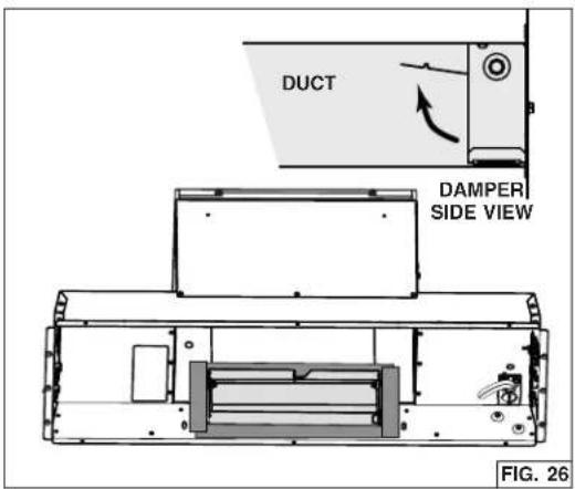
text_image
DUCT DAMPER SIDE VIEW FIG. 26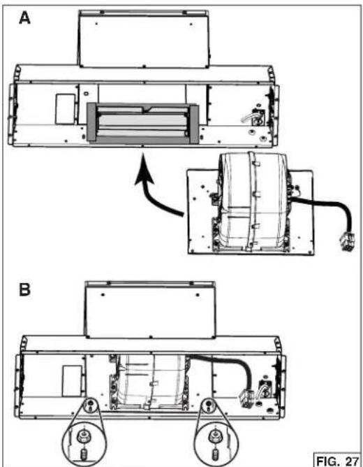
text_image
A B FIG. 27INSTALL THE UNIT (CONT'D)
HORIZONTAL EXHAUST INSTALLATION ONLY (CONT'D)
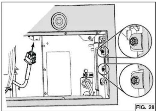
- Reinstall and secure the faceplate to the unit using its 4 retaining screws (two per side, circled in FIG. 28). Plug the blower cable to its connector on faceplate (FIG. 28).
natural_image
Technical line drawing of an electronic device with labeled components and a magnified inset showing internal wiring (no text or symbols present)CONNECT DUCTWORK
VERTICAL EXHAUST INSTALLATION ONLY
Ducted Installation
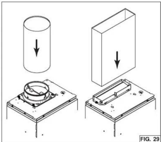
Use 6-in. round, 8-in. round or 3¼" x 10" metal duct to connect the adapter damper on the top of the unit to the ductwork above (FIG. 29, 8-in. round not shown). Seal the joint using aluminum duct tape.
Non-Ducted Installation
The HARKBN30 non-duct kit is required for this type of installation (purchase separately). To install, follow the instructions packed with the kit.
natural_image
Technical illustration showing three stages of a mechanical assembly: cylinder, housing, and base plate (no text or symbols)WIRING
! WARNING
Risk of electric shock. Electrical wiring must be done by qualified personnel in accordance with all applicable codes and standards. Before connecting wires, switch power off at service panel and lock service disconnecting means to prevent power from being switched on accidentally.
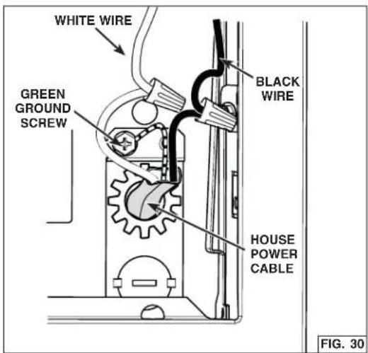
- Using appropriate wire nuts (not included), connect house power cable to unit wiring: BLACK to BLACK, WHITE to WHITE and GREEN or bare wire to GREEN ground screw (FIG. 30).
- Reinstall the electrical cover in the unit; ensuring the bottom tabs are inserted in their embossed location. Secure in place using its retaining screw (FIG. 31).
CAUTION
Take care not to pinch wires while reinstalling wiring cover.
INSTALL THE FILTERS
Ducted Installation
Reinstall the grease filters.
Non-Ducted Installation
Attach the non-ducted filters (included with the HARKBN30 non-duct kit) to the back of the grease filters using clips (provided with non-ducted filter). To order new non-ducted filters, use service part number S99010464-130.
text_image
WHITE WIRE GREEN GROUND SCREW BLACK WIRE HOUSE POWER CABLE FIG. 30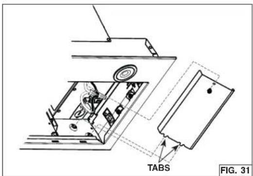
text_image
TABS FIG. 31OPERATION
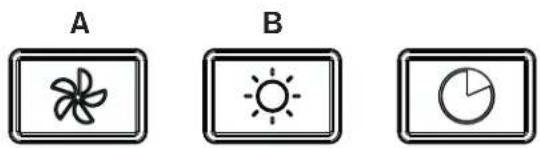
SOFT-TOUCH CONTROL

NOTES: 1. Each time a key is pressed, a beep is emitted to acknowledge the command. To disable, when the fan and lights are OFF, press on the Lights key (2) for 5 seconds. To put it back, when the fan and lights are OFF, press again on the Lights key (2) for 5 seconds.
- Each time a key is pressed, its backlight turns on. When a function is turned OFF, so does the corresponding key backlight.
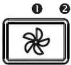
① Fan:
When fan is OFF, a key press turns ON the fan to the last saved speed. If there was no speed saved, the fan will be set on LOW speed. To change the fan speed, press the key again until the desired speed is reached (from LOW, to MEDIUM-LOW, to MEDIUM-HIGH, to HIGH speed to OFF).
When the fan is ON (no matter the speed level), a long key press turns the fan OFF and the current fan speed setting is saved to memory.
Filter Cleaning Reminder
When the user turns the fan OFF, and the fan key backlight flashes slowly during 30 seconds, then this means it is time to clean the hood and filters. Refer to the Maintenance and Cleaning Section on page 18. This will happen every time the user turns the fan OFF (and the timer has not been reset).
Once the cleaning is done, at any time during the 30-second signal (and the fan is OFF), a long press on the fan key will reset the timer and stop the key backlight flashing.
HEAT SENTRY™
Your unit is equipped with a HEAT SENTRY™ thermostat. This thermostat is a device that will turn on or speed up the blower if it senses excessive heat above the cooking surface.
1) If blower is OFF - it turns blower ON to HIGH speed. 2) If blower is ON at a lower speed setting - it turns blower up to HIGH speed.
When the temperature level drops to normal, the blower will return to its original setting.
NOTE: When Heat Sentry is activated, the fan key backlight flashes slowly and the fan speed cannot be changed.
WARNING
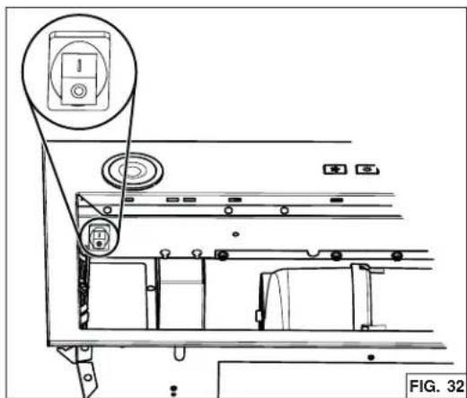
The HEAT SENTRY thermostat can start the blower even if the hood is turned OFF. When this occurs, it is not possible to turn the blower OFF with the control. If you must stop the blower, set the main power switch (located behind the filters, on inner side of the unit faceplate) in OFF position (if it is possible to do so safely). See inset in FIG. 32.
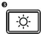
② Lights:
Press this key to turn ON the lights to the last saved intensity. If there was no light intensity saved, the lights will be set on LOW intensity. Press another time to set the lights to HIGH intensity. Pressing another time after the HIGH intensity will turn OFF the light.
When the lights are ON, a long press turns the lights OFF and the current light intensity is saved to memory. The next time the lights are turned ON, it does so at the last saved intensity.
③ Delay OFF:
When fan is ON, press this key to activate the delay function; the delay off key backlight will be ON for the duration of the delay (or until cancelled). The fan will continue to operate for 10 minutes and then, will shut off automatically.
When the delay mode is active, it is possible to change the fan speed by pressing the fan key without affecting the remaining time of the delay.
To cancel the delay function before the end of the 10 minute-cycle, press again on the delay OFF key or turn OFF fan using fan key.
natural_image
Technical line drawing of a mechanical assembly with no visible text or symbolsOPERATION (CON'T)
CODE READY™ TECHNOLOGY ACTIVATION
The Code Ready Technology option allows to change the blower output from the 600 CFM factory setting to a maximum of 400 CFM or 300 CFM. Activating the CRT option will reduce the airflow, so that the powerpack insert will perform within the allowable limit of Make-Up Air (MUA) codes (to meet some building code requirements). Do not change the blower CFM setting unless this change is required by code. This change will alter the performance of the product.
IMPORTANT NOTES: 1. This change CANNOT be reverted.
- CRT can only be set within the first 5 minutes of applying power to the unit.
- A power outage will not deactivate the CRT.
- Fan and lights must be OFF.
CRT PROCEDURE
- Switch power ON using the main power switch (located behind the filters) and press simultaneously on Fan (A) and Lights (B) keys for 5 seconds; Fan (A) and Lights (B) key backlights will now flash to indicate you entered the CRT menu.
400 CFM MAXIMUM AIRFLOW
- To select the 400 CFM maximum airflow, press on the Fan (A) key for 5 seconds, then release; the Fan key backlight will now flash to indicate 400 CFM has been selected (the Light (B) key backlight will be shut).
- A second 5-second press on the Fan (A) key and release confirms the selection; the Fan key backlight quickly flashes twice, and the buzzer sounds a double beep. The user interface returns to normal operation.
- Locate the CRT sticker near the HVI Certification label inside the powerpack insert, behind the filters. Check the proper box (400 CFM).
300 CFM MAXIMUM AIRFLOW
- To select the 300 CFM maximum airflow, press on the Lights (B) key for 5 seconds, then release; the Lights key backlight will now flash to indicate 300 CFM has been selected (the Fan (A) key backlight will be shut).
- A second 5-second press on the Lights (B) key and release confirms the selection; the Lights key backlight quickly flashes twice, and the buzzer sounds a double beep. The user interface returns to normal operation.
- Locate the CRT sticker near the HVI Certification label inside the powerpack insert, behind the filters. Check the proper box (300 CFM).
MAINTENANCE
ALWAYS SWITCH OFF THE ELECTRICITY SUPPLY BEFORE CARRYING OUT ANY OPERATIONS ON THE APPLIANCE.
Grease Filters
The grease filters should be cleaned frequently. Use a warm dishwashing detergent solution. Grease filters are dishwasher safe.
Clean the filters in the dishwasher using a non-phosphate detergent. Discoloration of the filters may occur if using phosphate detergents, or as a result of local water conditions - but this will not affect filter performance. This discoloration is not covered by the warranty. To minimize or prevent discoloration, hand wash filters using a mild detergent.
Non-Ducted Recirculation Filters
The Non-Ducted Recirculation filters should be changed every 3 to 6 months. Replace more often if your cooking style generates extra grease, such as frying and wok cooking.
STAINLESS STEEL CLEANING
Do:
- Regularly wash with clean cloth or rag soaked with warm water and mild soap or liquid dish detergent.
• Always clean in the direction of original polish lines. - Always rinse well with clear water (2 or 3 times) after cleaning. Wipe dry completely.
- You may also use a specialized household stainless steel cleaner.
Don't:
- Use any steel or stainless steel wool or any other scrapers to remove stubborn dirt.
- Use any harsh or abrasive cleansers.
- Allow dirt to accumulate.
- Let plaster dust or any other construction residues reach the unit. During construction/ renovation, cover the unit to make sure no dust sticks to the stainless steel surface.
Avoid when choosing a detergent:
- Any cleaners that contain bleach will attack stainless steel.
- Any products containing: chloride, fluoride, iodide, bromide will deteriorate surfaces rapidly.
- Any combustible products used for cleaning such as acetone, alcohol, ether, benzol, etc., are highly explosive and should never be used close to a range.
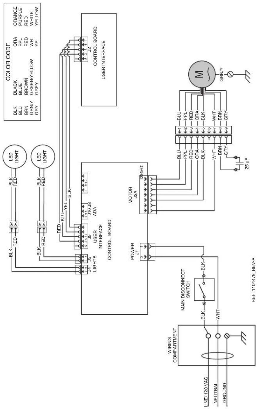
flowchart
graph TD
    A["LINE/120 VAC"] --> B["WIRING COMPARTMENT"]
    C["NEUTRAL"] --> D["MAIN DISCONNECT SWITCH"]
    E["GROUND"] --> F["WHT"]
    B --> G["BLK"]
    D --> H["BLK"]
    F --> I["BLK"]
    G --> J["RED"]
    H --> K["RED"]
    I --> L["RED"]
    J --> M["LED LIGHT"]
    K --> N["LED LIGHT"]
    L --> O["BLK"]
    M --> P["BLK"]
    N --> Q["RED"]
    O --> R["RED"]
    P --> S["RED"]
    Q --> T["BLU"]
    R --> U["YEL"]
    S --> V["BLK"]
    T --> W["BLK"]
    U --> X["BRN/Y GREEN/YELLOW WH WHITE"]
    V --> Y["GRY GREY YEL YELLOW"]
    Z["CONTROL BOARD"] --> AA["POWER J1"]
    AB["USER INTERFACE"] --> AC["MOTOR J2A"]
    AD["CONTROL BOARD"] --> AE["USER INTERFACE"]
    AF["REF: 1104478_REV-A"] --> AG["25 µF"]
    AH["COLOR CODE"] --> AI["BLK BLU BLK"]
    AJ["COOR CODE"] --> AK["ORA ORANGE BLU BLUE PPL PURPLE BRN BROWN RED RED GRN/Y GREEN/YELLOW WH WHITE GRY GREY YEL YELLOW"]
WIRING DIAGRAM
INSTALLATION AND USE & CARIE INSTRUCTIONS
text_image
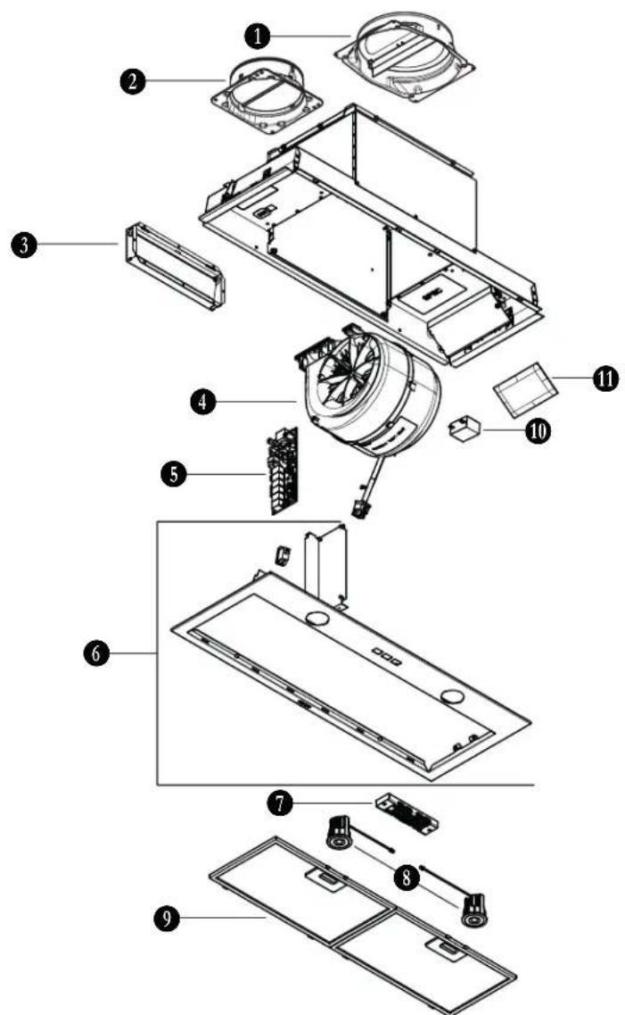
Exploded view diagram of a refrigerator internal components with numbered labels| KEY NO. | PART NUMBER | DESCRIPTION | QTY. |
| 1 | SV24383 | 8-IN, ROUND ADAPTER / DAMPER | 1 |
| 2 | SV08487 | 6-IN, ROUND ADAPTER / DAMPER | 1 |
| 3 | SR740014 | 314" × 10" ADAPTER / DAMPER | 1 |
| 4 | S97021509 | BLOWER ASS'Y 600 CFM | 1 |
| 5 | S1108581 | MAIN PCB | 1 |
| 6 | S98012198-811 | FACEPLATE | 1 |
| 7 | S1108582 | SOFT TOUCH 3-BUTTON CONTROL | 1 |
| 8 | S99271694 | LED MODULE ASSEMBLY (PAIR) | 1 |
| 9 | S99010400-130 | MICROMESH GREASE FILTERS (PAIR) | 1 |
| 10 | S99271379 | CAPACITOR 25 F | 1 |
| 11 S1 | 104978 | PARTS BAG INCLUDING : 4 No. 8-18 x 1/4" METAL SCREWS,4 No. 8-32 x 1/4" METAL SCREWS,8 No. 8 x 5/8" ROUND HEAD WOOD SCREWS, | 1 |
| 12 S9 | 9010464-130 | CHARCOAL FILTERS WITH CLIPS (NON-DUCTED INSTALLATION ONLY,INCLUDED IN NON-DUCT KIT NO. HARKBN30) (NOT SHOWN) (PAIR) | 1 |
Limited Warranty
Warranty Period and Exclusions: Broan-NuTone LLC and Venmar Ventilation ULC (either being the "Company") warrants to the original consumer purchaser of its product ("you") that the product (the "Product") will be free from material defects in the Product or its workmanship for a period of one (1) year from the date of original purchase (or such longer period as may be required by applicable law). For Range Hood Product that includes built-in LED modules, the Company warrants the LED modules and driver to be free from material defects for a period of three (3) years from the date of purchase. The limited warranty period for any replacement parts provided by the Company and for any Products repaired or replaced under this limited warranty shall be the remainder of the original warranty period (or such longer period as may be required by applicable law).
This warranty does not cover fluorescent lamp starters, tubes, halogen, incandescent and LED bulbs, fuses, filters, ducts, roof caps, wall caps and other accessories for ducting that may be purchased separately and installed with the Product. This warranty also does not cover (a) normal maintenance and service, (b) normal wear and tear, (c) any Products or parts which have been subject to misuse, abuse, abnormal usage, negligence, accident, improper or insufficient maintenance, storage or repair (other than repair by the Company), (d) damage caused by faulty installation, or installation or use contrary to recommendations or instructions, (e) any Product that has been moved from its original point of installation, (f) damage caused by environmental or natural elements, (g) damage in transit, (h) natural wear of finish, (i) Products in commercial or nonresidential use, or (j) damage caused by fire, flood or other act of God or (k) Products with altered, defaced or removed serial numbers. This warranty covers only Products sold to original consumers in the United States and Canada by the Company or its U.S. and Canadian distributors authorized by the Company.
This warranty supersedes all prior warranties and, subject to applicable law, is not transferable from the original consumer purchaser.
No Other Warranties: This Limited Warranty contains the Company's sole obligation and your sole remedy for defective products. The foregoing warranties are exclusive and in lieu of any other warranties and conditions, express or implied. THE COMPANY DISCLAIMS AND EXCLUDES ALL OTHER EXPRESS WARRANTIES AND CONDITIONS, AND DISCLAIMS AND EXCLUDES ALL WARRANTIES AND CONDITIONS IMPLIED BY LAW, INCLUDING WITHOUT LIMITATION THOSE OF MERCHANTABILITY AND FITNESS FOR A PARTICULAR PURPOSE. To the extent
that applicable law prohibits the exclusion of implied warranties or conditions, the duration of any applicable implied warranty or condition is limited to the period specified for the express warranty above. Some jurisdictions do not allow limitations on how long an implied warranty lasts, so the above limitation may not apply to you. Any oral or written description of the Product is for the sole purpose of identifying it and shall not be construed as an express warranty.
Whenever possible, each provision of this Limited Warranty shall be interpreted in such manner as to be effective and valid under applicable law, but if any provision is held to be prohibited or invalid, such provision shall be ineffective only to the extent of such prohibition or invalidity, without invalidating the remainder of such provision or the other remaining provisions of the Limited Warranty.
Remedy: During the applicable limited warranty period, the Company will, at its option, provide replacement parts for, or repair or replace, without charge, any Product or part thereof, to the extent the Company finds it to be covered by and in breach of this limited warranty under normal use and service. The Company will ship the repaired or replaced Product or replacement parts to you at no charge. You are responsible for all costs for removal, reinstallation and shipping, insurance or other freight charges incurred in the shipment of the Product or part to the Company. If you must send the Product or part to the Company, as instructed by the Company, you must properly pack the Product or part—the Company is not responsible for damage in transit. The Company reserves the right to utilize reconditioned, refurbished, repaired or remanufactured Products or parts in the warranty repair or replacement process. Such Products and parts will be comparable in function and performance to an original Product or part and warranted for the remainder of the original warranty period (or such longer period as may be required by applicable law).
Company reserves the right, in its sole discretion, to refund the money actually paid by you for the Product in lieu of repair or replacement. If the Product or component is no longer available, replacement may be made with a similar product of equal or greater value, at Company's sole discretion. This is your sole and exclusive remedy for breach of this limited warranty.
Exclusion of Damages: THE COMPANY'S OBLIGATION TO PROVIDE REPLACEMENT PARTS, OR REPAIR, REPLACE OR REFUND, AT THE COMPANY'S OPTION, SHALL BE YOUR SOLE AND EXCLUSIVE REMEDY UNDER THIS LIMITED WARRANTY AND THE COMPANY'S SOLE AND EXCLUSIVE OBLIGATION. THE COMPANY SHALL NOT BE LIABLE FOR INCIDENTAL, INDIRECT, CONSEQUENTIAL OR SPECIAL DAMAGES ARISING OUT OF OR IN CONNECTION WITH THE PRODUCT, ITS USE OR PERFORMANCE. Incidental damages include but are not limited to such damages as loss of time and loss of use. Consequential damages include but are not limited to the cost of repairing or replacing other property which was damaged if the Product does not work properly.
THE COMPANY SHALL NOT BE LIABLE TO YOU, OR TO ANYONE CLAIMING UNDER YOU, FOR ANY OTHER OBLIGATIONS OR LIABILITIES, INCLUDING, BUT NOT LIMITED TO, OBLIGATIONS OR LIABILITIES ARISING OUT OF BREACH OF CONTRACT OR WARRANTY, NEGLIGENCE OR OTHER TORT OR ANY THEORY OF STRICT LIABILITY, WITH RESPECT TO THE PRODUCT OR THE COMPANY'S ACTS OR OMISSIONS OR OTHERWISE.
Some jurisdictions do not allow the exclusion or limitation of incidental or consequential damages, so the above limitation or exclusion may not apply to you. This warranty gives you specific legal rights, and you may also have other rights, which vary from jurisdiction to jurisdiction. The disclaimers, exclusions, and limitations of liability under this warranty will not apply to the extent prohibited by applicable law.
This warranty covers only replacement or repair of defective Products or parts thereof at the Company's main facility and does not include the cost of field service travel and living expenses.
Any assistance the Company provides to or procures for you outside the terms, limitations or exclusions of this limited warranty will not constitute a waiver of such terms, limitations or exclusions, nor will such assistance extend or revive the warranty.
The Company will not reimburse you for any expenses incurred by you in repairing or replacing any defective Product, except for those incurred with the Company's prior written permission.
How to Obtain Warranty Service: To qualify for warranty service, you must (a) notify the Company at the address or telephone number stated below within seven (7) days of discovering the covered defect, (b) give the model number and part identification and (c) describe the nature of any defect in the Product or part. At the time of requesting warranty service, you must present evidence of the original purchase date. If you cannot provide a copy of the original written limited warranty, then the terms of the Company's most current written limited warranty for your particular product will control.
The most current limited written warranties for the Company's products can be found at www.broan-nutone.com and www.broan-nutone.ca.
Broan-NuTone LLC 926 West State Street, Hartford, Wisconsin, USA 53027 Broan-NuTone.com 800-558-1711
Venmar Ventilation ULC, 550 Lemire Blvd., Drummondville, Québec, Canada J2C 7W9 Broan-NuTone.ca 800-567-3855
Hottes encastrées
Numéros de modèle :
BBN3306SS, BBN3306SSC
DIRECTIVES D'INSTALLATION, D'UTILISATION ET D'ENTRETIEN
natural_image
Technical line drawing of a mechanical enclosure or enclosure with internal compartments and mounting brackets (no text or symbols)Sécurité....3-4
Installation....5-15
Au Canada : broan-nutone.ca
natural_image
Technical line drawing of a mechanical device with central circular component and mounting base (no text or symbols)RETRAIT DES SUPPORTS D'ARMOIRE
text_image
VIS FIG. 3text_image
C D C FIG. 7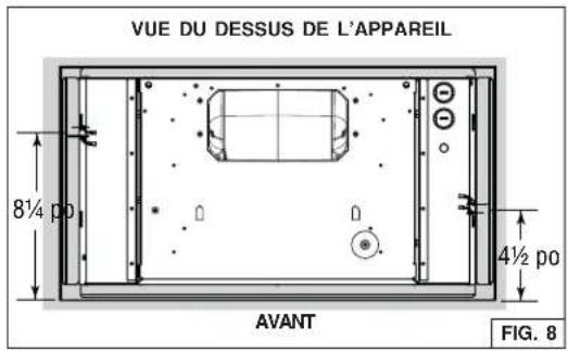
text_image
VUE DU DESSUS DE L'APPAREIL 8½ p0 AVANT 4½ p0 FIG. 8PRÉPARATION DE L'ARMOIRE (SUITE)
natural_image
Technical diagram showing two mechanical components with a dimension label 'F' between them, no readable text or symbols present.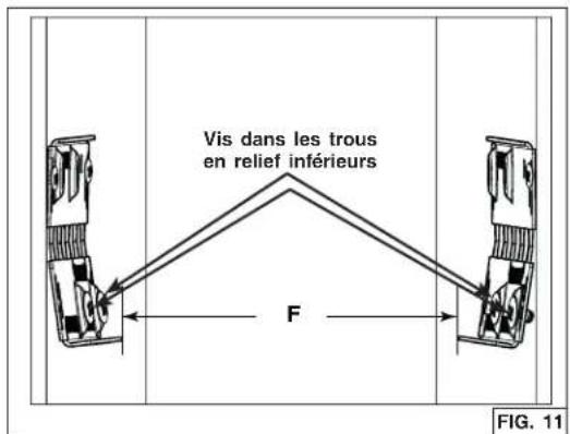
natural_image
Technical diagram of a 3D floor plan with no visible text or symbols, including a prohibition symbol below (no text or labels present)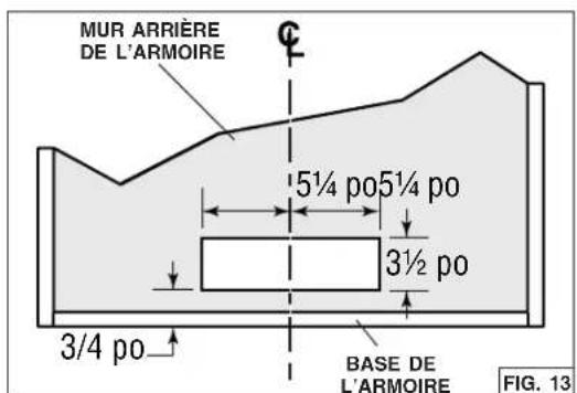
text_image
MUR ARRIÈRE DE L'ARMOIRE 5½ po 5½ po 3½ po 3/4 po BASE DE L'ARMOIRE FIG. 13PRÉPARATION DE L'APPAREIL
TOUTES LES INSTALLATIONS
natural_image
Technical line drawing of a cabinet or enclosure with doors and control knobs, showing internal components and a directional arrow (no text or symbols)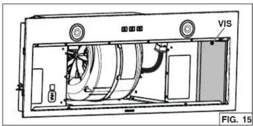
natural_image
Technical line drawing of a device interior with labeled components (no readable text or symbols)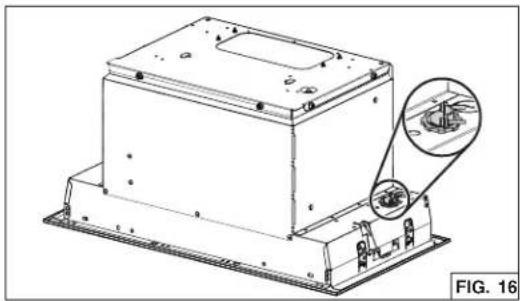
natural_image
Technical line drawing of a mechanical housing component with an inset close-up showing internal components (no text or symbols)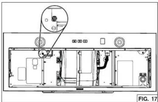
natural_image
Interior view of a computer monitor chassis showing internal components and a close-up of the screen (no text or symbols visible)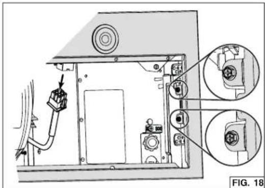
natural_image
Technical diagram of a device rear panel with labeled components and zoomed-in insets (no readable text or symbols)PRÉPARATION DE L'APPAREIL (SUITE)
INSTALLATION EN ÉVACUATION HORIZONTALE SEULEMENT (SUITE)
text_image
VIS VIS VIS FIG. 19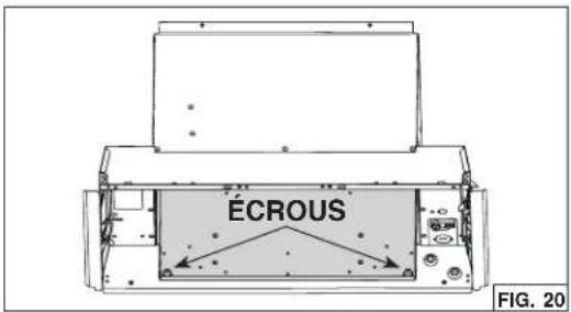
text_image
ECROUS FIG. 20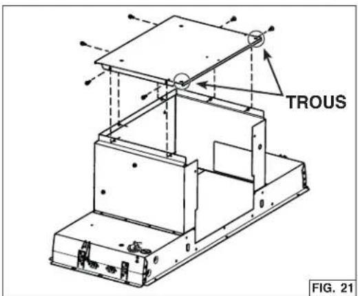
text_image
TROUS FIG. 21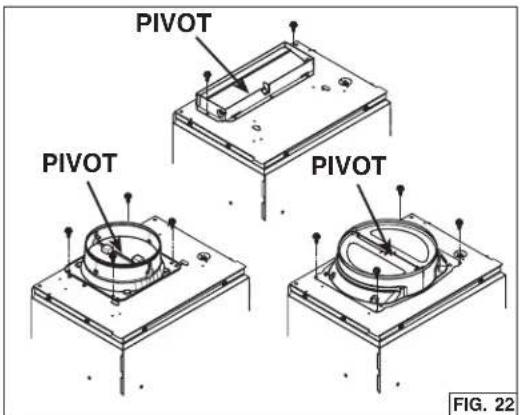
text_image
PIVOT PIVOT PIVOT FIG. 22INSTALLATION DE L'APPAREIL
text_image
Technical diagram illustrating three-step assembly steps of a mechanical device, labeled ① to ③ with directional arrows and magnified views.natural_image
Technical diagram of an electronic device showing internal components and wiring, with no readable text or symbols.RACCORDEMENT DU CONDUIT
INSTALLATION EN ÉVACUATION VERTICALE SEULEMENT
natural_image
Technical illustration showing a cylindrical component being lifted by a rectangular box, with a mechanical component below (no text or symbols)BRANCHEMENT ÉLECTRIQUE
AVERTISSEMENT
natural_image
Technical line drawing of a mechanical assembly with labeled components (no readable text or symbols)FONCTIONNEMENT (SUITE)
ACTIVATION DE L'OPTION CODE READY ^MC TECHNOLOGY
text_image
Exploded view diagram of a refrigerator internal components with numbered labels| REPÈRE | N° DE PIÈCE | DESCRIPTION | QTÉ |
| 1 | SV24383 | ADAPTATEUR/VOLET 8 PO ROND | 1 |
| 2 | SV08487 | ADAPTATEUR/VOLET 6 PO ROND | 1 |
| 3 | SR740014 | ADAPTATEUR/VOLET 314 po x 10 po | 1 |
| 4 | S97021509 | VENTILATEUR 600 P^3/MIN | 1 |
| 5 | S1108581 | CARTE ÉLECTRONIQUE PRINCIPALE | 1 |
| 6 | S98012198-811 | CHÂSSIS | 1 |
| 7 | S1108582 | COMMANDE À EFFLEUREMENT 3 BOUTONS | 1 |
| 8 | S99271694 | ENSEMBLES DE MODULE DEL (PAIRE) | 1 |
| 9 | S99010400-130 | FILTRES À GRAISSES À MAILLAGE FIN (PAIRE) | 1 |
| 10 | S99271379 | CONDENSATEUR 25 μF | 1 |
| 11 S1 | 104978 | SAC DE PIÈCES INCLUANT : 4 VIS À MÉTAUX N° 8-18 x 1/4 po,4 VIS MÉCANIQUES N° 8-32 x 1/4 po, 8 VIS À BOIS À TÊTE CYLINDRIQUE LARGEN° 8-15 x 5/8 po. | 1 |
| 12 S9 | 9010464-130 | FILTRES AU CHARBON AVEC CLIPS (INSTALLATION SANS CONDUIT SEULEMENT,INCLUS DANS LE KIT DE RECIRCULATION N° HARKBN30) (NON ILLUSTRÉS)(PAIRE) | 1 |
Garantie limitée
Broan-NuTone LLC 926 West State Street, Hartford, Wisconsin, USA 53027 Broan-NuTone.com 800-558-1711
Venmar Ventilation ULC, 550 Lemire Blvd., Drummondville, Québec, Canada J2C 7W9 Broan-NuTone.ca 800-567-3855
Campanas empotrables
Números de modelo :
BBN3306SS, BBN3306SSC
natural_image
Technical line drawing of a mechanical enclosure or enclosure with internal compartments and mounting feet (no text or symbols)Seguridad 3-4
Instalación....5-15
natural_image
Technical line drawing of a mechanical device with central circular component and mounting base (no text or symbols)RETIRADA DE LOS SOPORTES DE GABINETE
text_image
C D C FIG. 7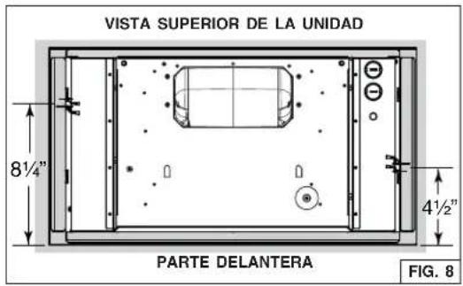
text_image
VISTA SUPERIOR DE LA UNIDAD 8½" 4½" PARTE DELANTERA FIG. 8natural_image
Technical diagram showing two mechanical components with a force F applied, no text or symbols present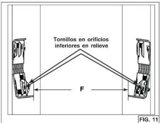
natural_image
Architectural diagram of a roof structure with no visible text or symbols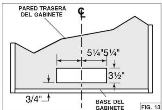
text_image
PARED TRASERA DEL GABINETE 5½"5½" 3½" 3/4" BASE DEL GABINETE FIG. 13natural_image
Technical line drawing of a door frame with doors, switches, and a handle (no text or symbols)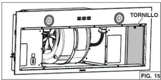
text_image
TORNILLO FIG. 15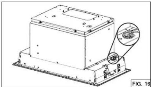
natural_image
Technical line drawing of a mechanical housing component with an inset showing internal components (no text or symbols)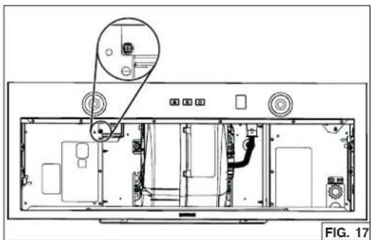
natural_image
Technical diagram of an open rear panel with internal components and a magnified inset showing a component detail (no text or symbols present)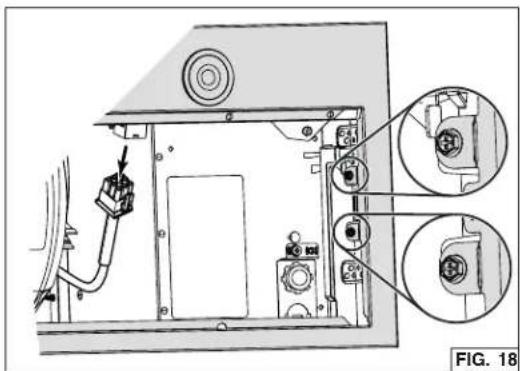
natural_image
Technical diagram of an electronic device showing internal components and wiring (no text or symbols)text_image
Technical diagram illustrating three-step assembly steps of a mechanical device, labeled ① to ③ with directional arrows and magnified views.natural_image
Technical diagram of an electronic device showing internal components and wiring, with no readable text or symbols.natural_image
Technical illustration showing three stages of a mechanical assembly: cylinder, box, and base plate (no text or symbols)CONEXIÓN ELÉCTRICA

ADVERTENCIA
natural_image
Technical line drawing of a mechanical assembly with labeled components (no readable text or symbols)text_image
Exploded view diagram of a refrigerator internal components with numbered labels| N.° | N.° DE PIEZA | DESCRIPCIÓN | CANT. |
| 1 | SV24383 | ADAPTADOR/COMPUERTA 8 PULG. REDONDO | 1 |
| 2 | SV08487 | ADAPTADOR/COMPUERTA 6 PULG. REDONDO | 1 |
| 3 | SR740014 | ADAPTADOR/COMPUERTA 314 PULG. x 10 PULG. | 1 |
| 4 | S97021509 | VENTILADOR 600 PI ^3 /MIN | 1 |
| 5 | S1108581 | PLACA PRINCIPAL DE CIRCUITOS | 1 |
| 6 | S98012198-811 | PANEL FRONTAL | 1 |
| 7 | S1108582 | CONTROL TÁCTIL CON 3 TECLAS | 1 |
| 8 | S99271694 | CONJUNTO DE MÓDULO LED (PAR) | 1 |
| 9 | S99010400-130 | FILTROS DE GRASA CON MALLA FINA (PAR) | 1 |
| 10 | S99271379 | CONDENSADOR 25 μF | 1 |
| 11 S | 1104978 | BOLSA DE PIEZAS QUE INCLUYE: 4 TORNILLOS PARA METALES N° 8-18 x 1/4 PULG.,8 TORNILLOS PARA MADERA N° 8 x 5/8 PULG. DE CABEZA TROCOCÓNICA,4 TORNILLOS PARA METALES NO. 8-32 x 1/4 PULG. | 1 |
| 12 | S99010464-130 | FILTROS DE CARBÓN CON CLIPS (NO ILLUSTRADOS) (PARA INSTALACIÓN SIN CONDUCTOSOLAMENTE, INCLUIDO EN EL KIT DE RECIRCULACIÓN N.° HARKBN30) (PAR) | 1 |
Garantía limitada
Broan-NuTone LLC 926 West State Street, Hartford, Wisconsin, USA 53027 Broan-NuTone.com 800-558-1711
Venmar Ventilation ULC, 550 Lemire Blvd., Drummondville, Québec, Canada J2C 7W9 Broan-NuTone.ca 800-567-3855