MCS T16 - Air Conditioning DOMETIC - Free user manual and instructions
Find the device manual for free MCS T16 DOMETIC in PDF.


User questions about MCS T16 DOMETIC
0 question about this device. Answer the ones you know or ask your own.
Ask a new question about this device
Download the instructions for your Air Conditioning in PDF format for free! Find your manual MCS T16 - DOMETIC and take your electronic device back in hand. On this page are published all the documents necessary for the use of your device. MCS T16 by DOMETIC.
USER MANUAL MCS T16 DOMETIC
natural_image
Technical line drawing of an industrial mechanical assembly (no text or symbols visible)MCS T6, MCS T12, MCS T16
EN
Marine Air Conditioner
Operating manual 4
DE
Bootsklimaanlage
Please read this instruction manual carefully before first use, and store it in a safe place. If you pass on the product to another person, hand over this instruction manual along with it.
Contents
1 Explanation of symbols....5
2 Safety instructions....5
3 Target group for this manual. 6
4 Proper use ....6
5 Technical description ....6
6 Operating elements 7
7 Operating 8
8 Programming 15
9 Troubleshooting 24
10 Maintenance 32
11 Warranty 35
12 Disposal.... 35
13 Technical data 36
1 Explanation of symbols

WARNING!
Safety instruction: Failure to observe this instruction can cause fatal or serious injury.

CAUTION!
Safety instruction: Failure to observe this instruction can lead to injury.

NOTICE!
Failure to observe this instruction can cause material damage and impair the function of the product.

NOTE
Supplementary information for operating the product.
2 Safety instructions
The manufacturer accepts no liability for damage in the following cases:
• Faulty assembly or connection
• Damage to the product resulting from mechanical influences and excess voltage
• Alterations to the product without express permission from the manufacturer
• Use for purposes other than those described in the operating manual
2.1 General safety

CAUTION!
• Electronic devices are not toys!
Keep electrical appliances out of reach from children or infirm persons.
Do not let them use the appliances without supervision.
- Persons (including children) whose physical, sensory or mental capabilities or lack of experience and knowledge prevents them from using the appliance safely should not use this appliance without initial supervision or instruction by a responsible person.
• Use the device only as intended.
- Do not make any alterations or conversions to the device.
- Installation and repairing of the air conditioner may only be carried out by qualified personnel who are familiar with the risks involved and the relevant regulations. Inadequate repairs can lead to considerable hazards. For repair service, please contact the service centre in your country (addresses on the back).
3 Target group for this manual
This operating manual is for air conditioner users.
4 P r o p e r u s c
The Marine Climate System is an air conditioning system designed for use on boats or yachts. It can cool down or warm up the interior of the boat or yacht.
5 Technical description
The Marine Climate Systems MCS T6, MCS T12 and MCS T16 are marine air conditioners which can be used for variable air conditioning inside a boat or a yacht. They can cool and warm the room.
The Marine Climate System consists mainly of the air conditioning unit and a control panel. A refrigerant is circulating through the system which is seawater cooled.
6 Operating elements
6.1 Control Panel
Key to fig. 1, page 3:
| Item Name Description | |
| 1 Power Button Press and release to toggle between the On and Off Modes. | |
| 2 Fan Button | Press to advance through the available fan settings. “1”(lowest) through “6” (highest) indicates Manual Fan Speeds.The letter “a” indicates automatic fan operation selected. |
| 3 Down Button Press and release to display the set point.Press and hold the Down Button to decrease the set point. Set point is decreased 0.5 °C or 1 °F each time the button is depressed. | |
| 4 Faceplate sensor The faceplate sensor will read the room temperature unless a remote air sensor is installed. | |
| 5 Up Button Press and release to display the set point.Press and hold the Up Button to increase the set point. Set point is increased 0.5 °C or 1 °F each time the button is depressed. | |
| 6 Display The inside air temperature is displayed when the control is on.The set point is displayed when either Up or Down Button is pressed.The display also indicates program information and fault codes.When the control resumes operation after a power interruption all the display LEDs will turn on for one second. This is normal operating condition and is referred to as Power On Reset. | |
| 7 LED “Heat Mode” | This LED is lit when– the Heat Only Mode is selected– or the unit is in a heating cycle. |
| 8 LED “Fan Indicator” | This LED is lit when a Manual Fan Speed is selected. |
| 9 LED “Cool Mode” | This LED is lit when– the Cool Only Mode is selected– or when the unit is in a cooling cycle. |
6.2 Dual Button Functions
Up and Down Buttons
- While in the On Mode: Simultaneously press the Up and Down Buttons to display outside air temperature providing the optional outside air temperature sensor is installed.
- While in the Program Mode: Simultaneously press the Up and Down Buttons to set new program defaults.
Power and Down Buttons
- While viewing the service fault history log: Simultaneously press the Power and Down Buttons to clear the fault history log (see "Service History Log" on page 14).
- While in the On Mode: Simultaneously press the Power and Down Buttons to enter the Dehumidification Mode (see "Dehumidification Mode" on page 11).
7 O p e r a t i n g
7.1 Initial startup

NOTICE!
Do not turn the unit off and immediately turn it back on. Allow at least 30 s for refrigerant pressure equalization.
▶Ensure seawater intake ball valve (seacock) is open.
▶Turn on air conditioner circuit breaker.
▶ If the seawater pump has its own circuit breaker, turn that on.
▶ Press the Fan Button (fig. 1 2, page 3).
√This energizes the fan.
▶ Verify that the fan is running and that there is steady airflow out of the supply-air grille.
▶Select a temperature set point lower than the current cabin temperature.
√This starts the compressor and seawater pump.
▶Check for a steady solid stream of seawater from the overboard discharge.
▶If the unit does not appear to be operating properly, refer to troubleshooting guidelines ("Troubleshooting" on page 24).
7.2 Overview
Power On
▶ Press the Power button (fig. 1 1, page 3) once to engage the system.
√ The display indicates room temperature when the system is on and is blank when the system is off.
Set Temperature
▶ Press the Up or Down button (fig. 1 3 and 4, page 3) to set the desired room temperature.
The set point can be viewed by momentarily pressing and releasing the Up or Down button.
Fan Speed
Fan-speed operation is automatic, allowing fan speed to decrease as the set point temperature is approached in the Cool Mode. The fan operates at low speed when set point is satisfied.
▶ Use the Fan button (fig. 1 2, page 3) to select manual fan speeds.
You can program the fan to run only when cooling or heating is required. Normally the automatic fan-speed operation is reversed in the Heating Mode, however, the fan can be programmed to operate the same as in the Cooling Mode.
Memory
The control's nonvolatile memory requires no batteries or backup power. When power is lost, the operating parameters are retained indefinitely. When power is restored, the control resumes operating as last programmed.
7.3 Modes of Operation
Off Mode
When the Marine Climate System is in the Off Mode, all control outputs are turned off. Program parameters and user settings are saved in nonvolatile memory.
On Mode
When the Marine Climate System is in the On Mode, power is supplied to the appropriate outputs and the display indicates the current state of operation. The operating and program parameters resume based on those stored the last time the unit was operating.
Cool Mode
When Cool Mode is selected, the Cool Mode LED is lit and the cooling systems are operated as required. When the temperature drops below the set point, the system will not automatically switch to the Heat Mode.
Heat Mode
When the Heat Mode LED is lit, only the heating systems are selected and operated as required. Should the temperature rise above the set point, the system will not automatically switch to the Cool Mode.
Automatic Mode
Automatic Mode provides both heating and cooling as required. The Heat or Cool LED will be lit according to the mode required.
Temperature in a given mode is maintained within 1.1 °C (2 °F) of set point, however a 2.2 °C (4 °F) difference is required to allow the Marine Climate System to change modes.
Once the mode changes temperature will be maintained within 1.1 ^ ( 2 ^ ) of set point.
Manual Fan Mode
Manual Fan Mode allows to select the desired fan speed manually. When a manual fan speed has been selected, the Fan LED will be lit. Manual Fan Mode is sometimes preferred when room temperature is constantly changing due to varying heat loads.
The fastest fan speed is represented by "6", the slowest represented by "1".
▶ Press and hold the Fan Button during normal operation to select one of the six manual fan speeds available.
Circulation Mode
When the system is off at the control panel the fan can be used to only circulate the air.
▶ Press and hold the Fan Button when the display is off until the desired speed number appears in the window.
▶Release the Fan Button.
√The fan will run at the selected speed circulating the air without heating or cooling.
▶ Press the Power Button once to cancel the Circulation Mode and enter the On Mode.
Dehumidification Mode
▶While in the On Mode simultaneously press the Power and Down Buttons.
√The first cycle will start in one minute.
▶Press the Power Button to end the Dehumidification Mode.
√The "HU1" mnemonic code is displayed while in the Dehumidification Mode.
Program Mode

NOTE
The program mode can only be entered from the Off Mode.
The Program Mode is used to adjust the systems operating parameters to suit the particular needs of individual users. The Program Mode is also used to tailor the air conditioning system for the most efficient operation within an installation.
Variables such as ducting, sensor location and system layout affect the system operation. The Marine Climate System is shipped with factory default settings which are stored in permanent memory and can be recalled at any time.
7.4 Operating the Marine Climate System

NOTICE!
Do not turn the unit off and immediately turn it back on. Allow at least 30 s for refrigerant pressure equalization.

NOTE
When powering on the Marine Climate System, press and immediately release the Power Button in order to not unintentionally entering Program Mode.
If the Program Mode is entered unintentionally, any subsequent presses of the Up or Down Button will change the P-1 parameter setting, which can result in improper system operation.
▶ Press the Power Button (fig. 1 1, page 3) shortly to engage the system.
√ The display indicates room temperature when the system is on and is blank when the system is off.
▶ Press the Down Button (fig. 1 3, page 3) or Up Button (fig. 1 5, page 3) to choose the desired set point.
√ The display indicates room temperature when the system is on and is blank when the system is off.
√The thermostat is now set to maintain a constant temperature.
▶ Set the desired room temperature by pressing the Up or Down Button.
The set point can be viewed by momentarily pressing and releasing the Up or Down Button.
The Marine Climate System has nonvolatile memory requiring no batteries or backup power. When power is lost the operating parameters are retained indefinitely. When power is restored, the Marine Climate System resumes operating as last programmed.
Automatic fan speed operation allows fan speed to decrease as room temperature is approached in the Cool Mode. The fan will operate at low speed when set point is satisfied.
Manual fan speeds can be selected with the Fan Button.
The fan can be programmed to run only when cooling or heating is required. Normally the automatic fan speed operation is reversed in the Heating Mode, however, the fan can be programmed to operate the same as in the Cooling Mode.
7.5 Automated Factory Self Test Program
The Marine Climate System software provides a self test program to facilitate factory testing of the entire air conditioning system. Once the self test program is activated, the test cycle will continue until the AC power is interrupted or the Power Button is pressed once which returns the system to the Off Mode.
▶ Activate the self test program by pressing the Power Button while turning on the AC power.
▶Release the Power Button while the display indicates "888" and all LEDs are lit.
√The Marine Climate System is now in the self test program.
√"tSt" appears in the display while in the self test program.
Once activated the self test software will continuously execute the following procedure:
• Turn on in the Heat Mode and supply heating for 10 min.
- Stop heating and run the fan only for 5 min.
- Switch to Cool Mode and continue cooling for 10 min.
- Stop cooling and run the fan only for 5 min.
• Return to step one and continue until interrupted.
The self test program will continue until the power is interrupted or the test is halted by pressing the Power Button once.
7.6 Service Tools
Hour Meter
Total compressor cycle time is saved in EEPROM every six minutes of continuous compressor running time. Cycles less than six minutes are discarded to conserve memory and allow the most flexible hour-meter possible.
To view the hour meter proceed as follows:
▶Turn off the AC power.
▶Press the Down Button and hold it.
▶Restore AC power.
√ After Power-On Reset is complete, the following appears in the display:
- "Hr" is displayed for one second.
- The display blanks out for one second then displays the thousands of hours for three seconds.
- The display blanks out for one second then displays the hundreds units for three seconds.
√ The unit returns to the last operating state before power was removed.
Maximum recorded time is 65,536 hours, the meter stops and can only be reset by a service technician.
Service History Log
The Marine Climate System records and remembers the eight most recent faults. Each time a fault is detected, a one hour timer is started.
Three consecutive faults within that hour cause system shut down, lock out and display the fault code. During that hour, to conserve memory, the same recurring fault is not recorded in the service history log. Continuous operation for one hour without the same recurring fault clears that fault counter but the event remains in the service history log until overwritten. Should a different fault be detected during the hour, it will be entered into the service history log.
The following events are entered into the service history log:
• High Freon Pressure
- Low Freon Pressure
- Air Sensor Fault
To view the service history log proceed as follows:
▶Turn off the AC power.
▶Press the Fan Button and hold it.
▶Turn on the AC power.
Once Power On Reset is completed (display indicates "888" and all LEDs are lit) release the Fan Button.
√ The display will flash the most recent fault detected, followed by the event chronology number.
▶ To view other events detected press either the Up or Down Button.
▶ To clear the service history log simultaneously press the Power and Down Buttons.
▶To exit the service history log
- press either the Power, the Up or the Down Buttons or - wait thirty seconds without pressing any button.
8 P r o g r a m m
8.1 Entering Program Mode
▶ Press and hold the Power Button while in the Off Mode until the letter "P" appears in the display.
√The characters "P1" followed by the parameter setting, appear in the display.
√The Marine Climate System is now in the Program Mode.

NOTE
The Marine Climate System will exit the Program Mode and return to the Off Mode if no programming is attempted for one minute.
8.2 Changing Program Parameters
▶Increment from one program parameter to the next by pressing the Fan Button.
▶Press the Up and Down Buttons to select the data or set the desired limits for the parameter being programmed.
8.3 Saving New Program Parameters

NOTE
Factory defaults shown in the "Programmable Parameters Table" on page 17 may be reset manually (see "Restore Memorized Default Settings" on page 17).
▶ Simultaneously press the Up and Down Buttons to save the new program parameters.
√This will set the new program defaults.
8.4 Exiting the Program Mode
There are two methods to exit the Program Mode.
▶Press the Power Button
√ The Marine Climate System will return to the Off Mode.
... Or
Do not press any buttons and do not attempt any program changes for one minute.
√ The Marine Climate System will exit the Program Mode.
8.5 Software Identification
The software version of the Marine Climate System is identified for one second prior to the exit from the Program Mode. The software identification number, e.g. ("A12") will appear in the display for one second, then the Marine Climate System will return to the Off Mode.

NOTE
Should there be any reason to contact Dometic about the system or programming the Marine Climate System be sure to have the software identification number and air conditioning unit serial number available. The serial number may be found on the typeplate.
8.6 Restore Memorized Default Settings
The memorized default settings can be restored as follows.
▶Enter the Program Mode.
▶Set P-17 to "rSt".
▶Exit the Program Mode.
√The software version number (e.g. "A12") appears in the display.
√ The memorized default settings are restored and the Marine Climate System returns to the Off Mode.
8.7 Programmable Parameters
Programmable Parameters Table
| Program number | Description | Default | Range | |
| P-1 Operating Mode 0 0 = Automatic mode | 1 = Cool only mode2 = Heat only mode | |||
| P-2 High Fan Speed Limit (arbitrary units) | 95 65 – 95 | |||
| P-3 Low Fan Speed Limit (arbitrary units) | 55 30 – 64 | |||
| P-4 Compressor Staging Time Delay | 15 5 – 135 s | |||
| P-5 Temperature Sensor Calibration | Ambient Temperature | Ambient 10 °F, -12,2 °C | ||
| P-6 | Failsafe | 3 | 0 = Minimum protection1 = Continuous, no display2 = Continuous, with display3 = Four failures, reset required | |
| P-7 Low AC Voltage Shut-down (Volts) | 115 V – OFF220/230 V – OFF | 75 – 105175 – 205 | ||
| P-8 De-Icing Cycle | 1 OFF | 1 = On with 5 °F, -15 °C faceplate sensor differential2 = On with 7 °F, -13,9 °C faceplate sensor differential | ||
| Program number | Description | Default | Range |
| P-9 High | Water Temperature Limit (°F) | OFF 100 – 150 | |
| P-10 Display | Brightness Control | 94 = Low | 13 = Maximum |
| P-11 | Display °F or °C | FF = Fahrenheit displayedC = Celsius displayed | |
| P-12 Cycle | Pump With Compressor or Continuous Pump | OFF OFF = Cycle with compressorOn = Continuous pump | |
| P-13 Reverse | Fan Speeds During Heating Mode | rEF nor = Normal fan operationrEF = Reversed fan in heating | |
| P-14 Continuous Fan or Cycle Fan with Compressor | con CYC = Cycle fan with compressorcon = Continuous fan operation | ||
| P-15 Reverse | Cycle Heating or Electric Heat Only Option Installed (cooling only units) | nor nor = Reverse cycle heatingELE = Electric heater installed | |
| P-16 Fan | Motor type selection Shaded Pole or Split Capacitor. | SC SP = Shaded pole fan motorSC = Split capacitor fan motor | |
| P-17 Reset | Memorized Programming Defaults | nor rSt = Reset defaultsnor = Normal | |
| P-18 Reserved for Future Option | - | - | |
| P-19 Reserved for Future Option | - | - | |
| P-20 Filter Threshold (x10 hours) | 00 00 – 250 | ||
| P-21 Current Filter Time (x10 hours) | x10 Hours Using Current Filter | - | |
| P-22 Voltage Calibration (Volts) AC Voltage | - | ||

NOTE
Should any programming problems or confusion occur, reset the Memorized Default Settings by entering the program mode and setting P-17 to "rSt".
If recent programming changes were made but not saved, the reset will return to the last saved defaults, which could differ from the factory defaults.
P-1: Operating Mode
The following operating modes can be selected:
• Automatic Mode by selecting "0"
• Cool Only Mode by selecting "1"
• Heat Only Mode by selecting "2"
P-2: High Fan Limit
The upper fan speed limit can be adjusted for various motors. The high fan limit is adjusted with the system installed and operating. The values range from 65 through 95, arbitrary units.
▶ Use the Up and Down Buttons to select the desired speed.
- Increase the number for a higher fan speed.
– Decrease the number to lower the fan speed.
P-3: Low Fan Limit
The low fan limit determines the lowest output allowed for the low fan speed. The values range from 30 through 64, arbitrary units.
▶ Use the Up and Down Buttons to select the low fan limit.
- Increase the number for a higher fan speed.
– Decrease the number to lower the fan speed.

NOTE
Once the high and low fan speed limits are set, the unit will automatically readjust the remaining speeds to produce three equally spaced fan speeds in both Automatic and Manual Fan Modes.
P-4: Compressor Staging Time Delay
The compressor staging delay is provided for installations where more than one system operates from the same power source. Setting different staging delays allows compressors to start at different times when power is interrupted.
Units should be staged 5 s apart. The minimum delay is 5 s and the maximum is 135 s.
P-5: Temperature Calibration
Use this feature to calibrate the ambient sensor.
▶Select P-5.
√The ambient temperature appears in the display.
▶ Use the Up and Down Buttons to set the correct reading.
√The temperature in the display will increase or decrease as required.
P-6: Failsafe Level
There are four failsafe levels (see "Failsafe and Fault Handling Codes" on page 28).
P-7: Low AC Voltage Shutdown
Use this feature to shut down the unit if the voltage drops to a dangerously low level.
By default it is off, but it can be set from 175 – 205. This feature works immediately at start up, but while running will require a 5 min delay before displaying a fault to prevent nuisances.
The fault code is "LAC".
P-8: De-Icing Cycle
The Marine Climate System is equipped with a de-icing cycle to prevent ice build up on the evaporator coil during extended periods of cooling operation. Installation variables such as grille sizes, length of ducting, insulation R factors and ambient temperatures determine the cooling run time required to achieve set point. Customer usage may substantially increase run times by operating the system with the hatches and doors open.
Programming an unrealistic set point (e.g. 18.3 °C/65 °F) and leaving the door open will usually cause the evaporator to ice up on warm humid days.
De-icing is accomplished by using an algorithm that closely monitors the room air temperature in repeating 10 min intervals during a cooling cycle.
The de-icing feature has two different, selectable behavior modes when it is used in conjunction with the control panel's built-in room air temperature sensor. It attempts to compensate for any temperature discrepancy that the faceplate sensor may experience. Although this discrepancy is not typical, installation variables such as where the control panel is placed inside the room (e.g. near an open door or in direct sunlight) can affect how accurately it can read the actual room temperature.
By default with P-8 set to "1" (ON), the algorithm is applied assuming the faceplate sensor may be reading the room temperature as much as 2.8 °C (5 °F) greater than the actual evaporator temperature.
With programmable parameter P-8 set to "2", the temperature differential that is applied to the faceplate sensor reading is increased to 3.9 °C (7 °F) for even more extreme installations. Setting P-8 to "2" should only be used if a setting of "1" does not prevent evaporator ice from forming.
Alternately, the installation of an optional alternate air temperature sensor (located in the return air path) will greatly increase the effectiveness of the de-icing feature, and this option should be considered whenever the faceplate sensor cannot read the room temperature accurately.
P-9: High Water Temperature Limit
Use this feature to shut down the unit if the water in condenser coil rises to a dangerously high level.
By default it is off, but it can be set between 100 and 150 °F.
The fault code is "PLF".
P-10: Display Brightness Control
The display brightness can be adjusted from 4 (dimmest) to 13 (brightest).
P-11: Fahrenheit or Celsius Selection
The default setting is "°F". Select "°C" for Celsius. Celsius readings are displayed in tenths, e.g. 22.2.
P-12: Cycle Pump With Compressor
The pump can also be programmed to operate continuously or cycle on demand.
▶To program continuous operation select "On".
P-13: Reverse Automatic Fan Speeds During Heating
The automatic fan speeds can be reversed during Heating Mode. The fan will speed up as the set point is approached. Lowering the fan speed when the cabin is cold increases head pressure and helps raise supply temperature. The fan switches to low speed when the set point is satisfied and the compressor cycles off.
Normal fan operation is represented by "nor".
▶To reverse fan speeds in heating, select "rEF".
P-14: Cycle Fan with Compressor
The fan can be programmed to run continuously when the system is on or can be allowed to cycle with the compressor.
The default is "con", continuous fan.
▶To cycle the fan with the compressor select "CYC".

NOTE
When used with optional electric heat the fan will remain on 4 min after the heater cycles off.
P-15: Reverse Cycle or Electric Heat
▶ Do not change the default parameter.
P-16: Fan Motor Selection

NOTE
The unit's High Velocity (HV) blower has a Split Capacitor (SC) fan motor. The default is "SC" in order for the blower to work at peak efficiency.
The fan motor can also be programmed to operate with shaded pole (SP).
▶To program operation with shaded pole fan motor select "SP".
P-17: Reset Memorized Defaults
The default programming parameters can be reset as follows:
▶Select "rSt".
√This restores the programmable parameters to the default values.
The default parameters listed in the “Programmable Parameters Table” on page 17 may be altered by the installing dealer or end user. Once new defaults are entered and memorized the factory defaults will be overwritten. The original factory program parameters as listed in the table may be restored manually.
P-18, P-19: Reserved for Future Option
P-20: Filter Threshold
This feature is to remind you to change the air filter on a unit. The units are x10 hours.
By default it is off, which is designated with a "00", but it can be set between 100 and 2500 hours. After the unit has reached its threshold time, it will display a "FIL" remind 1 s every 10 s.
P-21: Current Filter Time
This feature is used to display the amount of time the current filter has been on the unit. The units are x10 hours.
▶In order to reset this parameter, simply press the Up or Down Button.
P-22: Voltage Calibration
This feature displays the voltage reading as seen by the display. Calibrating this parameter will provide a more accurate voltage when calculating low voltage for P-7. It will display a live reading of the voltage.
▶Manipulate the reading by pressing the Up or Down Button.
9 Troubleshooting
9.1 General Troubleshooting
Problem Possible Reason Solution
| System will not start. Air conditioning unit circuit breaker is off. | Turn circuit breaker on at ship's panel. |
| Control is not turned on. Turn control on. | |
| Wrong wiring at terminal strip. Check wiring diagram and correct if necessary. | |
| Push-on butt connectors became disconnected during installation. | Disconnect power supply and open electric box.Check wiring diagram, correct if necessary. |
| Input line voltage is insufficient. Check power source (shore/generator) for proper voltage.Check wiring and terminals for proper sizes and connections.Verify with a volt-meter that the power at the unit is the same as the power source. | |
| Fan is not running. - See corresponding section in "Control Panel Troubleshooting" on page 30. | |
Problem Possible Reason Solution
No cooling or heating. Temperature set point is satisfied. Lower or raise set point.
| Obstructed seawater flow. Clean seawater strainer. | |
| Check for obstructions at speed scoop thru-hull inlet. Check for a good steady flow from the overboard discharge. | |
| Seawater pump may be air-locked. Remove hose from pump discharge to purge air from line. | |
| Loss refrigerant gas. Check air conditioning unit for refrigerant oil leakage. Call service technician. | |
| Seawater temperature too high for cooling or too low for heating. | Seawater temperature will directly affect air conditioning unit's efficiency. This air conditioning unit can effectively cool your boat in water temperature up to 32.2 °C (90 °F) and heat in water temperatures as low as 4.4 °C (40 °F). |
Problem Possible Reason Solution
| No cooling or heating (contn'd). | Fan coil is iced (in cooling). See below. | |
| Fan is not running. See corresponding section in “Control Panel Troubleshooting” on page 30. | ||
| Seawater plumbing is air-locked. Ensure that seawater plumbing is installed per the guidelines in the Installation Manual. | ||
| The Marine Climate System is programmed for Cool or Heat only, or mechanical control thermostat is rotated too far towards either Cooler or Warmer setting. | Set P-1 to the desired value or rotate the mechanical control thermostat. | |
| High pressure switch open (in cooling) due to improper seawater flow.Strainer or intake may be plugged, seacock may be closed. | Check seawater hose for kinks or col-lapses.Verify pump operation.Check pump circuit breaker if appli-cable. | |
| High pressure switch open (in heating) due to improper airflow. | Remove any obstructions in return air stream.Clean return air filter and grille.Check for crushed or restricted duct-ing (ducting must be as straight, smooth and taut as possible). | |
| High-pressure switch is open in heating mode. | System may cycle on high-pressure if seawater temperature is above 12.8 °C (55 °F). | |
| Compressor's thermal overload is open due to either of the above rea-sons. | Compressor needs to cool down.Turn system off for a while (it may take up to three hours to reset thermal overload). | |
| No cooling Control panel may not be in “cool” position. | Reset control panel. | |
| Coil iced. See below. | ||
| No heating. Unit is “cool only”, or if reverse cycle, reversing valve may be stuck. | Tap reversing valve lightly with rub-ber mallet while unit is in heat mode.Call for service if that does not cor-rect the problem. | |
Problem Possible Reason Solution
| Low airflow. Airflow is blocked. Remove any obstructions in return air stream.Clean return air filter and grille.Check for crushed or restricted duct-ing, ducting must be as straight, smooth and taut as possible. | ||
| Fan Coil is iced. See below. | ||
| Fan coil is iced. Thermostat set point is too low. Check setting on control panel. | ||
| Improper airflow. Remove any obstructions in return air stream.Clean return air filter and grille.Check for crushed or restricted duct-ing.Ducting run must be as straight as possible; remove any excess duct-ing.See the "Control Panel Troub-shooting" on page 30 for repro-gramming options. | ||
| Supply air is short-cycling. Redirect supply air so that is not blowing into the return air stream.Seal any air leaks on duct. | ||
| Humidity level too high. Close hatches and doors. | ||
| When all else fails. Switch air conditioning unit to heat until ice melts or use hair dryer to melt. | ||
| Water coil is iced in the Heating Mode. | Seawater temperature is below 4.4 °C (40 °F). | Shut down system to prevent dam-age to condenser.Allow coil to defrost. |
| System runs continuously. | Set point temperature is improperly set: too low for cooling or too high for heating. | Raise or lower set point. |
| Porthole or hatches open. Close all port holes and hatches. | ||
Problem Possible Reason Solution
| System runs continuously (contn'd). | Seawater temperature too high for cooling or to low for heating. | Seawater temperature will directly affect the air conditioning unit's efficiency.This air conditioning unit can effectively cool your boat in water temperatures as low as 4.4°C (40°F) and heat (if reverse cycle option is installed) in water up to 32.2°C (90°F). |
| Improper air sensor location. See corresponding section in "Control Panel Troubleshooting" on page 30. | ||
| Short cycling compressor | Cold supply air returning directly to return air grille. | Redirect supply air so that it is not directed into the return air stream. |
9.2 Failsafe and Fault Handling Codes
When a fault is detected the Marine Climate System will display one of the following Mnemonic fault codes:
• "ASF": Indicates Air Sensor Fault.
- "FIL": Indicates filter needs replacing (if this option is enabled).
- "HPF": Indicates High refrigerant pressure.
- "LAC": Indicates Low AC voltage (if this option is enabled).
- "PLF": Indicates high water temperature in condensing coil (if this option is enabled).

NOTE
"HPF" is not indicated and does not cause lockout in Heat Mode.
Failsafe Level 0
Only "ASF" detected and displayed.
The Marine Climate System will shut down and will not restart until the fault is repaired.
Once the fault is repaired the Marine Climate System will restart.
Failsafe Level 1
All actions in level 0 plus all other faults detected but not indicated.
The system shuts down for 2 min or until the fault is cleared, whatever is longer.
The system will restart if the fault is cleared.
Failsafe Level 2
All actions same as level 0 and 1. Faults are indicated.
The system shuts down for 2 min or until the fault is cleared, whatever is longer.
Failsafe Level 3
All actions the same as level 0, 1 and 2.
The system shuts down for 2 min or until the fault is cleared, whatever is longer.
The system will lockout after four consecutive "HPF" or "LPF" faults.
To clear the lockout:
▶Pressing the Power Button once to Off Mode.
▶Pressing the Power Button again to On Mode.
9.3 Control Panel Troubleshooting
| Problem Possible Reason Solution | ||
| Control panel is not lit. 8-pin display cable plugs are not making contact (unplugged, dirty, bent, or broken pins). | Power off at the circuit breaker.Remove connector and inspect.If damaged, replace connector or entire display cable. | |
| Fan is not running or runs continuously. | The Marine Climate System is programmed for either fan cycling with compressor or continuous fan operation. | Reprogram parameter P-14.Note: After the compressor cycles off, the fan will continue to run for 2 min in Cool Only Mode and 4 min in Heat Only Mode regardless of parameter setting. |
| Fan is not running but the compressor is. | Failed triac on control panel circuit board. | Send for repair or call local service technician. |
| Fan runs continuously although it is set to cycle with compressor. | Failed triac on control panel circuit board. | Send for repair or call local service technician. |
| No cooling or heating. The Marine Climate System is programmed for heat or cool only. | Reprogram parameter P-1. | |
| “HPF” or “LPF” is displayed. See below. | ||
| No heat. The Marine Climate System may be set to Electric Heat, not Reverse Cycle. | Reprogram parameter P-15. | |
| Unit switches to heat while in Cool Mode. | De-icing feature enabled due to coil icing up. | Reprogram parameter P-8 |
| Fan coil is iced. Improper airflow. See corresponding section in “General Troubleshooting” on page 24, before reprogramming the Marine Climate System.Reprogram parameter P-8 to enable de-icing.If de-icing cycle does not melt ice, switch air conditioning unit to heat until ice melts or use hair dryer to melt ice.If problem persists, reprogram Low Fan Speed Limit for maximum value: Set P-3 to 64. | ||
Problem Possible Reason Solution
| System runs continuously. | Improper air sensor location. Verify display head location. Install alternate air sensor if necessary. | |
| Unrealistic set point. Adjust set point until unit cycles off. | ||
| “ASF” (Air Sensor Failure) is displayed. | Indicates failed face plate air sensor, alternate air sensor or display cable. | Unplug alternate air sensor if installed or plug in alternate air sensor if not installed.Try another display cable. |
| Damaged jack/socket in display head or on circuit board. | Visually check to see that pins inside socket are not bent or corroded.Repair or replace display or circuit board if needed. | |
| “FIL” (Filter Replacement) is flashing. | Filter needs replacement. Replace filter. Reset P-21 to "00". | |
| “HPF” (High Freon Pressure) is displayed. | High-pressure switch is open (in cooling) due to improper seawater flow.Strainer or intake may be plugged, seacock may be closed. | Check seawater hose for kinks or collapses.Verify pump operation.Check pump circuit breaker if applicable. |
| High-pressure switch open (in heating) due to improper airflow. | Remove obstructions in return air stream.Clean air filter and grille.Check for crushed or restricted ducting (ducting must be as straight, smooth and taut as possible).If problem persists,-reprogram Low Fan Speed Limit for maximum value: Set P-3 to "64"-set the reverse fan speeds during Heating Mode parameter P-13 to "rEF", or manually set fan speed to high | |
Problem Possible Reason Solution
| “LAC” (Low AC Voltage) is displayed. | Supply voltage is too low. Verify power to unit with multimeter. | |
| Voltage is improperly calibrated. Verify that P-22 matches voltage reading to unit with a multimeter. | ||
| “PLF” (Low Pump Flow) is displayed. | Condenser coil is too hot. Verify that unit is getting water flow, and that condenser is not fouled. | |
| Thermistor is damaged. Unplug water sensor if installed. Try another if it is available. | ||
| Damaged jack/socket on circuit board. | Visually check to see that pins inside socket are not bent or corroded. Repair or replace circuit board if needed. | |
10 Maintenance
10.1 Reversing Valve
The reversing valve must be energized periodically to keep the internal parts moving freely.
▶ Switch the air conditioner unit into heat for a few seconds once a month.
10.2 Seawater Strainer
▶ Ensure that your pump receives adequate seawater flow by regularly cleaning the strainer basket.
▶ Periodically check the overboard discharge for a steady stream of water.
▶Check seawater intake speed scoop for obstructions.
▶Make sure hoses are not looped, kinked or crushed.
10.3 Condenser Coil Cleaning

WARNING!
- Excessive exposure to acidic cleaning compounds by frequency, duration, or concentration will reduce the life of the condenser with no commensurate benefit. Excessive cleaning will void the warranty. Therefore, a factory-approved dealer should carefully document the amps, pressures, temperatures, and water flow rates that justify the coil cleaning before cleaning the coil.
- Do not use muriatic acid (hydrochloric acid), bleach, or bromine. Do not increase the flow rate, such as by valving off some condensers to force more water through the others.
- Chlorine can be very corrosive when used improperly. Dometic cautions very strongly that if chlorine is chosen as the marine growth control agent, then the user must fully understand and accept the risk to equipment and dangers of handling corrosive chemicals. If used excessively or improperly, damage could occur to the equipment that is no fault of the equipment design.

NOTE
For the purpose of protecting the environment, dispose of any contaminated solutions in accordance with federal, state and/or local regulations.
Coil cleaning is not a routine maintenance item and should not be done unless these symptoms are present: Over a period of weeks or months, dirty coils will gradually cause the head pressure and amperage to rise, while the capacity decreases.
▶Turn off the system at the circuit breaker on the ship's panel.
▶ Disconnect the inlet and outlet connections of the condenser coil.

WARNING!
Dometic does not warrant the efficacy of any third-party cleaners. Do not use muriatic acid (hydrochloric acid), bleach, or bromine. These chemicals accelerate corrosion and can cause coil failure. Do not exceed the recommended concentration or duration.
▶ Use chemical resistant hoses (MAS white PVC 5/8"/16 mm I.D., etc.) to connect the inlet of the condenser coil to the outlet of a chemical resistant, submersible pump (MAS P-500 pump, etc.) and let the hose connected to the coil outlet flow freely into the container.
Use a large container as possible to hold the solution (19 - 95 l).
Power the pump and circulate the cleaning solution through the condenser coil for 15 – 45 min, depending upon the size of the coils and the extent of the contamination.
Visual inspection of the solution in the container should indicate when the contamination removal has stopped.
▶ Circulate fresh water through the coil to flush any residual acid from the system.
▶ Restart the system.
▶ Check operational parameters to ensure thorough cleaning has taken place.
▶ Additional cleaning may be necessary with extreme contamination.
10.4 Return Air Filters
▶ Check the return air filter about once a month and clean as necessary.
▶To clean the filter,
- remove it from the return-air grille,
- rinse with water,
- air dry and
- reinstall.
If your kit is supplied with a filtered return-air grille, the filter attached to the unit's evaporator must be removed.
Two filters are not better than one, as the reduced air flow will decrease performance and possibly freeze the evaporator coil.
10.5 Winterization

NOTE
Collect all discharged liquids and recycle or dispose of it a proper manner.
Choose the method that works best for you. In the following four methods, the first two use a 50/50 nonpolluting biodegradable antifreeze/water solution:
- Pumping of anti-freeze solution into the overboard thru-hull fitting, and discharging through the intake thru-hull fitting until all water is flushed out and the solution no longer appears diluted.
- Use of the seawater pump to pump anti-freeze solution through the system and discharging through the overboard thru-hull fitting until all water is flushed out and the solution no longer appears diluted:
- Close seacock.
- Remove hose from strainer discharge.
- Raise hose above pump (so pump does not lose its prime).
- Pour in antifreeze solution.
- Pump solution through system.
- Drain the strainer and hose to seacock of water.
- Use of pressurized air injected at the overboard discharge fitting and the water being discharged through the seawater intake fitting.
- Use of pressurized air to force water from the intake through the overboard discharge.
Any method that causes the antifreeze solution to flow downward is the method of choice. By this means, the antifreeze solution will displace any water trapped and eliminate the possibility of freezing in hidden areas.
In addition, since the seawater pump utilizes a magnetically driven impeller:
- Remove the impeller from the wet end assembly.
- Wipe the impeller with an alcohol solution.
- Store the impeller in a warm, dry area until commissioning takes place.
11 Warranty
The statutory warranty period applies. If the product is defective, please contact the service partner in your country (addresses on the back on the instruction manual).
Our experts will be happy to help you and will discuss the warranty process with you in more detail.
12 Disposal
▶ Place the packaging material in the appropriate recycling waste bins wherever possible.
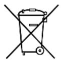
If you wish to finally dispose of the product, ask your local recycling centre or specialist dealer for details about how to do this in accordance with the applicable disposal regulations.
13 Technical data
13.1 Unit Data
| Marine Climate System MCS T6 | Marine Climate System MCS T12 | Marine Climate System MCS T16 | |
| Cooling power: 6000 BTU/h | 1758 W | 12000 BTU/h3517 W | 16000 BTU/h4689 W |
| Input voltage: 230 V 230 V 230 V | |||
| Current consumptionCooling: 3.7 A 4.3 A 5.5 A | |||
| Heating: | 4.7 A | 5.3 A | 6.9 A |
| Refrigerant: | R-410A | R-410A | R-410A |
| Refrigerant quantity: | 8.5 oz/241 g | 10.5 oz/298 g | 12.5 oz/354 g |
| CO2 equivalent: | 0.503 t | 0.622 t | 0.739 t |
| Global warming poten-tial (GWP): | 2088 2088 | 2088 | |
| Dimensions (W x H x D):Unit:Control panel:Control panel: | 448 x 282 x272 mm81 x 64 x 24 mm64 x 48 mm | 519 x 318 x315 mm81 x 64 x 24 mm64 x 48 mm | 544 x 341 x338 mm81 x 64 x 24 mm64 x 48 mm |
Contains fluorinated greenhouse gases
Hermetically sealed equipment
13.2 System Control Specifications
| Set point operating range: | 18.3 °C to 29.4 °C (65 °F to 85 °F) |
| Ambient temperature operating range displayed: | -15 °C to 65.6 °C (5 °F to 150 °F) |
| Sensor accuracy: | ±1.1 °C at 25 °C (± 2 °F at 77 °F) |
| Low voltage limit 230 V units: 175 V~ | |
| Low voltage processor reset: 50 V~ | |
| Line voltage: 230 V~ | |
| Frequency: 50 Hz | |
| Fan output (max.): 6 A at 230 V~ | |
| Valve output: 0.25 A at 230 V~ | |
| Heater output (max.): 20 A at 230 V~ | |
| Pump output: 1/2 HP at 230 V~ | |
| Compressor output: 2 HP at 230 V~ | |
| Minimum operating temperature: -17.8 °C (0 °F) | |
| Maximum ambient operating temperature: | 82.2 °C (180 °F) |
| Maximum Rh conditions: | 99 % Non Condensing |
| Display power consumption | < 5 W |
13.3 System Inputs
| Ambient or inside air temperature: | 1 |
| High pressure switch, HPF: | 1 |
| Low pressure switch, LPF(Not used in MCST): | 1 |
| Alternate inside air temperature sensor: | 1 |
| Outside air temperature sensor (optional): | 1 |
5 Description technique
Dometic Australia Pty. Ltd.
1 John Duncan Court
Varsity Lakes QLD 4227
1800 212121
+61 7 55076001
Mail: sales@dometic.com.au
AUSTRIA
Dometic Austria GmbH
Neudorferstraße 108
A-2353 Guntramsdorf
+43 2236 908070
+43 2236 90807060
Mail: info@dometic.at
BENELUX
Dometic Branch Office Belgium
Zincstraat 3
B-1500 Halle
+32 2 3598040
+32 2 3598050
Mail: info@dometic.be
BRAZIL
Dometic DO Brasil LTDA
Avenida Paulista 1754, conj. 111
SP 01310-920 Sao Paulo
+551132513352
+551132513362
Dometic Group Asia Pacific
Suites 2207-11 · 22/F · Tower 1
The Gateway · 25 Canton Road,
Tsim Sha Tsui · Kowloon
+852 2 4611386
+852 2 4665553
Mail: info@waeco.com.hk
HUNGARY
Dometic Zrt. Sales Office
Kerékgyártó u. 5.
H-1147 Budapest
+3614684400
+3614684401
Domettic Italy S.r.l.
Via Virgilio, 3
I-47122 Forli (FC)
+39 0543 754901
+390543754983
Mail: vendite@dometic.it
JAPAN
Dometic KK
Maekawa-Shibaura, Bldg. 2
2-13-9 Shibaura Minato-ku
Tokyo 108-0023
+81 3 5445 3333
品 +81354453339
Mail: info@dometic.jp
MEXICO
Circuito Médicos No. 6 Local 1
Colonia Ciudad Satélite
CP 53100 Naucalpan de Juárez
Estado de México
+52 55 5374 4108
+52 55 5393 4683
Mail: info@dometic.com.mx
NETHERLANDS
Dometic Benelux B.V.
Ecustraat 3
NL-4879 NP Etten-Leur
+31 76 5029000
+31 76 5029019
Mail: info@dometic.nl
NEW ZEALAND
Dometic New Zealand Ltd.
PO Box 12011
Penrose
Auckland 1642
+6496221490
+6496221573
Mail: customerservices@dometic.co.nz
NORWAY
Dometic Norway AS
∅sterøyveien 46
N-3232 Sandefjord
+47 33428450
+47 33428459
Mail: firmapost@dometic.no
POLAND
Dometic Poland Sp. z o.o.
Ul. Puławska 435A
PL-02-801 Warszawa
+48 22 414 3200
+48 22 414 3201
Mail: info@dometic.pl
PORTUGAL
Dometic Spain, S.L.
Komsomolskaya square 6-1
RU-107140 Moscow
+7 495 780 79 39
+7 495 916 56 53
Mail: info@dometic.ru
SINGAPORE
Dometic Pte Ltd
18 Boon Lay Way 06-140 Trade Hub 21
Singapore 609966
+65 6795 3177
+65 6862 6620
Mail: dometic@dometic.com.sg
SLOVAKIA
Dometic Slovakia s.r.o. Sales Office Bratislava
Nádražná 34/A
900 28 Ivánka pri Dunaji
/ +421 2 45 529 680
Mail: bratislava@dometic.com
SOUTH AFRICA
Dometic (Pty) Ltd.
Regional Office
South Africa & Sub-Saharan Africa
2 Avalon Road
West Lake View Ext 11
Modderfontein 1645
Johannesburg
+27114504978
+27114504976
Mail: info@dometic.co.za
SPAIN
Dometic Spain S.L.
Avda. Sierra del Guadarrama, 16
E-28691 Villanueva de la Cañada
Madrid
+34 91 833 60 89
+34 900 100 245
Mail: info@dometic.es
SWEDEN
Dometic Scandinavia AB
Gustaf Melins gata 7
Dometic Switzerland AG
Riedackerstrasse 7a
CH-8153 Rümlang
+41 44 8187171
+41 44 8187191
Mail: info@dometic.ch
UNITED ARAB EMIRATES
Dometic Middle East FZCO
P.O.Box17860
S-D 6, Jebel Ali Freezone
Dubai
+97148833858
+97148833868
Mail: info@dometic.ae
UNITED KINGDOM
Dometic UK Ltd.
Dometic House, The Brewery
Blandford St. Mary
Dorset DT119LS
+44 344 626 0133
+44 344 626 0143
Mail: customerservices@dometic.co.uk
USA
Dometic RV Division
1120 North Main Street
Elkhart, IN 46515
+1574-264-2131