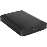
iVolt Xtra - Battery charger Thinkware - Free user manual and instructions
Find the device manual for free iVolt Xtra Thinkware in PDF.


User questions about iVolt Xtra Thinkware
0 question about this device. Answer the ones you know or ask your own.
Ask a new question about this device
Download the instructions for your Battery charger in PDF format for free! Find your manual iVolt Xtra - Thinkware and take your electronic device back in hand. On this page are published all the documents necessary for the use of your device. iVolt Xtra by Thinkware.
USER MANUAL iVolt Xtra Thinkware
Quick Start Guide & Warranty
This product is an external power supply, which is used to provide extended dash cam recording when the vehicle is parked, without depleting or damaging the vehicle's battery.
This manual outlines the basic steps required to install and use the external battery.
CONTENTS
English.... 3
Français.... 19
Deutsch 35
Quick Start Guide & Warranty
English
FCC
This device complies with part 15 of the FCC Rules.
Operation is subject to the following two conditions:
(1) This device may not cause harmful interference, and
(2) This device must accept any interference received, including interference that may cause undesired operation.
FCC Compliance Statement
Note : This equipment has been tested and found to comply with the limits for a Class A digital device, pursuant to part 15 of the FCC Rules. These limits are designed to provide reasonable protection against harmful interference in a residential installation. This equipment generates, uses and can radiate radio frequency energy and, if not installed and used in accordance with the instructions, may cause harmful interference to radio communications. However, there is no guarantee that interference will not occur in a particular installation. If this equipment does cause harmful interference to radio or television reception, which can be determined by turning the equipment off and on, the user is encouraged to try to correct the interference by one or more of the following measures:
- Reorient or relocate the receiving antenna.
- Increase the separation between the equipment and receiver.
- Connect the equipment to an outlet on a circuit different from that to which the receiver is connected.
- Consult the dealer or an experienced radio/TV technician for help.
- This appliance and its antenna must not be co-located or operation in conjunction with any other antenna or transmitter.
- A minimum separation distance of 20 cm must be maintained between the antenna and the person for this appliance to satisfy the RF exposure requirements.
Caution: Any changes or modifications to the equipment not expressly approved by the party responsible for compliance may void your permission to operate the equipment.
Note : This unit was tested with shielded cables on the peripheral devices.
Shielded cables must be used with the unit to insure compliance.
This Class A digital apparatus complies with Canadian ICES-003
Safety Information
Read and follow the safety information to safely use this product. If the instructions are not followed, the product's performance may degrade, or it may overheat, ignite, or explode and result in injury or property damage.

WARNING
Periodically inspect the product for proper operation. Incorrect wiring or aged and damaged cables may cause a fire.
- Stop using the product immediately and contact the customer service center if you smell smoke or strange odors coming from the product or the cables connected to the product.
- Stop using the product immediately and replace the product or cables if you see the product or its cables swelling or overheating.
- Store and use this product out of the reach of children or pets.

CAUTION
To avoid injury or damage to the product, follow these instructions when installing and using this product.
- Keep the product away from moisture and direct sunlight, and do not expose the product to physical impacts.
- Do not use this product for any purpose other than its intended use.
- Do not try to repair or modify the product. Unauthorized disassembly, repair, or modification of the product will void the product's warranty.
- Do not apply excessive pressure to the product or puncture the product with sharp objects.
- Do not place the product inside a microwave oven, or expose it to high pressure.
- Use only approved cables provided by the manufacturer when installing the product.
- Ensure that the product's contacts do not come into contact with conductive materials, such as metal.
- Do not use the product in an environment where the product's internal circuit may be affected by static or electromagnetic waves.
Included items
Open the package and ensure that the following items are included.
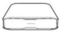
External battery

Charging cable

Output cables

Communication extension cable
Fuse holder (3 types)

Fuse (3 types)

Velcro tape

Quick start guide
Part names
Refer to the following figures for the location of connectors and indicators on the product.
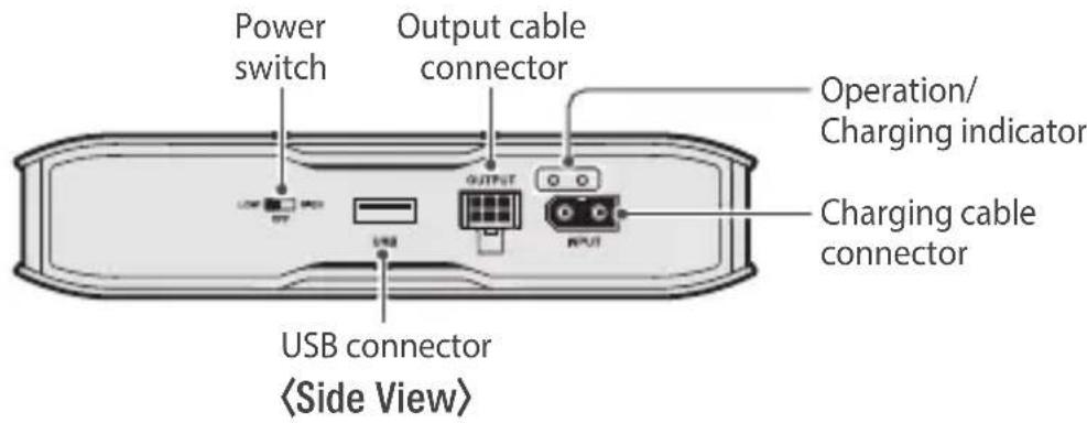
text_image
Power switch Output cable connector Operation/ Charging indicator USB connector 〈Side View〉 Charging cable connector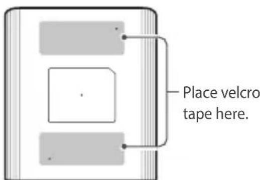
text_image
Place velcro tape here.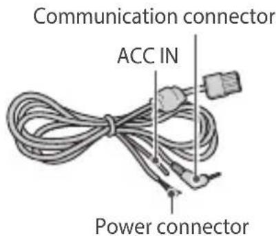
text_image
Communication connector ACC IN Power connectorOperation modes depending on the power switch settings
| Power switch setting Operation mode | |
 HIGH HIGH | Normal-speed charge ON (4.5 A) |
 HIGH HIGH | Power OFF |
 HIGH HIGH | High-speed charge ON (8.5 A) |

Caution - When setting the power switch
Set the power switch to HIGH (high-speed charge) when you use the charging cable for the fuse box. It will take more time to fully charge if the power switch is set to LOW (normal-speed charge).
Product features
- With its 8.5 A high-speed charging, the external battery is capable of operating a dash cam for up to 27 hours on approximately 50-minute charge (based on a power consumption rate of 3.5 Wh).
- The charge pump and constant voltage/current circuits integrated into the product are capable of fully charging and maintaining the external battery in optimal conditions (maintains over 80% capacity after 1,500 cycles).
- The MCU-controlled battery management system in the external battery safely and precisely controls the charge current and voltage, and the voltage balance between the battery cells.
- The thermal protection feature stops charging when the battery temperature reaches or exceeds 176°F (80°C). If the input terminal is connected wrongly, such as by connecting the continuous power (B+) and GND the other way, the device automatically stops battery output to protect itself.
- The device automatically stops battery output when short circuits are detected between the power terminals (B+, ACC) and the ground (GND). Charge the external battery to deactivate the protective feature if the protection mode persists.
- The device automatically stops battery output when the battery voltage drops below or reaches 11.5 V - 10.8 V.
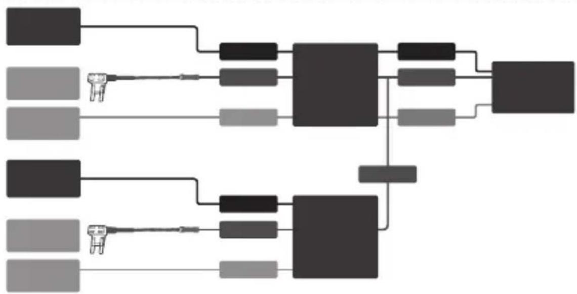
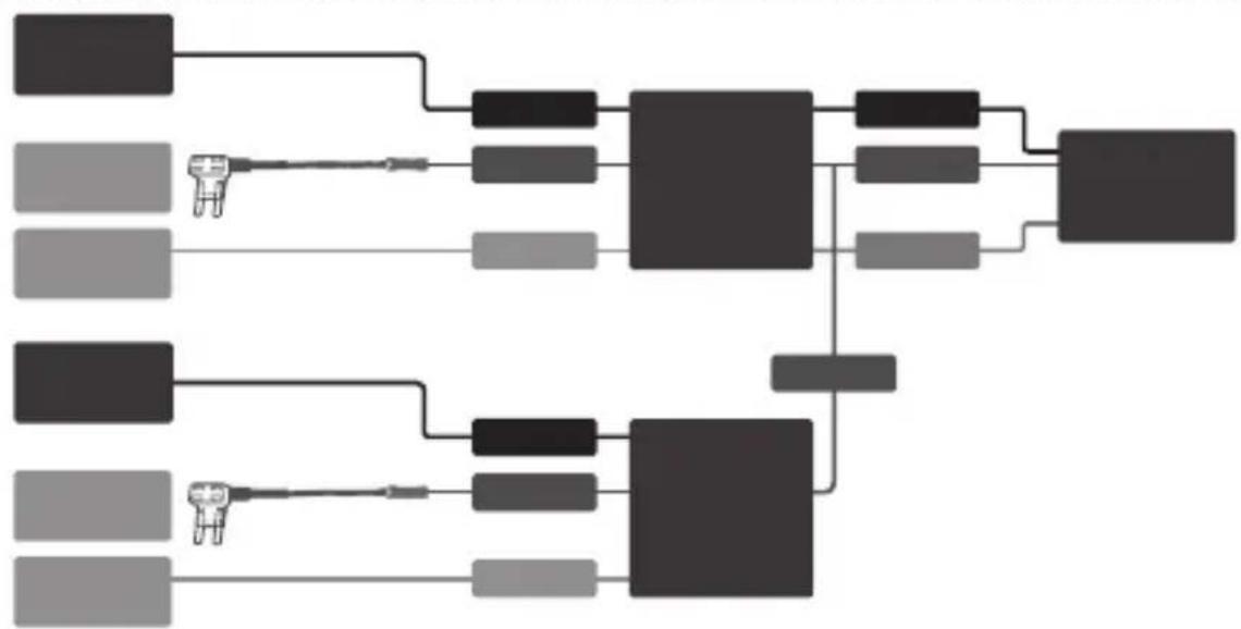
- Supports parallel installation of two external batteries to expand battery capacity. (Refer to "Wiring diagram" for details.)

Caution - Before installing the external battery
- The product warranty does not cover vehicle damage or product malfunctions caused by use of third-party cables, or by inappropriate installation conditions where the vehicle's alternator fails to generate sufficient charging voltage or current.
- In some vehicles, the vehicle's alternator may be overloaded and damaged by the increased current demand when you install two external batteries in parallel.
Installing the external battery
Refer to the following steps to correctly install and use the product.
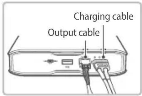
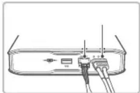
- With the product's power switch in the OFF position, connect the charging cable and output cable to the product's cable connectors.
text_image
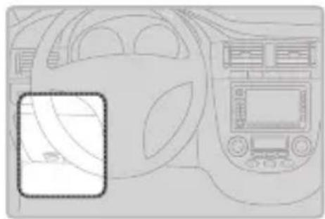
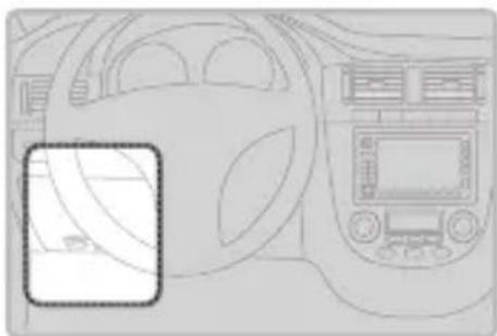
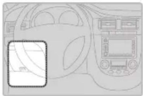
Charging cable Output cable- Open your vehicle's fuse box, check the fuse standard, and select the correct fuse holder between the included fuse holders.
natural_image
Interior view of a car dashboard and infotainment system (no visible text or symbols)
Note
The fuse box location in the vehicle may vary depending on the manufacturer and model of your vehicle. For more information, refer to your vehicle's manual.
-
In the fuse box, locate and remove the fuses for the continuous power (B+) and the accessory power supply.
-
The continuous power (B+) supply cable contacts supply power even when the engine is turned off. Select a continuous power supply cable that is less than 10 A.
- The accessory power (ACC) contacts supply power only when the engine is turned on.

natural_image
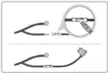
Illustration of a computer with two keys inserted into a grid, no text or symbols present- Insert the input cable's continuous power (B+) supply cable contact into the sleeve at the end of the fuse holder cable, and then secure it by squeezing on the sleeve using appropriate tools, such as pliers.
natural_image
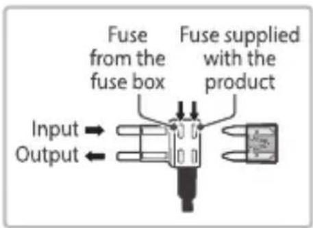
Two diagrams showing pliers and connectors with magnified detail (no text or symbols)- Install the fuse that was removed from the fuse box and the fuse supplied with the product into the fuse holder that is connected to the cable, and then install the fuse holder onto the continuous power supply contacts in the fuse box.
text_image
Fuse from the fuse box Fuse supplied with the product Input → Output ←
Note
- When connecting, be careful to not confuse it with the accessory power supply.
- If the fuse from the fuse box does not fit in the fuse holder, use other fuses that are supplied with the product.
- Check the output contacts in the fuse box with a tester, and ensure that the output contact is connected to the fuse holder's input contact.

Caution
- THINKWARE is not responsible for any problems and/or damages caused by unauthorized part modification, such as soldering fuses to cables, without using the fuse holders supplied with the product.
-
Ensure that the fuse holder is installed correctly for proper input and output connection. The fuse may blow if input and output connection is incorrect. THINKWARE is not responsible for any problems and/or damages to the vehicle due to an incorrect connection.
-
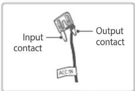
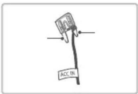
Peel off the sheath of the output cable and remove the cable from the vehicle. Then connect the output cable to a fuse leg of the ACC and reconnect the fuse to where ACC was in the fuse box.
text_image
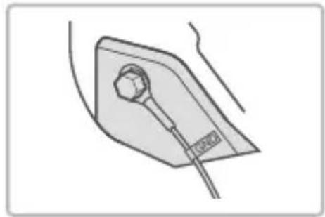
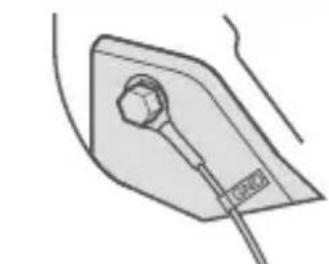
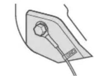
Input contact Output contact ACC IN- Find a bolt fixed on the vehicle's chassis, and connect the ground (GND) cable to the bolt.

Note
If the vehicle's bolt is coated, remove the coating before connecting the ground (GND) cable. The power may not be supplied correctly due to the coating.
natural_image
Simple line drawing of a medical or laboratory device with a bulb and connector (no text or symbols)Connecting the dash cam
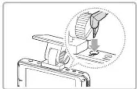
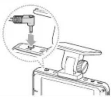
- Connect the communication connector of the output cable to the dash cam's BAT contact.

Note
Only dash cams that can communicate with the external battery can be connected.
natural_image
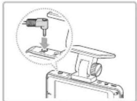
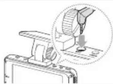
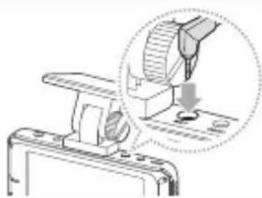
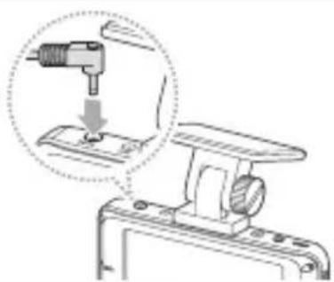
Diagram showing a mechanical assembly with a magnified inset of a tool interacting with a component (no text or symbols visible)- Connect the output cable's continuous power supply connection to the dash cam's continuous power cable and connect the power cable to the dash cam's DC-IN contact.

Note
Connect the B+ (yellow), GND (black), and ACC OUT (red) cables to the dash cam's B+, GND, and ACC cables respectively.
natural_image
Technical diagram of a mechanical device with a drill bit and base mount, showing a close-up view of the tool (no text or symbols present)- Secure the product to the driver's seat floor using the velcro tape provided with the product.
- Turn on the power, and ensure that the indicators are turned on for 3 seconds.
- Start the engine and check the indicators. Charging begins when the operation indicator fl ashes red for 10 seconds and remains solid.

Note
For more information, refer to "Indications for operation status" in the "Product specifications" section.
- Turn off the engine, and ensure that the dash cam switches to parking surveillance mode.

Note
In the dash cam's settings menu, disable the battery protection (low-voltage cutoff) feature by setting it to OFF, or set it to the lowest voltage available.
Wiring diagram
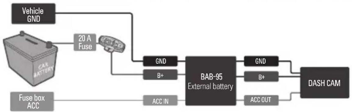
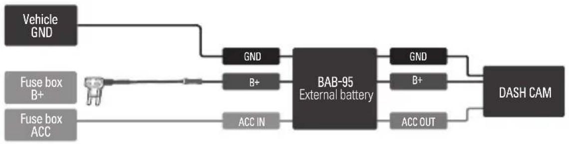
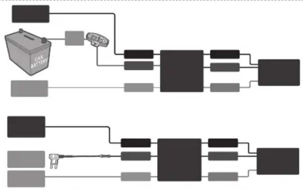
Refer to the following wiring diagrams to correctly connect the product.
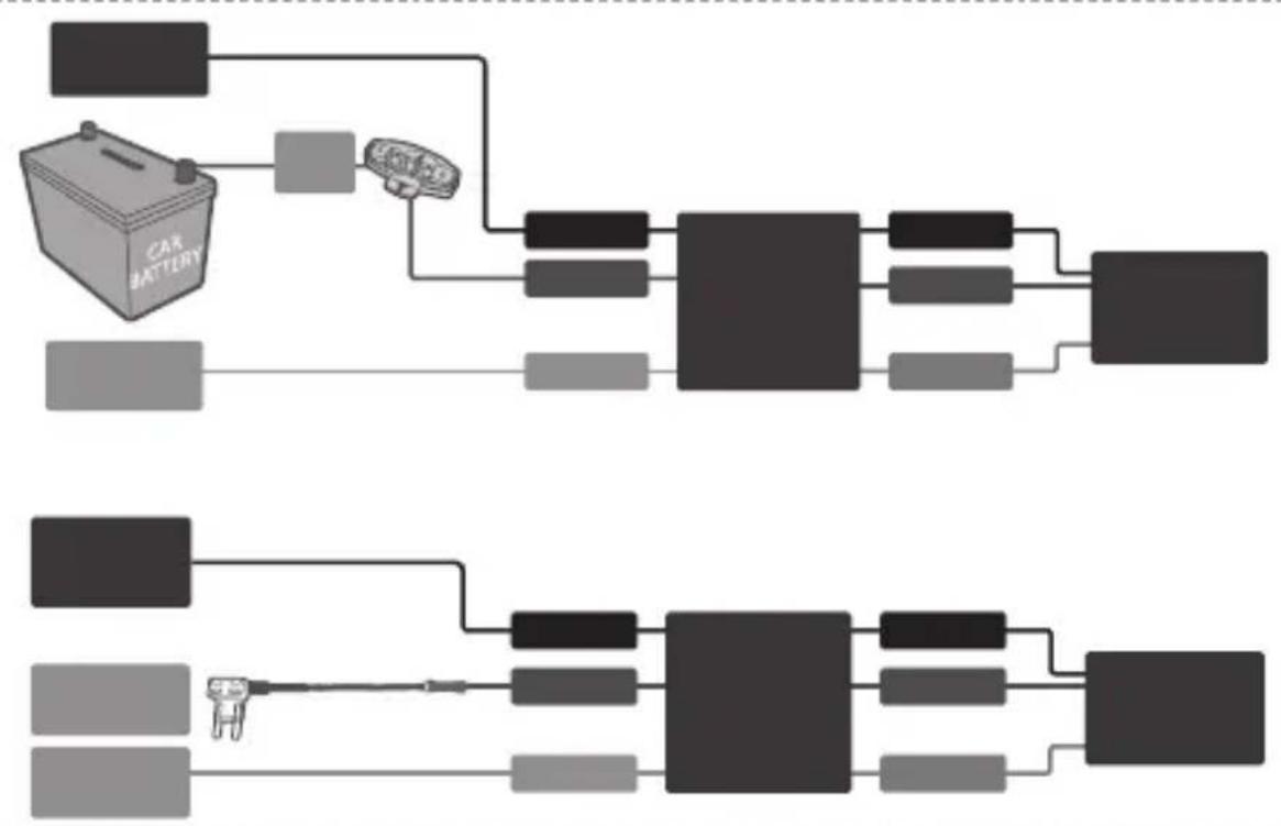
Suggested way to connect the product
flowchart
graph LR
    A["Vehicle GND"] --> B["20 A Fuse"]
    B --> C["GND"]
    C --> D["BAB-95 External battery"]
    D --> E["GND"]
    E --> F["DASH CAM"]
    G["Fuse box ACC"] --> H["ACC IN"]
    H --> I["External battery"]
    J["Car Battery"] --> B
    K["GND"] --> D
    L["B+"] --> D
    M["B+"] --> E
    N["ACC OUT"] --> I
When connecting the product directly to the vehicle, you should additionally buy a vehicle exclusive fuse that is 20 A - 30 A.
flowchart
graph LR
    A["Vehicle GND"] --> B["GND"]
    C["Fuse box B+"] --> D["B+"]
    E["Fuse box ACC"] --> F["ACC IN"]
    D --> G["BAB-95 External battery"]
    F --> G
    G --> H["GND"]
    H --> I["DASH CAM"]
    I --> J["B+"]
    J --> G
    G --> K["ACC OUT"]
When connecting two products in parallel
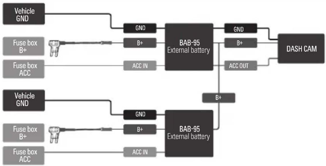
flowchart
graph LR
    A["Vehicle GND"] --> B["GND"]
    C["Fuse box B+"] --> D["B+"]
    E["Fuse box ACC"] --> F["ACC IN"]
    B --> G["BAB-95 External battery"]
    D --> G
    F --> G
    G --> H["GND"]
    G --> I["B+"]
    G --> J["ACC OUT"]
    H --> K["DASH CAM"]
    I --> K
    J --> K
    L["Vehicle GND"] --> M["GND"]
    N["Fuse box B+"] --> O["B+"]
    P["Fuse box ACC"] --> Q["ACC IN"]
    M --> R["BAB-95 External battery"]
    O --> R
    Q --> R
    R --> S["B+"]

Note
When charging a battery that is overly discharged or left unused for a long time, the black box will power on after reaching a stable output voltage using the trickle charging function, which gradually charges the battery to protect the battery cells. (It may take up to 5 minutes to supply power.)
Using the iVolt app via Bluetooth
If you connect the product with your smartphone, you can check the current battery's status, temperature, and charging status, as well as the number of impact detection (Motion Detection, Impact Detection, and Intelligent Impact Detection) on the iVolt app. To use the iVolt app, open the Play Store (for Android devices) or the App Store (for iOS devices) and download the iVolt app on your smartphone.
Connecting the iVolt app
Refer to the following steps to connect the iVolt app with your smartphone.

Note
- When connecting the product with your smartphone, make sure that Bluetooth on your smartphone is turned on and your smartphone is located within the allowable Bluetooth range of the product.
-
In some smartphones, the connection may be lost if the iVolt app is not used for a certain period of time, and the app may need to be reconnected.
-
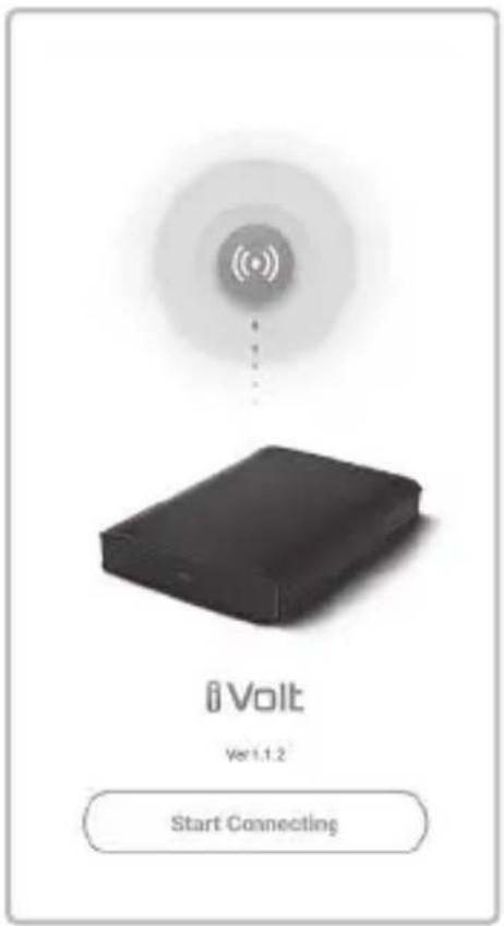
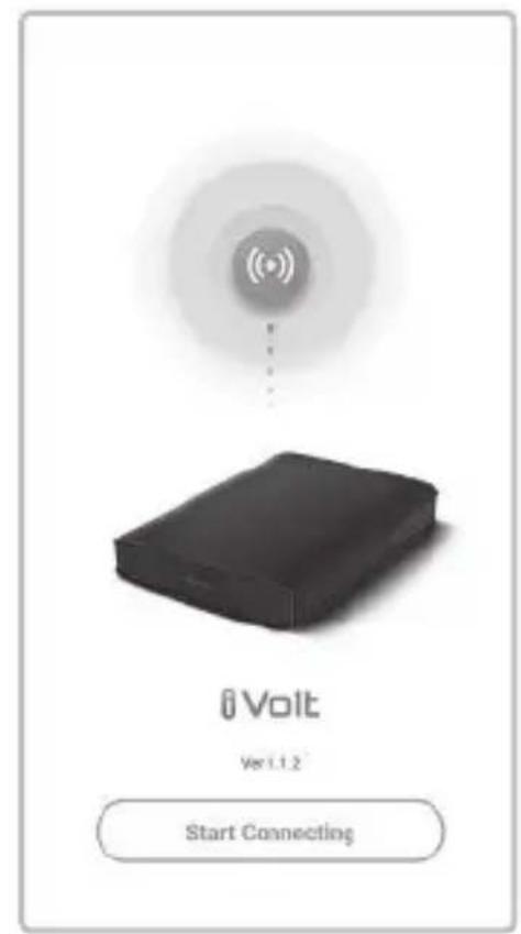
Open the iVolt app on your smartphone and tap Start Connecting.
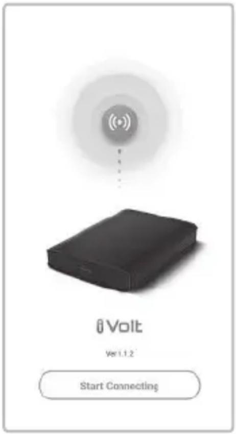
text_image
iVolt Ver 1.1.2 Start Connecting- On the Battery Connection list, tap the device to connect with.
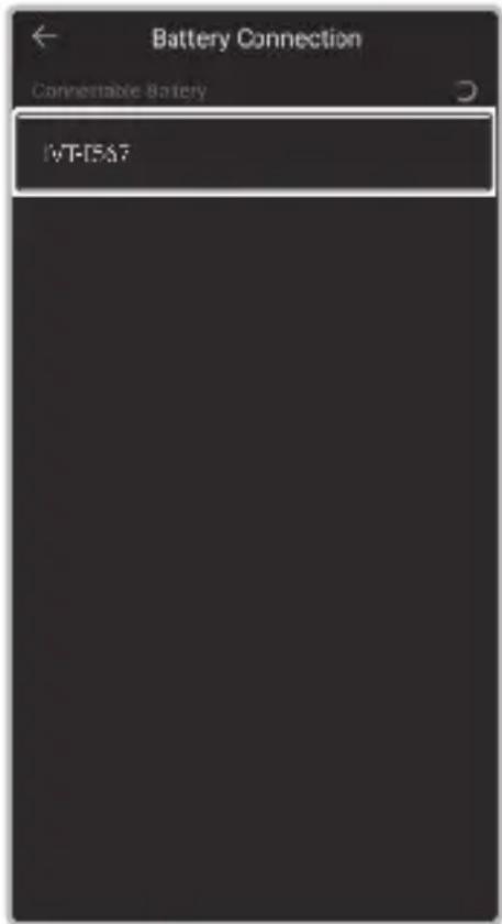
text_image
Battery Connection Convertible Battery I-VT-I-F5A7About the Home screen on the iVolt app
When you open the iVolt app and the product is successfully connected with your smartphone, you can check the current battery's status, temperature, and charging status, as well as the number of impact detection (Motion Detection, Impact Detection, and Intelligent Impact Detection) on the Home screen of the iVolt app.
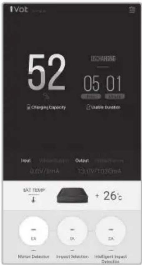
text_image
52 CHARGING 05 01 Charging Capacity Unable Duration Input Voltage Output 0.0V/10mA 13.0V/10Ω/10mA SAT TEMP + 26°C EA EA EA Motion Deflection Impact Deflection Intelligent Impact Selection
Note
If you open the iVolt app when the product is turned off, the remaining battery time displayed on the Home screen may differ from the actual battery status for about 10 minutes.
Product specifications
| Items Specifications | |
| Input voltage/current | · LOW (normal-speed charge mode): 12.0 V - 15.5 V/6.5 A MAX· HIGH (high-speed charge mode): 12.0 V - 15.5 V/13 A MAX |
| Output voltage/current | 11.0 V – 14.2 V/2 A MAX |
| Charging voltage/current | · LOW (normal-speed charge mode): 14.2 V/4.5 A Max· HIGH (high-speed charge mode): 14.2 V/8.5 A Max |
| Charging time | · LOW (normal-speed charge mode): Approximately 90 minutes· HIGH (high-speed charge mode): Approximately 50 minutes |
| Use time | Approximately 27 hours (based on a dash cam's 3.5 Wh power consumption rate) |
| Cells | Lithium iron phosphate (LiFePo4) |
| Product capacity | 12.8 V/7,500 mAh/96 Wh |
| Dimensions/weight | 155 (W) X 216 (L) X 34 (T) mm/Approximately 3.3 LB (1.5 Kg) |
| Operating temperature | · Charging: 0 - 45 °C· Discharging: -10 - 60 °C |
| Indications for operation status | |
| Powered on | Red and green indicators turn on simultaneously. |
| Pre-charging | Red indicator flashes. |
| Charging | Red indicator remains solid. |
| Fully charged | Green indicator remains solid. |
| Low input voltage | Red and green indicators flash simultaneously. |
| High internal temperature | Red and green indicators alternately flash. |
| Indications for Bluetooth connection | |
| In Parking Mode | Blue indicator flashes every 5 seconds. |
| Charging | |
| Fully charged | |
Battery disposal instructions
- Do not discard batteries.
- Do not incinerate batteries. Heat may cause battery explosion or a fire.
- Dispose of batteries according to local regulations.
Warranty
THINKWARE warrants to the original purchaser for the following period from your purchasing date against deficiencies in material and workmanship under normal use. Should this unit fail to operate in a satisfactory manner within the warranty period, THINKWARE will at its discretion, replace or repair the product. We may use functionally equivalent, similar (if model is discontinued or out of stock), reconditioned, refurbished, remanufactured, pre-owned or new products or parts.
External battery unit and all Accessories in Box:
1 Year
If service is required
Should this unit fail to operate in a satisfactory manner, it is best to first check with the store where it was originally purchased. Should this fail to resolve the matter and if you believe your unit meets the criteria for warranty replacement or repair, please contact us at www.thinkware.com/Support.
What this warranty does not cover
This limited warranty does not cover:
- If the device was not purchased from THINKWARE or its authorized retailers.
- Device malfunction due to the normal wear and tear, misuse, lack of maintenance, accidents, modification, alteration or repairs by an unauthorized person or entity.
- Products that are operated in combination with ancillary or peripheral equipment not furnished or otherwise certified by THINKWARE for use with the product or any damage to the products or ancillary equipment as a result of such uses.
- THINKWARE is not liable for any damages (properties, business, and/or indirect damages), loss or corruption of data for any reason, product damage or personal injuries that occur due to accidents or natural disasters.
♦ LIMITED WARRANTY AND DISCLAIMERS
THINKWARE warrants that the product will be free from defects in materials or workmanship under normal use for one (1) year starting from original date of purchase. You may be required to provide proof of purchase as a condition of receiving warranty service.
The obligations of THINKWARE and the right of the purchaser under this warranty is limited to repair or replacement at the option of THINKWARE authorized dealer. The purchaser must provide notice of any defect within (1) year from the date of purchase and the defective product must be returned to the store where it was originally purchased or THINKWARE authorized dealers, at your expense.
Where permitted by local law, THINKWARE Products and any replacement products or parts may be either new or refurbished to be functionally equivalent to new in performance and reliability. Replacement products or parts will have functionality at least equal to that of the product or part being replaced. Replacement products and parts are warranted to be free from defects in materials or workmanship for 90 days, or for the remainder of the warranty period for the THINKWARE Product which they are replacing or in which they are installed, whichever is longer.
This Limited Warranty extends only to the original retail or wholesale Buyer.
This Limited Warranty does not cover cosmetic damage or damage resulting from (a) accident, abuse, misuse, natural disaster, insufficient or excessive electrical supply, abnormal environmental conditions or other external causes; (b) repair, replacement, modification, unauthorized disassembly or service by anyone other than THINKWARE or THINKWARE authorized service provider; or (c) modification or conversion conducted at user's discretion, carelessness, or negligence.
EXCEPT AS EXPRESSLY SET FORTH IN THIS LIMITED WARRANTY, THERE ARE NO OTHER WARRANTIES, EXPRESS OR IMPLIED, FOR YOUR THINKWARE PRODUCT. ALL IMPLIED WARRANTIES OF MERCHANTABILITY OR FITNESS FOR A PARTICULAR PURPOSE IMPOSED BY LAW ARE LIMITED IN DURATION TO THE APPLICABLE WARRANTY PERIOD. THINKWARE DISCLAIMS ALL OTHER WARRANTIES INCLUDING ANY IMPLIED WARRANTIES.
This Limited Warranty gives you specific legal rights, and it is governed by the laws of the jurisdiction in which your THINKWARE Product was purchased. Some jurisdictions do not allow any limitation on how long a limited warranty will last or the exclusion or limitation of incidental or consequential damages in which case, the exclusions or limitations stated in this Limited Warranty may not apply to you. You may also have other rights that vary by jurisdiction.
To the extent allowed by local law, the remedies provided in this Limited Warranty are your sole and exclusive remedies. These terms and conditions supersede any prior agreements or representations, including statements made in sales literature or advice given in connection with your purchase.
TO THE EXTENT ALLOWED BY LOCAL LAW, AND EXCEPT AS SPECIFICALLY SET FORTH IN THIS LIMITED WARRANTY, IN NO EVENT SHALL THINKWARE OR ANY THINKWARE-AUTHORIZED SERVICE PROVIDER BE LIABLE FOR (1) ANY DAMAGES CAUSED BY THE PRODUCT OR THE FAILURE OF THE PRODUCT TO PERFORM, (2) ANY DAMAGES RESULTING FROM LOSS DATA, OR (3) ANY INCIDENTAL, CONSEQUENTIAL, CONTINGENT OR SPECIAL DAMAGES WHATSOEVER, (4) ANY OBLIGATIONS ARISING FROM TORT OR ANY OTHER LEGAL THEORY, AND WHETHER OR NOT ADVISED OF THE POSSIBILITY OF SUCH DAMAGES. THINKWARE MAKES NO OTHER WARRANTIES.
In the event of a product defect that requires support during the warranty period, please contact THINKWARE Customer Support (www.thinkware.com) for assistance.
natural_image
Interior view of a car dashboard and infotainment system (no visible text or symbols)
Remarque
natural_image
Illustration of a computer keyboard with two keys inserted, showing mode and frame (no text or symbols)natural_image
Two types of pliers with a magnified inset showing a close-up of the needle (no text or symbols)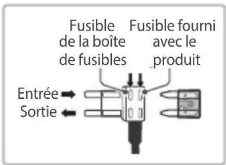
natural_image
Simple line drawing of a medical or surgical device with a tool inserted, no text or symbols presentnatural_image
Mechanical assembly diagram showing a clamping mechanism with a magnified inset (no text or symbols)natural_image
Technical diagram of a mechanical assembly with a drill bit and base mount (no text or symbols)text_image
Battery Connection Connectable Battery IWT567natural_image
Interior view of a car dashboard and infotainment system (no visible text or symbols)
Hinweis
natural_image
Illustration of a computer with two keys inserted into a rack (no text or symbols visible)natural_image
Two types of pliers with connectors, one magnified and one connected (no text or symbols)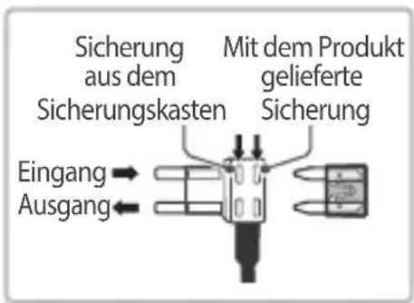
natural_image
Simple line drawing of a mechanical component with a knob and cable (no text or symbols)
Hinweis
natural_image
Diagram showing a mechanical assembly with an inset close-up of a tool interacting with a component (no text or symbols visible)
Hinweis
natural_image
Technical illustration of a mechanical assembly with a drill bit and base mount (no text or symbols)text_image
Battery Connection Connectable Battery IWT15A7natural_image
Coiled cable with connectors and a small component attached (no text or symbols visible)

natural_image
Diagram of a device with two cables connected to a central port (no text or symbols visible)
natural_image
Interior view of a car dashboard and infotainment system (no visible text or symbols)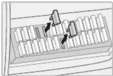
natural_image
Diagram of a mechanical assembly with two blocks and directional arrows indicating movement (no text or symbols)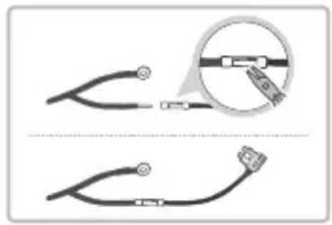
natural_image
Two types of stethoscope designs: one with magnified detail showing a cable being held, the other with a close-up view (no text or symbols)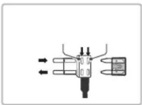
natural_image
Pure mechanical diagram showing a valve or actuator assembly with directional arrows indicating flow (no text or symbols)

text_image
ACC IN
natural_image
Simple line drawing of a mechanical component with a central knob and attached rod (no text or symbols)
natural_image
Technical illustration of a mechanical assembly with a magnified inset showing a component detail (no text or symbols)
natural_image
Diagram showing a mechanical device with a tool inserted into a base, and a magnified inset highlighting the component (no text or symbols present)

flowchart
graph TD
    A["Input Module 1"] --> B["User Icon"]
    C["Input Module 2"] --> D["User Icon"]
    E["Input Module 3"] --> F["User Icon"]
    G["Input Module 4"] --> H["User Icon"]
    I["Input Module 5"] --> J["User Icon"]
    K["Input Module 6"] --> L["User Icon"]
    M["Input Module 7"] --> N["User Icon"]
    O["Input Module 8"] --> P["User Icon"]
    Q["Input Module 9"] --> R["User Icon"]
    S["Input Module 10"] --> T["User Icon"]
    U["Input Module 11"] --> V["User Icon"]
    W["Input Module 12"] --> X["User Icon"]
    Y["Input Module 13"] --> Z["User Icon"]
    AA["Input Module 14"] --> AB["User Icon"]
    AC["Input Module 15"] --> AD["User Icon"]
    AE["Input Module 16"] --> AF["User Icon"]
    AG["Input Module 17"] --> AH["User Icon"]
    AI["Input Module 18"] --> AJ["User Icon"]
    AK["Input Module 19"] --> AL["User Icon"]
    AM["Input Module 20"] --> AN["User Icon"]


text_image
iVolt Ver 1.1.2 Start Connecting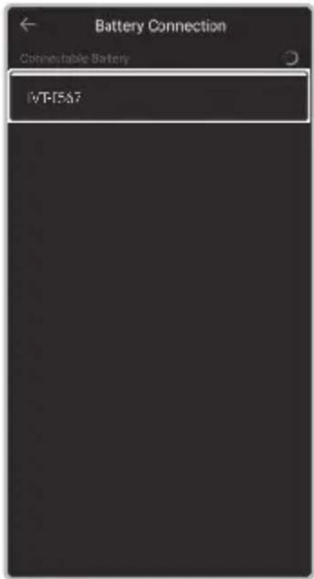
text_image
Battery Connection Connectable Battery IVT-IEA7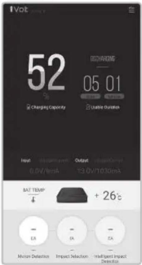
text_image
iVol 52 DCCHARGING 05 01 Charging Capacity Usable Detection Input Maximum Output Voltage 0.0V/1mA 13.0V/10.30mA BAT TEMP + 26°C - EA - EA - EA - Motion Detection Impact Detection Intelligent Impact Detection
| •• | |
| •• | |
| •• | |
| •• |




包装物品
打开包装并确认其中包含以下各项。



natural_image
Diagram of a device rear panel with two cables connected to ports (no text or symbols visible)
natural_image
Interior view of a car dashboard and infotainment system (no visible text or symbols)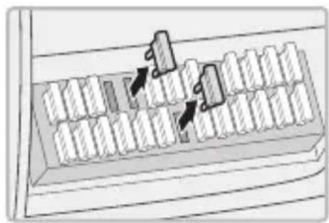
natural_image
Diagram of a mechanical device with two blocks and directional arrows indicating movement or force (no text or symbols)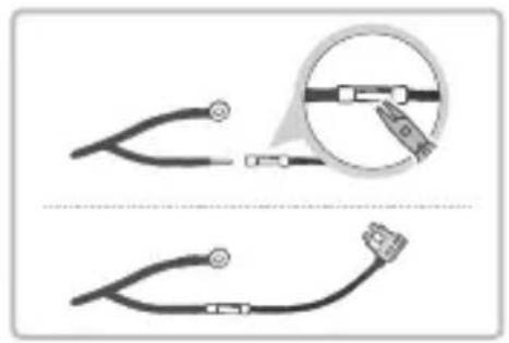
natural_image
Two types of stethoscope designs: one with magnified detail showing internal components, the other with a close-up view (no text or symbols)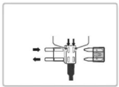
natural_image
Pure mechanical diagram showing a lever mechanism with arrows indicating direction (no text or symbols)
text_image
User interface element with a checklist icon and three bullet points, likely from an old user application.
text_image
Warning symbol with exclamation mark and three dots, likely indicating a warning or alert.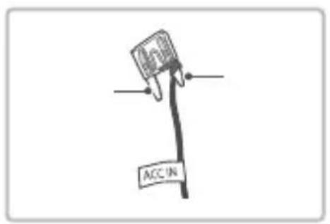
text_image
ACC IN
natural_image
Simple line drawing of a medical or laboratory device with a bulb and connector (no text or symbols)
natural_image
Technical illustration of a mechanical assembly with a magnified inset showing a gear mechanism (no text or symbols)
natural_image
Technical illustration of a mechanical assembly with a drill bit and workpiece (no text or symbols)

flowchart
graph TD
    A["Layer 1"] --> B["Component 1"]
    C["Layer 2"] --> D["Component 2"]
    E["Layer 3"] --> F["Component 3"]
    G["Layer 4"] --> H["Component 4"]
    I["Layer 5"] --> J["Component 5"]
    K["Layer 6"] --> L["Component 6"]
    M["Layer 7"] --> N["Component 7"]
    O["Layer 8"] --> P["Component 8"]
    Q["Layer 9"] --> R["Component 9"]
    S["Layer 10"] --> T["Component 10"]


text_image
Volt Ver 1.1.2 Start Connecting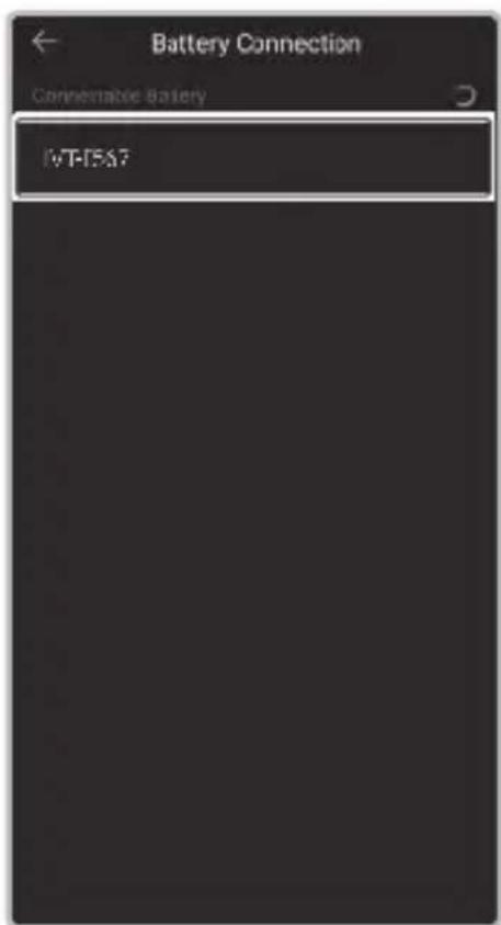
text_image
Battery Connection Connectable Battery IVT-TEST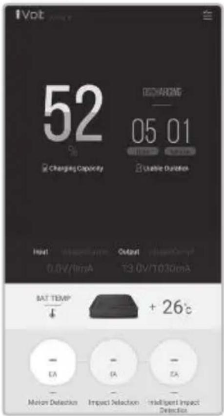
text_image
iVol 52 DCCHARGING 05 01 Charging Capacity Usable Detection Input Magnetic Output Voltage 0.0V/1mA 13.0V/10.30mA BAT TEMP + 26°C EA TA TA Motion Detection Impact Detection Intelligent Impact Detection
| ··· | |
| ··· | |
| ··· | |
| ··· |
| · | |
| · | |
| · |