1265 - Measuring equipment PeakTech - Free user manual and instructions
Find the device manual for free 1265 PeakTech in PDF.

| Product Type | Digital Storage Oscilloscope (DSO) |
| Brand | PeakTech |
| Model | 1265 |
| Bandwidth | 30 MHz |
| Number of Channels | 2 + 1 external trigger input |
| Real-time Sampling Rate | 125 MSa/s (dual channel), 250 MSa/s (single channel) |
| Record Length | 10 k points per channel |
| Vertical Sensitivity | 5 mV/div to 5 V/div |
| Time Base | 4 ns/div to 100 s/div (1-2-4 step) |
| Input Impedance | 1 MΩ ± 2% in parallel with 10 pF ± 5 pF |
| Display | 8-inch color TFT, 800 x 600 pixels |
| Power Supply | 100-240 VAC, 50/60 Hz, overvoltage category II |
| Power Consumption | < 15 W |
| Dimensions (L x H x D) | 348 mm x 170 mm x 78 mm |
| Weight | 1.5 kg |
| Interfaces | USB 2.0 (host and device), LAN, VGA |
| Main Functions | Autoscale, FFT, automatic measurements (Vpp, Vmax, etc.), cursors, Edge/Video/Slope/Pulse trigger, waveform record/playback, pass/fail output |
| Included Accessories | 2 passive probes 1:1/10:1, pass/fail adapter, CD (manual + software), USB cable, power cable |
| Maintenance and Cleaning | Clean with a soft, damp cloth (no solvents), disconnect before cleaning |
| Safety | CE compliant, overvoltage category II, pollution degree 2. Max input voltage 400 Vpp (DC + ACpp). Use only insulated probes for voltages > 42 V peak |
| Spare Parts and Repairability | Repairs reserved for qualified technician. Fuse 2 AT, 250 V user-replaceable. |
Frequently Asked Questions - 1265 PeakTech
User questions about 1265 PeakTech
0 question about this device. Answer the ones you know or ask your own.
Ask a new question about this device
Download the instructions for your Measuring equipment in PDF format for free! Find your manual 1265 - PeakTech and take your electronic device back in hand. On this page are published all the documents necessary for the use of your device. 1265 by PeakTech.
USER MANUAL 1265 PeakTech
text_image
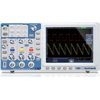
Lab equipment photo showing oscilloscope, multimeter, and electronic components with visible labels and waveform graphsPeakTech® I265/ I305/ I310
natural_image
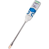
Diagram of a medical or electrical device with two components: a probe inserted into a screw and a tool inserted into a handle (no text or symbols present)natural_image
Line drawing of a soldering iron with a pointed tip and threaded end (no text or symbols)text_image
Coupling DC Inverted ON OFF Probe X10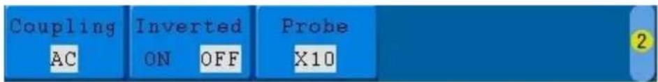
text_image
Coupling AC Inverted ON OFF Probe X10 2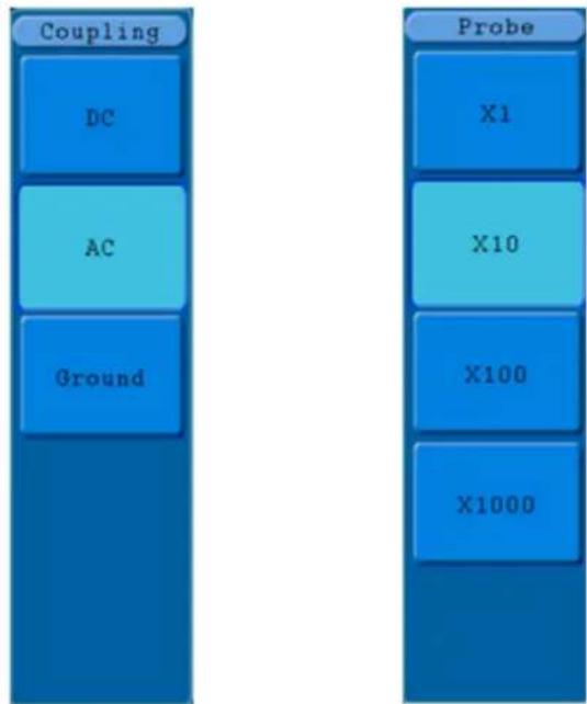
flowchart
graph TD
    A["Coupling"] --> B["DC"]
    A --> C["AC"]
    A --> D["Ground"]
    E["Probe"] --> F["X1"]
    E --> G["X10"]
    E --> H["X100"]
    E --> I["X1000"]
text_image
Main Set ZoomFig. 25 Menu Mode Heure
text_image
Single Pulse Source CH1 Couple DC When >24ns Auto &Holdofftext_image
ALT Pulse Source CH1 Couple DC When >24ns Auto &Holdofftext_image
Type Dots Vect Persist OFF XY Mode ON OFF Cymometer ON OFF VGA Disp ON OFFtext_image
MFunction Config Display Adjust Pass/fail Output LAN Set
text_image
Function Config Language English Set Time KeyLock AboutFig. 52 Menu de configuration
text_image
Function Adjust Self Cal DefaultFig.54 Menu Ajuster
Le menu Ajuster :
text_image
Auto 23.50ms Autocalibration Remove all probes cables from (CH1 CH2) Press (Auto calibration) for Calibration Press any key to quit.text_image
Function pass/fail Operate Output Rule SaveRuleFig.56 Menu Pass/Fail
Le menu Pass/Fail :
text_image
Function Output Typetext_image
Function LAN Set SetFig. 59 Menu LAN Set
Le menu LAN Set :
text_image
Internet Protocol (TCP/IP) Properties General You can get IP settings assigned automatically if your network supports this capability. Otherwise, you need to ask your network administrator for the appropriate IP settings. Obtain an IP address automatically Use the following IP address: IP address: 192 . 168 . 1 . 71 Subnet mask: 255 . 255 . 255 . 0 Default gateway: 192 . 168 . 1 . 1 Obtain DNS server address automatically Use the following DNS server addresses: Preferred DNS server: 192 . 168 . 1 . 1 Alternate DNS server: . Advanced... OK CancelFig. 60
text_image
Ports-settings Connect using LAN IP: 192.168.1.72 port: 3000 Custom USB Transfer Instructions (Some Types can choose to get bin / bmp or deep-memory data) WaveForm Image High Memory Depth Get Image File ".bmp" Setting: Keep Getting Delay(ms): 2000 Save data file automatically to below directory Browse... For there is a limit number of files in one single directory of Windows File System(FAT16, FAT32, NTFS), the number of files to be saved is not certain, it is recommended to choose a directory in NTFS disk drive, turn off the storage channels in device, and use short directory path to save more files. OK Get Data now! Keep Getting now!Fig. 61
text_image
Internet Protocol (TCP/IP) Properties General You can get IP settings assigned automatically if your network supports this capability. Otherwise, you need to ask your network administrator for the appropriate IP settings. ○ Obtain an IP address automatically ● Use the following IP address: IP address: 192 . 168 . 1 . 71 Subnet mask: 255 . 255 . 255 . 0 Default gateway: 192 . 168 . 1 . 1 ○ Obtain DNS server address automatically ● Use the following DNS server addresses: Preferred DNS server: 192 . 168 . 1 . 1 Alternate DNS server: . Advanced... OK CancelFig. 63
text_image
Ports-settings Connect using LAN IP: 192.168.1.72 port: 3000 Custom USB Transfer Instructions (Some Types can choose to get bin / bmp or deep-memory data) WaveForm Image High Memory Depth Get Image File ".bmp" Setting: Keep Getting Delay(ms): 2000 Save data file automatically to below directory Browse... For there is a limit number of files in one single directory of Windows File System (FAT16, FAT32, NTFS), the number of files to be saved is not certain, it is recommended to choose a directory in NTFS disk drive, turn off the storage channels in device, and use short directory path to save more files. OK Get Data now! Keep Getting now!Fig. 64
text_image
Overshoot Vmax Vpp Vtop Vamp Vbase Vmin PreshootFig. 68
text_image
AutoScale ON OFF Mode Wave ModeFig. 76 Menu Autoscale
Avis :
Le menu Autoscale :
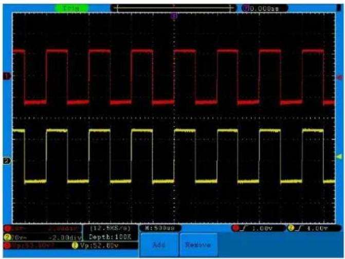
line
| Time (s) | Red Wave (dB) | Yellow Wave (dB) | |----------|---------------|------------------| | 1.56 | 1.56 | -2.0 | | 2.0 | 2.0 | -2.5 | | 3.5 | 3.5 | -3.5 | | 5.0 | 5.0 | -4.5 | | 6.5 | 6.5 | -5.5 | | 8.0 | 8.0 | -6.5 | | 9.5 | 9.5 | -7.5 | | 11.0 | 11.0 | -8.5 | | 12.5 | 12.5 | -9.5 | | 14.0 | 14.0 | -10.5 | | 15.5 | 15.5 | -11.5 | | 17.0 | 17.0 | -12.5 | | 18.5 | 18.5 | -13.5 | | 20.0 | 20.0 | -14.5 | | 21.5 | 21.5 | -15.5 | | 23.0 | 23.0 | -16.5 | | 24.5 | 24.5 | -17.5 | | 26.0 | 26.0 | -18.5 | | 27.5 | 27.5 | -19.5 | | 29.0 | 29.0 | -20.5 | | 30.5 | 30.5 | -21.5 | | 32.0 | 32.0 | -22.5 | | 33.5 | 33.5 | -23.5 | | 35.0 | 35.0 | -24.5 | | 36.5 | 36.5 | -25.5 | | 38.0 | 38.0 | -26.5 | | 39.5 | 39.5 | -27.5 | | 41.0 | 41.0 | -28.5 | | 42.5 | 42.5 | -29.5 | | 44.0 | 44.0 | -30.5 | | 45.5 | 45.5 | -31.5 | | 47.0 | 47.0 | -32.5 | | 48.5 | 48.5 | -33.5 | | 50.0 | 50.0 | -34.5 | | 51.5 | 51.5 | -35.5 | | 53.0 | 53.0 | -36.5 | | 54.5 | 54.5 | -37.5 | | 56.0 | 56.0 | -38.5 | | 57.5 | 57.5 | -39.5 | | 59.0 | 59.0 | -40.5 | | 60.5 | 60.5 | -41.5 | | 62.0 | 62.0 | -42.5 | | 63.5 | 63.5 | -43.5 | | 65.0 | 65.0 | -44.5 | | 66.5 | 66.5 | -45.5 | | 68.0 | 68.0 | -46.5 | | 69.5 | 69.5 | -47.5 | | 71.0 | 71.0 | -48.5 | | 72.5 | 72.5 | -49.5 | | 74.0 | 74.0 | -50.5 | | 75.5 | 75.5 | -51.5 | | 77.0 | 77.0 | -52.5 | | 78.5 | 78.5 | -53.5 | | 80.0 | 80.0 | -54.5 | | 81.5 | 81.5 | -55.5 | | 83.0 | 83.0 | -56.5 | | 84.5 | 84.5 | -57.5 | | 86.0 | 86.0 | -58.5 | | 87.5 | 87.5 | -59.5 | | 89.0 | 89.0 | -60.5 | | 90.5 | 90.5 | -61.5 | | 92.0 | 92.0 | -62.5 | | 93.5 | 93.5 | -63.5 | | 95 | 95 | -64 | | 96 | 96 | -64 | | 97 | 97 | -64 | | 98 | 98 | -64 | | 99 | 99 | -64 | | 1 | 1 | -64 | The chart displays two waveforms (red and yellow) plotted against time (x-axis) and voltage (y-axis). The red line represents a square wave with amplitude in dB, the yellow line represents a square wave with amplitude in V, and the orange line represents an orange scale (ON/OFF) for the mode of the wave axis (Mode). The wave axis is labeled as 'OFF'. The x-axis is labeled 'Time' and the y-axis is labeled 'Value'. The data is measured at three different times (in seconds) and scaled by a factor of approximately four times (in dB).Gain (db) = 20Xlog (gain)