2608C - Measuring equipment Weidmüller - Free user manual and instructions
Find the device manual for free 2608C Weidmüller in PDF.


User questions about 2608C Weidmüller
0 question about this device. Answer the ones you know or ask your own.
Ask a new question about this device
Download the instructions for your Measuring equipment in PDF format for free! Find your manual 2608C - Weidmüller and take your electronic device back in hand. On this page are published all the documents necessary for the use of your device. 2608C by Weidmüller.
USER MANUAL 2608C Weidmüller
text_image
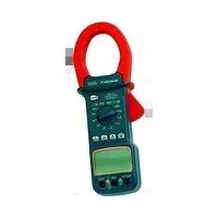
Technical line drawing of a digital clamp meter with labeled ports and function dialde Digitales Zangemessgerät, Bedienungsanleitung....3
en Digital clamp meter, Operating instructions....19
fr Multimètre à pince numérique, Mode d'emploi....36
it Pinza amperometrica digitale, Istruzioni di funzionamento.....53
es Multímetro digital con pinza, Manual de instrucciones......70
hu Digitális szorításmérő, Üzemel tetési útmutató....87
Weidmüller

INHALTSVERZEICHNIS
EINFÜHRUNG 3
Lieferumfang 3
| Bereich | Auflösung | Genauigkeit |
| 6,6nF | 1PF | ± (Messw. 3,0 % + 30 d) |
| 66nF | 10PF | ± (Messw. 3,0 % + 10 d) |
| 660nF | 100PF | ± (Messw. 3,0 % + 30 d) |
| 6,6μF | 1nF | ± (Messw. 3,0 % + 10 d) |
| 66μF | 10nF | ± (Messw. 3,0 % + 10 d) |
| 660μF | 100nF | ± (Messw. 3,0 % + 10 d) |
| 6,6mF | 1μF | ± (Messw. 5,0 % + 10 d) |
SAFETY INFORMATION 3
Standards 5
INSTRUMENT LAYOUT 6
HOW TO MAKE MEASUREMENTS 9
Voltage measurements 9
Current measurements 10
Resistance measurements 11
Continuity measurements 11
Diode tests 11
Capacitance measurements 12
Frequency measurements 12
% Duty cycle measurements 12
SPECIFICATIONS 13
MAINTENANCE 18
Cleaning 18
Replacing the battery 18
19
9427370000 00/06.2019
INTRODUCTION
This manual contains information and warnings which must be followed to ensure safe operation and retain the meter in safe condition.
READ "SAFETY INFORMATION" BEFORE USING THE METER.
This clamp meter is a handheld 6600-count instrument that is designed for use in the laboratory, field servicing, at home, and any circumstance where high current measurement is required. The clamp meter is built with a design of finger guard which ensures users operating the instrument under a safety situation; a rugged case that is shock resistant and fire-retardant; and electronic overload protection for all functions and ranges. In addition, a carrying case (optional accessory) is available for easy portability of the meter and avoiding damage.
Scope of delivery
- Digital Clamp Meter (DCM)
- Test lead set (one black, one red)
- 9-V battery (installed in the meter)
- Operating instructions
If any of the above items are missing or are received in a damaged condition, please contact the distributor from whom you purchased the unit.
SAFETY INFORMATION
The following safety precautions must be observed to ensure maximum personal safety during the operation, service and repair of this meter:
20
9427370000 00/06.2019
- Read these operating instructions thoroughly and completely before operating your meter. Pay particular attention to WARNINGS which will inform you of potentially dangerous procedures. The instructions in these warnings must be followed.
- Always inspect your meter, test leads and accessories for any sign of damage or abnormality before every use. If any abnormal conditions exist (eg-broken test leads, cracked cases, display not reading, etc.), do not attempt to take any measurements.
- Do not expose the instrument to direct sun light, extreme temperature or moisture.
- Never ground yourself when taking electrical measurements. Do not touch exposed metal pipes, outlets, fixtures, etc., which might be at ground potential. Keep your body isolated from ground by using dry clothing, rubber shoes, rubber mats, or any approved insulating material.
- To avoid electric shock use CAUTION when working with voltages above 40 Vdc or 20 Vac. Such voltages pose a shock hazard.
- Never exceed the maximum allowable input value of any function when taking a measurement. Refer to the specifications for maxi-mum inputs.
- Never touch exposed wiring, connections or any live circuit when attempting to take measurements.
- Do not attempt to operate this instrument in an explosive atmosphere (i.e. in the presence of flammable gases or fumes, vapor or dust).
- When testing for the presence of voltage, make sure the voltage function is operating properly by reading a known voltage in that function before assuming that a zero reading indicates a no-voltage condition. Always test your meter before and after taking measurements on a known live circuit.
- Calibration and repair of any instrument should only be performed by qualified and trained service technicians.
- D o not attempt calibration or service unless trained and another person capable of rendering first aid and resuscitation is present.
■ Remember: Think Safety, Act Safely.
Standards
Conforms to IEC 61010-1 (EN 61010-1), IEC 61010-2-032
(EN 61010-2-032), CAT III 1000V, CAT IV 600V, Class II, Pollution
degree 2, Indoor use.
CAT III: Is for measurements performed in the building installation.
CAT IV: Is for measurements performed at the source of the low-voltage installation.
EMC: Conforms to EN 61326-1: 2006
CE
Compliant with the relevant EU directives
The symbols used on this instrument are:
Dangerous voltage.
Caution, refer to accompanying documents
☐ Equipment protected throughout by Double insulation (Class II)
\~ Alternating current
--- Direct current
Ground
22
9427370000 00/06.2019
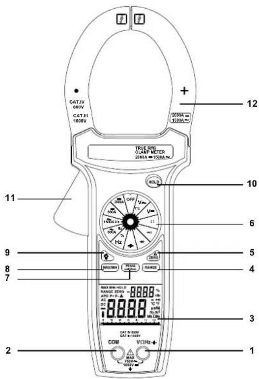
INSTRUMENT LAYOUT
text_image
CAT.IV 600V CAT.III 1000V 2000A = 1500A + 12 TRUE RMS CLARP METER 2000A = 1500A HOLD 11 OFF V Hz V Ω 1500A HZ 100A Hz RANGE MAX/MIN=HOLD RANGE=ZERO APO P= P-▲ DC 8.888 mA dB N/A DM CAT IV 600V CAT III 1000V COM VCHz MAX 750VA- 1500V 1 2 3 4 5 6 1023
9427370000 00/06.2019
2608C.p65
23
2009/6/5, 下午 04:18
1. VΩHz% +←→, Voltage, Ohms, Frequency, Duty cycle, Capacitance, Diode Input Terminal
This is the positive input terminal for Voltage, Ohms, Frequency, Duty cycle, Capacitance, Diode measurements. Connection is made to it using the red test lead.
2. COM Common Terminal
This is the negative (ground) input terminal for all measurement modes except current. Connection is made to it using the black test lead.
3. D isplay
The display indicates the measured value of a signal, function mode, and annunciator.
4. RANGE Button
The meter also has a manual range mode. In manual range, you select and lock the meter in a range. To manually select a range: Press [RANGE] button to hold the selected range. Subsequently pressing the [RANGE] button will select each range in sequence from the lowest to highest range. Hold the button for 2 seconds to return to the Autorange Mode.
5. ZERO Button
On the DC current ranges, the /ZERO button works as the zero mode, and on other functions, the /ZERO button works as the relative mode. Press REL button again to exit the mode. Press ZERO button for more than 2 seconds to exit.
In the Relative mode, the value shown on the LCD is always the difference between the stored reference value and the present reading. For example, if the reference value is 24.00V and the present reading is 12.50V, the display will indicate -11.50V. If the new reading is the same as the reference value, the display will be zero.
6. F unction/Range selector rotary switch
This rotary switch selects the fuction, and selects the desired range.
7. PE AK ± Button
- Record the peak+ or peak- value in a measurement. It is usable with AC voltage, AC current measurements. If the pressed time >2 sec, the PEAK function will enter to calibration mode, the LCD will show "CAL" and the internal buffer will remember the internal op off set voltage then back to the measure mode.
- Response time: more than 1ms. 3. The recorded value of PEAK function will show on the sub-display, and the value being measured will show on the main-display.
8. MAX / MIN Button
The "MAX" displays the maximum value of measurements. The "MIN" displays the minimum value of measurements. press MAX/MIN button for more than 2 seconds to exit. The recorded value of MAX/MIN function will show on the sub-display, and the value being measured will show on the main-display.
9. 🙏 Backlight Button
Press the ⚙ button to activate the backlight for approximately 60 second.
10.HOLD Button
Press [HOLD] button to toggle in and out of the Data Hold mode. In the data hold mode, the "HOLD" annunciator is displayed and the last reading is held on the display. Press [HOLD] button again to release the hold and current readings are once again displayed.
11. Trigger
Press the lever to open the transformer. When the lever is released, the jaws will close again.
12. Transformer jaws
Pick up the AC or DC current flowing through the conductor. The "+" marking on the jaw indicates direction of DC current existing on the conductor being tested which follows forward and vertically with jaws, and reading shown on display is positive.
25
9427370000 00/06.2019
13. Other Functions
Auto Power off
- Auto power off: approx. 30 minutes.
- After auto power off, press any button to restart the meter, and the reading of measurement will be maintained in the display.
Cancellation Of Auto Power Off Feature:
Press and hold the (RANGE) button while rotating function switch from off to any position to turn the meter on. The auto power off feature is disabled.
Noto "APO" annunciator is missing from the LCD.
HOW TO MAKE MEASUREMENTS
Before making any measurements read safety precautions. Always examine the instrument and accessories used with the instrument for damage, contamination (excessive dirt, grease, etc.) and defects. Examine the test leads for cracked or frayed insulation and make sure the lead plugs fit snugly into the instrument terminals. If any abnormal conditions exist, do not attempt to make any measurements.
Voltage measurements
- Turn off power to the device under test and discharge all capacitors.
- Plug the black test lead into the COM input jack on the meter and connect the test lead tip to a grounded point (the reference point for measurement of voltage).
- Set the Function/Range switch to the "V\~ / V==" position.
WARNING
To avoid possible electric shock, instrument damage and / or equipment damage, do not attempt to take any voltage measurements if the voltage is above 1000Vdc / 750Vac. 1000Vdc and 750Vac are the maximum voltages that this instrument is designed to measure.
- Plug the red test lead into the VΩ input jack on the meter and connect the circuit where a voltage measurement is required. Voltage is always measured in parallel across a test point.
- Turn on power the circuit /device to be measured and make the voltage measurement reduce the range setting if set too high until a satisfactory reading is obtained.
- After completing the measurement, turn off power to the circuit / device under test, discharge all capacitors and disconnect the meter test leads.
Current measurements
WARNING
These Snap-Arounds are designed to take current measurements on circuits with a maximum voltage difference of 1000VAC between any conductor and ground potential. Using the Snap-Around for current measurements on circuits above this voltage may cause electric shock, instrument damage and/or damage to the equipment under test. Before measuring current make certain that the test leads are removed from the instrument.
Do not take current readings on circuits where the maximum current potential is not known. Do not exceed the maximum current that this instrument is designed to measure.
- Set the Function/Range switch to the A=/A\~ position.
- Press the trigger to open the transformer jaws and clamp them around a conductor. Jaws should be completely closed before taking a reading.
- The most accurate reading will be obtained by keeping the conductor across center of the transformer jaws.
- The reading will be indicated on the display.
- Reduce the range setting if set too high until a satisfactory be st resolution reading is obtained.
Resistance measurements
- Set the Function/Range switch to the "Ω" position.
- Turn off power to the circuit under test. External Voltage across the components causes invalid reading.
- Connect the red test lead to the "VΩ" jack and the black test lead to the "COM" jack.
- Connect the test leads to the points of measurements and read the value from the display.
Continuity measurements
- Set the Funtion switch to the "◆" position.
- Turn off power to the circuit under test. External Voltage across the components causes invalid reading.
- Connect the test leads to the two points at which continuity is to be tested. The buzzer will sound if the resistance is less than approximately 30 .
Diode tests
- Set the Function/Range switch to the "→" position.
- Turn off power to the circuit under test. External voltage across the components causes invalid readings.
- Connect the red test lead to the "VΩ" jack and the black test lead to the "COM" jack.
- Touch probes to the diode. A forward-voltage drop is about 0.6V (typical for a silicon diode).
- Reverse probes. If the diode is good, "OL" is displayed. If the diode is shorted, "0.00" or another number is displayed.
- If the diode is open, "OL" is displayed in both directions.
- Audible Indication: Less than 0.03V.
28
9427370000 00/06.2019
Capacitance measurements
- Set the Function/Range switch to the "-+-" position.
- Connect the red test Idad to the "VΩ" jack and the black test lead to the "COM" jack.
- Touch the probes to the capacitor. Observe polarity when measuring polarized capacitors.
- Read the capacitance directly from the display.
- Discharge the capacitor before taking capacitance measurements.
- The meter has a residual capacitance in the 6.6nF and 660nF ranges, which is a normal status. Before taking measurements, press the Relative D button to zero the residual capacitance.
- When the capacitor to be tested is connected, if "dIS.C" symbol indicate on LCD, it means there is voltage existing in the tested capacitor and to be discharged before testing.
Frequency measurements
- Set the Function/Range switch to the "Hz/%" position.
- Connect the red test lead to the "VΩ" jack and the black test lead to the "COM" jack.
- Connect the test leads to the point of measurement and read the frequency from the display.
%Duty cycle measurements
- Set the Function/Range switch to the "Hz/%" position.
- Connect the red test lead to the "VΩ" jack and the black test lead to the "COM" jack.
- The readings of % DUTY CYCLE measurements will show on the sub-display.
29
9427370000 00/06.2019
2608C.p65
29
2009/6/5, 下午 04:18
SPECIFICATIONS
- Display: 6600 counts, 66 segments analog bar-graph.
- Polarity: Automatic, (-) negative polarity indication.
- OverrangeIndication:(OL)or(-OL)lsdisplayed.
- LowBatteryIndication:The " " is displayed when the battery voltage drops below accurate operating level.
- MeasurementRate:2.8/sec, nominal. 28/sec, Analog bar-graph.
- Operating Environment: 0°C to 50°C at < 70% R.H.
- Storage Environment: -20°C to 60°C at < 80% R.H.
- TemperatureCoefficient: 0.1 × (specified accuracy) / ^ (< 18^ or > 28^) .
- AutoPowerOff:30 minutes after rotary switch or mode changes.
- Altitude:6561.7 Feet (2000m)
- Power: Standard 9-volt battery, NEDA 1604, IEC 6F22, JIS 006P.
- BatteryLife:75 hours typical with carbon-zine battery.
- Jaw Opening Capability: 57mm conductor, 70 × 18mm bus bar.
- Size (H × W × D): 11.1 × 4.3 × 2.1 inches (281 × 108 × 53 mm).
- Weight: Approx. 20.1 OZ/570g grams (including battery)
Accuracy is given as ±(% of reading ]+[number of least significant digits] at 18°C to 28°C, with relative humidity up to 70%.
9427370000_00/06.2019
DC Volts
| Range | Resolution | Accuracy | Input Impedance |
| 660mV | 0.1mV | ± (0.5% rdg + 2d) | >100MΩ |
| 6.6V | 1mV | ± (0.5% rdg + 2d) | 10MΩ |
| 66V | 10mV | ± (0.5% rdg + 2d) | 9.1MΩ |
| 660V | 100mV | ± (0.5% rdg + 2d) | 9.1MΩ |
| 1000V | 1V | ± (0.5% rdg + 2d) | 9.1MΩ |
Overload protection: 1000V DC or 750V AC rms
AC Volts (True RMS)
| Range | Resolution | Accuracy (50~500Hz) | Input Impedance |
| 660mV | 0.1mV | ± (1.5% rdg + 8d) 50~100Hz | >100MΩ |
| 6.6V | 1mV | ± (1.5% rdg + 8d) 50~500Hz | 10MΩ |
| 66V | 10mV | ± (1.5% rdg + 8d) 50~500Hz | 9.1MΩ |
| 660V | 100mV | ± (1.5% rdg + 8d) 50~500Hz | 9.1MΩ |
| 750V | 1V | ± (1.5% rdg + 8d) 50~500Hz | 9.1MΩ |
Crest Factor: ≤3
Peak Hold: ±(3.0% rdg + 200 dgts) on 66V to 750V ranges
AC coupled true rms specified from 5% to 100% of range
FREQUENCY Ranges: 50Hz \~ 1kHz.
Accuracy: ± (0.1% rdg + 5 dgts)
Minimum Input voltage Range: >500dgts.
The readings of frequency measurements will show on the sub-display.
Overload protection: 1000V DC or 750V AC rms
AC current (True RMS)
| Range | Resolution | Accuracy (50 ~ 400Hz) |
| 660A | 0.1A | 0~660A±(2.0% rdg+10d)50~60Hz |
| 0~660A±(3.0% rdg+10d)61~400Hz | ||
| 1500A | 1A | 660~1000A±(2.5% rdg+10d)50~60Hz |
| 660~1000A±(3.5% rdg+10d)61~400Hz | ||
| 1000~1500A±(5.0% rdg+10d)50~400Hz |
Crest Factor: ≤ 3
Peak Hold: ±(3.0% rdg + 200 dgts)
AC coupled true rms specified from 5% to 100% of range
FREQUENCY Ranges: 50Hz \~ 1kHz.
Accuracy: ± (0.1% rdg + 5 dgts)
Minimum Input current Range: >500dgts.
The readings of frequency measurements will show on the sub-display.
Overload protection: 1500A AC.
DC current
| Range | Resolution | Accuracy |
| 660A | 0.1A | 0~660A±(2.0% rdg+5d) |
| 2000A | 1A | 660~1000A±(3.0% rdg+5d)1000~2000A±(5.0% rdg+5d) |
Overload protection: 2000A DC for 60 seconds maximum.
Resistance
| Range | Resolution | Accuracy | Open Circuit Volts |
| 660Ω | 0.1Ω | ± (1.0% rdg + 5d) | -3.5V dc |
| 6.6kΩ | 1Ω | ± (1.0% rdg + 5d) | -1.1V dc |
| 66kΩ | 10Ω | ± (1.0% rdg + 5d) | -1.1V dc |
| 660kΩ | 100Ω | ± (1.0% rdg + 5d) | -1.1V dc |
| 6.6MΩ | 1kΩ | ± (2.0% rdg + 5d) | -1.1V dc |
| 66MΩ | 10kΩ | ± (3.5% rdg + 5d) | -1.1V dc |
Overload protection: 600V DC or AC rms
Continuity Test
| Range | Audible Threshold | Response Time | Open Circuit Volts |
| 660Ω | Less than 30Ω | Approx. 100ms | -3.5V dc |
Overload protection: 600V DC or AC rms
Diode Test
| Range | Resolution | Accuracy | Test Current | Open Circuit Volts |
| 2V | 1mV | ±(1.5% rdg +5d) | 0.8mA | 3.2V dc typical |
Audible indication: Less than 0.03V
Overload protection: 600V DC or AC rms
Capacitance
| Range | Resolution | Accuracy |
| 6.6 nF | 1PF | ±(3.0% rdg + 30d) |
| 66 nF | 10PF | ±(3.0% rdg + 10d) |
| 660 nF | 100PF | ±(3.0% rdg + 30d) |
| 6.6 μF | 1nF | ±(3.0% rdg + 10d) |
| 66 μF | 10nF | ±(3.0% rdg + 10d) |
| 660μF | 100nF | ±(3.0% rdg + 10d) |
| 6.6mF | 1μF | ±(5.0% rdg + 10d) |
Overload Protection: 600V DC or AC rms
%Duty Cycle
| Range | Resolution | Pulse Width | Accuracy (5V logic) |
| 5% to 95% | 0.1% | >10μs | ±(2.0% rdg+10d) |
Frequency range: 5% to 95% (40Hz to 20kHz)
The readings of \% DUTY CYCLE measurements will show on the sub-display.
Overload protection: 600V DC or AC rms
Frequency
| Range | Resolution | Accuracy | Trigger Level |
| 66Hz | 0.01Hz | ±(0.1% rdg+5d) | >3.5V |
| 660Hz | 0.1Hz | ±(0.1% rdg+5d) | >3.5V |
| 6.6kHz | 1Hz | ±(0.1% rdg+5d) | >3.5V |
| 66kHz | 10Hz | ±(0.1% rdg+5d) | >3.5V |
| 660kHz | 100Hz | ±(0.1% rdg+5d) | >3.5V |
| 1MHz | 1kHz | ±(0.1% rdg+5d) | >3.5V |
Minimum Input Range: > 10Hz
Minimum pluse width: > 1μs
Duty cycle limits: > 30% and < 70%
Overload protection: 600VDC or AC rms
MAINTENANCE
Maintenance consists of periodic cleaning and battery replacement. Dirt or moisture in the terminals can affect readings.
Repairs or servicing not covered in this manual should only be performed by qualified personnel.
Cleaning
ATTENTION
To avoid product damage, never use abrosives or liquid solvents.
Clean the exterior of the instrument with a dry clean cloth to remove any oil, grease or grime.
Wipe the case with a damp cloth and mild detergent.
Replacing the battery
WARNING
To avoid electrical shock, disconnect the test leads and any input signals before replacing the battery. Replace only with the same type of battery.
This meter is powered by a NEDA type 1604 or equivalent 9-volt battery.
When the meter displays the "■" the battery must be replaced to maintain proper operation. Use the following procedure to replace the battery:
- Disconnect test leads from any live source, turn the rotary switch to OFF, and remove the test leads from the input terminals.
- The battery cover is secured to the bottom case by a screw. Using a Phillips-head screwdriver, remove the screw from the battery cover and remove the battery cover.
- Remove battery and replace with a new equivalent 9-volt battery.
- Replace the battery cover and reinstall the screw.
CONTENU
INTRODUCTION 37