1655 - Measuring equipment PeakTech - Free user manual and instructions
Find the device manual for free 1655 PeakTech in PDF.


User questions about 1655 PeakTech
0 question about this device. Answer the ones you know or ask your own.
Ask a new question about this device
Download the instructions for your Measuring equipment in PDF format for free! Find your manual 1655 - PeakTech and take your electronic device back in hand. On this page are published all the documents necessary for the use of your device. 1655 by PeakTech.
USER MANUAL 1655 PeakTech
text_image
Diagram of a digital multimeter with labeled components and a voltmeter connected to its base.6.2. Strommessungen
text_image
Diagram showing two identical circuit clamp devices with labeled control knobs and warning symbols, indicating no readable text or labels.natural_image
Simple line drawing of a trash bin with diagonal lines indicating lanes (no text or symbols)This product complies with the requirements of the following European Community Directives: 2014/30/EU (Electromagnetic Compatibility) and 2014/35/EU (Low Voltage) as amended by 2014/32/EU (CE-Marking).
Overvoltage category III 1000V; pollution degree 2.
CAT I: For signal level, telecommunication, electronic with small transient over voltage
CAT II: For local level, appliances, main wall outlets, portable equipment
CAT III: Distribution level, fixed installation, with smaller transient overvoltages than CAT IV.
CAT IV: Units and installations, which are supplied overhead lines, which are stand in a risk of persuade of a lightning, i.e. main-switches on current input, overvoltage-diverter, current use counter.
To ensure safe operation of the equipment and eliminate the danger of serious injury due to short-circuits (arcing), the following safety precautions must be observed.
Damages resulting from failure to observe these safety precautions are exempt from any legal claims whatever.
* Do not use this instrument for high-energy industrial installation measurement. This instrument is intended for use in installation overvoltage category III.
* Do not exceed the maximum permissible input ratings (danger of serious injury and/or destruction of the equipment).
* The meter is designed to withstand the stated max voltages. If it is not possible to exclude without that impulses, transients, disturbance or for other reasons, these voltages are exceeded a suitable prescale (10:1) must be used.
* Disconnect test leads or probe from the measuring circuit before switching modes or functions.
* To avoid electric shock, disconnect power to the unit under test and discharge all capacitors before taking any resistance measurements.
* Check test leads and probes for faulty insulation or bare wires before connection to the equipment.
* To avoid electric shock, do not operate this product in wet or damp conditions. Conduct measuring works only in dry clothing and rubber shoes, i. e. on isolating mats.
* Never touch the tips of the test leads or probe.
* Comply with the warning labels and other info on the equipment.
* Always start with the highest measuring range when measuring unknown values.
* Do not subject the equipment to direct sunlight or extreme temperatures, humidity or dampness.
* Do not subject the equipment to shocks or strong vibrations.
* Do not operate the equipment near strong magnetic fields (motors, transformers etc.).
* Keep hot soldering irons or guns away from the equipment.
* Allow the equipment to stabilize at room temperature before taking up measurement (important for exact measurements).
* Do not input values over the maximum range of each measurement to avoid damages of the meter.
* Do not turn the rotary function switch during voltage measurement, otherwise the meter could be damaged.
* Use caution when working with voltages above 35V DC or 25V AC. These Voltages pose shock hazard.
* Replace the battery as soon as the battery indicator "BAT" appears. With a low battery, the meter might produce false reading that can lead to electric shock and personal injury.
* Fetch out the battery when the meter will not be used for long period.
* Periodically wipe the cabinet with a damp cloth and mid detergent. Do not use abrasives or solvents.
* The meter is suitable for indoor use only
* Do not operate the meter before the cabinet has been closed and screwed safely as terminal can carry voltage.
* Do not store the meter in a place of explosive, inflammable substances.
* Do not modify the equipment in any way
* Opening the equipment and service – and repair work must only be performed by qualified service personnel
* Measuring instruments don't belong to children hands.
1.1. Safety information


Caution! Refer to accompanying documents.
Caution! Risk of electric shock.
Equipment protected throughout by double insulation (class II)
Alternating current
Direct current
Ground
However, electrical noise or intense electromagnetic fields in the vicinity of the equipment, may disturb the measurement circuit. Measuring instruments will also respond to unwanted signals that may be present within the measurement circuit. Users should exercise care and take appropriate precautions to avoid misleading results when making measurement in the presence of electromagnetic interference.
1.2. max. Input Limits
| Function | Maximum Input |
| A AC | 1500 A DC/AC |
| A DC | 1500 A DC/AC |
| V DC; V AC | 1000 V DC/AC |
| Resistance, Capacitance, Diode Test | 1000 V DC/AC |
| Type K Temperature | 30 V DC, 24 V AC |
CAUTION!
Note on using the supplied safety test leads according the IEC / EN 61010-031:2008:
Measurements in the field of overvoltage category CAT I or CAT II can be performed with test leads without sleeves with a maximum of up to 18mm long, touchable metallic probe, whereas for measurements in the field of overvoltage category CAT III or CAT IV test leads with put on sleeves, printed with CAT III and CAT IV must be used, and therefore the touchable and conductive part of the probes have only max. 4mm of length.
2. Introduction
This clamp meter is a handheld instrument that is designed for use in the laboratory, field servicing, at home, and any circumstance where high current measurement is required. The clamp meter is built with a design of finger guard which ensures users operating the instrument under a safety situation; a rugged case that is shock resistant and fire-retardant; and electronic overload protection for all functions and ranges. In addition, a carrying case is available for easy portability of the meter and avoiding damage.
2.1. Unpacking and inspection
Upon removing your new digital clamp meter from its packing, you should have the following items:
1 Digital clamp meter
1 Test lead set (one black, one red)
1 Battery
1 Carrying case
1 Thermocouple
1 Instruction manual
If any of the above items are missing or are received in a damaged condition, please contact the distributor from whom you purchased the unit.
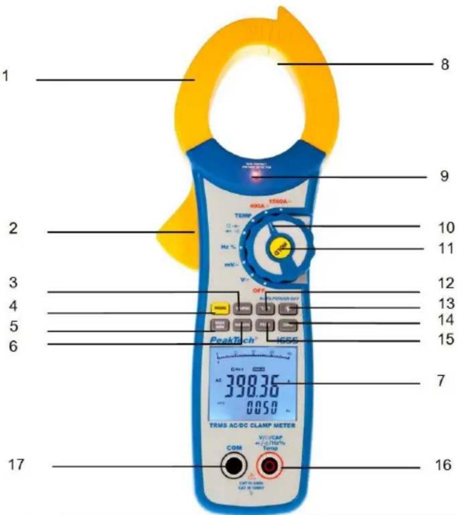
3. Instrument Layout
text_image
1 2 3 4 5 6 17 8 9 10 11 12 13 14 15 7 16 V/DCAP +/-/Hz Temp OUT V/ACM CAT IN CHIPS COM TRMS AC/DC CLAMP METER 400A 1500A TEMP OFF AIR POWER OFF V-OUT DCAM AC 390.36 0.050 mV-OUT PeakTech® 1655| 1 | Current clamp |
| 2 | Clamp opening trigger |
| 3 | RANGE button |
| 4 | MODE button |
| 5 | MAX/MIN button |
| 6 | INRUSH button |
| 7 | Backlit LCD Display |
| 8 | Non-Contact Voltage Detector |
| 9 | NCV LED Indicator |
| 10 | Function switch |
| 11 | HOLD button |
| 12 | °C/°F select button |
| 13 | Back light button |
| 14 | ZERO button |
| 15 | PEAK button |
| 16 | COM-input jack |
| 17 | V/Ω/CAP-input jacks |
| 1 | Current clampFor measuring DC/AC current |
| 2 | TriggerPress the lever to open the clamp. When the lever is released, the clamp will close again. |
| 3 | RANGE-buttonIn the Voltage, Resistance, Capacitance or Frequency the meter automatically selects the best range for the measurements being made. For measurement situations requiring that a range be manually selected, perform the following:1. Press the RANGE button. The “AUTO” display icon will turn off.2. Press the RANGE key to step through the available ranges. Observe the decimal point and units displayed until the preferred range is located.3. To exit the Manual Ranging mode and return to Autoranging, press and hold the RANGE key for 2 seconds. |
| 4 | MODE-buttonTo activate more measurement functions (Diode, Continuity, CAP) and to switch between AC and DC |
| 5 | MAX/MIN-buttonPress the MAX/MIN button to activate the MAX/MIN recording mode. The display icon "MAX" will appear. The meter will begins recording and displaying the maximum value measured.Press the MAX/MIN button and “MIN” will appear. The meter will display the minimum value measured during the recording session.Press the MAX/MIN button and “MAX MIN” will appear. The meter will display the present reading, but will continue to update and store the max and min readings.To exit MAX/MIN mode press and hold the MAX/MIN button for 2 seconds. |
| 6 | INRUSH-buttonWhen ACA is selected, press the INRUSH button to activate the inrush capture circuit.A transient condition, generally lasting 110-120 milliseconds that occurs during motor start-up. |
| 7 | LCD displayMeasurement display with automatic display of the function annunciators and backlight. |
| 8 | Non-Contact Voltage DetectorWARNING: Risk of Electrocution. Before use, always test the Voltage Detector on a known live circuit to verify proper operation.Rotate the Function switch to any measurement position.Place the detector probe tip on the conductor to be tested.If AC voltage is present, the NCV detector will turn on with a steady red light.NOTE: The conductors in electrical cord sets are often twisted. For best results, move the probe tip along a length of the cord to assure placing the tip close to the live conductor.NOTE: The detector is designed with high sensitivity. Static electricity or other sources of energy may randomly trip the sensor. This is normal operation.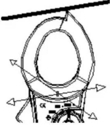 |
| 9 | LED light to indicate for the Non-Contact-Voltage Detector |
| 10 | Function switchTo select the desired measurement function. |
| 11 | HOLD buttonPress HOLD button to toggle in and out of the Data-Hold mode. In the Data-Hold mode, the “HOLD” annunciator is displayed and the last reading is frozen on the display. Press the HOLD button again to exit and resume readings. |
| 12 | °C/°F-buttonTo switch between °C and °F |
| 13 | Backlight buttonAfter turning on the backlight with "backlight" (icon) button, it turns off automatically after about 30 seconds. |
| 14 | ZERO-buttonTo activate the zero adjustment the display for the measurement functions of DC current and capacity. |
| 15 | PEAK-buttonWhen ACA or ACV is selected, pressing the PEAK button enables the peak capture circuit. The meter will now capture and display the maximum and minimum peaks of the waveform. |
| 16 and 17 | Input sockets Input jacks for using with the supplied test leads and thermocouple for all measurement functions except DC - and AC currents |
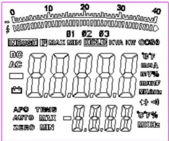
3.1. Display icons Description
text_image
0 10 20 30 40 INRUSH F MAX MIN HOLD KVA KW COSO DC AC 0F mNA mV% munF WKHE 计-0 APO TRMS AUTO MAX ZERO MIN -0.0.0.0 CF% MKHEHOLD Data Hold
APO Auto Power Off
AUTO Autoranging
P Peak Hold
DC Direct Current
AC Alternating Current
MAX Max reading
MIN Min reading
Low battery
ZERO DCA or CAP zero
mV or V Milli-volts or Volts (Voltage)
Ω Ohms (Resistance)
A Amperes (Current)
F Farad (Capacitance)
Hz Hertz (Frequency)
% Duty Ratio
°F and °C Fahrenheit and Celsius units (Temperature)
n, m, μ, M, k Unit of measure prefixes: nano, milli, micro, mega, and kilo
•))) Continuity test

Diode test
4. Technical data
| Display | 40x45mm Multifunction-LCD-display with max. reading of 40000; function annunciators and bargraph |
| Jaw opening | 52 mm max. |
| Polarity | automatic: switchover in case of negative readings prior to the measurement display. |
| Over-Range indication | „OL“ is displayed |
| Low battery indication | Battery symbol is displayed |
| Measurement rate | 2x per second |
| PEAK detector | >1ms |
| Input resistance | 10MΩ (V DC/AC) |
| AC-bandwidth | 50 to 400Hz (A AC; V AC) True RMS |
| Crest factor | 3.0: 40/400A ranges1.4: 1000A range (at 50/60Hz and 5% to 100% of range) |
| Auto power off | 30 minutes |
| Operating temperature | 5°C – 40°C / <80% RH |
| Operation Altitude | 2000m (7000ft.) |
| Storage temperature | -20°C - +60°C / <80% RH |
| Battery | 9V-battery (NEDA 2604) |
| Dimensions (WxHxD) | 105x293x45mm |
| Weight | 536g |
5. Specifications
| Function | Range | Accuracy (% of reading) |
| DC Current | 400.00 A DC | ± (2.5% +30digits) |
| 1500.0 A DC | ± (2.8% +50digits) | |
| AC Current True RMS (50Hz to 60 Hz) | 400.00 A AC | ± (3.5% +50digits) |
| 1500.0 A AC | ± (3.5% +50digits) | |
| All AC voltage ranges are specified from 5% of range to 100% of range | ||
| DC Voltage | 400.00 mV DC | ± (0.2% + 5 digits) |
| 4.0000 V DC | ± (0.2% + 4 digits) | |
| 40.000 V DC | ||
| 400.00 V DC | ||
| 1000.0 V DC | ± (0.5% + 4 digits) | |
| AC Voltage True RMS (50 Hz to 1000 Hz) | 400.00 mV AC | ± (1.0% + 40 digits)(50/60Hz) |
| 4.0000 V AC | ± (1.5% + 30 digits) | |
| 40.000 V AC | ||
| 400.00 V AC | ||
| 750.0 V AC | ± (2.0% + 40 digits) | |
| All AC voltage ranges are specified from 5% of range to 100% of range | ||
| Resistance | 400.00 Ω | ± (0.5% + 30 digits) |
| 4.0000 kΩ | ± (1.0% + 4 digits) | |
| 40.000 kΩ | ||
| 400.00 kΩ | ||
| 4.0000 MΩ | ± (2.0% + 10digits) | |
| 40.000 MΩ | ± (3.0% + 10 digits) | |
| Capacitance | 400.00 nF | ±(3.5% reading + 40digits) |
| 4000.0 nF | ±(3.5% reading + 10digits) | |
| 40.00 μF | ||
| 400.0 μF | ||
| 4.000 mF | ±(5% reading + 10 digits) | |
| 20.00 mF | ±(15% reading + 50 digits) | |
| 40.00 mF | Not specified | |
| Frequency | 40.000 Hz | ±(0.3% reading + 2 digits) |
| 400.00 Hz | ||
| 4.0000 kHz | ||
| 40.000 kHz | ||
| 400.00 kHz | ||
| 4.0000 MHz | ||
| 40.000 MHz | ||
| Sensitivity: 0.8V rms min. @ 20% to 80% duty cycle and <100kHz; 5Vrms min @ 20% to 80% duty cycle and >100kHz. | ||
| Duty Cycle | 10.0 to 95.0% | ± (1.0% reading + 2 digits) |
| Pulse width: 100μs - 100ms, Frequency: 10Hz to 100kHz | ||
| Temp(type-K) | -100.0 to1000.0°C | ±(1.0% reading + 3°C) |
| -148.0 to 1832.0°F | ±(1.0% reading + 4.5°F) | |
| (probe accuracy not included) | ||
Diode and audible Continuity Test
| Range | Description | Test conditions |
| Display read approx. forward voltage of diode | Forward DC current approx. 0,3 mA. Reversed DC voltage approx 2,8 V | |
| .))) | Built-in buzzer sounds if conductance is less than approx 50 Ω | Open circuit voltage approx 2,8 V. Forward DC current approx. < 0,5 mA. |
6. How to make measurements
Before making any measurements read safety precautions. Always examine the instrument and accessories used with the instrument for damage, contamination (excessive dirt, grease, etc) and defects. Examine the test leads for cracked or frayed insulation and make sure the lead plugs fit snugly into the instrument terminals. If any abnormal conditions exist, do not attempt to make any measurements.
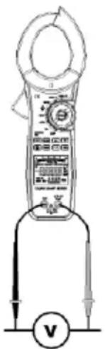
6.1. Voltage measurements
- Turn off power to the device under test and discharge all capacitors.
- Select mV or V-function with the rotary function-switch.
-
Select the desired AC voltage range or DC voltage range, by pressing MODE-button.
-
Plug the black test lead into the COM input jack on the meter and connect the test lead tip to a grounded point (the reference point for measurement of voltage).
WARNING! To avoid possible electric shock, instrument damage and/or equipment damage, do not attempt to take any voltage measurements if the voltage is above 1000 V AC/DC are the maximum voltages that this instrument is designed to measure. The “COM” terminal potential should not exceed 1000 V measured to ground.
-
Plug the red test lead into the V/Ω/CAP/ /Hz - input jack on the meter and connect the circuit where a voltage measurement is required. Voltage is always measured in parallel across a test point. Turn on power the circuit/device to be measured and make the voltage measurement reduce the range setting if set too high until a satisfactory reading is obtained.
-
After completing the measurement, turn off power to the circuit/device under test, discharge all capacitors and disconnect the meter test leads.
text_image
Diagram of a digital multimeter with labeled components and a voltmeter connected to its side.6.2. Current Measurements
WARNING! This clamp is designed to take current measurements on circuits with a maximum voltage difference of 1000 V AC/DC between any conductor and ground potential. Using the clamp for current measurements on circuits above this voltage may cause electric shock, instrument damage and/or damage to the equipment under test. Before measuring current make certain that the test leads are removed from the instrument.
The clamp is overload protected up to 1000 V AC/DC for up to 1 Min. Do not take current readings on circuits where the maximum current potential is not known. Do not exceed the maximum current that this instrument is designed to measure.
- Set Function Switch to 400 A / 1500 A.
- Press the trigger to open the transformer jaws and clamp them around a conductor. Jaws should be completely closed before taking a reading.
- Select the desired AC or DC range by pressing MODE-button.
- DCA Zero: The zero feature removes offset values and improves the accuracy for DC current measurements.
- Perform a zero adjustment by selecting 400A/1500A DC with the function selector switch and without a conductor in the clamp, press the ZERO button.
- The display shows zero. The offset value is now stored and removed from all measurements
- Now perform your current measurement, as described in points 1 – 6.
Note:
Frequency: If the measurement function 400A/1500A AC is selected, you can read in the secondary display, the frequency of the measured current value.
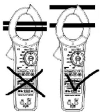
- The most accurate reading will be obtained by keeping the conductor across centre of the transformer jaws. The reading will be indicated on the display.
text_image
Diagram showing two identical circuit clamp devices with control knobs and a crossed-out X marks indicating no protection or disapproval.6.3. Resistance measurements
WARNING! Attempting resistance or continuity measurements on live circuits can cause electric shock, damage to the instrument and damage to the equipment under test.
Resistance measurements must be made on de-energized (DEAD) circuits only for maximum personal safety. The electronic overload protection installed in this instrument will reduce the possibility of damage to the instrument bus not necessarily avoid all damage or shock hazard.
- Turn off any power to the resistor to be measured. Discharge capacitors. Any voltage present during a resistance measurement will cause inaccurate readings and could damage the meter if exceeding the overload protection of 1000 V DC or AC.
- Insert the black test leads into the COM and the red test lead into the V/Ω/CAP/→/Hz - input terminals respectively.
- Select the desired ohm ( ) range.
- Connect the black and red test probe tips to the circuit or device under test, making sure it is de-energized first.
- Open circuits will be displayed as an overload OL condition.
- Test lead resistance can interfere when measuring low resistance readings and should be subtracted from resistance measurements for accuracy. Select lowest resistance range and make the test leads short together.
The display value is the test lead resistance to be subtracted.
- After completing measurement, disconnect the test leads.
6.4. Continuity testing
- Set the rotary switch to the position
- Select the ·))) function by pressing the MODE-button.
- Follow step 2 and 4; as for resistance measurements.
- An audible tone will sound for resistance less than approx. 50 Ω. After all measurements are completed, disconnect the test leads from the circuit and from the input terminals.
6.5. Diode testing
CAUTION! Measurements must only be made with the circuit power OFF.
- Set the rotary switch to the position.
- Select the function by pressing MODE-button.
-
Follow steps 2 and 4 as for resistance measurements.
-
The red test lead should be connected to the anode and the lack lead to the cathode. For a silicon diode, the typical forward voltage should be about 0.7 V or 0.4 V for a germanium diode.
- If the diode is reverse biased or there is an open circuit the display shows "OL".
6.6. Capacitance measurement
- Turn off power to the device under test and discharge all capacitors.
- Discharge all voltage from the capacitor before measuring is capacitance value.
Note: A safe way to discharge a capacitor is to connect a 100 kΩ resistor across the two capacitor leads.
- Set the rotary switch to the V/Ω/CAP/ /Hz range.
- Select the CAP-function by pressing MODE-button.
- Plug the black and red test leads into the COM and V/Ω/CAP/→/Hz input terminals respectively. Touch the probes to the capacitor. Always observe polarity makings when measuring capacitors.
- For best accurate results press the ZERO-button before measurement.
- Read capacitance value directly from the display.
- After completing the measurement, disconnect the test leads.
6.7. Frequency measurements
- Set the rotary switch to the Hz/% position
- Plug the black and red test leads into the COM and V/Ω/CAP/ ^+ /Hz input terminals respectively.
- Attach the probe tips to the points across which the frequency is to be measured, and read the result directly from the display.
- Read the Duty Ratio on the cover small display.
- Disconnect the test leads.
6.8. Temperature measurements
Warning!
To avoid electric shock, disconnect both test probes from any source of voltage before making a temperature measurement.
- Set the rotary switch to TEMP position.
- Insert the temperature-adaptor in the V/Ω-input jacks (+) and the COM-socket (-) respective to the polarity-markings on the temperature-adaptor.
- Select the desired measuring unit °C or °F by pressing MODE-button.
- Insert the K-type thermocouple into the temperature socket, making sure to observe the correct polarity.
- Touch the temperature probe head to the part whose temperature you wish to measure. Read the temperature in the display.
7. Replacing the battery
WARNING! To avoid electrical shock, disconnect the test leads and any input signals before replacing the battery. Replace only with same type of battery.
This meter is powered by a NEDA type 1604 or equivalent 9 V-battery. When the meter displays the battery symbol the battery must be replaced to maintain proper operation. Use the following procedure to replacing the battery.
- Disconnect test leads from any live source, turn the rotary switch to OFF and remove the test leads from the input terminals.
- The battery cover is secured to the bottom case by a screw. Using a screwdriver, remove the screw from the battery cover and remove the battery cover.
- Remove the battery and replace with a new equivalent 9 V-battery.
- Replace the battery cover and reinstall the screw.
Note:
Batteries which are used up, dispose duly. Used up batteries are hazardous and must be given in the for this being supposed collective container.
7.1. Statutory Notification about the Battery Regulations
The delivery of many devices includes batteries, which for example serve to operate the remote control. There also could be batteries or accumulators built into the device itself. In connection with the sale of these batteries or accumulators, we are obliged under the Battery Regulations to notify our customers of the following:
Please dispose of old batteries at a council collection point or return them to a local shop at no cost. The disposal in domestic refuse is strictly forbidden according to the Battery Regulations. You can return used batteries obtained from us at no charge at the address on the last side in this manual or by posting with sufficient stamps.

natural_image
Simple line drawing of a trash bin with no text or symbolsBatteries, which contain harmful substances, are marked with the symbol of a crossed-out waste bin, similar to the illustration shown left. Under the waste bin symbol is the chemical symbol for the harmful substance, e.g. „Cd“ for cadmium, „Pb“ stands for lead and „Hg“ for mercury.
You can obtain further information about the Battery Regulations from the Bundesministerium für Umwelt, Naturschutz und Reaktorsicherheit (Federal Ministry of Environment, Nature Conservation and Reactor Safety).
8. Maintenance
Maintenance consists of periodic cleaning and battery replacement. The exterior of the instrument can be cleaned with a dry clean cloth to remove any oil, grease or grime. Never use liquid solvents or detergents.
Repairs or servicing not covered in this manual should only be performed by qualified service personnel.
All rights, also for translation, reprinting and copy of this manual or parts are reserved.
Reproduction of all kinds (photocopy, microfilm or other) only by written permission of the publisher.
This manual considers the latest technical knowing. Technical changings which are in the interest of progress reserved.
We herewith confirm, that the units are calibrated by the factory according to the specifications as per the technical specifications.
We recommend to calibrate the unit again, after 1 year.