WET10A33A - Air Conditioning Friedrich - Free user manual and instructions
Find the device manual for free WET10A33A Friedrich in PDF.

User questions about WET10A33A Friedrich
0 question about this device. Answer the ones you know or ask your own.
Ask a new question about this device
Download the instructions for your Air Conditioning in PDF format for free! Find your manual WET10A33A - Friedrich and take your electronic device back in hand. On this page are published all the documents necessary for the use of your device. WET10A33A by Friedrich.
USER MANUAL WET10A33A Friedrich
natural_image
Line drawing of a white air conditioner unit with control panel and ventilation grille (no text or symbols)Air Conditioners and Heat Pumps
WallMaster®
115-Volt: WCT08, WCT10, WCT12
230-Volt: WCT10, WCT12, WCT16, WET10, WET12, WET16, WHT12
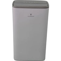
Thank you for your decision to purchase the Friedrich High Efficiency Air Conditioner. Your new Friedrich has been carefully engineered and manufactured to give you many years of dependable, efficient operation, maintaining a comfortable temperature and humidity level. Many extra features have been built into your unit to assure quiet operation, the greatest circulation of cool, dry air, and the most economic operation.
THANK YOU, on behalf of our entire company, for making such a wise purchase.
Register your air conditioner
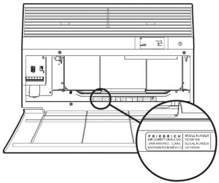
Model information can be found on the name plate behind the front cover.
Please complete and mail the owner registration card furnished with this product, or register online at www.friedrich.com.
For your future convenience, record the model information here.
MODEL NUMBER
SERIAL NUMBER
PURCHASE DATE
Table of Contents
Safety Precautions 4
WARNING: Before Operating Your Unit 5
Standard Filter Cleaning / Installation Instructions 6
Control Panel Operation 7
New WallMaster Control Options 20
Wi-Fi Set-Up Instructions 21
Control Panel Operation Instructions 22
Remote Control Operation 23
Remote Effectiveness 23
Airflow Selection and Adjustment 23
Installation Instructions 24
Installation Instructions for WSE Sleeve 25
WallMaster Chassis Installation Instructions 27
Troubleshooting Tips 29
Warranty 31
Safety Precautions
Your safety and the safety of others is very important.

We have provided many important safety messages in this manual and on your appliance. Always read and obey all safety messages.
This is a safety Alert symbol.
This symbol alerts you to potential hazards that can kill or hurt you and others.

WARNING
All safety messages will follow the safety alert symbol with the word "WARNING" or "CAUTION". These words mean:

CAUTION
Indicates a hazard which, if not avoided, can result in severe personal injury or death and damage to product or other property.
Indicates a hazard which, if not avoided, can result in personal injury and damage to product or other property.
NOTICE
All safety messages will tell you what the potential hazard is, tell you how to reduce the chance of injury, and tell you what will happen if the instructions are not followed.
Indicates property damage can occur if instructions are not followed.

WARNING

Refrigeration system under high pressure
Do not puncture, heat, expose to flame or incinerate.
Only certified refrigeration technicians should service this equipment.
R410A systems operate at higher pressures than R22 equipment. Appropriate safe service and handling practices must be used.
Only use gauge sets designed for use with R410A.
Do not use standard R22 gauge sets.
THINK
SAFETY FIRST

WARNING AVETISSEMENT ADVERTENCIA
Do not remove, disable or bypass this unit's safety devices. Doing so may cause fire, Doing so may cause fire, injuries, or death.

ISSEMENT ADVERTEMIA
WARNING: Before Operating Your Unit

WARNING

Electrical Shock Hazard
Make sure your electrical receptacle has the same configuration as your air conditioner's plug. If different, consult a Licensed Electrician.
Do not use plug adapters.
Do not use an extension cord.
Do not remove ground prong.
Always plug into a grounded 3 prong outlet.
Failure to follow these instructions can result in death, fire, or electrical shock.
Make sure the wiring is adequate for your unit.
If you have fuses, they should be of the time delay type. Before you install or relocate this unit, be sure that the amperage rating of the circuit breaker or time delay fuse does not exceed the amp rating listed in Table 1.
DO NOT use an extension cord.
The cord provided will carry the proper amount of electrical power to the unit; an extension cord may not.
Make sure that the receptacle is compatible with the air conditioner cord plug provided.
Proper grounding must be maintained at all times. Two prong receptacles must be replaced with a grounded receptacle by a certified electrician.
The grounded receptacle should meet all national and local codes and ordinances. You must use the three prong plug furnished with the air conditioner. Under no circumstances should you remove the ground prong from the plug.
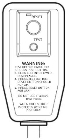
Test the power cord.
All Friedrich room air conditioners are shipped from the factory with a Leakage Current Detection Interrupter (LCDI) equipped power cord. The LCDI device on the end of the cord meets the UL and NEC requirements for cord connected air conditioners.
To test your power supply cord:
- Plug power supply cord into a grounded 3 prong outlet.
- Press RESET (see Figure 1).
- Press TEST, listen for click; the RESET button trips and pops out.
- Press and release RESET (Listen for click; RESET button latches and remains in). The power cord is ready for use.
NOTICE
Do not use the LCDI device as an ON/OFF switch.
Failure to adhere to this precaution may cause premature equipment malfunction.
Once plugged in, the unit will operate normally without the need to reset the LCDI device. If the LCDI device fails to trip when tested or if the power supply cord is damaged, it must be replaced with a new power supply cord from the manufacturer. Contact our Technical Assistance Line at (800) 541-6645. To expedite service, please have your model number available.
| Table 1 | ||||
| MODEL | CIRCUIT RATING OR TIME DELAY FUSE | REQUIRED WALL RECEPTACLE | ||
| AMP VOLT | NEMA NO. | |||
| WCT08, WCT10, WCT12 15 125 5-15P |  | |||
| WCT10, WCT12, WCT16 15 250 6-15P |  | |||
| WET10, WET12, WET16, WHT12 20 | 250 6-20P |  | ||
Figure 1
FRR072
Standard Filter Cleaning / Installation Instructions
HOW TO CLEAN YOUR AIR FILTER
Your Friedrich room air conditioner is equipped with a permanent/washable mesh air filter. The filter serves to remove dust, pollen, and other impurities from the air.
CHECK FILTER LIGHT
Your Friedrich room air conditioner is equipped with a check filter light that will illuminate after *45–60 days of fan operation.
To reset the CHECK FILTER reminder press the CHECK FILTER button. (While the reminder is set for 45–60 days of operation, we recommend checking the filter every 30 days for optimal performance.)
*Actual timer is set for 1000 hours of fan cycle operation.
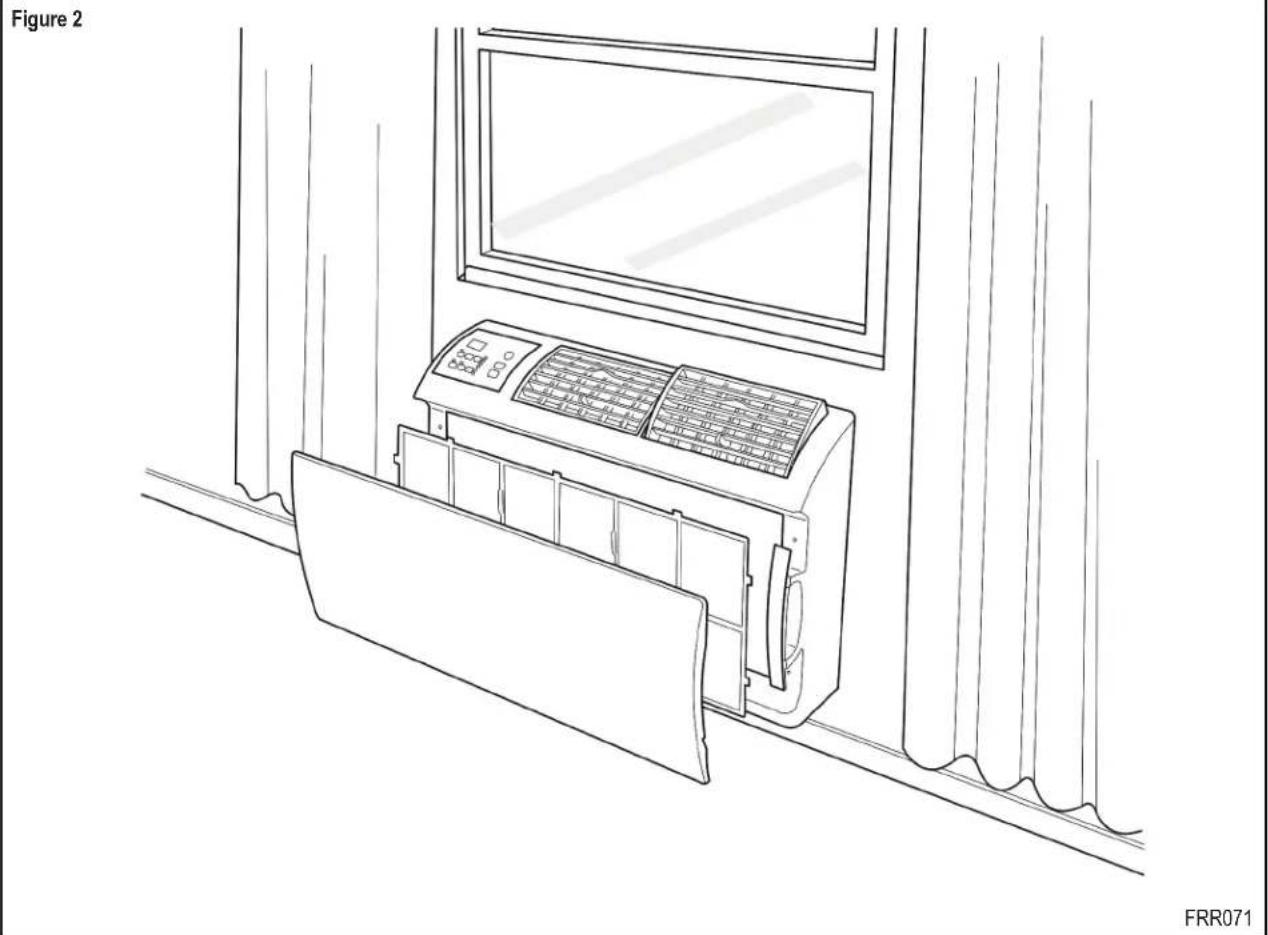
FILTER ACCESS
Remove the FRONT PANEL. Using the handles, pull panel out until it is released from the two retaining snaps. Place the cover aside carefully. Remove the filter by pulling it from the handles releasing it from the slots on the frame. Wash the filter with water to remove all dust and then rinse, remove water excess and let it dry – do not twist – then replace the filter by inserting each tab in their respective slot.
Replace the FRONT PANEL by positioning one of the sides in the snaps of the handle first and then the other side, make sure that both snaps are correctly aligned and the logo is in the right position.
natural_image
Line drawing of an air conditioner unit mounted on a wall, with a window and curtain in the background (no text or symbols)Control Panel Operation
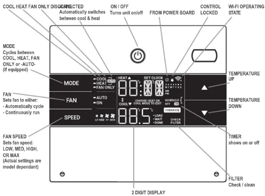
All of the control panel function buttons and mode icons can be viewed in Figure 3.
Power On – Press the button to turn on the air conditioner. The power button illuminates to indicate that the power is on. The backlight on the power switch will automatically turn off after 20 seconds of inactivity. The remote control can also be used to turn power ON / OFF (See Remote Control).
Display - The display is a high efficiency LCD with a built-in backlight. After 20 seconds of inactivity, the display switches off. Touching any button automatically changes the display to full brightness.
There are three control push buttons on each side of the display.
Figure 3
| SYSTEM | FAN MODE | FAN SPEED | TEMPERATURE | TIMER | IR WINDOW | ON / OFF |
| Cycles between AUTO,HEAT, COOL, or FAN ONLY (if equipped) | Sets fan to either: - Cycle automatically - Run continuously | Sets fan speed: LOW, MED, HIGH or AUTO (if equipped) | Increment UP | Turns ON or OFF | Do not block | Turns unit on/off |
| TEMPERATURE | ||||||
| Increment DOWN |
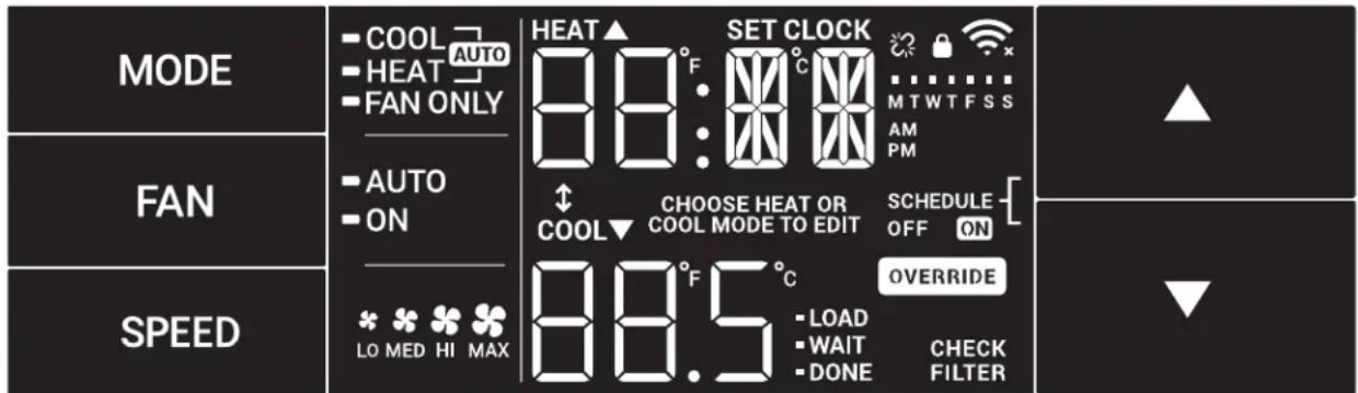
Figure 4
Control Panel Operation
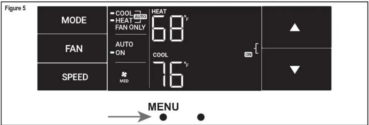
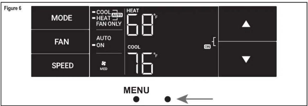
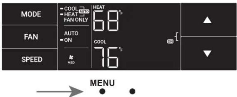
Accessing Sub-Menus
The leftmost MENU button accesses the sub-menu. See Figure 5.
The arrow buttons navigate the 6 menu options (See Figure 6):
-LIM-LOCK
-TM-CnCT
-F-C -diAG
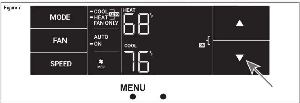
The rightmost button exits the menu. See Figure 7.
Control Panel Operation
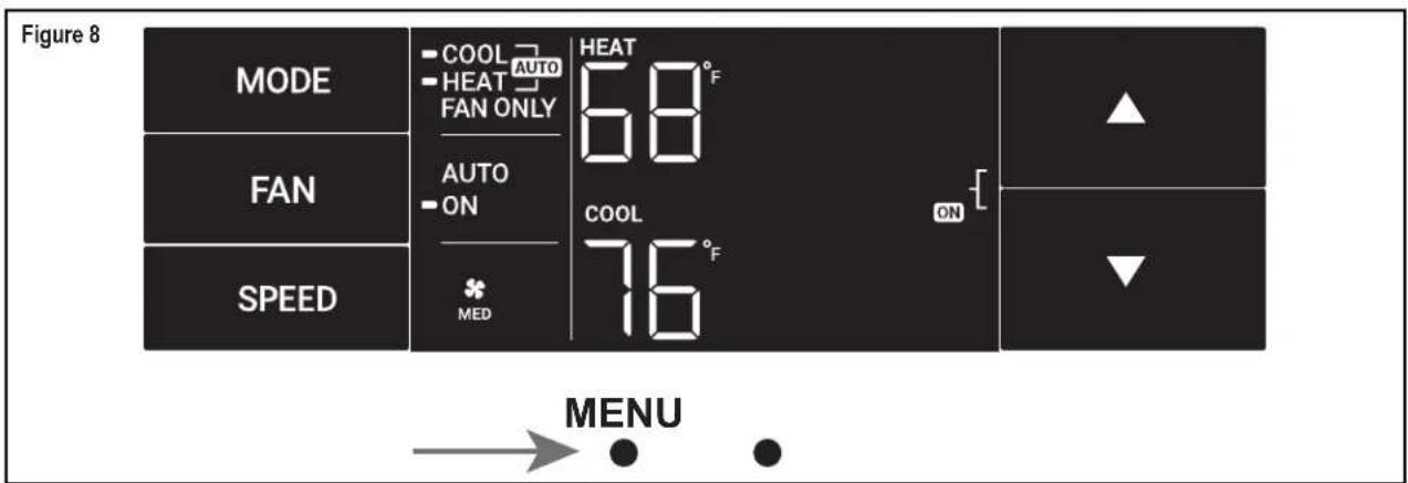
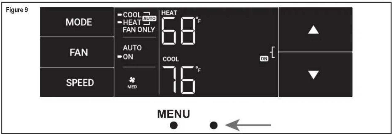
Navigating Inside the Sub-Menus
The leftmost MENU button moves you forward through the sub-menu. See Figure 8.
The rightmost button moves you backward once inside the LIM and TM menus. See Figure 9.
Control Panel Operation
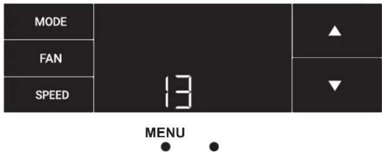
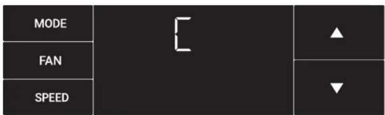
The LIM Menu
This is the limit menu. See Figure 10.
Upon entering the menu, the first option will be to set the lower setpoint limit using the arrow buttons. See Figure 11.
Then you can set the higher setpoint limit using the arrow buttons. See Figure 12.
Pressing the leftmost button completes the limit setting. See Figure 13.
Figure 10
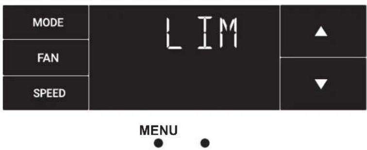
Figure 11
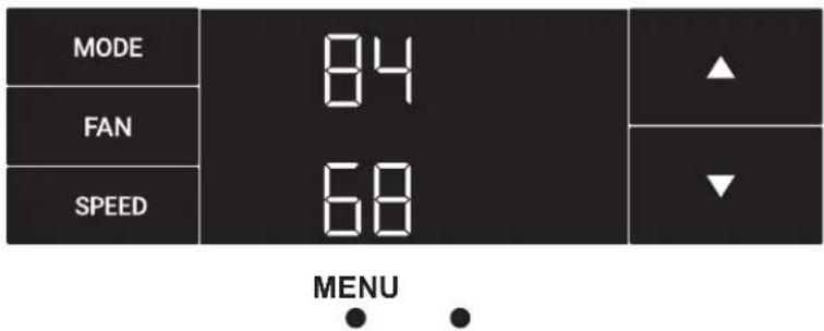
Figure 12
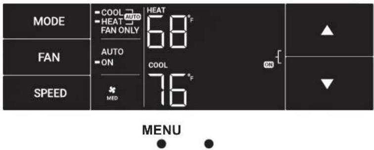
Figure 13
Control Panel Operation
The TM Menu
This is the TM menu used to set a timer. See Figure 14.
In the menu, you set the current time using the arrow buttons. See Figure 15. (Note: These two "set clock" steps will be skipped if the unit is already connected to Wi-Fi.)
First, set the hour.
Using the leftmost button, you switch to the minutes and complete setting the time. See Figure 16.
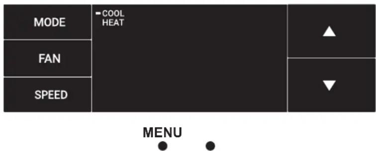
You select your mode. Either cool, heat, or auto. Toggle these using the arrow buttons. See Figure 17. (Note: cooling-only models skip this step.)
The process is the same for all three modes. Auto mode will be shown as the example.
Figure 14
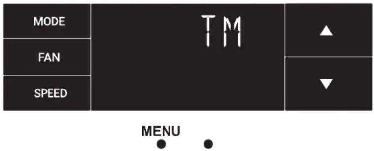
Figure 15
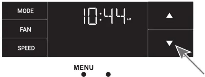
Figure 16
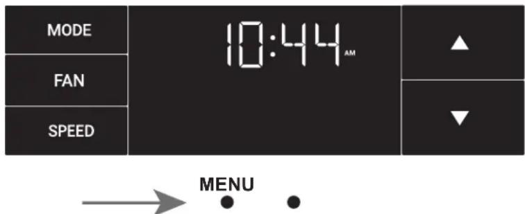
Figure 17
Control Panel Operation
The TM Menu continued
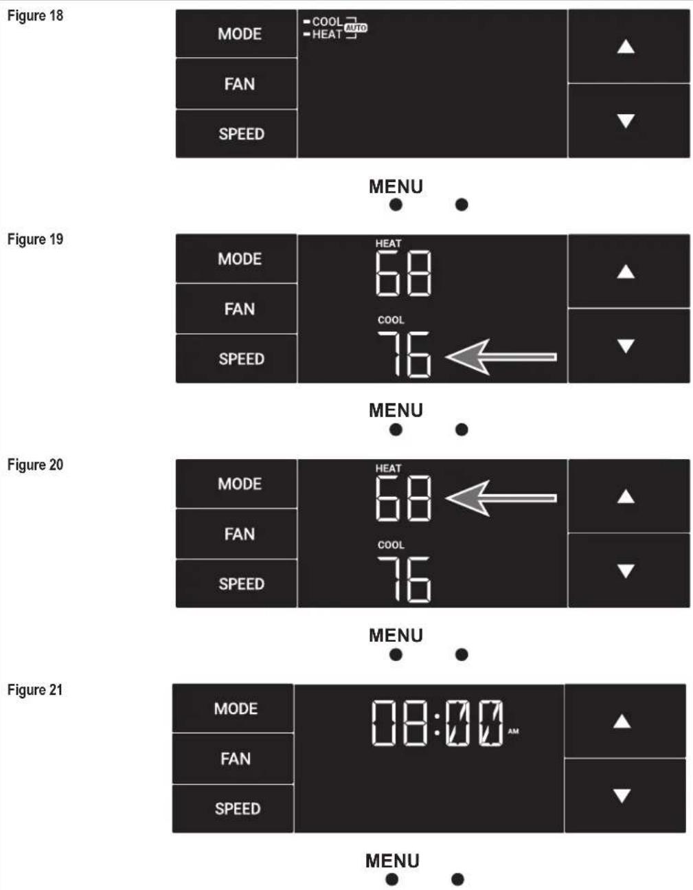
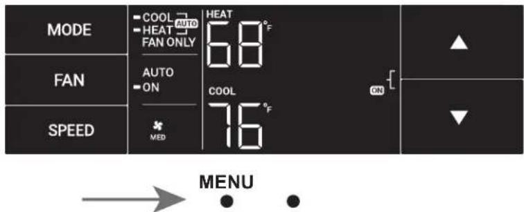
Auto mode selected. See Figure 18.
Set the cool setpoint for your first timer period using the arrow buttons. The cooling mode timer only sets the cool setpoint. See Figure 19.
Next, set the heat setpoint for your first timer period. The heating mode timer only sets the heat setpoint. See Figure 20.
Note: The auto mode timer sets both the cool and heat setpoint.
Set the time to start the first timer period. See Figure 21.
Control Panel Operation
The TM Menu continued
Set the cool setpoint for the second scheduled timer. See Figure 22.
Set the heat setpoint for the second timer.
Set the time to start the second timer period. See Figure 23.
Press the leftmost button to complete the time timer setup. See Figure 24.
Figure 22
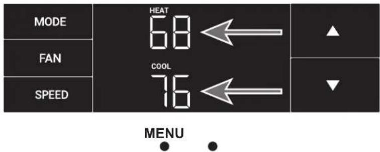
Figure 23
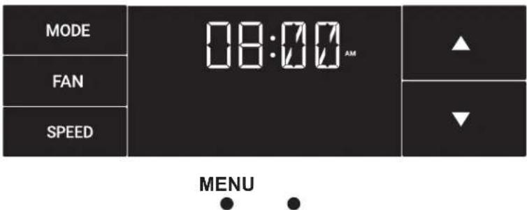
Figure 24
Control Panel Operation
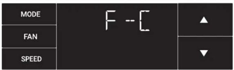
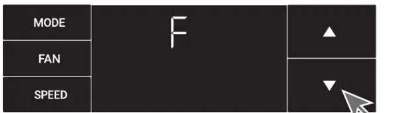
The F-C Menu
This menu is used to toggle between Fahrenheit and Celsius.
This is the Fahrenheit/ Celsius Menu. See Figure 25.
Using the arrow buttons on the right side switches it from Fahrenheit to Celsius. See Figures 26 and 27.
Figure 25
MENU
Figure 26
MENU
Figure 27

MENU
Control Panel Operation
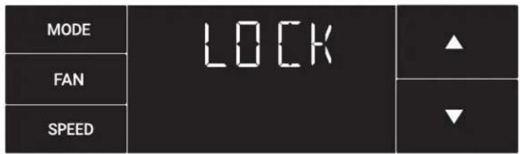
The Lock Menu
This menu is used to lock the changing setting with a password.
This is the Lock Menu. See Figure 28.
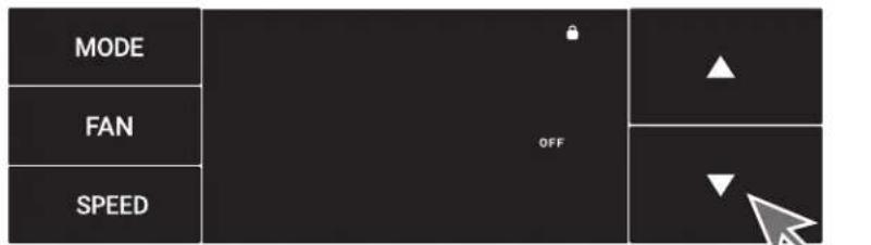
The default is the off setting. Use the arrows to toggle between off and on. See Figure 29.
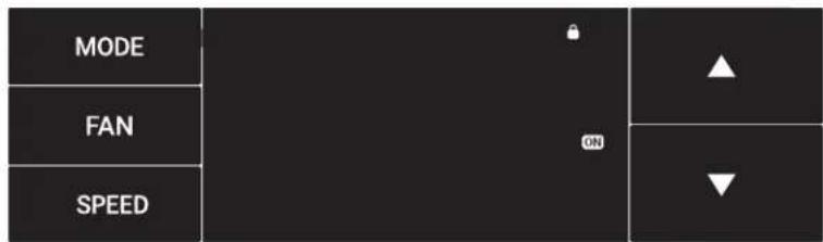
This is LOCK on. See Figure 30.
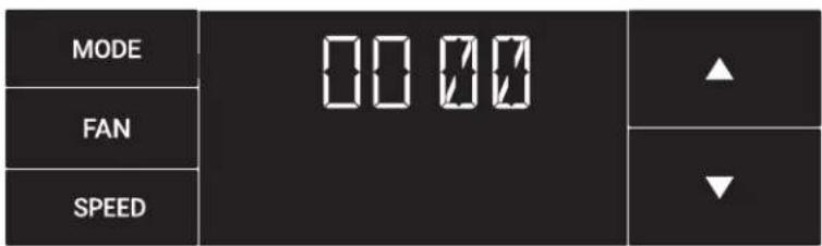
Set the first digit of the password using the arrow buttons. Use the leftmost button to proceed to the next digit. See Figure 31.
Figure 28
MENU
Figure 29
MENU
Figure 30
MENU
Figure 31

Control Panel Operation
The Lock Menu continued
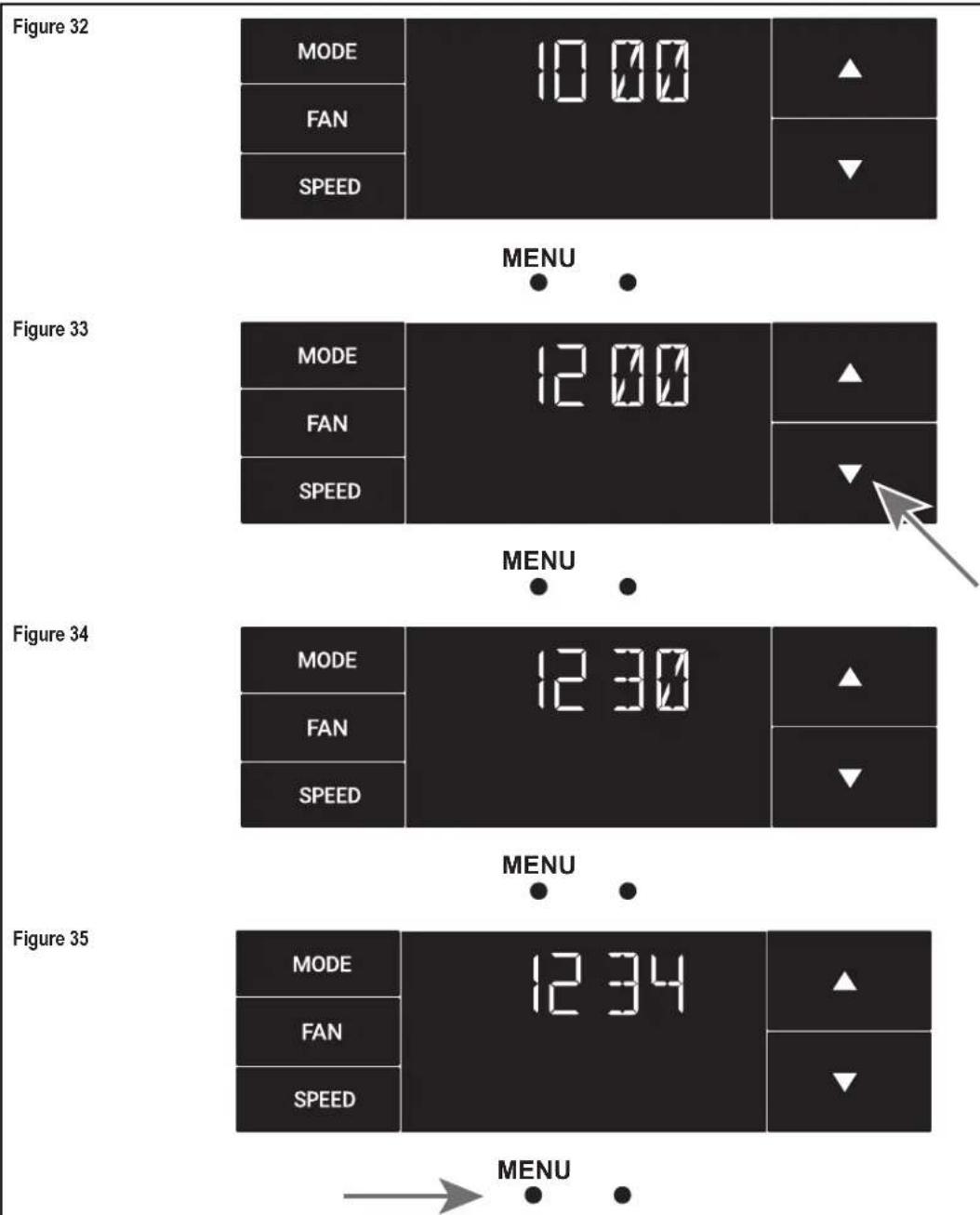
Set the second digit of the password using the same method. See Figure 32.
Set the third digit of the password using the same method. See Figure 33.
Set the fourth digit of the password using the same method. See Figures 34.
Press the leftmost button to complete the password process. See Figure 35.
other
| Panel | Metric | Value | |---|---|---| | Figure 32 | MODE | 10.00 | | Figure 32 | FAN | ▲ | | Figure 32 | SPEED | ▼ | | Figure 33 | MODE | 12.00 | | Figure 33 | FAN | ▲ | | Figure 33 | SPEED | ▼ | | Figure 34 | MODE | 12.30 | | Figure 34 | FAN | ▲ | | Figure 34 | SPEED | ▼ | | Figure 35 | MODE | 12.34 | | Figure 35 | FAN | ▲ | | Figure 35 | SPEED | ▼ | MENU MENU MENUControl Panel Operation
The Lock Menu continued
The ON on the right side of the display shows the lock function is active. To go back into the menu, select the leftmost button again. See Figure 36.
Enter the password in the same manner it was created. See Figure 37.
Entering the correct password will give the user access to all of the submenus. See Figure 38.
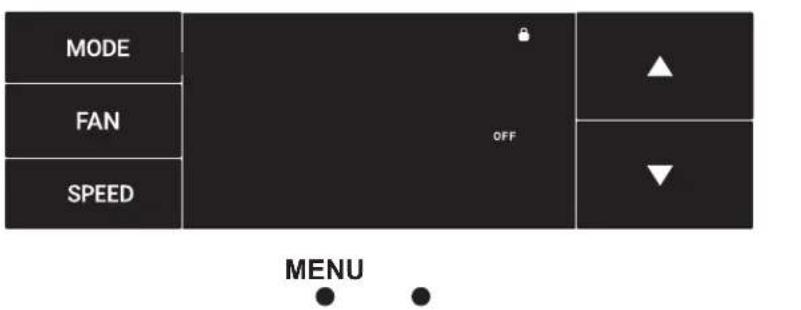
Accessing the lock menu will allow you to toggle lock OFF if needed. See Figure 39.
Figure 36
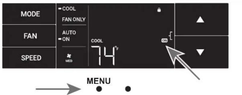
Figure 37
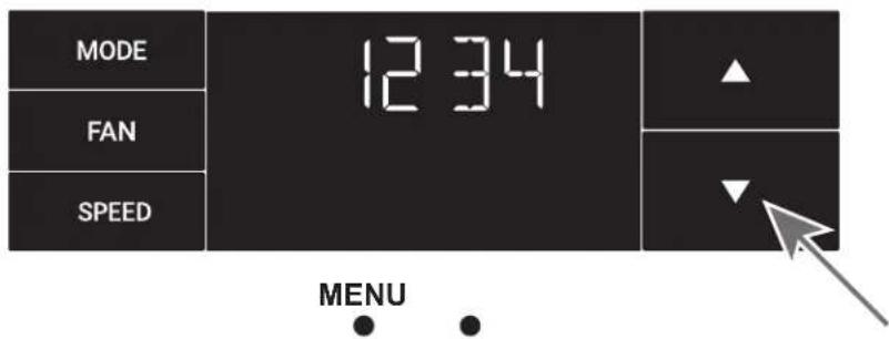
Figure 38
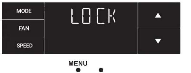
Figure 39
Control Panel Operation
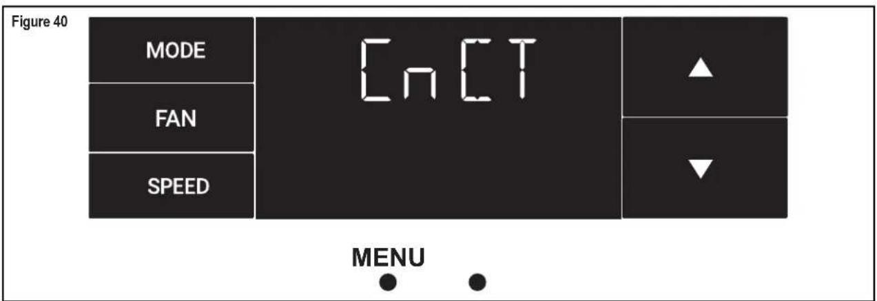
The CnCT Menu
This menu is used to turn on Wi-Fi connection.
This is the CnCT menu. Pressing the leftmost button will activate Wi-Fi. See Figure 40.
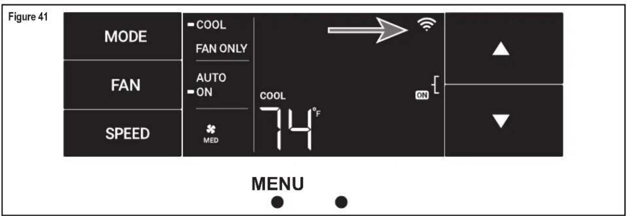
The Wi-Fi symbol in the top right corner of the display shows Wi-Fi connection is on. See Figure 41.
Control Panel Operation
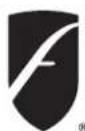
The diAG Menu
This menu is used to access the diagnostic codes. See Figure 42.
Selecting this sub-menu shows the E that represents "Error."
See Figure 43.
Toggle through the error codes using the arrow keys. See Figure 44.
Figure 42
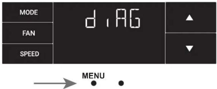
Figure 43
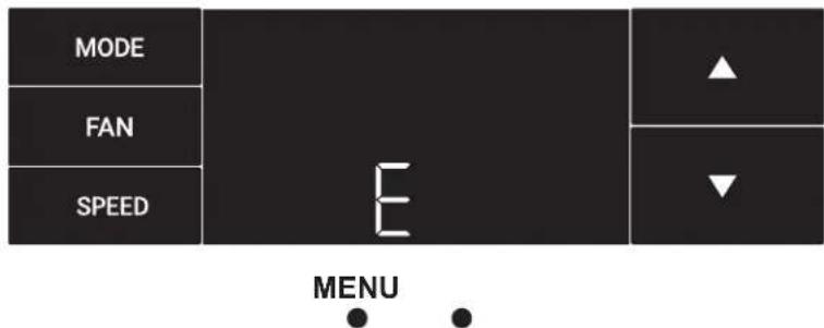
Figure 44
New WallMaster® Control Options
The new WallMaster gives you a variety of options for control, programming, and scheduling including wireless capabilities.
Wireless Programming and Control:
Friedrich Connect allows you to conveniently control, program, and monitor your air conditioning unit remotely from a smartphone or computer.
Pre-Programmed Scheduling Options:
Your unit's digital control comes equipped with a 24-hour timer.
24-Hour Timer
The 24-hour timer allows you to set 2 temperature changes at pre-set times or a unit control panel.
Customizable Programming Options:
Customizable timers, with up to four temperature adjustments per day, can be set using Friedrich Connect for one or multiple units.
See www.friedrich.com for complete details on Friedrich Connect.
natural_image
Line drawing of a white air conditioner unit with control panel and ventilation grille (no text or symbols)Wi-Fi Set-Up Instructions
Below are the set-up instructions for Wi-Fi to use your unit wirelessly.
Follow the instructions below:
STEP 1. Using a mobile device such as a smartphone or laptop, navigate to www.FriedrichConnect.com.
STEP 2. Sign-in using your username and password.
STEP 3. Click the "Add Device" button.
STEP 4. Select the time zone the device is located in and click the "Next" button.
STEP 5. To start the setup process click the menu button on the home screen of your WallMaster model.
STEP 6. Using the up and down arrows, navigate to the CnCT screen (Figure 45).
STEP 7. Click the menu button, this will begin the setup process for your Friedrich Connect enabled device.
STEP 8. Click the "Next" button on your mobile device.
STEP 9. Follow the on-screen steps to finish adding the device to your account.
Figure 45
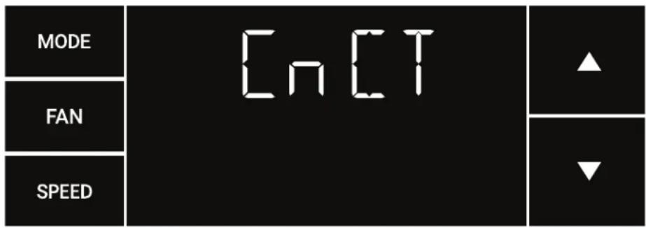
Figure 46
| MODE | COOL HEAT FAN ONLY | COOL▼ 72 | ▲ |
| FAN | AUTO ON | ||
| SPEED | HI | ▼ |
Control Panel Operation Instructions
SYSTEM - The MODE button allows you to sequentially select up to four modes of operation:
AUTO Available on select models
COOL
HEAT Available on select models
FAN ONLY
AUTO FAN (No Cooling Demand)
When in AUTO mode, the fan only operates when the system has a demand to cool or heat the room.
In the ON fan mode, the fan operates all the time. The system periodically cools or heats the fan's airflow but the flow of air does not stop.
UP and DOWN Arrows - Pressing either an UP or DOWN button changes the system's setpoint (desired room temperature). These buttons are also used to make system parameter changes later in this manual.
One press equals 1 degree of change in Fahrenheit mode. One press equals 0.5 degree change in Celsius mode.
TIMER
The timer can be engaged or disengaged from the control panel. This is done by pressing or holding the UP and DOWN arrows simultaneously for three seconds.
OTHER FUNCTIONS
°F-°C Select
To switch from degrees Fahrenheit (F) to Celsius (C), press the MENU button and enter the F-C sub-menu.
FAN SPEED - Depending on your model, the FAN SPEED button allows you to toggle between three or four modes of operation: LOW, MEDIUM, HIGH and MAX.
Alerts
When the filter needs to be cleaned or replaced, the CHECK FILTER icon displays.
The alert can be dismissed by pressing the FAN MODE and TIME for 3 seconds.
Lock Control Panel
To lock/unlock the front panel controls, navigate to the "LOCK" sub-menu found after clicking the MENU button. The lock requires a four digit pass code to lock/unlock the unit. This pass code will be required to enter the menu to unlock the unit. The LOCK icon illuminates to indicate the locked status.
The LOCK icon disappears to indicate unlocked status.
External Control Status
The Wi-Fi icon illuminates to indicate that the system is receiving a Wi-Fi connection. The Wi-Fi icon also provides information about the signal strength.
ADVANCED FUNCTIONS
The functions mentioned in the following section may or may not be available depending on the air conditioner model.
Modify the TIMER Function
Navigate to the TIME menu to set the timer.
Remote Control Operation
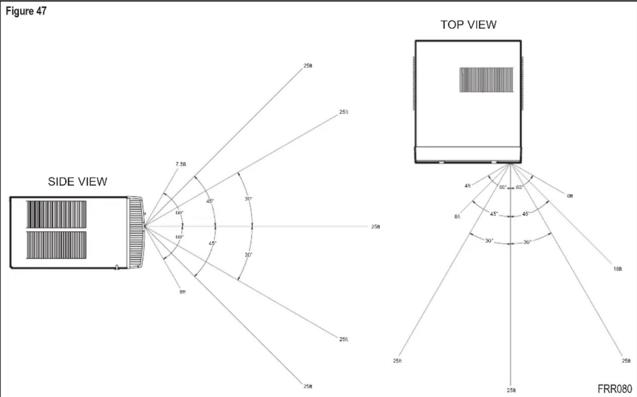
Remote Control - Refer to Figure 47 during operation description.
Getting Started - Install two (2) AAA batteries in the battery compartment located on the back of the unit.
Operation - The remote control should be within 25 feet of the air conditioner for operation. (Refer to Figure 47 for effectiveness). Press the power button to turn the remote on. The remote will automatically power off after 15 seconds if the buttons are not being pressed. The remote must be on to control the unit.
POWER Button - Turns remote and unit on and off.
SYSTEM Button - Allows the user to sequentially select the following: AUTO, COOL, HEAT, and FAN ONLY operations. When the button is pressed, the display indicates which mode has been selected via a display message. Note that when the heating function is not available, the system will automatically skip the HEAT mode.
FAN MODE Button - Selects between automatic (AUTO FAN) or CONTINUOUS operation. In the AUTO FAN mode, the fan only turns on and off when the compressor operates or the heat function is enabled.
NOTE: AUTO FAN is not available in the FAN ONLY Mode, the display indicates CONTINUOUS. In the CONTINUOUS mode, fan speed is determined by your selection on the FAN SPEED button.
FAN SPEED Button - Used to sequentially select new fan speed, plus AUTO operation. When the FAN SPEED button is pressed, the fan speed icon (triangle) changes to indicate the new speed level. Fan speed automatically varies depending on the set temperature on the control panel and the actual room temperature. For example, if there is a big difference between your set temperature and the actual room temperature, the system fan speed increases to HIGH. It remains at this speed until the room temperature matches the set temperature.
UP and DOWN Arrows - Pressing either the UP or DOWN button changes the desired room temperature. The factory preset lower and upper limits are 60 °F (16 °C) and 99 °F (37 °C). These buttons are also used to navigate between function options when using the User Menu or Maintenance Mode.
Remote Effectiveness
Handheld Remote - Has an operating range of up to 25 ft. The infrared remote control signal must have a clear path to transmit the command to the air conditioning unit. The remote signal has some ability to "bounce" off of walls and furniture similar to a television remote control. The diagram below shows the typical operating range of the control in a standard room with 8 ft high ceilings.
Airflow Selection and Adjustment
Airflow direction adjustment
The airflow path may be adjusted to distribute air independently from the left or right side of the discharge opening. Each of the banks of louvers can be directed left, right, up, or down in order to achieve the most optimum airflow positioning.
To adjust airflow direction, grab the lever in the center of the louver bank and move it in the direction that you would like the air to be directed. Please note that it is normal that airflow may be stronger out of one side of the louvers than the other.
Installation Instructions
READ THIS FIRST! Electrical Requirements

WARNING

Electrical Shock Hazard
Make sure your electrical receptacle has the same configuration as your air conditioner's plug. If different, consult a Licensed Electrician.
Do not use plug adapters.
Do not use an extension cord.
Do not remove ground prong.
Always plug into a grounded 3 prong outlet.
Failure to follow these instructions can result in death, fire, or electrical shock.
IMPORTANT: Before you begin the actual installation of your air conditioner, check your local electrical codes and the information below. Your air conditioner must be connected to a power source with the same alternating current (A.C.) voltage and amperage as marked on the name plate located on the chassis. Only A.C. can be used. Direct Current (D.C.) cannot be used.
CIRCUIT PROTECTION – Use on single outlet circuit only. An overloaded circuit will invariably cause malfunction or failure of an air conditioner; therefore, it is necessary that the electrical protection is adequate. Due to momentary high current demand when the air conditioner starts, use a "TIME DELAY" fuse or a HACR type circuit breaker. Consult your dealer or power company if in doubt.
Refer to the electrical name plate located on the air conditioner chassis (see Page 2) to determine the correct fuse or circuit breaker amperage for your model (see Table 1 on Page 5 for electrical receptacle types).
The power cord has a plug with a grounding prong and a matching receptacle is required.

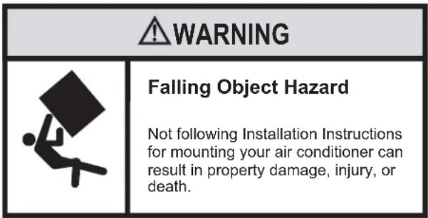
WARNING

natural_image
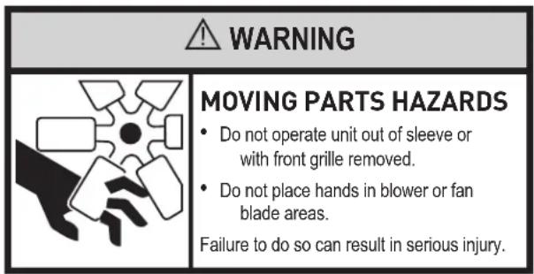
Abstract black-and-white graphic of a hand holding a fan with geometric shapes around it (no text or symbols)MOVING PARTS HAZARDS
- Do not operate unit out of sleeve or with front grille removed.
- Do not place hands in blower or fan blade areas.
Failure to do so can result in serious injury.

CAUTION

Excessive Weight Hazard
Use two or more people when installing your air conditioner.
Failure to do so can result in back or other injury.
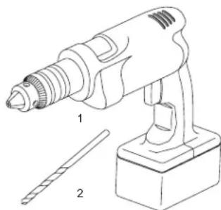
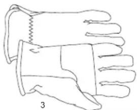
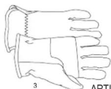
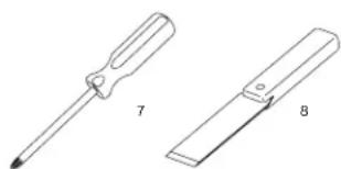
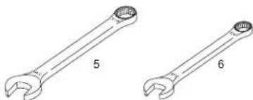
Recommended Tools
- Power Drill
- ^5/_32 " Drill Bit
- Gloves
- Carpenters Level
- ^5/_16 " Wrench
- ^1/4 " Wrench
-
2 Phillips Screw Driver
- Putty Knife or (wood stir stick)
natural_image
Line drawing of a handheld electric drill with two labeled parts (1 and 2), no text or symbols present.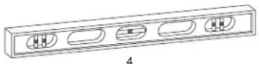
natural_image
Line drawing of a pair of gloves with a bandage, labeled '3' (no text or symbols on the gloves themselves)
natural_image
Two types of wrenches labeled 5 and 6, shown side by side without any text or symbols on the itself.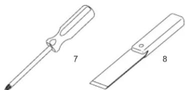
natural_image
Technical line drawings of two screwdriver tools labeled 7 and 8 (no text or symbols on the devices themselves)ITEMS NOT TO SCALE
Installation Instructions for WSE Sleeve
(WSE Sleeve Accessory Sold Separately)
| Mounting Hardware | ||
| ITEMNO | DESCRIPTION QTY. | |
| 1 SCREW, #12A x 2" 7 | ||
Wall Preparation
STEP 1. The wall opening required for a WSE SLEEVE is 17 14 " high by 27 14 " wide.
STEP 2. LINTELS must be used in opening of brick veneer and masonry walls to support the material above the WSE SLEEVE. The following considerations should also be given:
A. Masonry walls to support the material above the WSE SLEEVE.
B. Adjustable SUBBASE (SB) or other unit support must be provided for panel wall type construction and for walls less than 8" thick.
Installation Instructions for WSE Sleeve continued
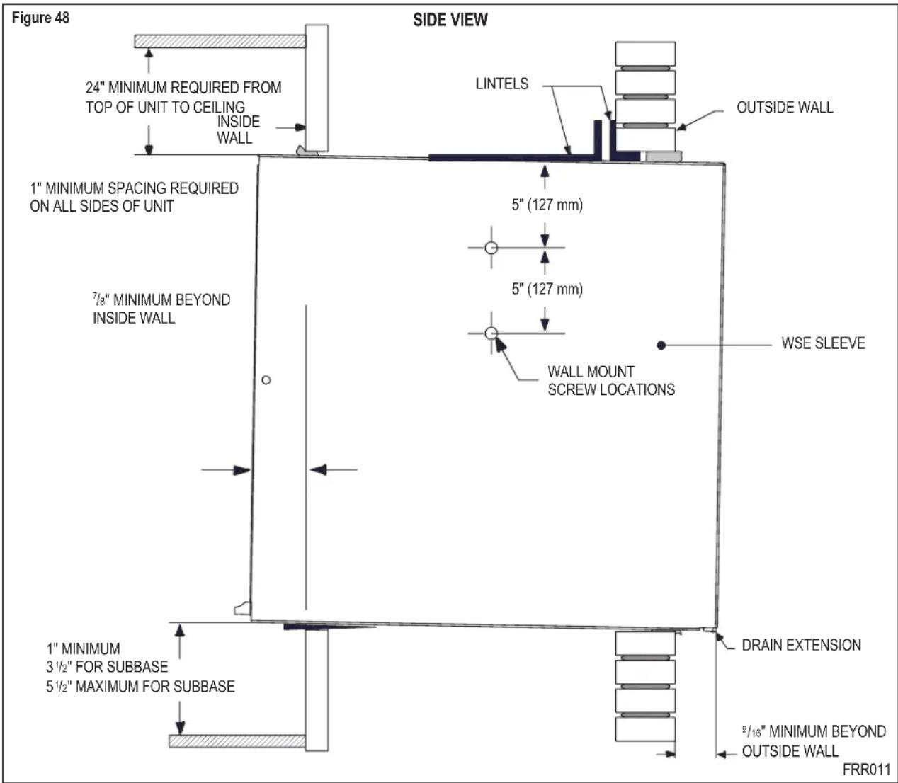
Installation Requirements
STEP 1. The WSE sleeve should be positioned so that the drain extension extends a minimum of 916 beyond the outside wall (see Figure 48).
STEP 2. The WSE sleeve must extend a minimum of 78 " beyond the inside wall.
STEP 3. The WSE sleeve must be installed level side to side.
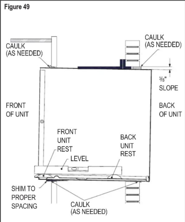
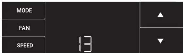
STEP 4. The WSE sleeve must also be installed with a downward tilt toward the outside of the building. If a level is placed so that it rests on the front and back unit rest as shown in Figure 49, a properly installed unit provides a 38 " slope to the outside of the building.
NOTICE
Sleeve projections and leveling precautions must be observed to prevent the entry of water into the room.
Sleeve Requirements
STEP 1. After unpacking the WSE sleeve from the carton, remove the indoor weather panel. Place the WSE sleeve in the wall opening following the instructions given in the Installation Requirements. Attach the sleeve to the inside wall by driving two #12A x 2" screws in each side of the sleeve (see Figure 50). Shim at the top of the sleeve, midway between the sides. Drive one #12A x 2" screw in the top of the sleeve. If the wall opening is not framed with wood, use expansion anchor bolts or molly (toggle) bolts (not provided).
STEP 2. Once the sleeve has been installed, check the level again to be sure the 38 " downward slope is maintained.
NOTE: If necessary, apply shims below the chassis and inside the sleeve front unit rest, to ensure a 38 " downward slope front to back.
STEP 3. Caulk the perimeter of the entire opening on the inside and the outside between the sleeve and the wall.
STEP 4. The indoor weather panel removed in Step 1 above must be remounted back in place if masonry work is to be done and/or if the "WallMaster" chassis is to be installed at a later date.
How to cover inner weather panel holes
Two beige plugs are included in the plastic bag taped to the WallMaster chassis. These plugs may be used to cover the two holes left after removing the indoor weather panel.
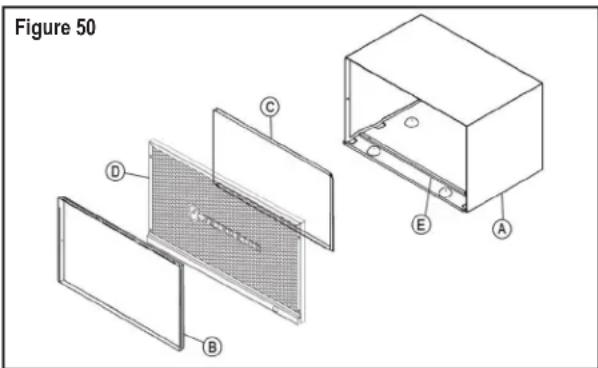
| A | WSE SLEEVE |
| B 6 | 1603200 INDOOR WEATHER PANEL (METAL) |
| C 6 | 1603304 OUTDOOR WEATHER PANEL (PAINTED METAL) |
| D 6 | 1603012 ASSY GRILLE WSE SLEEVE |
| E 6 | 1578101 GASKET (ATTACHED TO SLEEVE) |
WallMaster Chassis Installation Instructions
for WCT, WET and WHT models
| CAUTION | |
 | Excessive Weight HazardUse two or more people when installing your air conditioner.Failure to do so can result in back or other injury. |
CAUTION

Cut/Sever
Although great care has been taken to minimize sharp edges in the construction of your unit, use gloves or other hand protection when handling unit Failure to do so can result in minor to moderate personal injury.
STEP 1. Check the sleeve to be certain it has been correctly installed in the wall. Remove the front panel on the WSE SLEEVE. Remove the rear WEATHER PANEL. Reverse grille. Place lower edge into sleeve tab (Friedrich logo facing out). Align slots with the screw holes. Secure grille with screws.
A. Check the anchor screw. There should be four (4) in the WSE SLEEVE (two in each side).
B. Determine if the sleeve has a downward slope of outside. See Page 26 for further details.
^3/_8 " to the
C. Check to be sure the sleeve has been sealed around all edges with an industrial type caulking on both the outside and inside to prevent rain entry.
STEP 3. Check the electrical receptacle to see that it conforms to the requirements for the chassis model to be installed. See Page 5 for the receptacle requirements.
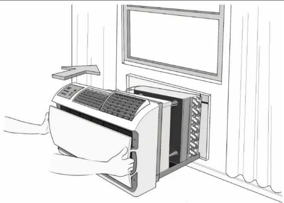
STEP 3. Remove the chassis from the shipping carton. Lift the chassis by the basepan and slide it into the front of the sleeve. (Obtain assistance as needed.) Push the chassis all the way into the sleeve, using the plastic front handles, so that the front panel meets the front edge of the shell.
NOTE: Chassis comes with pre-installed seal gasket.
Figure 51
natural_image
Line drawing of a person using an air conditioner to clean the oven, with a window view on the wall (no text or symbols)WallMaster Chassis Installation Instructions
for WCT, WET and WHT models
Condensate Removal
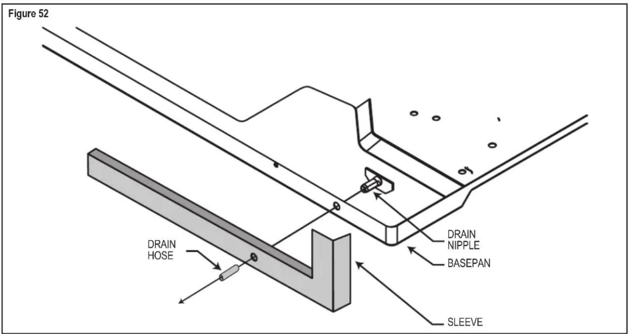
If you desire to drain condensate from the basepan during unit operation, this unit is provided with a drain nipple that can be attached to the basepan. You must provide a 38 " outside diameter thin-wall plastic or copper tube which will attach to the drain nipple.
Follow the instructions below:
STEP 1. Find the drain rubber plug on the rear of the basepan and remove it (see Figure 52).
STEP 2. Remove the knockout in the lower right side of the rear grille. Slide the chassis into the WSE SLEEVE so that the drain nipple extends through the knockout.
STEP 3. Slide the tubing over the drain nipple. If the chassis must be removed from the sleeve for service, remove the clamped drain hose before sliding the chassis out of the sleeve.
| WARNING | |
| MOVING OBJECT HAZARD Replace all panels before operating your air conditioner. Failure to do so can result in severe personal injury or death and damage to product or other property. | |
Alternate Drain Kits
DK (Drain Kit)
In the event that the outdoor temperature drops below 37 °F , any water that remains in the chassis basepan is drained into the sleeve pan on WET and WHT models to prevent freezing. (NOTE: In the cooling mode of the WCT, WET and WHT models, condensate overflow is possible in very humid climates). For these particular instances, an optional drain kit (Accessory #DK) is available for water removal.
IDK (Drain Kit)
New construction allowing for condensate drain systems built within the walls can use the Friedrich Interior Drain Kit (Accessory #IDK). This kit is designed for installation in the bottom of the sleeve below the condensate bellows valve (heat/ cool models only).
Troubleshooting Tips
| COMPLAINT CAUSE | SOLUTION | |
| Unit does not operate. | The unit is turned to the off position, or the thermostat is satisfied. | Turn the unit to the on position and raise or lower temperature setting (as appropriate) to call for operation. |
| The LCDI power cord is unplugged. | Plug into a properly grounded 3 prong receptacle.See "Electrical Rating Tables" on Page 5 for the proper receptacle type for your unit. | |
| The LCDI power cord has tripped (Reset button has popped out). | Press and release RESET (Listen for click. Reset button latches and remains in.) to resume operation. | |
| The circuit breaker has tripped or the supply circuit fuse has blown. | Reset the circuit breaker, or replace the fuse as applicable. If the problem continues, contact a licensed electrician. | |
| There has been a local power failure. | The unit will resume normal operation once power has been restored. | |
| Unit Trips Circuit Breaker or Blows Fuses. | Other appliances are being used on the same circuit. | The unit requires a dedicated outlet circuit, not shared with other appliances. |
| An extension cord is being used. | Do NOT use an extension cord with this or any other air conditioner. | |
| The circuit breaker or time-delay fuse is not of the proper rating. | Replace with a circuit breaker or time-delay fuse of the proper rating. See "Electrical Rating Tables" on Page 5 for the proper circuit breaker/ fuse rating for your unit. If the problem continues, contact a licensed electrician. | |
| LCDI Power Cord Trips (Reset Button Pops Out). | The LCDI power cord can trip (Reset button pops out) due to disturbances on your power supply line. | Press and release RESET (Listen for click. Reset button latches and remains in.) to resume normal operation. |
| Electrical overload, overheating, or cord pinching can trip (Reset button pops out) the LCDI power cord. | Once the problem has been determined and corrected, press and release RESET (Listen for click. Reset button latches and remains in.) to resume normal operation. | |
| NOTE: A damaged power supply cord must be replaced with a new power supply cord obtained from the product manufacturer and must not be repaired. | ||
| Unit Does Not Cool/ Heat Room Sufficiently, or Cycles On And Off Too Frequently. | The return/ discharge air grille is blocked. | Ensure that the return and/ or discharge air paths are not blocked by curtains, blinds, furniture, etc. |
| Windows or doors to the outside are open. | Ensure that all windows and doors are closed. | |
| The temperature is not set at a cool enough/ warm enough setting. | Adjust the Temperature control to a cooler or warmer setting as necessary. | |
| The filter is dirty or obstructed. | Clean the filter, (See Routine Maintenance), or remove obstruction. | |
| The indoor coil or outdoor coil is dirty or obstructed. | Clean the coils, (See Routine Maintenance), or remove obstruction. | |
| There is excessive heat or moisture (cooking, showers, etc.) in the room. | Be sure to use exhaust vent fans while cooking or bathing and, if possible, try not to use heat producing appliances during the hottest part of the day. | |
| The temperature of the room you are trying to cool is extremely hot. | Allow additional time for the air conditioner to cool off a very hot room. | |
Troubleshooting Tips continued
| COMPLAINT CAUSE | SOLUTION | |
| Unit Does Not Cool/ Heat Room Sufficiently, or Cycles On And Off Too Frequently (continued). | The outside temperature is below 60 °F (16°C). | Do not try to operate your air conditioner in the cooling mode when the outside temperature is below 60 °F (16°C). The unit will not cool properly, and the unit may be damaged. |
| The digital control is set to fan cycling mode. | Since the fan does not circulate the room air continuously at this setting, the room air does not mix as well and hot (or cold) spots may result. Using the continuous fan setting is recommended to obtain optimum comfort levels. | |
| The air conditioner has insufficient cooling capacity to match the heat gain of the room. | Check the cooling capacity of your unit to ensure it is properly sized for the room in which it is installed. Room air conditioners are not designed to cool multiple rooms. | |
| The air conditioner has insufficient heating capacity to match the heat loss of the room. | Check the heating capacity of your unit. Air conditioners are sized to meet the cooling load, and heater size is then selected to meet the heating load. In extreme northern climates, room air conditioners may not be able to be used as a primary source of heat. | |
| Unit Runs Too Much. | This may be due to an excessive heat load in the room. | If there are heat producing appliances in use in the room, or if the room is heavily occupied, the unit will need to run longer to remove the additional heat. |
| It may also be due to an improperly sized unit. | Be sure to use exhaust vent fans while cooking or bathing and, if possible, try not to use heat producing appliances during the hottest part of the day. | |
| This may be normal for higher efficiency (EER) air conditioners. | The use of higher efficiency components in your new air conditioner may result in the unit running longer than you feel it should. This may be more apparent, if it replaced an older, less efficient, model. The actual energy usage, however, will be significantly less when compared to older models. | |
| You may notice that the discharge air temperature of your new air conditioner may not seem as cold as you may be accustomed to from older units. This does not; however, indicate a reduction in the cooling capacity of the unit. | The energy efficiency ratio (EER) and cooling capacity rating (Btu/h) listed on the unit's rating plate are both agency certified. |

FRIEDRICH
Friedrich Air Conditioning Company
10001 Reunion Place, Suite 500
San Antonio, TX 78216
1-800-541-6645
www.friedrich.com
WALLMASTER® THRU-THE-WALL AIR CONDITIONERS
LIMITED WARRANTY
FIRST YEAR
ANY PART: If any part supplied by FRIEDRICH fails because of a defect in workmanship or material within twelve months from date of original purchase, FRIEDRICH will repair the product at no charge, provided room air conditioner is reasonably accessible for service. Any additional labor cost for removing inaccessible units and/or charges for mileage related to travel by a Service Agency that exceeds 25 miles one way will be the responsibility of the owner. This remedy is expressly agreed to be the exclusive remedy within twelve months from the date of the original purchase.
SECOND THROUGH FIFTH YEAR
SEALED REFRIGERANT SYSTEM: If the Sealed Refrigeration System (defined for this purpose as the compressor, condenser coil, evaporator coil, reversing valve, check valve, capillary, filter drier, and all interconnecting tubing) supplied by FRIEDRICH in your Room Air Conditioner fails because of a defect in workmanship or material within sixty months from date of purchase, FRIEDRICH will pay a labor allowance and parts necessary to repair the Sealed Refrigeration System; PROVIDED FRIEDRICH will not pay the cost of diagnosis of the problem, removal, freight charges, and transportation of the air conditioner to and from the Service Agency, and the reinstallation charges associated with repair of the Sealed Refrigeration System. All such cost will be the sole responsibility of the owner. This remedy is expressly agreed to be the exclusive remedy within sixty months from the date of the original purchase.
APPLICABILITY AND LIMITATIONS: This warranty is applicable only to units retained within the Fifty States of the U.S.A., District of Columbia, and Canada. This warranty is not applicable to:
- Air filters or fuses.
- Products on which the model and serial numbers have been removed.
- Products which have defects or damage which results from improper installation, wiring, electrical current characteristics, or maintenance; or caused by accident, misuse or abuse, fire, flood, alterations and/or misapplication of the product and/or units installed in a corrosive atmosphere, default or delay in performance caused by war, government restrictions or restraints, strikes, material shortages beyond the control of FRIEDRICH, or acts of God.
OBTAINING WARRANTY PERFORMANCE: Service will be provided by the FRIEDRICH Authorized Dealer or Service Organization in your area. They are listed in the Yellow Pages. If assistance is required in obtaining warranty performance, write to: Room Air Conditioner Service Manager, Friedrich Air Conditioning Co.
LIMITATIONS: THIS WARRANTY IS GIVEN IN LIEU OF ALL OTHER WARRANTIES. Anything in the warranty notwithstanding, ANY IMPLIED WARRANTIES OF FITNESS FOR PARTICULAR PURPOSE AND/OR MERCHANTABILITY SHALL BE LIMITED TO THE DURATION OF THIS EXPRESS WARRANTY. MANUFACTURER EXPRESSLY DISCLAIMS AND EXCLUDES ANY LIABILITY FOR CONSEQUENTIAL OR INCIDENTAL DAMAGE FOR BREACH OF ANY EXPRESSED OR IMPLIED WARRANTY.
NOTE: Some states do not allow limitations on how long an implied warranty lasts, or do not allow the limitation or exclusion of consequential or incidental damages, so the foregoing exclusions and limitations may not apply to you.
OTHER: This warranty gives you specific legal rights, and you may also have other rights which vary from state to state.
PROOF OF PURCHASE: Owner must provide proof of purchase in order to receive any warranty related services.
All service calls for explaining the operation of this product will be the sole responsibility of the consumer.
All warranty service must be provided by an Authorized FRIEDRICH Service Agency, unless authorized by FRIEDRICH prior to repairs being made.

FRIEDRICH
Friedrich Air Conditioning Co.
10001 Reunion Place, Suite 500 • San Antonio, Texas 78216
1-800-541-6645
www.friedrich.com

FRIEDRICH
natural_image
Line drawing of a white air conditioner unit with control panel and ventilation grille (no text or symbols)Do not remove, disable or bypass this unit's safety devices. Doing so may cause fire, Doing so may cause fire, injuries, or death.
natural_image
Line drawing of an air conditioner unit mounted on a wall, with a window and curtain in the background (no text or symbols)MENU
Figure 27

MENU
MENU
Figure 31


other
| Panel | Metric | Value | |---|---|---| | Figure 32 | MODE | 10.00 | | Figure 32 | FAN | ▲ | | Figure 32 | SPEED | ▼ | | Figure 33 | MENU | ● ● | | Figure 33 | MODE | 12.00 | | Figure 33 | FAN | ▲ | | Figure 33 | SPEED | ▼ | | Figure 34 | MENU | ● ● | | Figure 34 | MODE | 12.30 | | Figure 34 | FAN | ▲ | | Figure 34 | SPEED | ▼ | | Figure 35 | MENU | ● ● | | Figure 35 | MODE | 12.34 | | Figure 35 | FAN | ▲ | | Figure 35 | SPEED | ▼ | → MENUnatural_image
Line drawing of a white air conditioner unit with control panel and ventilation grille (no text or symbols)natural_image
Abstract black-and-white graphic of a hand holding a device with five circular components (no text or symbols)natural_image
Line drawing of a handheld electric drill with two labeled parts (1 and 2), no text or symbols present.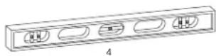
natural_image
Line drawing of a pair of gloves with textured soles, labeled 'ARTI' at bottom (no other text or symbols)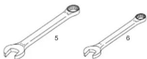
natural_image
Two technical line drawings of screwdrivers, labeled 7 and 8 (no text or symbols on the diagrams)natural_image
Line drawing of a person opening a wall-mounted air conditioner unit, with no visible text or symbols.natural_image
Black and white icon depicting a hand holding a device with five blades (no text or symbols)Friedrich Air Conditioning Company
10001 Reunion Place, Suite 500
San Antonio, TX 78216
1-800-541-6645
www.friedrich.com
GARANTIE LIMITÉE
WALLMASTER® À TRAVERS LE CLIMATISEUR
PREMIÈRE ANNÉE
Friedrich Air Conditioning Co.
10001 Reunion Place, Suite 500 • San Antonio, Texas 78216
1-800-541-6645
www.friedrich.com
FRIEDRICH
natural_image
Line drawing of a white air conditioner unit with control panel and ventilation grille (no text or symbols)Do not remove, disable or bypass this unit's safety devices. Doing so may cause fire, Doing so may cause fire, injuries, or death.
natural_image
Line drawing of an air conditioner unit mounted on a wall, with a window and fan in the background (no text or symbols)MENU
Figura 27
MENU
MENU
Figura 31


Figura 44

natural_image
Line drawing of a white air conditioner unit with control panel and ventilation grille (no text or symbols)natural_image
Abstract black-and-white graphic of a hand holding a device with five rectangular components (no text or symbols)natural_image
Line drawing of a handheld electric drill with two labeled parts (1 and 2), no text or symbols present.
natural_image
Two wrench illustrations labeled 5 and 6, shown side by side without any text or symbols on the tools themselves.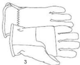
natural_image
Line drawing of a pair of gloves with one sleeve and the other in a pair, labeled '3' (no text or symbols on the gloves themselves)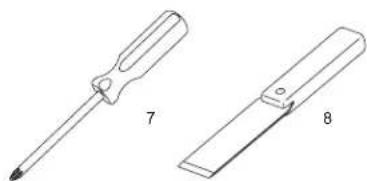
natural_image
Technical line drawings of two screwdriver tools labeled 7 and 8 (no text or symbols on the tools themselves)natural_image
Line drawing of a person using an air conditioner to clean the interior (no text or symbols)natural_image
Black and white icon showing a hand holding a valve with multiple blades (no text or symbols)Friedrich Air Conditioning Company
10001 Reunion Place, Suite 500
San Antonio, TX 78216
1-800-541-6645
www.friedrich.com
Friedrich Air Conditioning Co.
10001 Reunion Place, Suite 500 • San Antonio, Texas 78216
1-800-541-6645
www.friedrich.com