
PLH 28 XE - Drill MILWAUKEE - Free user manual and instructions
Find the device manual for free PLH 28 XE MILWAUKEE in PDF.

| Product type | Rotary hammer |
| Brand | Milwaukee |
| Model | PLH 28 XE |
| Rated power input | 800 W |
| Power output | 400 W |
| No-load speed | 0-1500 min⁻¹ |
| Max. load speed | 0-1000 min⁻¹ |
| Max. impact drilling speed | 0-4000 min⁻¹ |
| Impact energy (EPTA 05/2009) | 4.1 J |
| Drilling diameter in concrete | 28 mm |
| Drilling diameter in steel | 13 mm |
| Drilling diameter in wood | 40 mm |
| Impact drill crown (bricks) | 82 mm |
| Clamping collar diameter | 54 mm |
| Weight (EPTA 01/2014) | 3.6 kg |
| Sound pressure level (K=3 dB(A)) | 90.5 dB(A) |
| Sound power level (K=3 dB(A)) | 101.8 dB(A) |
| Protection class | II (double insulation) |
| Power supply | Single-phase, 220-230 V (110-120 V depending on version) |
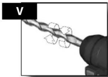
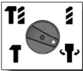
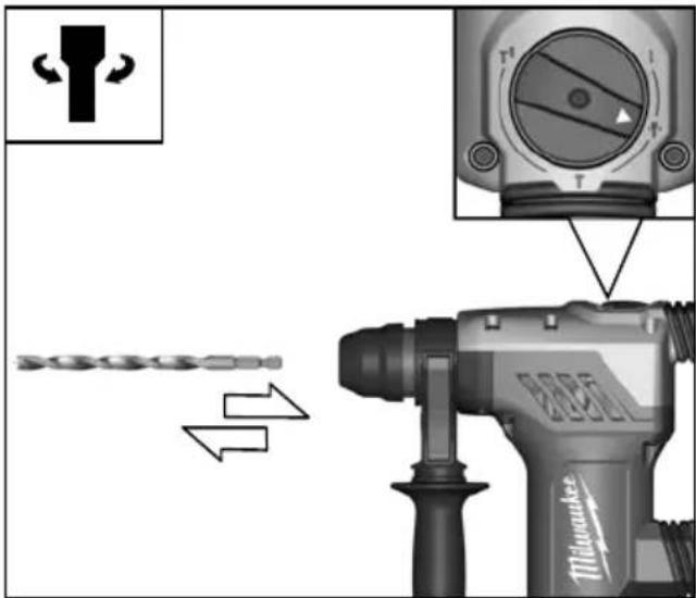
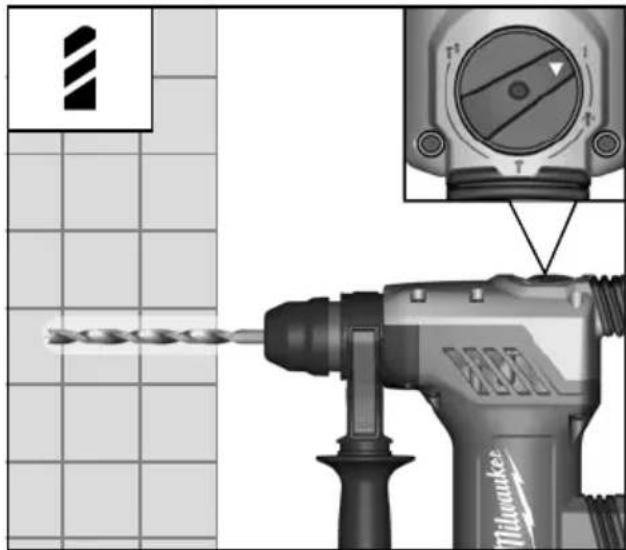
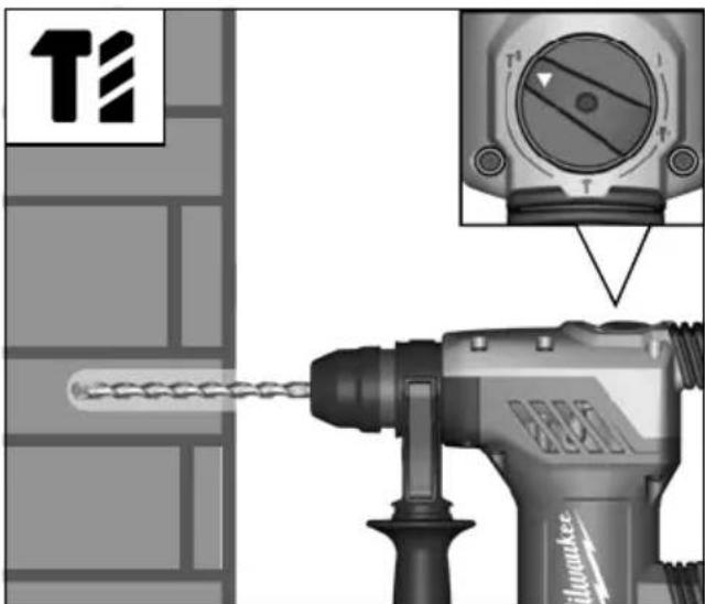
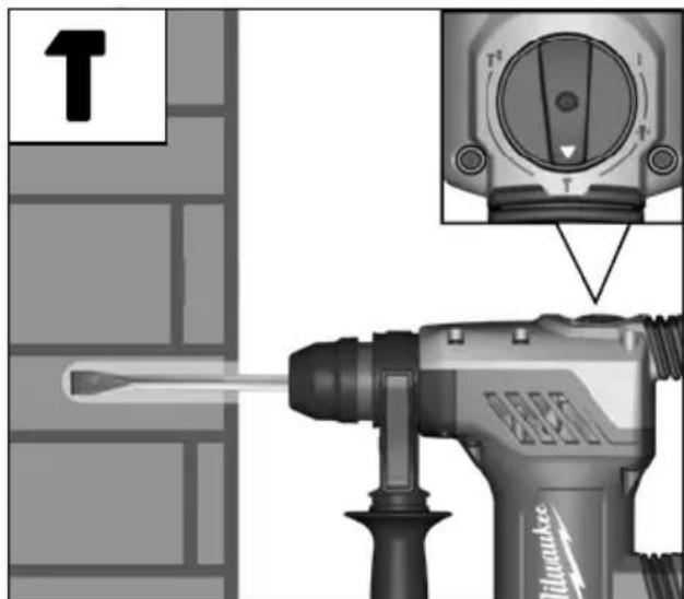
| Main functions | Impact drilling, chiselling, drilling without impact |
| Maintenance and cleaning | Clean ventilation slots; replace carbon brushes at an authorized service center |
| Safety | Wear hearing protection, goggles, dust mask; use auxiliary handle |
| Spare parts and repairability | Milwaukee accessories and spare parts available at service centers |
| General information | Complies with directives 2011/65/EU, 2006/42/EC, 2014/30/EU; standards EN 60745, EN 55014, etc. |
| Intended use | Impact drilling in masonry/concrete, chiselling, drilling in wood, metal, plastic |
Frequently Asked Questions - PLH 28 XE MILWAUKEE
User questions about PLH 28 XE MILWAUKEE
0 question about this device. Answer the ones you know or ask your own.
Ask a new question about this device
Download the instructions for your Drill in PDF format for free! Find your manual PLH 28 XE - MILWAUKEE and take your electronic device back in hand. On this page are published all the documents necessary for the use of your device. PLH 28 XE by MILWAUKEE.
USER MANUAL PLH 28 XE MILWAUKEE
natural_image
Black-and-white photo of a Milwaukee electric drill put tool (no visible text or symbols on the device body)PLH 28 E
PLH 28 XE
Original instructions
natural_image
Exterior view of a Milwaukee electric drill putter (no text or symbols visible on the device body)
natural_image
Close-up of a tool tip interacting with a mechanical component, showing motion arrows (no text or symbols)
natural_image
Close-up of a mechanical component with a directional arrow indicating motion (no visible text or symbols)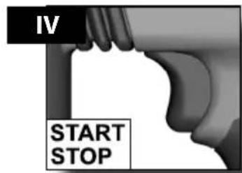
natural_image
Close-up of a mechanical component with a coiled wire and directional arrows indicating rotation (no text or symbols)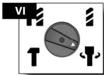

PLH 28 XE

natural_image
Mechanical component diagram showing two parts with arrows indicating motion, no text or symbols present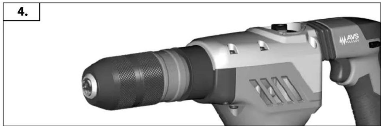
natural_image
Close-up of a black-and-white photo of a Siemens AAVS electric drill with visible model number 13011 (no text or symbols on the device itself)
PLH 28 XE

natural_image
Close-up of a tool tip interacting with a mechanical component, showing two curved arrows indicating motion (no text or symbols present)PLH 28 E

natural_image
Technical illustration of a drill bit and drill bit with directional arrows indicating movement (no text or symbols)
natural_image
Blank gray image with no visible content, text, or symbols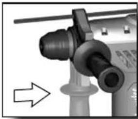
natural_image
Close-up of a mechanical component with a bolt and cylindrical shaft, no visible text or symbols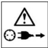
natural_image
Close-up of a mechanical tool interacting with a cylindrical component, showing a shaft and handle assembly (no text or symbols visible)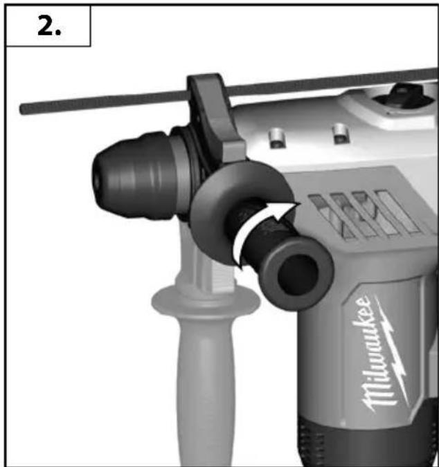
natural_image
Close-up of a Milwaukee drill bit with handle and screwdriver (no visible text or symbols)
natural_image
3D rendering of a mechanical component with an arrow indicating direction, showing a bent edge and a small inset image of a rabbit (no text or symbols)
natural_image
Close-up of a mechanical component with a coiled wire and threaded shaft (no visible text or symbols)

| TECHNICAL DATARotary Hammer | PLH 28 E220-230 V | PLH 28 XE220-230 V | PLH 28 XE110-120 V |
| Production code 4467 91 04... | 4520 81 04... ... 000001-999999 | 4468 01 04... 4468 21 04... 4520 90 04... 4520 95 04... ... 000001-999999 | 4468 26 04... 4520 99 04... ... 000001-999999 |
| Rated input 800 W 800 W 800 W | |||
| Output 400 W 400 W 400 W | |||
| No-load speed 0-1500 min | -1 | 0-1500 min^-1 | 0-1500 min^-1 |
| Speed under load max. 0-1000 min | -1 | 0-1000 min^-1 | 0-1000 min^-1 |
| Rate of percussion under load max. 0-4000 min | -1 | 0-4000 min^-1 | 0-4000 min^-1 |
| Impact energy per stroke according to EPTA-Procedure 05/2009 4,1 J 4,1 J 4,1 J | |||
| Drilling capacity in concrete 28 mm 28 mm 28 mmDrilling capacity in steel 13 mm 13 mm 13 mmDrilling capacity in wood 40 mm 40 mm 40 mmLight core cutter in bricks and limestone 82 mm 82 mm 82 mm | |||
| Chuck neck diameter | 54 mm 54 mm 54 mm | ||
| Weight according EPTA-Procedure 01/2014 | 3,4 kg | 3,6 kg | 3,6 kg |
| Noise informationMeasured values determined according to EN 60745. Typically, the A-weighted noise levels of the tool are: | |||
| Sound pressure level (Uncertainty K=3dB(A)) | 90,5 dB (A) | 90,5 dB (A) | 90,5 dB (A) |
| Sound power level (Uncertainty K=3dB(A)) | 101,8 dB (A) | 101,8 dB (A) | 101,8 dB (A) |
| Wear ear protectors! | |||
| Vibration informationVibration total values (triaxial vector sum) determined according to EN 60745Hammer-drilling into concrete:Vibration emission value a_h,HD Uncertainty K=Chiselling:Vibration emission value a_h,Cheq Uncertainty K= | 10,6 m/s^2 1,5 m/s^2 6,81 m/s^2 1,5 m/s^2 | 10,6 m/s^2 1,5 m/s^2 6,81 m/s^2 1,5 m/s^2 | 10,6 m/s^2 1,5 m/s^2 6,81 m/s^2 1,5 m/s^2 |
WARNING!
The vibration emission level given in this information sheet has been measured in accordance with a standardised test given in EN 60745 and may be used to compare one tool with another. It may be used for a preliminary assessment of exposure.
The declared vibration emission level represents the main applications of the tool. However if the tool is used for different applications, with different accessories or poorly maintained, the vibration emission may differ. This may significantly increase the exposure level over the total working period.
An estimation of the level of exposure to vibration should also take into account the times when the tool is switched off or when it is running but not actually doing the job. This may significantly reduce the exposure level over the total working period.
Identify additional safety measures to protect the operator from the effects of vibration such as: maintain the tool and the accessories, keep the hands warm, organisation of work patterns.

WARNING
Read all safety warnings and all instructions. Failure to follow the warnings and instructions may result in electric shock, fire and/or serious injury.
Save all warnings and instructions for future reference.
HAMMER SAFETY WARNINGS
We are protectors. Exposure to noise can cause hearing loss.
Use auxiliary handle(s), if supplied with the tool. Loss of control can cause personal injury.
Hold power tool by insulated gripping surfaces, when performing an operation where the cutting accessory may contact hidden wiring or its own cord. Cutting accessory contacting a "live" wire may make exposed metal parts of the power tool "live" and could give the operator an electric shock.
Additional Safety and Working Instructions
Use protective equipment. Always wear safety glasses when working with the machine. The use of protective clothing is recommended, such as dust mask, protective gloves, sturdy non-slip footwear, helmet and ear defenders.
The dust produced when using this tool may be harmful to health. Do not inhale the dust. Use a dust absorption system and wear a suitable dust protection mask. Remove deposited dust thoroughly, e.g. with a vacuum cleaner.
Keep mains lead clear from working range of the machine. Always lead the cable away behind you.
Do not machine any materials that present a danger to health (e.g. asbestos).
When working in walls ceiling, or floor, take care to avoid electric cables and gas or waterpipes.


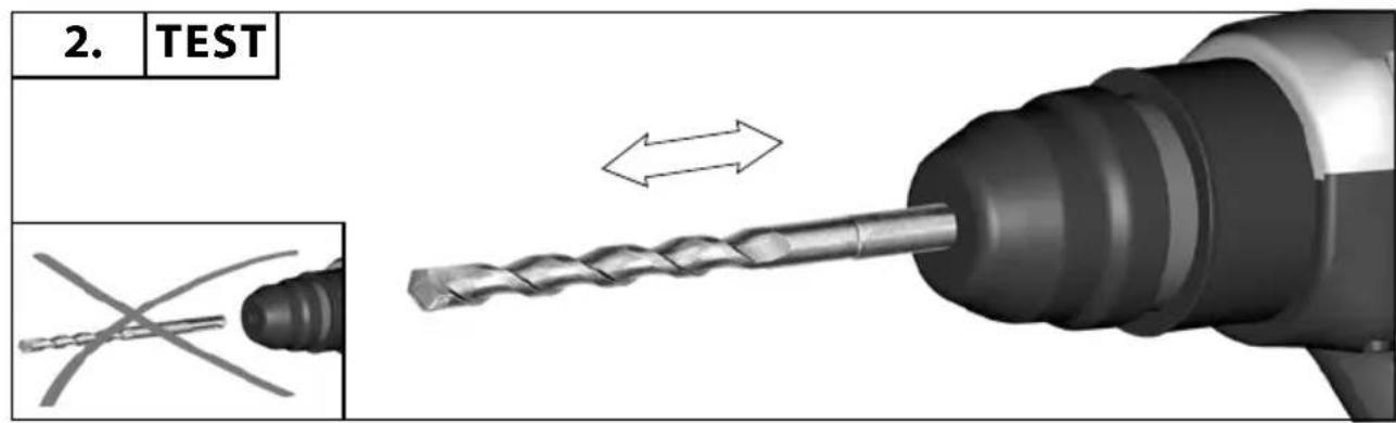
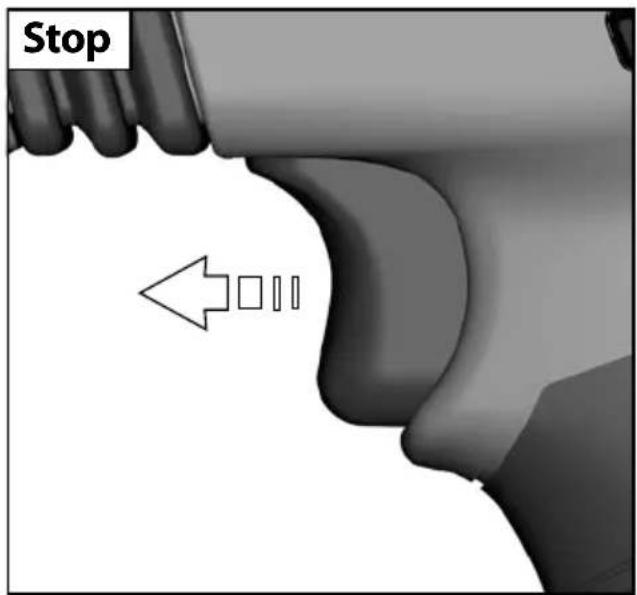
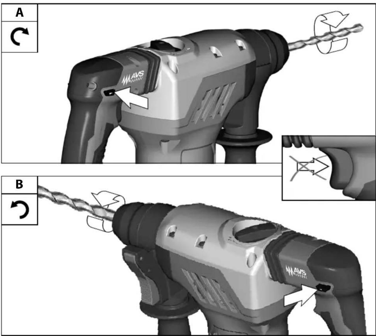
Switch the device off immediately if the insertion tool stalls! Do not switch the device on again while the insertion tool is stalled, as doing so could trigger a sudden recoil with a high reactive force. Determine why the insertion tool stalled and rectify this, paying heed to the safety instructions.
Possible causes can be:
- it is tilted in the workpiece to be machined
- breakage of the material to be used
• the power tool is overloaded
Do not reach into the machine while it is running.
The insertion tool may become hot during use.
WARNING! Danger of burns
- when changing tools
- when setting the device down
Chips and splinters must not be removed while the machine is running.
Clamp your workpiece with a clamping device. Unclamped workpieces can cause severe injury and damage.
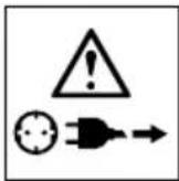
Always disconnect the plug from the socket before carrying out any work on the machine.
OPERATION
Cold Starting
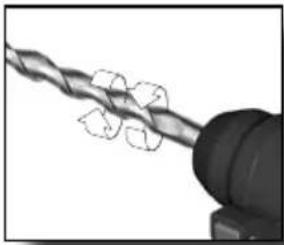
If this tool is stored for a long period of time or at cold temperatures, it may not hammer initially because the lubrication has become stiff.
To warm up the tool
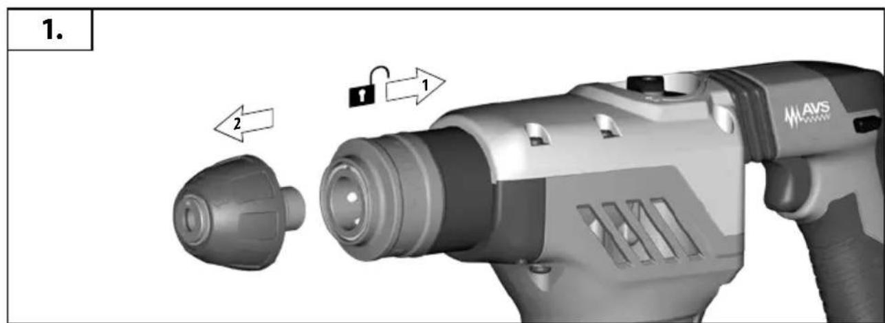
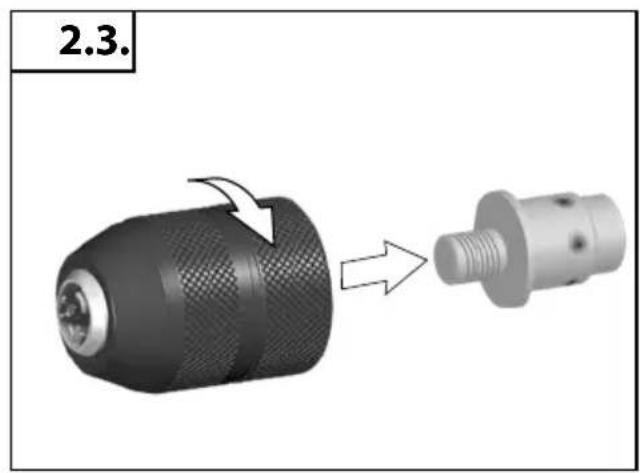
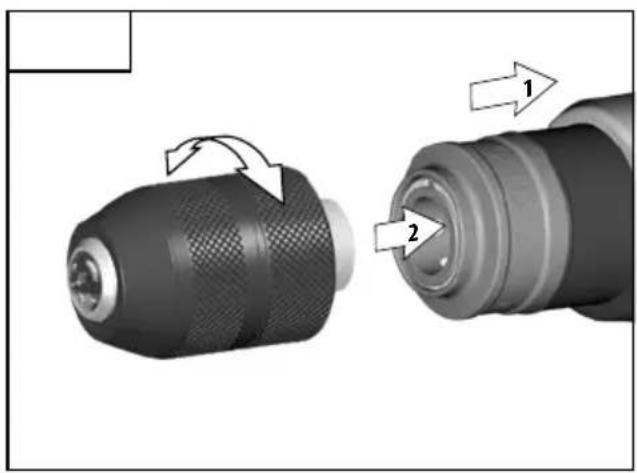
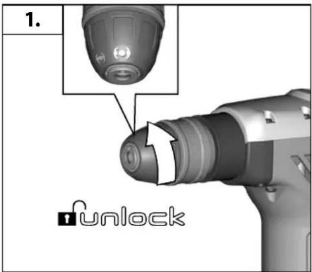
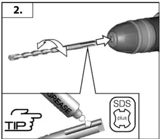
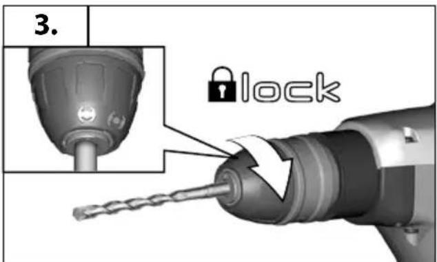
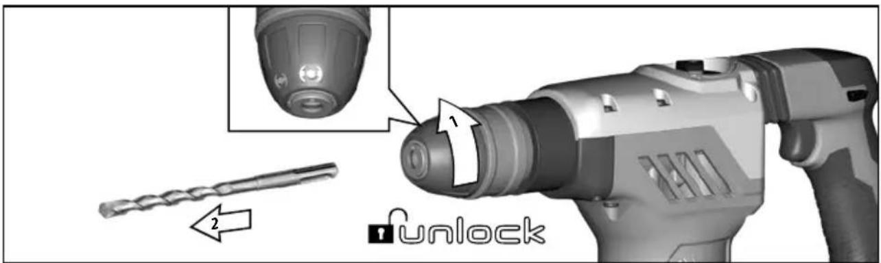
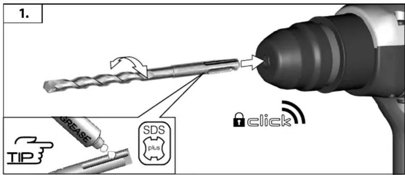
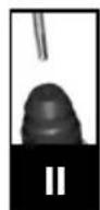
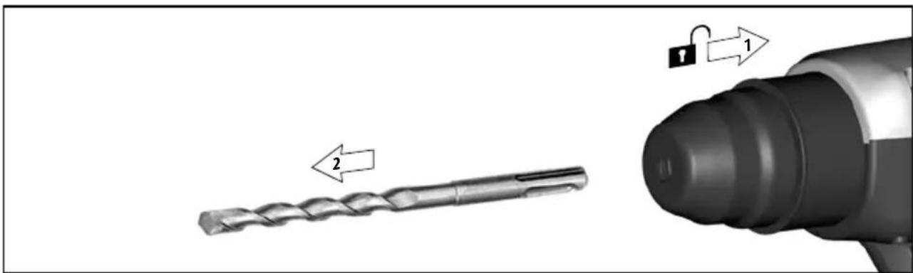
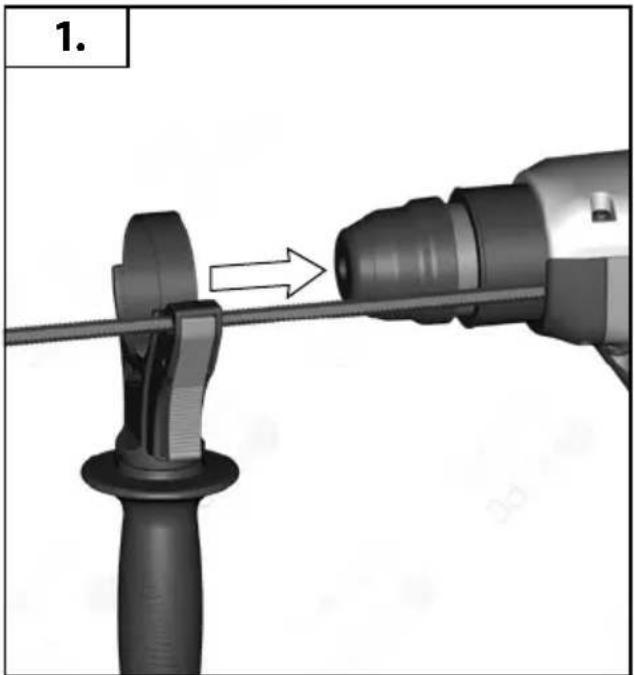
- Insert and lock a bit or chisel into the tool.
- Pull the trigger and apply force to the bit or chisel against a concrete or wood surface for a few seconds. Release the trigger.
- Repeat until the tool starts hammering. The colder the tool is, the longer it will take to warm up.
MAINS CONNECTION
Connect only to single-phase AC system voltage as indicated on the rating plate. It is also possible to connect to sockets without an earthing contact as the design conforms to safety class II.
Appliances used at many different locations including wet room and open air must be connected via a residual current device (FI, RCD, PRCD) of 30mA or less.
Only plug-in when machine is switched off.
Under the effect of extreme electromagnetic interferences from the outside, temporary variations in the speed of rotation could arise in particular cases.
SPECIFIED CONDITIONS OF USE
The rotary pneumatic hammer can be used for hammer drilling, chiselling in stone and concrete and drilling in wood, metal as well as plastic.
MAINTENANCE
The ventilation slots of the machine must be kept clear at all times.
If the supply cord of this appliance is damaged, it must only be replaced by a repair shop appointed by the manufacturer, to avoid hazardous situations.
Important note! If the carbon brushes are worn, in addition to exchanging the brushes the tool should be sent to after-sales service. This will ensure long service life and top performance.
Use only Milwaukee accessories and Milwaukee spare parts. Should components need to be replaced which have not been described, please contact one of our Milwaukee service agents (see our list of guarantee/service addresses).
If needed, an exploded view of the tool can be ordered. Please state the Article No. as well as the machine type printed on the label and order the drawing at your local service agents or directly at: Techtronic Industries GmbH, Max-Eyth-Straße 10, 71364 Winnenden, Germany.
EC-DECLARATION OF CONFORMITY
We declare under our sole responsibility that the product described under "Technical Data" fulfills all the relevant provisions of the directives
2011/65/EU (RoHS)
2006/42/EC
2014/30/EU
and the following harmonized standards have been used.
EN 60745-1:2009+A11:2010
EN 60745-2-6:2010
EN 55014-1:2017+A11:2020
EN 55014-2:2015
EN 61000-3-2:2014
EN 61000-3-3:2013
EN IEC 63000:2018

Winnenden, 2020-11-30

Alexander Krug / Managing Director
Authorized to compile the technical file
Techtronic Industries GmbH
Max-Eyth-Straße 10, 71364 Winnenden, Germany
GB-DECLARATION OF CONFORMITY
We declare as the manufacturer under our sole responsibility that the product described under „Technical Data“ fulfills all the relevant provisions of the following Regulations
S.I. 2012/3032 (as amended), S.I. 2008/1597 (as amended),
S.I. 2016/1091 (as amended) and that the following designated standards have been used:
BS EN 60745-1:2009+A11:2010
BS EN 60745-2-6:2010
BS EN 55014-1:2017+A11:2020
BS EN 55014-2:2015
BS EN 61000-3-2:2014
BS EN 61000-3-3:2013
BS EN IEC 63000:2018
Winnenden, 2020-11-30

Alexander Krug / Managing Director
Authorized to compile the technical file
Techtronic Industries GmbH
Max-Eyth-Straße 10, 71364 Winnenden, Germany
English
SYMBOLS

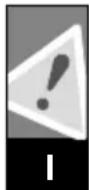
CAUTION! WARNING! DANGER!

Please read the instructions carefully before starting the machine.
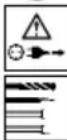
Always disconnect the plug from the socket before carrying out any work on the machine.
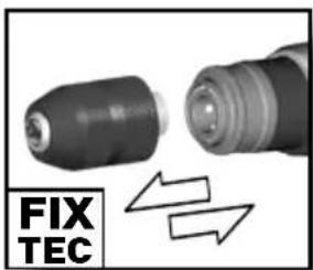
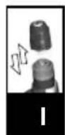
Accessory - Not included in standard equipment, available as an accessory.

Do not dispose of electric tools together with household waste material. Electric tools and electronic equipment that have reached the end of their life must be collected separately and returned to an environmentally compatible recycling facility. Check with your local authority or retailer for recycling advice and collection point.

Class II tool. Tool in which protection against electric shock does not rely on basic insulation only, but in which additional safety precautions, such as double insulation or reinforced insulation, are provided. There being no provision for protective earthing or reliance upon installation conditions.

European Conformity Mark

British Conformity Mark

Ukraine Conformity Mark

EurAsian Conformity Mark


Winnenden, 2020-11-30

Alexander Krug / Managing Director
Max-Eyth-Straße 10, 71364 Winnenden, Germany

SYMBOLE

DÉCLARATION CE DE CONFORMITÉ
Winnenden, 2020-11-30
Alexander Krug / Managing Director
Max-Eyth-Straße 10, 71364 Winnenden, Germany
Français
SYMBOLES

ATTENTION! AVERTISSEMENT! DANGER!

Winnenden, 2020-11-30
Alexander Krug / Managing Director
Max-Eyth-Straße 10, 71364 Winnenden, Germany
SIMBOLI

ATTENZIONE! AVVERTENZA! PERICOLO!

Winnenden, 2020-11-30

Alexander Krug / Managing Director
Max-Eyth-Straße 10, 71364 Winnenden, Germany
Español
SÍMBOLOS

Winnenden, 2020-11-30
Alexander Krug / Managing Director
Max-Eyth-Straße 10, 71364 Winnenden, Germany

SYMBOLE

ATENÇÃO! PERIGO!

Winnenden, 2020-11-30

Alexander Krug / Managing Director
Max-Eyth-Straße 10, 71364 Winnenden, Germany
SYMBOLEN

OPGELET! WAARSCHUWING! GEVAAR!

Winnenden, 2020-11-30

Alexander Krug / Managing Director
Max-Eyth-Straße 10, 71364 Winnenden, Germany

SYMBOLER

VIGTIGT! ADVARSEL! FARE!

Winnenden, 2020-11-30

Alexander Krug / Managing Director
Max-Eyth-Straße 10, 71364 Winnenden, Germany
SYMBOLER

OBS! ADVARSEL! FARE!

Winnenden, 2020-11-30

Alexander Krug / Managing Director
Max-Eyth-Straße 10, 71364 Winnenden, Germany
SYMBOLER

OBSERVERA! WARNING! FARA!

Läs instruktionen noga innan du startar maskinen.

Winnenden, 2020-11-30

Alexander Krug / Managing Director
Max-Eyth-Straße 10, 71364 Winnenden, Germany
SYMBOLIT

HUOMIO! VAROITUS! VAARA!

Winnenden, 2020-11-30

Alexander Krug / Managing Director
Max-Eyth-Straße 10, 71364 Winnenden, Germany
Ελληνικά
ΣΥΜΒΟΛΑ

Winnenden, 2020-11-30
Alexander Krug / Managing Director
Max-Eyth-Straße 10, 71364 Winnenden, Germany
SEMBOLLER

DİKKAT! UYARI! TEHLİKE!

Winnenden, 2020-11-30

Alexander Krug / Managing Director
Max-Eyth-Straße 10, 71364 Winnenden, Germany
SYMBOLY

POZOR! VAROVÁN! NEBEZPEČÍ!

CE - VYHLÁSENIE KONFORMITY
Winnenden, 2020-11-30
Alexander Krug / Managing Director
Max-Eyth-Straße 10, 71364 Winnenden, Germany
SYMBOLY

POZOR! NEBEZPEČENSTVO!

Winnenden, 2020-11-30

Alexander Krug / Managing Director
Max-Eyth-Straße 10, 71364 Winnenden, Germany

SYMBOLE

Winnenden, 2020-11-30

Alexander Krug / Managing Director
Max-Eyth-Straße 10, 71364 Winnenden, Germany
SZIMBÓLUMOK

FIGYELEM! FIGYELMEZTETÉS! VESZÉLY!

UPORABA V SKLADU Z NAMEMBNOSTJO
Udarni vrtalnik je univerzalno uporaben za udarno vrtanje in klesanje v kamnu in betonu in za vrtanje v lesu, kovini ter umetni masi.
VZDRŽEVANJE
Winnenden, 2020-11-30

Alexander Krug / Managing Director
Max-Eyth-Straße 10, 71364 Winnenden, Germany
SIMBOLI

POZOR! OPOZORILO! NEVARNO!

Proximo, da pred uporabo pozorno preberete to navodilo za uporabo.

Winnenden, 2020-11-30

Alexander Krug / Managing Director
Ovlašten za formiranje tehničke dokumentacije.
Techtronic Industries GmbH
Max-Eyth-Straße 10, 71364 Winnenden, Germany
SIMBOLI

PAŽNJA! UPOZORENIE! OPASNOST!

Molimo da pažljivo pročitate uputu o upotrebi prije puštanja u rad.

Prije radova na stroju izvući utikač iz utičnice.

Oprema - u opsegu isporuke nije sadržana, preporučena dopuna iz promgrama opreme.

Winnenden, 2020-11-30

Alexander Krug / Managing Director
Max-Eyth-Straße 10, 71364 Winnenden, Germany
SIMBOLI

UZMANĪBU! BĪSTAMI!

Winnenden, 2020-11-30

Alexander Krug / Managing Director
lgaliotas parengti techninius dokumentus.
Techtronic Industries GmbH
Max-Eyth-Straße 10, 71364 Winnenden, Germany
SIMBOLIAI

DĖMESIO! [SPĖJIMAS! PAVOJUS!

Winnenden, 2020-11-30
Alexander Krug / Managing Director
Max-Eyth-Straße 10, 71364 Winnenden, Germany
SÜMBOLID

ETTEVAATUST! TÄHELEPANU! OHUD!

Winnenden, 2020-11-30

Alexander Krug / Managing Director
Max-Eyth-Straße 10, 71364 Winnenden, Germany

СИМВОЛЫ

Winnenden, 2020-11-30

Alexander Krug / Managing Director
Max-Eyth-Straße 10, 71364 Winnenden, Germany
СИМВОЛИ

Winnenden, 2020-11-30

Alexander Krug / Managing Director
Max-Eyth-Straße 10, 71364 Winnenden, Germany
SIMBOLURI

PERICOL! AVERTIZARE! ATENTIE!

Winnenden, 2020-11-30

Alexander Krug / Managing Director
Max-Eyth-Straße 10, 71364 Winnenden, Germany
Македонски
СИМБОЛИ

ВНИМАНИЕ! ПРЕДУПРЕДУВАЊЕ! ОПАСНОСТ!

Winnenden, 2020-11-30
Alexander Krug / Managing Director
Max-Eyth-Straße 10, 71364 Winnenden, Germany
СИМВОЛИ

Techtronic Industries (UK) Ltd
Fieldhouse Lane
Marlow Bucks SL7 1HZ
UK


(11.20)
4931 4253 02
