DAC150BBUWDB - Air-conditioner DANBY - Free user manual and instructions
Find the device manual for free DAC150BBUWDB DANBY in PDF.

User questions about DAC150BBUWDB DANBY
0 question about this device. Answer the ones you know or ask your own.
Ask a new question about this device
Download the instructions for your Air-conditioner in PDF format for free! Find your manual DAC150BBUWDB - DANBY and take your electronic device back in hand. On this page are published all the documents necessary for the use of your device. DAC150BBUWDB by DANBY.
USER MANUAL DAC150BBUWDB DANBY
DAC150BBCWDB / DAC150BBUWDB
CONTENTS
TABLE DES MATIÈRES
AIR CONDITIONER
Owner's Use and Care Guide 1-20
- Welcome
- Important Safety Information
- Features
• Installation Instructions
• Operation Instructions
• Care and Maintenance - Troubleshooting
- Warranty
CLIMATISEUR
Read and follow all safety rules and operating instructions before first use of this product.

AVERTISSEMENT :
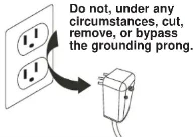
This product is factory equipped with a power supply cord that has a three-pronged grounded plug. It must be plugged into a mating grounding type receptacle in accordance with the National Electrical Code and applicable local codes and ordinances. If the circuit does not have a grounding type receptacle, it is the responsibility and obligation of the customer to exchange the existing receptacle in accordance with the National Electrical Code and applicable local codes and ordinances. The third ground prong should not, under any circumstances, be cut or removed. Never use the cord, the plug or the appliance when they show any sign of damage. Do not use your appliance with an extension cord unless it has been checked and tested by a qualified electrician or electrical supplier.

IMPORTANT - MÉTHODE POUR LA MISE À LA TERRE
Welcome to the Danby family. We are proud of our quality products, and we believe in dependable service, like you will find in this Owner's Use and Care Guide, and like you will receive from our friendly customer service department. Best of all, you will experience these values each and every time you use your Danby appliance. That is important, because your new appliance will be a part of your family for a long time.
For easy reference, we suggest you attach a copy of your sales slip/receipt to this page, along with the following information, located on the manufacturer's nameplate on the right side of the unit above the powercord.
Note the information below; you will need this information to obtain service under warranty. To receive service, you must provide the original receipt.
NOTE: THIS UNIT IS NOT DESIGNED FOR "THROUGH-THE-WALL" INSTALLATION.
Model No:
Serial No:
Date Purchased:
NEED HELP?
Before you call for service, here are a few things you can do to help us serve you better:
Read this Owner's Use and Care Guide:
It contains instructions to help you use and maintain your appliance properly.
If you received a damaged appliance:
Immediately contact the retailer (or builder) that sold you the appliance.
Save time and money:
Check the Troubleshooting section at the end of the guide before calling. This section helps you solve common problems that may occur.
If you do need service, you can relax, knowing help is only a phone call away.

natural_image
Simple black telephone handset icon inside a circle (no text or symbols)1-800-26-Danby (1-800-263-2629)

WARNING
Improper connection of the grounding plug can result in risk of re, electric shock and/or injury to persons associated with the appliance. Check with a qualified service representative if in doubt that the appliance is properly grounded.
FOR YOUR SAFETY: Read these instructions carefully before operating the unit.
ELECTRICAL SPECIFICATIONS
- All wiring must comply with local and national electrical codes and must be installed by a qualified electrician. If you have any questions regarding the following instructions, contact a qualified electrician.
- Check available power supply and resolve any wiring problems BEFORE installing and operating this unit.
- This 115V or 230/208V air conditioner uses 11.5 or less nameplate amps and may be used in any properly wired, general purpose household receptacle. See Table 1 for specifications for individual branch circuit.
- For your safety and protection, this unit is grounded through the powercord plug when plugged into a matching wall outlet. If you are not sure whether your wall outlet is properly grounded, please consult a qualified electrician.
- The wall outlet must match the 3-prong plug on the service cord supplied with the unit. DO NOT use plug adapters. See Table 2 for receptacle and fuse information.
- The rating plate on the unit contains electrical and other technical data. The rating plate is located on the right side of the unit, above the powercord.
| TABLE 1 | |
| Suggested Individual Branch Circuit | |
| Nameplate Amps | *AWG Wire Size |
| 11.5 | 14 |
| AWG- American Wire Guage*Based on copper wire at 105°C (221°F) temperature rating. | |
| TABLE 2 | |
| Recept and Fuse Types | |
| Model DAC150BBCWDB / DAC150BBUWDB | |
| Rated Volts 125 | |
| Amps 15 | |
| Wall Outlet | |
| Fuse Size 15 | |
| Time Delay Fuse Plug Type(or Circuit Breaker) |
text_image
Do not, under any circumstances, cut, remove, or bypass the grounding prong.FOR YOUR SAFETY: Read these instructions carefully before operating the unit.
ENERGY SAVING TIPS
Your appliance is designed to be highly efficient in energy savings. Follow these recommendations for greater efficiency.
- Select a thermostat setting that suits your comfort needs and leave at that chosen setting.
- The air filter is very efficient in removing airborne particles. Keep the air filter clean at all times (usually cleaned every 2 weeks depending on indoor air quality).
- Use drapes, curtains or shades to keep direct sunlight from penetrating and heating the room, but do not allow drapes or curtains to obstruct the air flow around the unit.
- Start your air conditioner before the outdoor air becomes hot, to avoid an initial period of discomfort while the unit is cooling the room.
- When outdoor temperatures are cool enough, use the FAN MODE only, on HIGH, MEDIUM, or LOW setting. This circulates indoor air, providing some cooling comfort, and utilizes less electricity than when operating on a cooling setting.
POWER SUPPLY CORD
The power cord supplied with this air conditioner contains a device that senses damage to the power cord. To test if your power cord is working properly, you must do the following:
- Connect the power supply cord to an electrical outlet.
- The power supply cord has two buttons located on the head of the plug. One button is marked "TEST", and the other is marked "RESET". Press the "TEST" button; you will hear a click as the "RESET" button pops out.
- Press the "RESET" button; you will hear a click as the button engages.
- The power supply cord is now energized and supplying electricity to the air conditioner (on some products this is also indicated by a light on the plug head).
NOTE: The power cord supplied with this air conditioner contains a current leakage detection device designed to reduce the risk of fire. In the event the power supply cord is damaged, it cannot be repaired and must be replaced with a new cord from the product manufacturer.
- Under no circumstances should this device be used to turn the unit on or off.
- The "RESET" button must always be pushed in (engaged) for correct operation.
- The power supply cord must be replaced if it fails to reset when the "TEST" button is pushed in.

text_image
Plug in and press RESET TEST RESETNOTE: Some plugs have buttons on the top.
text_image
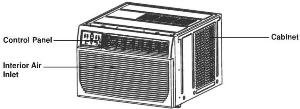
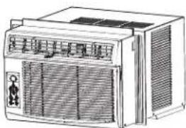
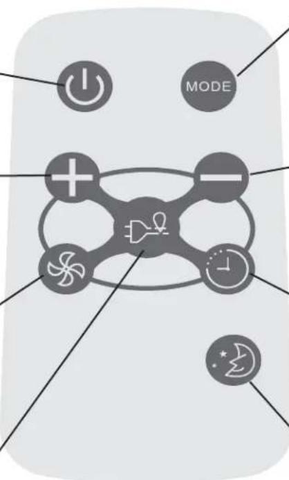
Control Panel Interior Air Inlet CabinetUNIT CONTROL PANEL
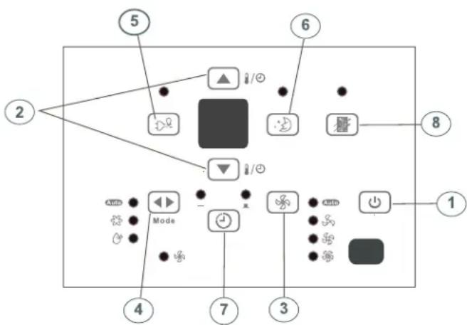
- ON/OFF Button: Press to turn the unit on/off. NOTE: The unit will automatically launch the Energy Saver function when it is in Cool, Dry and Auto modes.
- Temperature UP/DOWN Buttons: To change the temperature setting, press or hold either the UP ( ) or DOWN ( ) button, until the desired temperature is seen on the display. This temperature will be automatically maintained anywhere between 17°C (62°F) and 30°C (86°F). In Cooling mode, the display reads the set temperature, while in Fan mode, the current room temperature is displayed.
- Fan Speed Button: Select from four different fan settings: Auto, Low, Med or High. Each time the button is pressed, the fan speed is shifted.
- Mode Button: Allows you to scroll through and select the desired operating mode: Auto, Cool, Dry and Fan. The selected mode will be denoted by the adjacent indicator light.
Operation in Auto Mode:
- Auto is a pre-set factory program that automatically defines the mode and fan speed, based on the set temperature you have chosen. An example of Auto operation is as follows:
- If you would like to cool down your room, your desired / set temperature will be below the room temperature, and your air conditioner will go into cooling mode. Once the room has reached your desired temperature, the air conditioner will switch to Fan mode, and circulate the cooled air around the room. When the temperature in the room goes up, the unit will switch back to cooling mode, and the Auto cycle will start again.
Operation in Dry Mode:
- Please note that in this mode you cannot set the desired humidity level, it is automatically pre-set. The fan speed in this setting is defaulted to "low". Since the compressor is operating in order to remove moisture from the air, you will experience a degree of cooling as a by-product.
Operation in Fan Only Mode:
- Use this function, when cooling is not desired, such as for room air circulation, or to exhaust stale air. Remember to open the vent during this function, but keep it closed during cooling, for maximum cooling efficiency. In this mode you can choose any fan speed you prefer. In Fan mode, the temperature cannot be set, and the display will read the current room temperature.
- Energy Saver: This is the default setting on this model. The unit will automatically cycle the fan on and off while the compressor is not in use. The fan will continue to run for 3 minutes after the compressor shuts off. The fan then cycles on for 2 minutes at 10 minute intervals, until the room temperature is above the set temperature. At this point, the compressor turns back on and cooling re-starts. When the unit is in Energy Saver mode, the indicator light above the Energy Saver button will be illuminated. You can take the unit out of Energy Saver mode by pressing the Energy Saver button - the indicator light about the button will turn off. If you choose the non-Energy Saver option, the fan will run continuously when the compressor is not in use.
UNIT CONTROL PANEL
- Sleep Button: Press the Sleep button to initiate the Sleep mode. In this mode, the selected temperature will increase (when in cooling mode) by 1°C (2°F) one half-hour after Sleep mode has been selected. The temperature will then increase by another 1°C (2°F) after an additional half-hour. This new temperature will be maintained for 6 hours before returning to the originally selected temperature. This ends the Sleep mode and the unit will continue to operate as originally programmed. The Sleep mode program can be cancelled at any time during operation by pressing the Sleep button again.
- Timer (Auto Start / Stop Feature) Button: Pressing the Timer button will illuminate the indicator beside the word "On". This indicates that the Auto Start program has been initiated. Press or hold the Up (▲) or Down (▼) buttons to change the Auto time by 0.5 hour increments, up to 10 hours, then at 1 hour increments up to 24 hours. The control will count down the time remaining until the start of the program. The selected time will register in 5 seconds and the system will automatically revert back to displaying the previous temperature setting. Turning the unit ON or OFF at any time will cancel the Auto Start/Stop function.
- Check Filter Button: This feature is a reminder to clean the air filter for more efficient operation. The LED (light) illuminates after 250 hours of operation. To reset after cleaning the filter, press the check filter button and the light will go off.
ADDITIONAL FEATURES:
- The Cool circuit has an automatic 3 minute time delayed start if the unit is turned off and on quickly. This prevents overheating of the compressor and possible circuit breaker tripping. The fan will continue to run during this time.
- The control will maintain any set temperature within 2^ , between 15^ - 32^ ( 60^ - 90^ ).
- The control is capable of displaying temperature in Celsius (°C) or Fahrenheit (°F). To convert from one to the other, press and hold the UP and DOWN Temp./Timer buttons at the same time for 3 seconds.
flowchart
graph TD
    2 --> 5
    5 --> 6
    6 --> 8
    8 --> 1
    4 --> 7
    7 --> 3
    3 --> 1
    5 --> Mode
    Mode --> Control
    Control --> 6
    Control --> 8
    6 --> Control
    8 --> Control
    style 5 fill:#000,stroke:#000,color:#fff
    style 6 fill:#000,stroke:#000,color:#fff
    style 8 fill:#000,stroke:#000,color:#fff
    style 1 fill:#000,stroke:#000,color:#fff
    style 4 fill:#000,stroke:#000,color:#fff
    style 7 fill:#000,stroke:#000,color:#fff
    style 3 fill:#000,stroke:#000,color:#fff
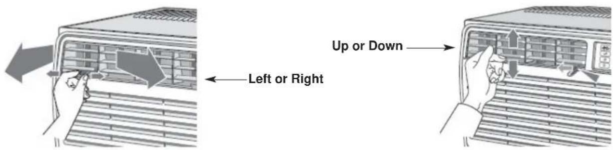
ADJUSTING AIR FLOW
The 4-way air directional louvers allow you to direct the air flow up or down and left or right throughout the room as needed.
RECOMMENDATION: When cooling, adjust blades to face upward. If you orient the air flow blades downward and the unit operates in cool mode for long periods of time, dew may form and drip from the surface of the blades.
text_image
Up or Down Left or Right
OPERATING INSTRUCTIONS
USING THE REMOTE CONTROL
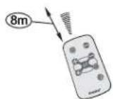
Location of the remote controller
natural_image
Line drawing of a portable air conditioner unit with ventilation grilles and control panel (no text or symbols)- Use the remote controller within a distance of 8 meters from the appliance, pointing it towards the receiver. Reception is confirmed by a beep.
CAUTION
- The air conditioner will not operate if curtains, doors or other materials block the signals from the remote controller to the indoor unit.
- Prevent any liquid from falling into the remote controller. Do not expose the remote controller to direct sunlight or heat.
- If the infrared signal receiver on the indoor unit is exposed to direct sunlight, the air conditioner may not function properly. Use curtains to prevent the sunlight from falling on the receiver.
- If other electrical appliances react to the remote controller, either move these appliances or call the service depot.
REMOTE CONTROLLER SPECIFICATIONS
| Model R15B | |
| Rated Voltage 3.0V | |
| Battery Type Button cell: CR2025 | |
| Battery Quantity 1pcs | |
| Lowest Voltage of CPU Emitting Signal 2.0V | |
| Signal Receiving Range 8m | |
| Environment -8°C to 60°C (18°F to 140°F) |
ON/OFF BUTTON
Operation starts when this button is pressed and stops when the button is pressed again. NOTE: The unit will automatically launch the Energy Saver function when it is in Cool, Dry, and Auto modes (Only Auto-Cool and Auto-Fan modes.)
TEMP UP BUTTON
Push this button to increase the temperature setting in 1°C (1°F) increments to 30°C (86°F).
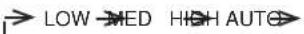
FAN BUTTON
Used to select the fan speed in four steps:
ENERGY SAVER BUTTON
Press this button to activate the energy saving mode. Press it again to stop the function. This function is available in COOL, DRY, and AUTO modes (only Auto-cool and Auto-fan modes).
flowchart
graph TD
    A["Power"] --> B["+"]
    C["Mode"] --> D["-"]
    E["Feedback"] --> F["Drain Icon"]
    G["Control"] --> H["Clock Icon"]
    I["Feedback"] --> J["Star Icon"]
Each time you press this button, a mode is selected in a sequence that consists of AUTO, COOL, DRY, FAN, and back to AUTO.
TEMP DOWN BUTTON
Push this button to decrease the indoor temperature setting in 1°C (1°F) increments to 17°C (62°F).
TIMER BUTTON
Push this button to activate the "Auto Start" or "Auto Stop" program from 0-24 hours (0.5/1 hour increments).
SLEEP BUTTON
Press this button to activate the SLEEP mode. This function is available in COOL, and AUTO modes only, and maintains the most comfortable temperature for you.
USING THE REMOTE CONTROLLER BUTTONS
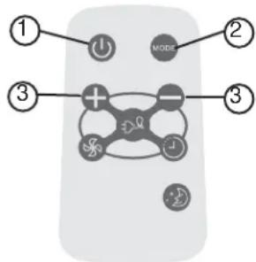
AUTO OPERATION
text_image
① ② MODE ③ + - ③Ensure the unit is plugged in and power is available.
- Press the ON/OFF button to start the air conditioner.
- Press the mode button and select AUTO.
- Press the TEMP + / - button to set the desired temperature. The temperature can be set within a range of 17°C (62°F) to 30°C (86°F) in 1°C (1°F) increments.
NOTE:
- In the auto mode, the air conditioner can logically choose the mode of Cool, Fan, Dehumidifying by sensing the difference between the actual ambient room temperature and the set temperature on the remote controller.
- In Auto mode, you cannot change the fan speed. It has already been automatically controlled.
- If the Auto mode is not comfortable for you, the desired mode can be selected manually.
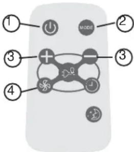
text_image
① ② MODE ③ ③ ④Ensure the unit is plugged in and power is available.
- Press the ON/OFF button to start the air conditioner.
- Press the MODE button to select Cool mode.
- Press the TEMP +/- button to set the desired temperature. The temperature can be set within a range of 17^ C ( 62^ F) to 30^ C ( 86^ F) in 1^ C ( 1^ F) increments.
- Press the FAN button to select the fan speed in four-steps, LOW, MED, HIGH or AUTO.
NOTE:
In the FAN mode, the setting temperature is not displayed in the remote controller and you are not able to control the room temperature either. In this case, only step 1, 2 and 4 may be performed.
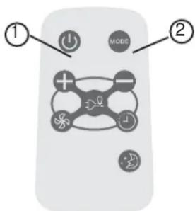
text_image
① ② MODEEnsure the unit is plugged in and power is available.
- Press the ON/OFF button to start the air conditioner.
- Press the MODE button to select Dehumidifying mode.
NOTE:
In the Dehumidifying mode, you cannot change the fan speed. It has already been automatically controlled.
USING THE REMOTE CONTROLLER BUTTONS
SLEEP OPERATION
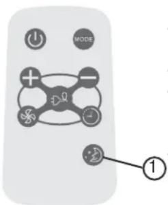
text_image
MODE ①- In this mode, the selected temperature will increase (when in cooling mode) by 1^ (2^) one half-hour after sleep mode has been selected.
- The temperature will increase by another 1^ (2°F) after an additional half-hour.
- This new temperature will be maintained for 6 hours before returning to the originally selected temperature. This ends the Sleep mode and the unit will continue to operate as originally programmed.
- The Sleep mode program can be cancelled at any time during operation by pressing the Sleep button again.
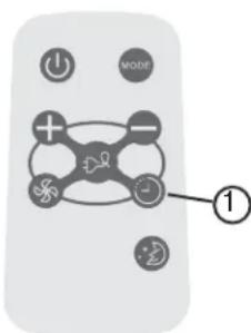
text_image
Diagram of a remote control with labeled buttons and icons, highlighting one button as '1'Pressing the TIMER button can set the Auto-start and Auto-stop time of the unit.
NOTE:
- To set Auto-start time, the unit must be in the OFF position.
- To set Auto-stop time, the unit must be in the ON position.
To set the Auto-start time
- Push the TIMER button when the unit is off; only the Auto-start feature can be set.
-
Keep pressing the TIMER button. Each time pressed, will increase the selected time by 0.5 hour increments. When the selected time has added up to 10 hours, each time pressed will increase the selected time by 1 hour increments, up to 24 hours.
-
The time can be set in the range of 0-24 hours.
-
After the desired time has been selected, wait for about 10 seconds, until the setting temperature reappears in the display window of the air conditioner. This indicates that the program has been set.
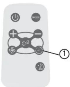
text_image
Diagram of a remote control with labeled buttons and icons, highlighting one button as '1'To set the Auto-stop time
- Push the TIMER button when the unit is operational; only the Auto-stop feature can be set.
- Keep pressing the TIMER button. Each time pressed will increase the selected time by 1 hour increments, up to 24 hours.
- The time can be set in a range of 0-24 hours.
- After the desired time has been selected, wait for about 10 seconds, until the setting temperature reappears in the display window of the air conditioner. This indicates that the program has been set.
NOTE:
To cancel the TIMER setting, push the TIMER button until "0 hours" is displayed on the LCD window of the air conditioner.
USING THE REMOTE CONTROLLER BUTTONS
This function is available in Cool, Dry, and Auto modes (only Auto-Cool and Auto-Fan modes). The fan will continue to run for 3 minutes after the compressor has shut off. The fan then cycles on for 2 minutes at 10 minute intervals, until the room temperature is above the set temperature. At this point, the compressor turns back on and cooling starts.
- Protect the remote control from high temperatures, and keep it away from radiation exposure.
- Keep the control panel receiver out of direct sunlight.
- If the remote control will not be used for extended periods of time (vacations etc.), the battery should be removed.
- This Class B digital apparatus complies with the Canadian ICES-003 standard.
- The remote operates within a range of 8 meters (26 ft.) from the receiver located inside the main unit. Any obstruction between the receiver and remote may cause signal interference, limiting the ability to program the main unit.
Note: This equipment has been tested and found to comply with the limits for a Class B digital device, pursuant to Part 15 of the FCC Rules. These limits are designed to provide reasonable protection against harmful interference in a residential installation. This equipment generates, uses and can radiate radio frequency energy and, if not installed and used in accordance with the instructions, may cause harmful interference to radio communications. However, there is no guarantee that interference will not occur in a particular installation. If this equipment does cause harmful interference to radio or television reception, which can be determined by turning the equipment off and on, the user is encouraged to try to correct the interference by one or more of the following measures:
- Reorient or relocate the receiving antenna.
- Increase the separation between the equipment and receiver.
- Connect the equipment into an outlet on a circuit different from that to which the receiver is connected.
- Consult the dealer or an experienced radio/TV technician for help. Changes or modifications not approved by the party responsible for FCC compliance could void the user's authority to operate the equipment.
This appliance complies with Part 15 of the FCC Rules. Operation is subject to the following two conditions:
- This device may not cause harmful interference.
- This device must accept any interference received, including interference that may cause undesired operation.
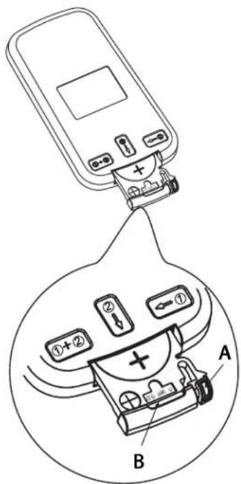
text_image
Diagram showing a device with labeled components and a magnified view of its internal components, labeled A and B.The remote controller is powered by one button cell housed in the rear part and protected by a cover. Remove the button cell according to the arrow marked at the back of the remote controller.

- Slightly press "A" position according to the number 1 arrow direction by your forefinger.

- Press "B" position and pull it according to the number 2 arrow direction by your thumb.

- The above step 1 and 2 should be done simultaneously to slide the button cell out.

INSTALLATION INSTRUCTIONS

ELECTRIC SHOCK HAZARD
To avoid the possibility of personal injury, disconnect power to the unit before installing or servicing.
NOTE: Your Room Air Conditioner is designed for easy installation in a single or double-hung window. This unit is NOT designed for vertical (slider type) windows and/or through-the-wall applications.
TOOLS NEEDED FOR INSTALLATION:
- Screwdrivers: Phillips and flat head.
• Power Drill: 1/8in. (3.2mm) diameter drill bit - Pencil
- Measuring Tape
- Scissors
- Carpenter's Level
BEFORE INSTALLING
- Check window opening size against dimensions of your unit.
- Check condition of window; all wood parts of the window must be in good shape and able to firmly hold the needed screws. If not, make repairs before installing unit.
- Check for anything that could block airflow; check area outside window for things such as shrubs, trees, or awnings. Inside, be sure furniture, drapes or blinds will not stop proper air flow.
- Carefully unpack air conditioner. Remove all packing material, and check for all included installation hardware.
| Model type: DAC150BBCWDBDAC150BBUWDB | |
| Unit height: 17.91 | |
| Unit width: 23.62 | |
| Min. window opening: 18 1/2" | |
| Min. window width: 27 3/4" | |
| Max. window width: 40 1/2" | |
| Fig. 1 INSTALLATION HARDWARE | ||
| 7/16" locking screw & flat washer for window panels | 2 each | |
| 1/2in.(13mm) long Hex-head screw | 7 | |
| Safety Lock | 1 | |
| 1/2in.(12.7mm) long screw and locknut | 4 each | |
| 3/4" long flat head bolt and locknut | 2 each | |
| Sill Angle Bracket | 2 | |
| 5/16in. long Hex-head locking screw for top angle side retainer. | 10 | |
| 13/16in. (20mm) screw | 2 | |
| Frame lock | 2 | |
| Foam insert | 2 | |
| Window sash seal foam | 1 | |
| Weather-Stripping | 5 | |
| Foam Insert | 2 | |
LOCATION
- This room air conditioner is designed to fit easily into a single or double hung window. However, since window designs vary, it may be necessary to make some modifications for safe, proper installation.
- Make sure window and frame are structurally sound and free from dry and rotted wood.
- For maximum efficiency, install the air conditioner on a side of the house or building which favours more shade than sunlight. If the unit is in direct sunlight, it is advisable to provide an awning over the unit.
- Provide sufficient clearance around the cabinet to allow for ample air circulation through the unit (See Fig. 2). The rear of the unit should be outdoors. It should not be in a garage, or inside a building. Keep unit as far away as possible from obstacles/obstructions and at least 30 in. (76 cm) above the floor or ground. Curtains and other objects within the room should be prevented from blocking the air flow.
- Be certain that the proper electrical outlet is within reach of the installation. Use only a single outlet circuit rated at 15 amps. All wiring should be in accordance with local and national electrical codes.
- DO NOT install unit where leakage of combustible gas is suspected. Your air conditioner may fail to operate in air containing oils (including machine oils), sulfide gas, near hot springs, etc.
NOTE: Your unit is designed to evaporate condensation under normal conditions. However, under extreme humidity conditions, excess condensation may cause basepan to overflow to the outside. The unit should be installed where condensation run-off cannot drip on pedestrians or neighbouring properties.
NOTE: It is normal for your unit to drip a small amount of water, especially on excessively humid days.
NOTE: Save the shipping carton and packing materials for future storage or transportation. From the carton, remove the plastic bag containing the installation hardware kit necessary for the installation of your air conditioner. Please check the contents of the hardware kit against the corresponding model check list, prior to installation.
NOTE: Your Room Air Conditioner is designed for easy installation in a single or double-hung window. This unit is NOT designed for vertical (slider type) windows and/or through-the-wall applications.
CAUTION
Because the compressor is located on the controls side of the unit (left side), this side will be heavier and more awkward to manipulate. Inadequate support on the control side of the unit can cause injury and damage to the appliance and other property. Therefore, it is recommended that you have someone assist you during the installation of this unit.
Fig. 2
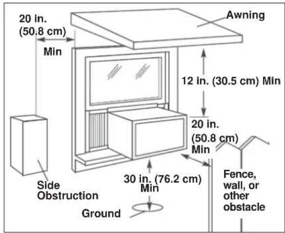
text_image
20 in. (50.8 cm) Min Side Obstruction Ground 30 in. (76.2 cm) Min 12 in. (30.5 cm) Min Awning 20 in. (50.8 cm) Min Fence, wall, or other obstacleWINDOW MOUNTING
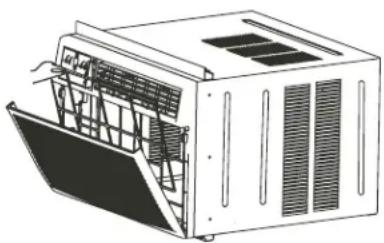
1 Remove Chassis:
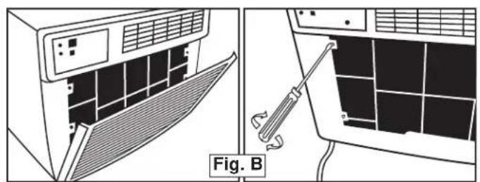
- Pull down front panel and remove fi Iter (See Fig. A).
- Lift front panel upwards and place to one side.
- Locate the four (4) front screws and remove (Fig. B). These screws will be needed to re-install the front later.
- Pry away the front panel from the cabinet sides as shown in Fig. C.
natural_image
Diagram showing airflow control between an air conditioner unit and a solar panel array, with no visible text or symbols.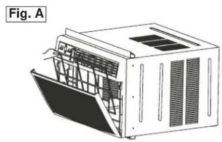
natural_image
Technical line drawing of a modular air conditioner unit (no text or symbols)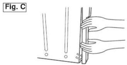
natural_image
Illustration of hands holding a tool or bracket with a ruler, labeled 'Fig. C' (no text or symbols on the diagram itself)- Gently lift front off unit and place to one side (See fig. D)
- Remove shipping screw from top of unit and also on the side by the base if installed.
- Hold the cabinet while pulling on the base handle, and carefully remove the chassis from the cabinet.
- Add two foam inserts to holes in top of cabinet where shipping screws were removed from (See fig. E).
- Your unit may come with internal packaging. This packaging must be removed prior to installing the air conditioner back into the cabinet.

natural_image
Illustration of hands installing or adjusting a wall-mounted air conditioner unit (no text or symbols visible)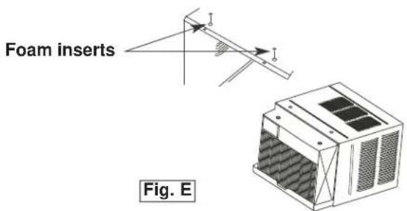
text_image
Foam inserts Fig. E
INSTALLATION INSTRUCTIONS
2 Install Top Angle and Side Bracket:
- Attach foam gasket to top angle above holes as shown in Fig. F.
- Install top angle and side retainers to cabinet as shown in Fig. F.
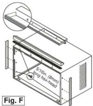
text_image
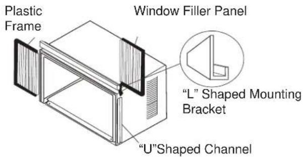
5/16in. (9mm) long hex-head Fig. F3 Assemble Window Filler Panels (see Fig. G):
- Place cabinet on floor, a bench, or table.
- Slide the window fi ller panel frame into the top (L shaped) and bottom (U shaped) channels. The shutters are identifi ed (on the frame) as left and right.
- Insert washer head locking screws (2) into holes in top leg of fler panel frame. Do not totally tighten. Allow left to slide freely. Screws will be tightened later.
text_image
Plastic Frame Window Filler Panel "L" Shaped Mounting Bracket "U"Shaped Channel4 Install Top Angle and Side Bracket:
- Open window and mark center of window sill.
- Place cabinet in window with lower "U" channel of cabinet fi rmly seated over window sill. Bring window down temporarily behind top "L" bracket to hold cabinet in place.
- Shift cabinet left or right as needed to line up center of cabinet on centre line marked on window sill.
- Fasten cabinet to window sill with 2 screws (you may want to pre-drill holes).
- Add bottom rail seal over screws to window sill. See Fig. H.
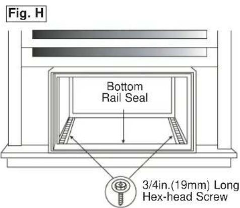
text_image
Fig. H Bottom Rail Seal 3/4in.(19mm) Long Hex-head Screw
INSTALLATION INSTRUCTIONS
5 Install Support Bracket:
- Hold each support bracket flush against outside of sill, and tighten to bottom of cabinet as shown. in Fig. J1. Mark brackets at top level of sill, and remove.
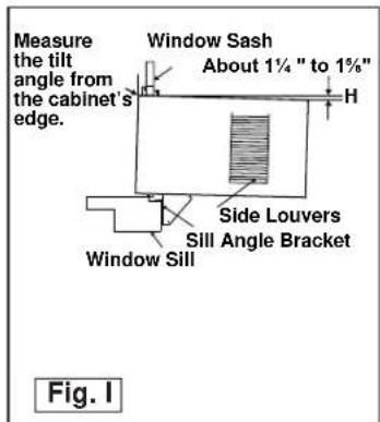
- Assemble sill anchor bracket to outside support legs at the market position, as seen in Fig. J 2. Hand tighten, but allow for any changes later. NOTE: Check that air conditioner is tilted downwards to the outside, about 3^ to 4^ , as shown in Fig. I. After installation, condensed water should not drain from the overflow drain hole during normal use. If you notice water leaking out, check the angle of tilt, and make any necessary adjustments. However, on a very humid day, water leakage can occur- this is normal. Measure the tilt angle from the cabinet's edge . The distance H should be approximately 1 1/4" to 1 5/8".
- Install support brackets (with sill anchor brackets attached) to correct hole in bottom of cabinet as shown in Fig. K.
- Tighten all 6 bolts securely.
text_image
Measure the tilt angle from the cabinet's edge. Window Sash About 1¼ " to 1%" H Side Louvers Sill Angle Bracket Window Sill Fig. I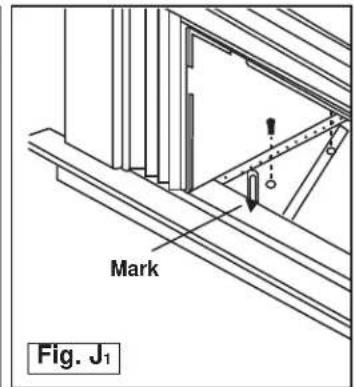
text_image
Mark Fig. J₁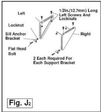
text_image
Left Locknut Sill Anchor Bracket Flat Head Bolt 1:2in.(12.7mm) Long Left Screws And Locknuts Right 2 Each Required For Each Support Bracket Fig. J₂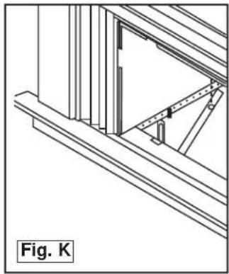
natural_image
Architectural line drawing of a window frame structure with diagonal braces and a triangular support (no text or symbols)6 Extend Window Filler Panels
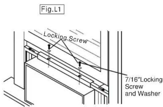
- Carefully raise the window to expose the filler panel locking screws. Loosen the screws do the filler panels slide easily.
- Extend panels to fill the widow completely. Using two 7/16 in (12mm) locking screws and a flat washer to tighten the locking screws on top (Fig. L1).
- Close the window behind the top angle.
- Attach the top angle to the window frame using a 3/32 drill bit to drill one hole through the hole in the middle of the top angle into the window frame, and drive one 12 HEX-HEAD locking screw through the hole in the middle of the top angle into the window frame, see Fig. L2.
- Extend the window filler panels out against the window frame.
- Use a 1/8" drill bit to drill a starter hole through the hole in the top leg of each window filler panel and into the window sash (Fig. L3). Connect with one 1/2" long hex head screw.
- Attach the frame lock to the window sill using one 13/16" (20mm) screw on each side as shown in Fig. L3.
text_image
Fig.L1 Locking Screw 7/16"Locking Screw and Washer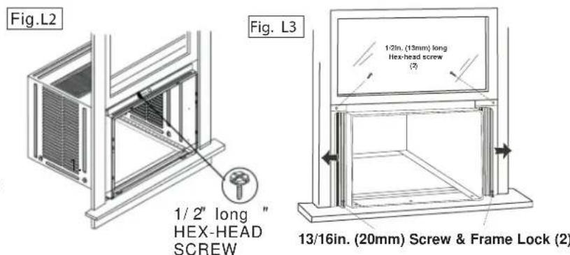
text_image
Fig.L2 1/ 2" long " HEX-HEAD SCREW Fig. L3 1/2in. (13mm) long Hex-head screw (2) 13/16in. (20mm) Screw & Frame Lock (2)
INSTALLATION INSTRUCTIONS
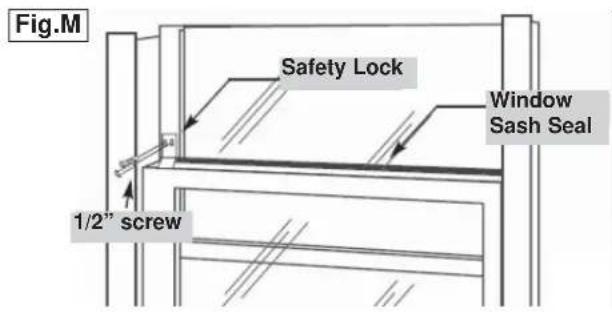
7 Install Window Lock and Sash Seal
- Trim sash seal to fit window width. Insert into space between upper and lower sashes (Fig. M).
- Attach right angle safety lock as shown in Fig. M.
Install Chassis into Cabinet and Install:
- Lift chassis and carefully slide into cabinet, leaving 6 inches protruding.
- DO NOT push on controls or coils.
- Be sure the chassis is firmly seated towards rear of cabinet.
- Installation of front is the reverse of removal, outlined in section 1 ("Remove Chassis")
text_image
Fig.M Safety Lock Window Sash Seal 1/2" screwInstalling the Energy Efficient Foam Insert
- After the unit is installed in the window, measure the width of the side curtain.
- If necessary, cut the foam insert down to the width of the side curtain.
- Slide the foam insert into the side curtain.
- Repeat for the other side. (See below)
NOTE: Apply the supplied weather-stripping where needed (cracks and spaces between the foam insert, window kit and window frame).
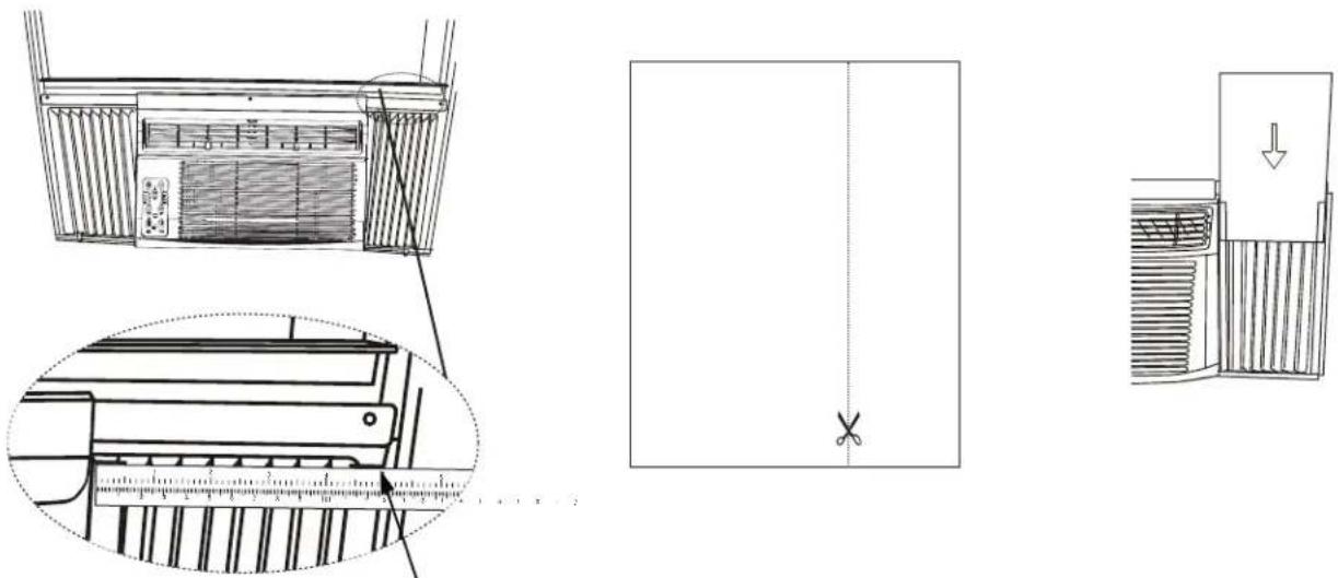
Step 1 Step 3Step 2

CARE AND MAINTENANCE
CAUTION
Before cleaning or servicing this unit, disconnect from any electrical supply outlets to prevent possible shock or re hazard.
- DO NOT use gasoline, benzene, thinner, or any other chemicals to clean this unit, as these substances may cause damage to the fi nish and deformation of plastic parts.
- Never use harsh cleaners, wax or polish on the cabinet front.
CLEANING THE AIR FILTER
The air filter should be checked at least once a month to see if cleaning is necessary. Trapped particles in the filter can build up and cause accumulation of frost on the cooling coils.
- Push the vent handle to the vent closed position.
- Open the front panel.
- Grasp the filter, pull up and out.
- Wash the filter using liquid dishwashing detergent and warm water. Rinse filter thoroughly.
- Gently shake excess water from the filter. Be sure the filter is thoroughly dry before replacing.
- You may vacuum the fi Iter to clean.
Note: Never use hot water over 40^ C ( 104^ F) to clean the air filter.
CAUTION
Never operate this unit without the air filter in place, as this may result in damage to the unit.
natural_image
Technical line drawing of a modular air conditioner unit with cooling fins and ventilation grilles (no text or symbols)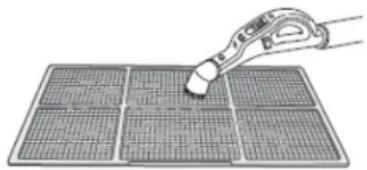
natural_image
Illustration of a hand using a tool to cut or mark a grid pattern on a solar panel (no text or symbols)CLEANING THE CABINET
- Be sure to unplug the air conditioner to prevent shock or fire hazard. The cabinet and front may be dusted with an oil-free cloth or washed with a soft cloth dampened in a solution of warm water and mild liquid dishwashing detergent. Rinse thoroughly and wipe dry.
- Be sure to wring excess water from the cloth before wiping around the controls. Excess water in or around the controls may cause damage to the air conditioner.
WINTER STORAGE
If you plan to store the air conditioner during the winter, remove it carefully from the window according to the installation instructions. Cover it with plastic or return it to the original carton. Always store the unit in the upright position.
DISPOSAL
Check for local regulatory compliance regarding the approved and safe disposal of this appliance.
Occasionally a problem may arise that is minor in nature, and a service call may not be necessary. Use this troubleshooting guide for a possible solution. If the unit continues to operate improperly, call an authorized service depot or Danby's Toll Free Number 1-800-263-2629 for assistance.
PROBLEM POSSIBLE CAUSE SOLUTION
| Unit does not work • Power is out | The plug is not plugged in properlyPlug current device trippedControl is off | Wait for power to returnPlug in properlyPress the reset button after resolving problemTurn control ON and set to desired setting |
| Air from unit does not feel cold enough | Room temp. below 17°C (62°F)Temp. sensing element touching cold coil (behind air fi liter)Temp. set too highCompressor shut off by changing modes | Will not cool until room temp. rises above 17°C (62°F)Straighten tube away from coilReset to a lower temp.Wait approx. 3 minutes and listen for compressor to restart when in cool mode |
| Air conditioner cooling but room is too warm- ice forming on cooling coil behind decorative front | Outdoor temp. below 17°C (62°F)Air fi liter may be dirtyThermostat too cold for night-time cooling | To defrost coil, set to FAN ONLYClean fi liter as per instructionsSet temp. to a higher setting |
| Air conditioner cooling but room is too warm- NO ice forming on cooling coil behind decorative front | Dirty air fi liter - air restrictedTemp. is set too highAir directional louvers positioned improperlyFront of unit blocked (i.e. by drapes), restricting air distributionDoors, windows, registers etc.open, cold air escapingUnit recently turned on in hot room | Clean air fi literSet to lower temp.Position louvers for better air distributionClear blockage in front of unitClose doors, windows, registersallow additional time to remove “stored heat” from room |
| Air conditioner turns on and off rapidly | Dirty air fi liter - air restrictedOutside temp. extremely hot | Clean air fi literSet fan speed to higher setting to bring air past cooling coils more frequently |
| Noise when unit is cooling • Air movement soundWindow vibration | This is normal. If too loud, set to slower fan settingPoor installation-refer to installation instructions or check with installer | |
| Water dripping INSIDE when unit is cooling | Improper installation • Tilt air conditioner slightly to the outside to allow water drainage | |
| Water dripping OUTSIDE when unit is cooling | Unit removing large quantity of moisture from humid room | This is normal during excessively humid days |
| Remote sensing deactivating prematurely | Remote control not located within rangeRemote control signal obstructed | Place remote control withing 8 meters (20 Ft.) and 180° radius of front of the unitRemove obstruction |
| Room too cold • Set temperature too low • Increase set temperature | ||
LIMITED IN-HOME APPLIANCE WARRANTY
This quality product is warranted to be free from manufacturer's defects in material and workmanship, provided that the unit is used under the normal operating conditions intended by the manufacturer.
This warranty is available only to the person to whom the unit was originally sold by Danby Products Limited (Canada) or Danby Products Inc. (U.S.A.) (hereafter "Danby") or by an authorized distributor of Danby, and is non-transferable.
TERMS OF WARRANTY
Plastic parts, are warranted for thirty (30) days only from purchase date, with no extensions provided.
| First year | During the first twelve (12) months, any functional parts of this product found to be defective, will be repaired or replaced, at warrantor's option, at no charge to the ORIGINAL purchaser. |
| To obtain service | Danby reserves the right to limit the boundaries of “In Home Service” to the proximity of an Authorized Service Depot. Any appliance requiring service outside the limited boundaries of “In Home Service”, it will be the consumer's responsibility to transport the appliance (at their own expense) to the original retailer (point of purchase) or a service depot for repair. See “Boundaries of In Home Service” below. Contact your dealer from whom your unit was purchased, or contact your nearest authorized Danby service depot, where service must be performed by a qualified service technician. If service is performed on the units by anyone other than an authorized service depot, or the unit is used for commercial application, all obligations of Danby under this warranty shall be void. |
| Boundaries of in-home service | If the appliance is installed in a location that is 100 kilometres (62 miles) or more from the nearest service centre your unit must be delivered to the nearest authorized Danby Service Depot, as service must only be performed by a technician qualified and certified for warranty service by Danby. Transportation charges to and from the service location are not protected by this warranty and are the responsibility of the purchaser. |
Nothing within this warranty shall imply that Danby will be responsible or liable for any spoilage or damage to food or other contents of this appliance, whether due to any defect of the appliance, or its use, whether proper or improper.
EXCLUSIONS
Save as herein provided, by Danby, there are no other warranties, conditions, representations or guarantees, express or implied, made or intended by Danby or its authorized distributors and all other warranties, conditions, representations or guarantees, including any warranties, conditions, representations or guarantees under any Sale of Goods Act or like legislation or statute is hereby expressly excluded. Save as herein provided, Danby shall not be responsible for any damages to persons or property, including the unit itself, howsoever caused or any consequential damages arising from the malfunction of the unit and by the purchase of the unit, the purchaser does hereby agree to indemnify and hold harmless Danby from any claim for damages to persons or property caused by the unit.
GENERAL PROVISIONS
No warranty or insurance herein contained or set out shall apply when damage or repair is caused by any of the following:
1) Power failure.
2) Damage in transit or when moving the appliance.
3) Improper power supply such as low voltage, defective house wiring or inadequate fuses.
4) Accident, alteration, abuse or misuse of the appliance such as inadequate air circulation in the room or abnormal operating conditions (extremely high or low room temperature).
5) Use for commercial or industrial purposes (i.e., If the appliance is not installed in a domestic residence).
6) Fire, water damage, theft, war, riot, hostility, acts of God such as hurricanes, floods etc.
7) Service calls resulting in customer education.
8) Improper Installation (i.e., building-in of a free standing appliance or using an appliance outdoors that is not approved for outdoor application). Proof of purchase date will be required for warranty claims; so, please retain bills of sale. In the event warranty service is required, present this document to our AUTHORIZED SERVICE DEPOT.
Warranty Service
In-home
Danby Products Limited
PO Box 1778, Guelph, Ontario, Canada N1H 6Z9
Telephone: (519) 837-0920 FAX: (519) 837-0449
1-800-263-2629
07/14
Danby Products Inc.
PO Box 669, Findlay, Ohio, U.S.A. 45840
Telephone: (419) 425-8627 FAX: (419) 425-8629
BIENVENUE
natural_image
Line drawing of a portable air conditioner unit with ventilation grilles and control panel (no text or symbols)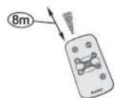
text_image
Diagram of a remote control with labeled buttons and icons, highlighting one button as point 1text_image
Diagram showing a device with labeled components A and B, including battery, switch, and power plug connections.natural_image
Illustration of hands installing or adjusting a wall-mounted air conditioner unit (no text or symbols visible)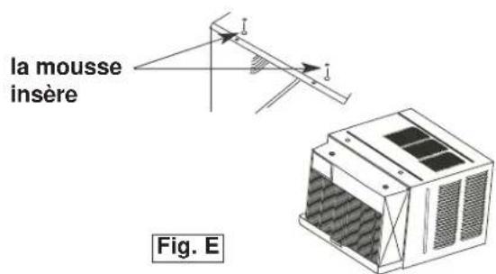
text_image
la mousse insère Fig. E
CONSIGNES D'INSTALLATION
2
text_image
5/16in (8mm) hexagonale Fig. F3
natural_image
Architectural line drawing of a window frame structure with diagonal braces and a door (no text or symbols)6
natural_image
Technical line drawing of a mechanical device with internal components and a magnified inset showing measurement scale (no text or symbols)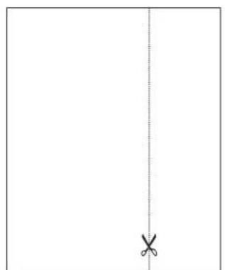
natural_image
Simple line drawing of a vertical line with a cross mark at the bottom (no text or symbols)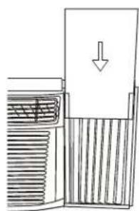
natural_image
Diagram of a mechanical device with internal components and a downward arrow indicating motion (no text or symbols)natural_image
Technical line drawing of a modular air conditioner unit with ventilation grilles and cooling fins (no text or symbols)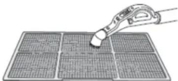
natural_image
Illustration of a pipette interacting with a grid-patterned solar panel (no text or symbols)MISE EN GARDE
Danby Products Limited
PO Box 1778, Guelph, Ontario, Canada N1H 6Z9
All repair parts are available for purchase or special order when you visit your nearest service depot. To request service and/or the location of the service depot nearest you, call the TOLL FREE number.
When requesting service or ordering parts, always provide the following information:
- Product Type
- Model Number
- Part Number
- Part Description
natural_image
Simple black-and-white icon of a telephone handset inside a circle (no text or symbols)1-800-26- Danby
(1-800-263-2629)
MODEL • MODÈLE
DAC150BBCWDB / DAC150BBUWDB