DPA050B7BDB-RF - Air-conditioner DANBY - Free user manual and instructions
Find the device manual for free DPA050B7BDB-RF DANBY in PDF.

User questions about DPA050B7BDB-RF DANBY
0 question about this device. Answer the ones you know or ask your own.
Ask a new question about this device
Download the instructions for your Air-conditioner in PDF format for free! Find your manual DPA050B7BDB-RF - DANBY and take your electronic device back in hand. On this page are published all the documents necessary for the use of your device. DPA050B7BDB-RF by DANBY.
USER MANUAL DPA050B7BDB-RF DANBY
text_image
CERTIFIED Danby CERTIFIEDOWNER'S MANUAL MANUEL DU PROPRIÉTAIRE MANUAL DEL PROPIETARIO
PORTABLE AIR CONDITIONER Owner's Manual....1 - 20
Danby Products Limited, Guelph, Ontario, Canada N1H 6Z9
Danby Products Inc. Findlay, Ohio, U.S.A. 45840
www.Danby.com

*Trademark of Danby Products
*Marque de commerce de Danby Products
*Marca registrada de Danby Products
2022.11.01
Printed in Canada or USA
Welcome to the Danby family.
We are proud of our quality products and we believe in dependable service. We suggest that you read this owner's manual before plugging in your new appliance as it contains important operation information, safety information, troubleshooting, and maintenance tips to ensure the reliability and longevity of your appliance.
You are entitled to the warranty coverage as described in the owner's manual provided with your new appliance.
Please write down your appliance information below. You must keep the original proof of purchase receipt to validate and receive warranty services.
Model Number:
Serial Number:
Date of Purchase:
Need Help?
- Read your Owner's Manual for installation help, troubleshooting, and maintenance assistance.
- Visit www.Danby.com to access self-service tools, FAQs and much more by searching your model number in the search bar.
- For the Quickest Customer Service, please fill out the web form at www.danby.com/support. Your submission will go directly to an expert on your particular appliance. Our average response times are between 20 minutes and 2 hours, during EST business hours.
- Call 1-800-263-2629 - please note that during peak hours, hold times can exceed one hour.
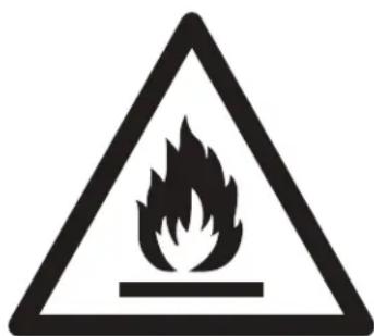
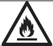 | WARNING Shows that the appliance uses a fl ammable refrigerant. If the refrigerant leaks and is exposed to an external ignition source, there is a risk of fi re. |
 | CAUTION Shows that the operation manual should be read carefully. |
 | CAUTION Shows that service personnel should be handling this equipment with reference to the installation manual. |
 | CAUTION Shows that the information is available such as the operating manual or the installation manual. |
text_image
Warning sign depicting a flame symbol in a triangular shape, indicating hazard or caution.CAUTION: RISK OF FIRE
Flammable refrigerant used. When maintaining or disposing of the air conditioner, the refrigerant must not be allowed to vent into the open air.
SAFETY PRECAUTIONS
WARNING
- Installation must be performed according to the installation instructions. Improper installation can cause water leakage, electrical shock or fire.
- Use only the included accessories and parts and specified tools for the installation. Using non-standard parts can cause water leakage, electrical shock, fire, injury or property damage.
- Make sure that the outlet is grounded and has the appropriate voltage. The power cord is equipped with a three-prong grounding plug to protect against shock. Voltage information can be found on the nameplate of the unit.
- The unit must be used in a properly grounded wall receptacle. If the wall receptacle is not adequately grounded or protected by a time delay fuse or circuit breaker (the fuse of circuit breaker needed is determined by the maximum current of the unit. The maximum current is indicated on the nameplate located on the unit), have a qualified electrician install the proper receptacle.
- Install the unit on a flat, sturdy surface. Failure to do so could result in damage or excessive noise and vibration.
- The unit must be kept free from obstruction to ensure proper function and to mitigate safety hazards.
- Do not modify the length of the power cord or use an extension cord to power the unit.
- Do not share a single outlet with other electrical appliances. Improper power supply can cause fire or electrical shock.
- Do not install the unit in a wet room such as a bathroom or laundry room. Too much exposure to water can cause electrical components to short circuit.
- Do not install the unit in a location that may be exposed to combustible gas as this could cause fire.
- The unit has wheels to facilitate moving. Make sure not to use the wheels on thick carpet or to roll over objects as this could cause tipping.
- Do not operate a unit that been dropped or damaged.
- Do not touch the unit with wet or damp hands or when barefoot.
- If the air conditioner is knocked over during use, turn off the unit and unplug it from the main power supply immediately. Visually inspect the unit to ensure there is no damage. If the unit has been damaged contact a technician or customer service for assistance.
- In a thunderstorm, the power must be cut off to avoid damage to the machine due to lightning.
- The unit should be used in such a way that it is protected from moisture. e.g. condensation, splashed water, etc. Do not place or store the unit where it can fall or be pulled into water or any other liquid. Unplug immediately if this occurs.
- All wiring must be performed strictly in accordance with the wiring diagram location inside the unit.
- The units circuit board (PCB) is designed with a fuse to provide over current protection. The specifications of the fuse are printed on the circuit board.
- When the water drainage function is not in use keep the upper and lower drain plugs firmly installed in the unit. The drain plugs can be a choking hazard to children.
CAUTION
- This appliance is not intended for use by persons (including children) whose physical, sensory or mental capabilities may be different or reduced, or who lack experience or knowledge, unless such persons receive supervision or training to operate the appliance by a person responsible for their safety. Children should be supervised to ensure that they do not play with the appliance. Children must be supervised around the unit at all times.
- If the power supply cord is damaged it must be replaced by the manufacturer, its service agent or similarly qualified persons in order to avoid a hazard.
- Prior to cleaning or other maintenance, the appliance must be disconnected from the power supply.
- Do not run cord under carpeting. Do not cover cord with throw rugs, runners or similar coverings. Do not route cord under furniture or appliances. Arrange cords away from traffic and where it will not be tripped over.
- Do not operate a unit with a damaged power cord, plug, power fuse or circuit breaker. Discard the unit or return to an authorized service facility for examination and/or repair.
- To reduce the risk of fire or electric shock do not use this air conditioner with any solid-state speed control device.
- The appliance shall be installed in accordance with national wiring regulations.
- Contact the authorized service technician for repair or maintenance of this unit.
- Contact the authorized service installer for installation of this unit.
- Do not cover or obstruct the inlet or outlet grilles.
- Do not use this product for functions other than those described in this instruction manual.
- Before cleaning turn off the power and unplug the unit.
- Disconnect the power if strange sounds, smells or smoke comes from it.
- Do not press the buttons on the control panel with anything other than your fingers.
- Do not operate or stop the unit by inserting or pulling out the power cord plug.
- Do not use hazardous chemicals to clean or come into contact with the unit. Do not use the unit in the presence of infl ammable substances or vapour such as alcohol, insecticides, petrol, etc.
• Always transport the unit in a vertical position and stand on a stable, level surface during use. - Always contact a qualified person to carry out repairs. If the damaged power supply cord must be replaced with a new power supply cord obtained from the product manufacturer and not repaired.
- Hold the plug by the head of the power plug when removing it.
- Turn off the appliance when not in use.
Note about fl uorinated gasses
- Fluorinated greenhouse gases are contained in hermetically sealed equipment. For specific information on the type, the amount and the C02 equivalent in tonnes of the fluorinated greenhouse gas on some models. Please refer to the relevant label on the unit itself.
• Installation, service, maintenance and repair of this unit must be performed by a certified technician. - Product installation and recycling must be performed by a certified technician.
WARNING for using R32 refrigerant
- Do not use means to accelerate the defrosting process or to clean other than those recommended by the manufacturer.
- The appliance shall be stored in a room without continuously operating ignition sources for example, open flames, an operating gas appliance or an operating electric heater.
- Do not pierce or burn.
- Be aware that the refrigerants may not contain an odor.
- The appliance should be installed, operated and stored in a room with a floor area according to the amount of refrigerant to be charged. For specific information on the type of gas and the amount, please refer to the relevant label on the unit itself. When there are differences between the label and the manual on the minimum room area description, the description on the label shall prevail.
• Compliance with national gas regulations shall be observed.
- Keep ventilation openings clear of obstruction.
- The appliance shall be stored so as to prevent mechanical damage from occurring.
- A warning that the appliance shall be stored in a well-ventilated area where the room size corresponds to the room area as specified for operation.
- Any person involved with working on the refrigerant circuit should hold a current, valid certificate from an industry accredited assessment authority which authorizes their competence to handle refrigerants safely in accordance with an industry recognized assessment specification.
- Servicing shall only be performed as recommended by the manufacturer. Maintenance and repair requiring the assistance of other skilled personnel shall be carried out under the supervision of the person competent in the use of flammable refrigerants.
- Please follow the instruction carefully to handle, install, clear and service the air conditioner to avoid any damage or hazard. Flammable refrigerant R32 is used within this air conditioner. When maintaining or disposing of the air conditioner the refrigerant must be recovered properly and should not be allowed to discharge to the air directly.
- No open fi re or device like switch which may generate spark/arcing shall be around air conditioner to avoid causing ignition of the fl ammable refrigerant used.
- Please follow the instruction carefully to store or maintain the air conditioner to prevent mechanical damage from occurring.
- Flammable refrigerant -R32 is used in air conditioner. Please follow the instruction carefully to avoid any hazard. For specific information on the type of gas and the amount, please to the relevant label on the unit itself.
- The appliance shall be stored in a room without continuously operating open flames (for example an operating gas appliance) and ignition sources (for example an operating electric heater).
Transport of equipment containing flammable refrigerants: See transport regulations.
Marking of equipment using signs: See local regulations.
Disposal of equipment using flammable refrigerants: See national regulations.
Storage of equipment / appliances: The storage of equipment should be in accordance with the manufacturer's instructions.
Storage of packed (unsold) equipment: Storage package protection should be constructed such that the mechanical damage to the equipment inside the package will not cause a leak of the refrigerant charge. The maximum number of pieces of equipment permitted to be stored together will be determined by local regulations.
Information on servicing
- Checks to the area: Prior to beginning work on systems containing flammable refrigerants, safety checks are necessary to ensure that the risk of ignition is minimized. For repair to the refrigerating system, the following precautions shall be complied with prior to conducting work on the system.
- Work procedure: Work shall be undertaken under a controlled procedure so as to minimize the risk of a fl ammable gas or vapour being present while the work is being performed.
- General work area: All maintenance staff and others working in the local area shall be instructed on the nature of work being carried out. Work in confined spaces shall be avoided. The area around the work space shall be sectioned off. Ensure that the conditions within the work area have been made safe by removing all fl ammable material.
- Checking for the presence of refrigerant: The area shall be checked with an appropriate refrigerant detector prior to and during work to ensure the technician is aware of potentially fl ammable atmospheres. Ensure that the leak detection equipment being used is suitable for use with fl ammable refrigerants, i.e. non-sparking, adequately sealed and intrinsically safe.
- Presence of fire extinguisher: If any hot work is to be conducted on the refrigeration equipment or any associated parts, appropriate fi re extinguishing equipment shall be available to hand. Have a dry powder or CO₂ fi re extinguisher adjacent to the work area.
- No ignition sources: No person carrying out work in relation to a refrigeration system which involves exposing any pipe work that contains or has contained fl ammable refrigerant shall use any sources of ignition in such a manner that it may lead to risk of fi re or explosion. All possible ignition sources including cigarette smoking, should be kept suffi ciently far away from the site of installation, repairing, removing and disposal during which fl ammable refrigerant can possibly be released to the surrounding space. Prior to work taking place, the area around the equipment is to be surveyed to make sure there are no fl ammable hazards or ignition risks. No smoking signs shall be displayed.
- Ventilated area: Ensure that the area is in the open or that it is adequately ventilated before breaking into the system or conducting any hot work. A degree of ventilation shall continue during the period that the work is carried out. The ventilation should safely disperse any released refrigerant and preferable expel it externally into the atmosphere.
- Checks to the refrigeration equipment: Where electrical components are being changed, they shall be fit for the purpose and to the correct specification. At all times the manufacturer's maintenance and service guidelines shall be followed. If in doubt consult the manufacturer's technical department for assistance. The following checks shall be applied to installations using fl ammable refrigerants:
- The charge size is in accordance with the room size within which the refrigerant containing parts are installed.
- The ventilation machinery and outlets are operating adequately and are not obstructed.
- If an indirect refrigerating circuit is being used, the secondary circuit shall be checked for the presence of refrigerant.
- Marking to the equipment continues to be visible and legible. Markings and signs that become illegible must be corrected.
- Refrigeration pipe or components are installed in a position where they are unlikely to be exposed to any substance which may corrode refrigerant containing components, unless the components are constructed of materials which are inherently resistant to being corroded or are suitable protected against being corroded.
- Checks to electrical devices: Repair and maintenance to electrical components shall include initial safety checks and component inspection procedures. If a fault exists that could compromise safety, then no electrical supply shall be connected to the circuit until it is satisfactorily dealt with. If the fault cannot be corrected immediately but it is necessary to continue operation, an adequate temporary solution shall be used. This shall be reported to the owner of the equipment so all parties are advised. Initial safety checks shall include:
- That capacitors are discharged. This shall be done in a safe manner to avoid possibility of sparking.
- That no live electrical components and wiring are exposed while charging, recovering or purging the system.
• That there is continuity of earth bonding.
Repairs to sealed components
-
During repairs to sealed components, all electrical supplies shall be disconnected from the equipment being worked upon prior to any removal of sealed covers, etc. If it is absolutely necessary to have an electrical supply to equipment during servicing then a permanently operating form of leak detection shall be located at the most critical point to warn of a potentially hazardous situation.
-
To ensure that by working on electrical components the casing is not altered in such a way that the level of protection is affected, particular attention shall be paid to the following:
- Damage to cables, excessive number of connections, terminals not made to original specification, damage to seals, incorrect fitting of glands, etc.
- Ensure the apparatus is mounted securely.
- Ensure that seals or sealing materials have not degraded such that they no longer serve the purpose of preventing the ingress of fl ammable atmospheres. Replacement parts shall be in accordance with the manufacturer's specifications.
Note: The use of silicon sealant may inhibit the effectiveness of some types of leak detection equipment. Intrinsically safe components do not have to be isolated prior to working on them.
Repair to intrinsically safe components
Do not apply any permanent inductive or capacitance loads to the circuit without ensuring that this will not exceed the permissible voltage and current permitted for the equipment in use. Intrinsically safe components are the only types that can be worked on while live in the presence of a fl ammable atmosphere. The test apparatus shall be at the correct rating. Replace components only with parts specified by the manufacturer. Other parts may result in the ignition of refrigerant in the atmosphere from a leak.
Cabling
Check that cabling will not be subject to wear, corrosion, excessive pressure, vibration, sharp edges or any other adverse environmental effects. The check shall also take into account the effects of aging or continual vibration from sources such as compressors or fans.
Detection of fl ammable refrigerants
Under no circumstances shall potential sources of ignition be used in the searching for or detection of refrigerant leaks. A halide torch or any other detector using a naked flame shall not be used.
Leak detection methods
The following leak detection methods are deemed acceptable for systems containing fl ammable refrigerants:
- Electronic leak detectors shall be used to detect fl ammable refrigerants but the sensitivity may not be adequate or may need recalibration. Detection equipment shall be calibrated in a refrigerant-free area. Ensure that the detector is not a potential source of ignition and is suitable for the refrigerant used.
- Leak detection equipment shall be set at a percentage of the LFL of the refrigerant and shall be calibrated to the refrigerant employed and the appropriate percentage of gas (25% maximum) is confirmed.
- Leak detection fluids are suitable for use with most refrigerants but the use of detergents containing chlorine shall be avoided as the chlorine may react with the refrigerant and corrode the copper or pipe-work.
- If a leak is suspected, all naked flames shall be removed or extinguished.
- If a leakage of refrigerant is found which requires brazing, all of the refrigerant shall be recovered from the system or isolated by means of shut off valves in a part of the system remote from the leak. Oxygen free nitrogen (OFN) shall then be purged through the system both before and during the brazing process.
Removal and evacuation
When breaking into the refrigerant circuit to make repairs or for any other purpose conventional procedures shall be used. However, it is important that the best practice is followed since fl ammability is a consideration. The following procedures shall be adhered to:
- Remove refrigerant.
- Purge the circuit with inert gas.
- Evacuate.
- Purge again with inert gas.
- Open the circuit by cutting or brazing.
- The refrigerant charge shall be recovered into the correct recovery cylinders. The system shall be fl ushed with OFN to render the unit safe. This process may need to be repeated several times. Compressed air or oxygen shall not be used for this task.
- Flushing shall be achieved by breaking the vacuum in the system with OFN and continuing to fill until the working pressure is achieved, then venting to atmosphere and fi nally pulling down to a vacuum. This process shall be repeated until no refrigerant is within the system. When the fi nal OFN charge is used, the system shall be vented down to atmospheric pressure to enable work to take place. This operation is absolutely vital is brazing operations on the pipe-work are to take place.
- Ensure that the outlet for the vacuum pump is not close to any ignition sources and there is ventilation available.
Charging procedures
In addition to conventional charging procedures, the following requirements shall be followed:
- Ensure that contamination of different refrigerants does not occur when using charging equipment. Hoses or lines shall be as short as possible to minimize the amount of refrigerant contained in them.
• Cylinders shall be kept upright.
- Ensure that the refrigeration system is earthed prior to charging the system with refrigerant.
- Label the system when charging is complete, if not already labeled.
- Extreme care shall be taken not to overfi ll the refrigeration system.
- Prior to recharging the system it shall be pressure tested with OFN. The system shall be leak tested on completion of charging but prior to commissioning. A follow up leak test shall be carried out prior to leaving the site.
Decommissioning
Before carrying out this procedure, it is essential that the technician is completely familiar with the equipment in all its detail. It is recommended good practice that all refrigerants are recovered safely. Prior to the task being carried out, an oil and refrigerant sample shall be taken in case analysis is required prior to re-use of reclaimed refrigerant. It is essential that electrical power is available before the task is commenced.
A. Become familiar with the equipment and its operation.
B. Isolate system electrically.
C. Before attempting the procedure ensure that:
- Mechanical handling equipment is available if required for handling refrigerant cylinders.
- All personal protective equipment is available and being used correctly.
• The recovery process is supervised at all times by a competent person.
• Recovery equipment and cylinders conform to the appropriate standards.
D. Pump down refrigerant system, if possible.
E. If a vacuum is not possible, make a manifold so that refrigerant can be removed from various parts of the system.
F. Make sure that cylinder is situated on the scales before recovery takes place.
G. Start the recovery machine and operate in accordance with the manufacturer's instructions.
H. Do not overfill cylinders. No more than 80% volume liquid charge.
I. Do not exceed the maximum working pressure of the cylinder, even temporarily.
J. When the cylinders have been filled correctly and the process is completed, make sure that the cylinders and the equipment are removed from the site promptly and all isolation valves on the equipment are closed off.
K. Recovered refrigerant shall not be charged into another refrigeration system unless it has been cleaned and checked.
Labeling
Equipment shall be labeled stating that it has been decommissioned and emptied of refrigerant. The label shall be dated and signed. Ensure that there are labels on the equipment stating the equipment contains flammable refrigerant.
Recovery
When removing refrigerant from a system, either for servicing or decommissioning, it is recommended good practice that all refrigerants are removed safely.
When transferring refrigerant into cylinders, ensure that only appropriate refrigerant recovers cylinders are employed. Ensure that the correct number of cylinders for holding the total system charge are available. All cylinders to be used are designed for the recovered refrigerant and labeled for that refrigerant, i.e. special cylinders for the recovery of refrigerant. Cylinders shall be complete with pressure relief valve and associated shut-off valves in good working order. Empty recovery cylinders are evacuated and, if possible, cooled before recovery occurs.
The recovery equipment shall be in good working order with a set of instructions concerning the equipment that is at hand and shall be suitable for the recovery of fl ammable refrigerants. In addition, a set of calibrated weighing scales shall be available and in good working order. Hoses shall be complete with leak-free disconnect couplings and in good condition. Before using the recovery machine, check that is it in satisfactory working order, has been properly maintained and that any associated electrical components are sealed to prevent ignition in the event of a refrigerant leak. Consult the manufacturer if in doubt.
The recovered refrigerant shall be returned to the refrigerant supplier in the correct recovery cylinder and the relevant waste transfer note shall be arranged. Do not mix refrigerants in recovery units and especially not in cylinders. If compressors or compressor oils are to be removed, ensure that they have been evacuated to an acceptable level to make certain that fl ammable refrigerant does not remain within the lubricant. The evacuation process shall be carried out prior to returning the compressor to the suppliers. Only electric heating to the compressor body shall be employed to accelerate this process. When oil is drained form a system, it shall be carried out safely.
INSTALLATION INSTRUCTIONS
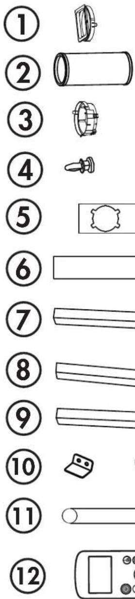
ACCESSORIES
- Air outlet adapter
- Exhaust hose
- Window slider adapter
- 2 Bolts
- Window slider A
- Window slider B and C
- Foam seal A (adhesive)
- Foam seal B (adhesive)
- Foam seal C (non-adhesive)
- Security bracket and 2 screws
- Drain hose
- Remote control and batteries
text_image
Diagram showing 12 numbered items with corresponding icons, likely illustrating a layout or labeling system.REQUIRED TOOLS
- Medium sized Phillips screwdriver
- Tape measure or ruler
- Knife or scissors
- Saw (in the event that the window sliders need to be cut to size)
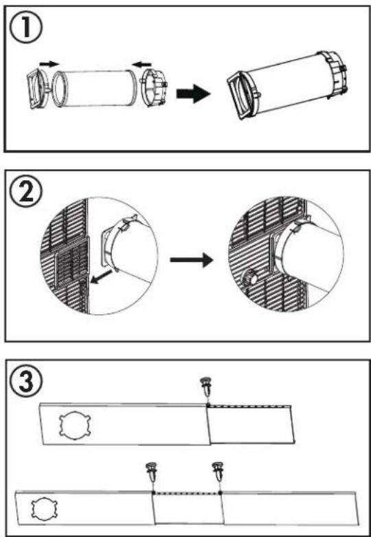
ASSEMBLING THE WINDOW KIT
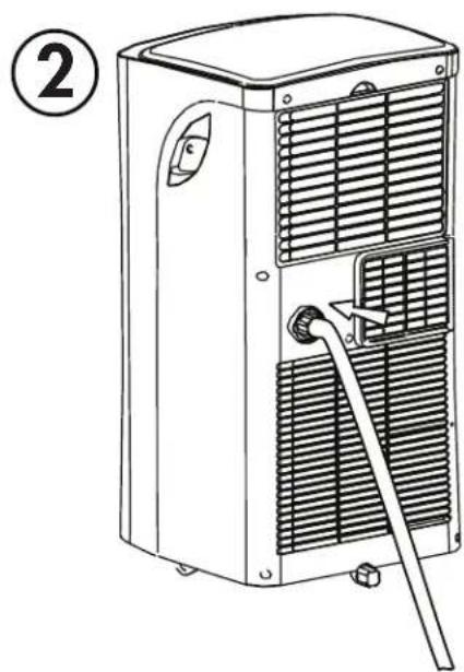
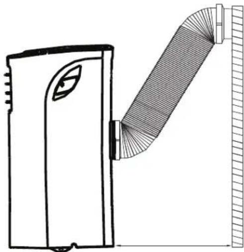
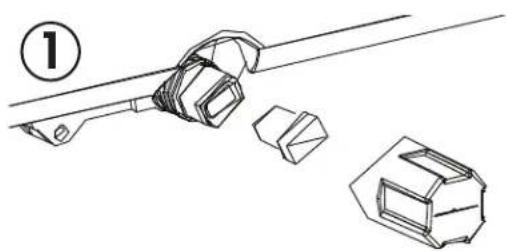
- Attach the air outlet adapter and the window slider adapter onto either end of the exhaust hose.
- Insert the air outlet adapter into the back of the appliance by placing over the air exhaust and then pushing in the direction of the arrow to lock into place.
- Measure the window opening where the window kit will be installed. Assemble as many sliders as necessary to fit the window. If the length of the window requires all three sliders, use two bolts to fasten the sliders at the correct length. If the window opening is less that the minimum length of a single slider, use the slider that has the hole in it and cut it to the correct length. Make sure not to cut the end that has the hole as this is necessary to attach the exhaust hose adapter.
text_image
Technical diagram illustrating three-step assembly steps of a cylindrical device, showing transformation from one to two and then to a final assembly.INSTALLATION INSTRUCTIONS
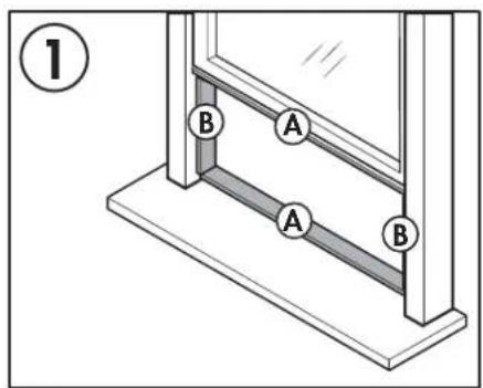
INSTALLING THE WINDOW KIT
The window kit can be used in either a hung window or a sliding window application. The images at the right are for a hung window. The steps for a sliding window are the same.
- Cut the adhesive foam seals A and B to the correct length for the window. Attach them to the window sash and frame as shown.
- Insert the assembled window slider kit into the window opening.
- Cut the non-adhesive foal seal C to match the width of the window. Insert the foam seal between the glass and the window frame to prevent air and insects from getting into the room.
- Attach the window slider adapter to the hole in the window slider kit.
Note: It may be easier to attach the window slider adapter to the window slider kit before placing the kit in the window.
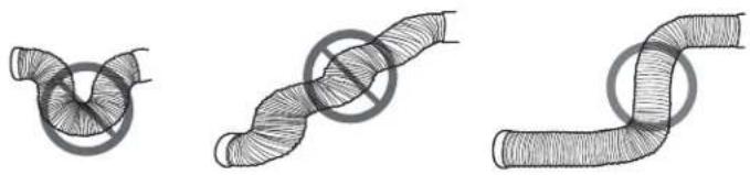
Note: Do not over extend or bend the hose as this will impede air flow.
natural_image
Three hand-drawn illustrations of pipe fittings with no text or symbolsIMPORTANT WARNING
Do not leave this appliance unattended in a space where people or animals who cannot react to a malfunction are located. A malfunction such as the exhaust hose becoming dislocated, can cause extreme overheating or death in an enclosed, unattended space.
text_image
① A B A B
natural_image
Line drawing of a window frame with a numbered label (2) and no text or symbols on the frame itself
natural_image
Line drawing of a window frame with a handle and a label '3' (no text or symbols on the diagram itself)
text_image
④
natural_image
Line drawing of a portable air conditioner unit next to a monitor (no text or symbols)OPERATING INSTRUCTIONS
FEATURES
Front
-
Handle (both sides)
-
Control panel
natural_image
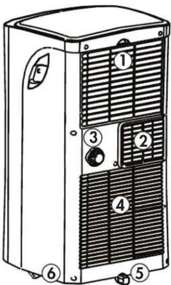
Line drawing of a portable air conditioner unit with labeled parts (1 and 2), no text or symbols present.Rear
- Upper air filter and air intake
- Air outlet
- Continuous drain outlet
- Lower air intake
- Drain outlet
- Casters
text_image
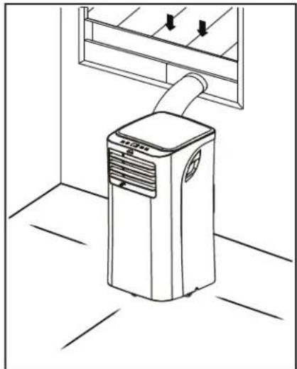
Technical diagram of a refrigerant unit with numbered components for identificationLOCATION
Place the air conditioner on a smooth, level floor that is strong enough to support it and all included accessories.
Make sure the appliance is level to minimize noise and vibration.
The appliance must be installed near a grounded receptacle and the overflow drain outlet on the rear of the appliance must be accessible.
Do not cover air inlets or outlets or the remote control receiver on the control panel.
The appliance requires 30 cm (12 inches) of clearance on the sides and 50 cm (20 inches) of clearance on the front.
natural_image
Line drawing of a small air conditioner unit mounted on a floor, with no text or symbols present.The appliance requires at least 50 cm (20 inches) of clearance on the back.
natural_image
Technical line drawing of a mechanical component with a curved pipe or duct assembly (no text or symbols)OPERATING INSTRUCTIONS
CONTROL PANEL
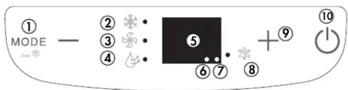
- Mode button:
- Press to select the desired mode.
- Press and hold for 3 seconds to activate the continuous fan.
- Cool mode indicator light: Illuminates when cooling mode is activated.
- Fan mode indicator light: Illuminates when fan mode is activated.
- Dry mode indicator light: Illuminates when dry mode is activated.
- LED Display: Shows the set temperature in °C or °F or the auto-timer settings.
- Power indicator light: Illuminates to indicate that the appliance has power.
- Timer indicator light: Illuminates when the timer is activated.
- Continuous fan indicator light: Illuminates when the continuous fan is activated.
- Temperature control buttons:
• Used to set the temperature. - Press and hold both temperature control buttons for 3 seconds to change the temperature display from °C to °F.
- Power Button: Press to turn the appliance on or off.
text_image
① MODE — ② ③ ④ ⑤ ⑥ ⑦ ⑧ +⑨ ⑩OPERATING MODES
Cool Mode
Choose cool mode to set the cooling function.
- Use the temperature control buttons to choose the desired temperature.
- Use the fan button to choose the desired fan speed.
- The temperature can be set within a range of 17 - 30°C (62 - 86°F).
- The exhaust hose should be installed during cool mode to ensure the best results.
Dry Mode
Choose dry mode to remove excess moisture from the air. Water will condense inside the appliance and drain out the back.
- The humidity level and fan speed will be automatically set and cannot be modified in dry mode.
- The exhaust hose does not need to be installed during dry mode.
- It may be necessary to install the continuous drain hose during dry mode to remove excess water.
Fan Mode
Fan mode can be used to run the fan without engaging the cooling or dehumidifying functions.
- Press the fan button to choose the desired fan speed.
- The exhaust hose does not need to be installed during fan mode.
- In cooling or dry mode, press and hold the mode button for 3 seconds to set the fan to run continuously. Press and hold the fan button for 3 seconds to disengage the continuous fan. During normal operation the fan will turn on and off with the compressor.
Auto Mode
Auto mode is a pre-set factory program that automatically defi nes the mode (cool or fan) and fan speed based on the set temperature and the ambient temperature. The exhaust hose should be installed during auto mode. Auto mode can only be activated from the remote control.
OPERATING INSTRUCTIONS
TIMER
Auto Off
- When the air conditioner is turned on, press the timer button to activate the auto off timer.
- Press the temperature control buttons to change the set time in 0.5 hour increments up to 10 hours and then in 1 hour increments up to 24 hours.
Auto On
- When the air conditioner is turned off, press the timer button to activate the auto on timer.
- Press the temperature control buttons to change the set time in 0.5 hour increments up to 10 hours and then in 1 hour increments up to 24 hours.
Using Auto On and Auto Off Together
The auto on and auto off timers can be used at the same time by first setting one and then the other.
For example, if the air conditioner is running, you can set the auto off timer to let it run for a set amount of time before turning off and then set the auto on timer to turn it back on at a later time.
Or, if the air conditioner is not running, you can set the auto on timer to turn it on at a later time and then set the auto off timer to shut it off after running for a period of time.
Note: The timer will not cycle the air conditioner on and off indefinitely. The auto on and auto off timers will function one time and then the air conditioner will return to regular functioning.
Turning the air conditioner on or off at any time or changing the timer setting to 0.0 will cancel the timer settings.
SHORTCUT FUNCTION
• Used to save a favourite setting.
- Set the appliance to the temperature and fan speed that you would like to set as a favourite.
- Press and hold the shortcut button for 2 seconds.
- Press the shortcut button at any point in future to return to the favourite setting.
- If no favourite is set, pressing the shortcut button will cause the appliance to run in auto mode at 29°C (79°F), with fan speed set to auto.
The shortcut function can only be activated with the remote control.
SLEEP FUNCTION
The sleep function can be used to conserve energy during sleeping hours. The sleep function can only be used during cool mode.
When selected, the set temperature will increase by 1 degree per hour for 2 hours. The appliance will hold the new set temperature for 6 hours before automatically returning to normal operation.
The sleep function can only be activated with the remote control and can be canceled at any time by pressing the sleep button.
OPERATING INSTRUCTIONS
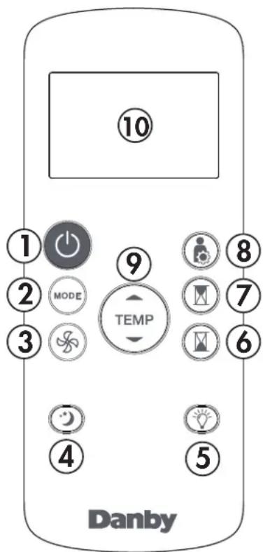
REMOTE CONTROL
- Power button: Press to turn the appliance on or off.
- Mode button: Press to select the desired mode.
- Fan button: Press to select fan speed.
- Sleep button: Press to start the sleep function.
- LED button: Press to turn the LED display on or off.
- Timer off button: Press to set the Auto-off timer.
- Timer on button: Press to set the Auto-on timer.
- Shortcut button: Press to set and activate the short cut function.
- Temperature control buttons:
• Used to set the temperature. - Press and hold both temperature control buttons for 3 seconds to change the temperature display from °C to °F.
- LED Display: Shows the set temperature in °C or °F or the auto-timer settings.
Note: The remote control can be used at a maximum distance of 8 meters (26 feet) from the appliance. Using the remote control more than 8 meters (26 feet) away from the appliance can result in poor reception of the signal.
text_image
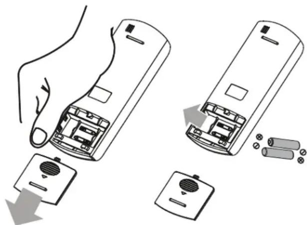
10 ① ② MODE ③ ④ ⑤ TEMP ⑥ ⑦ ⑧ DanbyREPLACING THE REMOTE BATTERIES
This air conditioner comes with two AAA batteries. Place the batteries in the remote control before use.
- Slide the back cover from the remote downward to expose the battery compartment.
- Insert the batteries, ensure to match the (+) and (-) symbols on the ends of the batteries with the symbols inside the battery compartment.
- Slide the battery cover back into place.
Notes:
- The air conditioner will not respond if curtains, doors or other materials block the signal from the remote control to the unit.
- Prevent any liquid from contact with the remote control. Do not expose the remote control to direct sunlight or heat.
- If the infrared signal receiver on the indoor unit is exposed to direct sunlight, the air conditioner may not function properly. Use curtains to prevent the sunlight from falling on the receiver.
- Do not mix old and new batteries or batteries of different types.
- Do not leave the batteries in the remote control if it is not going to be used for more than 2 months.
natural_image
Illustration of a hand holding an open remote control case with battery and battery pack components (no text or symbols)IMPORTANT
Do not dispose of batteries as unsorted municipal waste. Refer to local laws for proper disposal of batteries.
OPERATING INSTRUCTIONS
REMOTE CONTROL REGULATIONS
This equipment has been tested and found to comply with the limits for a Class B digital device, pursuant to Part 15 of the FCC Rules. These limits are designed to provide reasonable protection against harmful interference in a residential installation. This equipment generates, uses and can radiate radio frequency energy and, if not installed and used in accordance with the instructions, may cause harmful interference to radio communications. However, there is no guarantee that interference will not occur in a particular installation.
If this equipment does cause harmful interference to radio or television reception, which can be determined by turning the equipment off and on, the user is encouraged to try to correct the interference by one or more of the following measures:
- Reorient or relocate the receiving antenna
- Increase the separation between the equipment and receiver
- Connect the equipment into an outlet on a circuit different from that to which the receiver is connected
- Consult the dealer or an experienced radio/TV technician for help
Changes or modifications not approved by the party responsible for FCC and Industry Canada compliance could void the user's authority to operate the equipment. This appliance complies with Part 15 of the FCC Rules and license-exempt RSS standards.
Operation is subject to the following conditions:
- This device may not cause interference.
- This device must accept any interference received, including interference that may cause undesired operation.
This equipment complies with FCC RF and IC RSS-102 radiation exposure limits set forth for an uncontrolled environment. This equipment should be installed and operated with minimum distance 20 cm (8 inches) between the radiator and your body.
This device complies with RSS-247 of Industry Canada. Operation is subject to the condition that this device does not cause harmful interference. This device complies with Canadian CAN ICES-003(B)/NMB-003(B)
This device contains:
FCC ID: 2ADQOMDNA21
IC: 12575A-MDNA21
SUPPLIER'S DECLARATION OF CONFORMITY
47 CFR § 2.1077 Compliance Information
Unique Identifi er: Danby, RG57H1(B)/BGCE-M
Responsible Party U.S. Contact Information:
Danby Products Inc.
1800 Production Drive
Findlay, OH
45840
Telephone number or internet contact information: Danby.com
FCC Compliance Statement: This appliance complies with Part 15 of the FCC Rules. Operation is subject to the following conditions:
- This device may not cause interference.
- This device must accept any interference received, including interference that may cause undesired operation.
OPERATING INSTRUCTIONS
WATER DRAINAGE
Ensure the air conditioner is turned off and unplugged and that it is close to a floor drain before setting up any drain option.
1. Drain Plug
When the internal drain pan becomes full the appliance will beep 8 times and the digital display will show error code P1. The air conditioning or dehumidifying action will stop but the fan may continue to operate.
Remove the drain plug and allow the water to completely drain. Replace the bottom drain plug, pressing firmly to ensure a tight fit and no leaks.
2. Continuous Drain
During dry mode, you may wish to install a continuous drain option so that the air conditioner will automatically drain collected water.
Remove the upper drain plug and attach the drain hose that was provided with the air conditioner. Place the open end of the drain hose over the receptacle that it will drain into; this could be a basement floor drain, a sink or similar.
Ensure that there are no kinks or bends in the drain hose and that it goes straight down toward the floor. The continuous drain is activated by gravity only. If the hose is not positioned directly downwards, water will not drain correctly.
natural_image
Technical line drawing of a mechanical component with two views and a numbered label (1), no readable text or symbols present.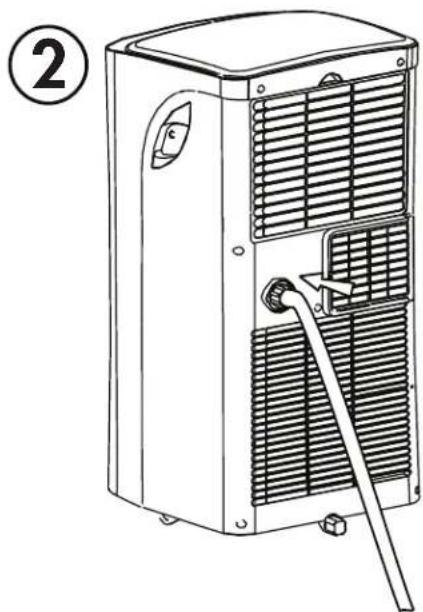
natural_image
Line drawing of a portable air conditioner unit with cooling fins and a handle (no text or symbols)CARE & MAINTENANCE
CLEANING
- Unplug the appliance before cleaning or servicing.
- Clean the cabinet with a lukewarm damp cloth and neutral detergent. Dry the cabinet with a lint-free dry cloth.
- Do not use gasoline, paint thinner or other chemicals to clean the appliance.
- Do not wash the appliance directly under a tap or using a hose. It may cause electrical damage.
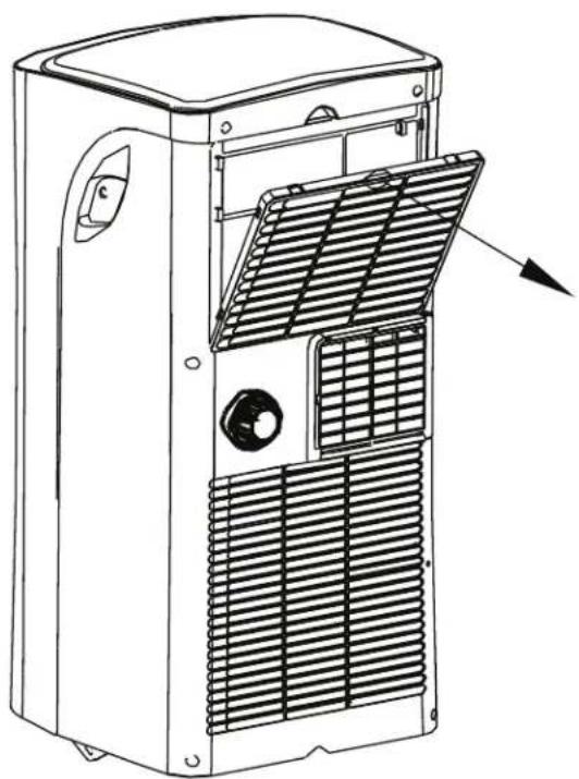
AIR FILTER
The air fi lter should be cleaned every two weeks to ensure effi cient performance.
In households with animals, the air filters may need to be cleaned more often and the external grills may need to be wiped to prevent blocked air flow.
natural_image
Line drawing of a refrigerated industrial air conditioner unit with cooling fins and ventilation slots (no text or symbols)LONG-TERM STORAGE
- Drain all water from the appliance.
- Run the appliance on Fan mode for half a day in a warm room to dry the inside of the appliance and prevent mold formation.
- Turn off the appliance and unplug it, wrap the cord and bundle it with tape.
- Remove the batteries from the remote control.
- Clean the air filters and reinstall them.
- Store the appliance in a cool, dark place. Prolonged exposure to direct sunlight or extreme heat can shorten the lifespan of the appliance.
DISPOSAL
This appliance should not be treated as regular household waste. Check for local regulatory compliance regarding the approved and safe disposal of this appliance.
ERROR CODES
E1 - room temperature sensor error
E2 - evaporator temperature sensor error
E4 - display panel communication error
P1 - water tray is full - attach drain hose and drain excess water
FREQUENTLY ASKED QUESTIONS TROUBLESHOOTING
Can I leave my air conditioner in place through the winter?
No, it is not recommended to leave the window kit in place during the winter.
What are the watts and amps used?
This information can be found on the rating plate located on the side of the unit.
Can I use an extension cord?
No, an extension cord may not be used.
When should I use the exhaust hose?
The exhaust hose should be used in cool, heat and auto modes. It is not required in fan and dry modes.
Can I extend the length of the exhaust hose?
No, extending the length of the exhaust hose can actually cause the air conditioner to run less efficiently. Instead use an additional fan to blow the cool air to other locations.
When should I use the drain hose?
The drain hose should be used in heat mode, dry mode or if using the continuous drain.
Where do I drain water from?
There are two different drain options on this air conditioner, please refer to the water drainage section.
Air conditioner will not operate
- Plug is not fully inserted into the wall outlet.
- Blown fuse or circuit breaker.
Insuffi cient cooling
- Air filter is dirty.
- Blocked air flow.
- Appliance size is too small for application.
Noise
- The ground is not level.
• The air fi lter is dirty or blocked. - Gurgling sounds are normal, this is coolant moving inside the appliance.
Odors
• Usually caused by the formation of mold or mildew on internal wet surfaces.
- Ensure the filter is clean.
- Run the air conditioner on fan mode to remove any internal moisture.
- Check for any blockages in the drain lines and ensure there are no obstructions.
- Place an algaecide tablet in the base pan; ensure the appliance is unplugged, remove the upper grille and fi liter, place the tablet in the middle water tray and replace the grille and fi liter
LIMITED APPLIANCE WARRANTY
This quality product is warranted to be free from manufacturer's defects in material and workmanship, provided that the unit is used under the normal operating conditions intended by the manufacturer.
This warranty is available only to the person to whom the unit was originally sold by Danby Products Limited (Canada) or Danby Products Inc. (U.S.A.) (hereafter "Danby") or by an authorized distributor of Danby, and is non-transferable.
TERMS OF WARRANTY
Plastic parts, are warranted for thirty (30) days only from purchase date, with no extensions provided.
First Year
During the first twelve (12) months, any functional parts of this product found to be defective, will be repaired or replaced, at warrantor's option, at no charge to the ORIGINAL purchaser.
To obtain Service
It will be the consumer's responsibility to transport the appliance (at their own expense) to a service depot for repair. Contact your nearest authorized Danby service depot, where service must be performed by a qualified service technician. If service is performed on the unit by anyone other than an authorized service depot, or the unit is used for commercial application, all obligations of Danby under this warranty shall be void.
Nothing within this warranty shall imply that Danby will be responsible or liable for any spoilage or damage to food or other contents of this appliance, whether due to any defect of the appliance, or its use, whether proper or improper.
EXCLUSIONS
Save as herein provided, by Danby, there are no other warranties, conditions, representations or guarantees, express or implied, made or intended by Danby or its authorized distributors and all other warranties, conditions, representations or guarantees, including any warranties, conditions, representations or guarantees under any Sale of Goods Act or like legislation or statute is hereby expressly excluded. Save as herein provided, Danby shall not be responsible for any damages to persons or property, including the unit itself, howsoever caused or any consequential damages arising from the malfunction of the unit and by the purchase of the unit, the purchaser does hereby agree to indemnify and hold harmless Danby from any claim for damages to persons or property caused by the unit.
GENERAL PROVISIONS
No warranty or insurance herein contained or set out shall apply when damage or repair is caused by any of the following:
1) Power failure.
2) Damage in transit or when moving the appliance.
3) Improper power supply such as low voltage, defective house wiring or inadequate fuses.
4) Accident, alteration, abuse or misuse of the appliance such as inadequate air circulation in the room or abnormal operating conditions (extremely high or low room temperature).
5) Use for commercial or industrial purposes (ie. If the appliance is not installed in a domestic residence).
6) Fire, water damage, theft, war, riot, hostility, acts of God such as hurricanes, floods etc.
7) Service calls resulting in customer education.
8) Improper Installation (ie. Building-in of a free standing appliance or using an appliance outdoors that is not approved for outdoor application). Proof of purchase date will be required for warranty claims; so, please retain bill of sale. In the event warranty service is required, present this document to our AUTHORIZED SERVICE DEPOT.
Warranty Service
Carry-In
text_image
Warning sign depicting a flame symbol in a triangular shape, indicating hazard or caution.ATTENTION: RISQUE D'INCENDIE
natural_image
Simple line drawing of a pencil with a numbered circle (7) beside it, no text or symbols present.
natural_image
Simple line drawing of a pencil with a circled number 9 beside it (no text or symbols on the pencil itself)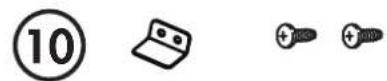
natural_image
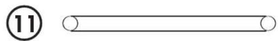
Simple line drawing of a cylindrical object with a number 11 beside it (no text or symbols on the object itself)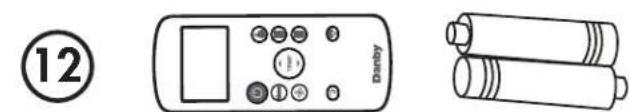
text_image
12 DanbyOUTILS REQUIS
natural_image
Three hand-drawn diagrams of pipe fittings with no text or symbolsAVERTISSEMENT IMPORTANT
natural_image
Line drawing of a window frame with a label circled (2), showing no text, numbers, or symbols on the frame itself.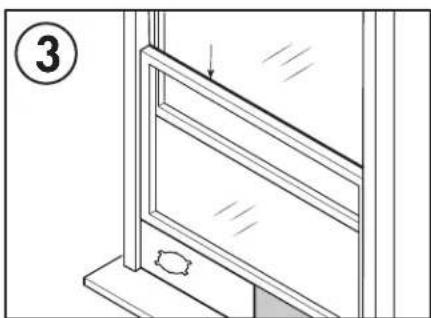
natural_image
Line drawing of a window frame with a handle and a label '3' (no text or symbols on the diagram itself)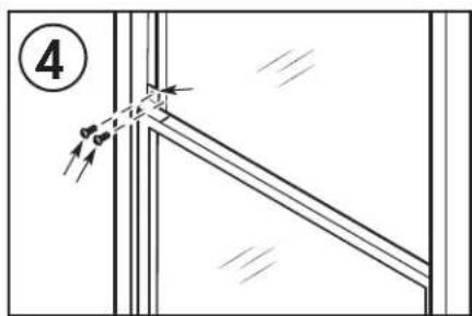
text_image
④
natural_image
Line drawing of a portable air conditioner unit next to a monitor (no text or symbols)INSTRUCTIONS D'UTILISATION
CARACTÉRISTIQUES
Avant
natural_image
Line drawing of a portable air conditioner unit with labeled parts (1 and 2), no text or symbols present.Arrière
text_image
Technical diagram of a refrigerant unit with numbered components for identificationEMPLACEMENT
natural_image
Line drawing of a small air conditioner unit with airflow direction arrows (no text or symbols)natural_image
Technical line drawing of a mechanical component with a curved pipe or duct assembly (no text or symbols)INSTRUCTIONS D'UTILISATION
PANNEAU DE CONTRÔLE
natural_image
Illustration of a hand holding a remote control casing with battery and switch components, showing internal components and directional arrows (no text or symbols)IMPORTANT
natural_image
Technical line drawing of a mechanical component with two views and a numbered label (1), no readable text or symbols present.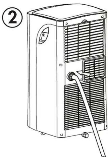
natural_image
Line drawing of a portable air conditioner unit with cooling fins and a handle (no text or symbols)SOINS ET MAINTENANCE
NETTOYAGE
natural_image
Line drawing of a refrigerant air conditioner unit with cooling fins and ventilation slots (no text or symbols)ENTREPOSAGE À LONG TERME
text_image
Warning sign depicting a flame symbol in a triangular frame, indicating hazard or caution.text_image
Diagram showing 12 numbered items with corresponding icons, likely illustrating a sequence of mechanical or electrical components.natural_image
Three hand-drawn pipe illustrations showing different types of pipe connections (no text or symbols)ADVERTENCIA IMPORTANTE
natural_image
Line drawing of a window frame with a label circled (2), showing no text, numbers, or symbols on the frame itself.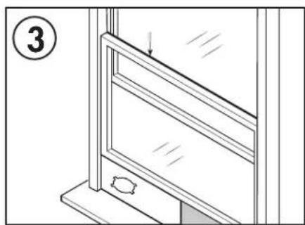
natural_image
Line drawing of a window frame with a door and an arrow indicating direction (no text or symbols)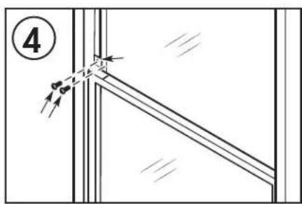
text_image
④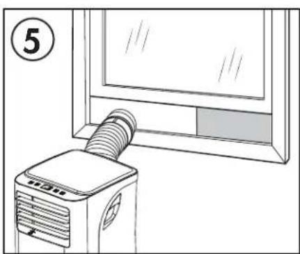
natural_image
Line drawing of a portable air conditioner unit next to a monitor (no text or symbols)natural_image
Line drawing of a portable air conditioner unit with labeled parts (1 and 2), no text or symbols present.Posterior
text_image
Technical diagram of a multi-chamber air conditioning unit with numbered components and labeled partsUBICACIÓN
natural_image
Line drawing of a small air conditioner unit mounted on a wall, with no text or symbols present.natural_image
Technical line drawing of a mechanical component with a curved pipe or rod extending from its side, showing internal structure and dimension lines (no text or symbols)natural_image
Illustration of a hand holding an open remote control with battery and switch components (no text or symbols)IMPORTANTE
natural_image
Technical line drawing of a mechanical component with two views and a separate 3D block structure (no text or symbols)