FMF 3545 - Smoke detector GEV - Free user manual and instructions
Find the device manual for free FMF 3545 GEV in PDF.


User questions about FMF 3545 GEV
0 question about this device. Answer the ones you know or ask your own.
Ask a new question about this device
Download the instructions for your Smoke detector in PDF format for free! Find your manual FMF 3545 - GEV and take your electronic device back in hand. On this page are published all the documents necessary for the use of your device. FMF 3545 by GEV.
USER MANUAL FMF 3545 GEV
natural_image
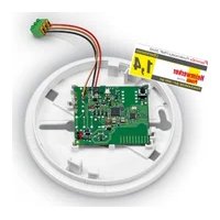
Technical line drawing of a circular mechanical or electrical component with internal components and wiring, labeled FMF 3545 (no text or symbols on the diagram itself)
03545
GEV
text_image
1 2 3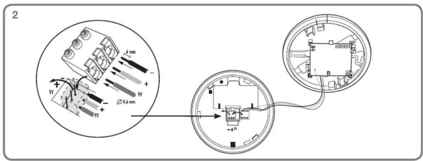
text_image
2 9V 6 mm + 9V Ø 0,6 mm 9V -45V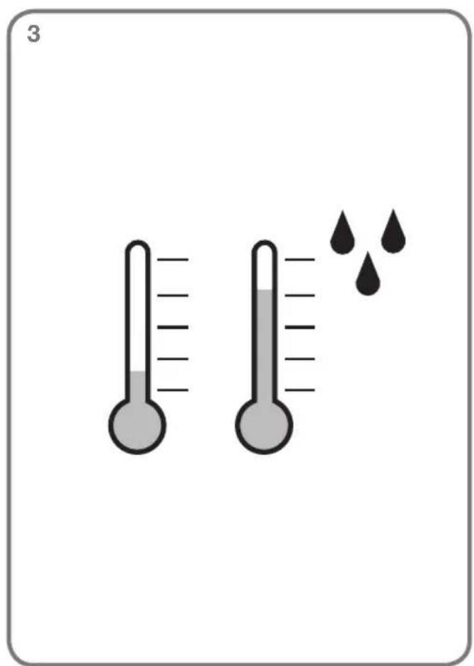
text_image
3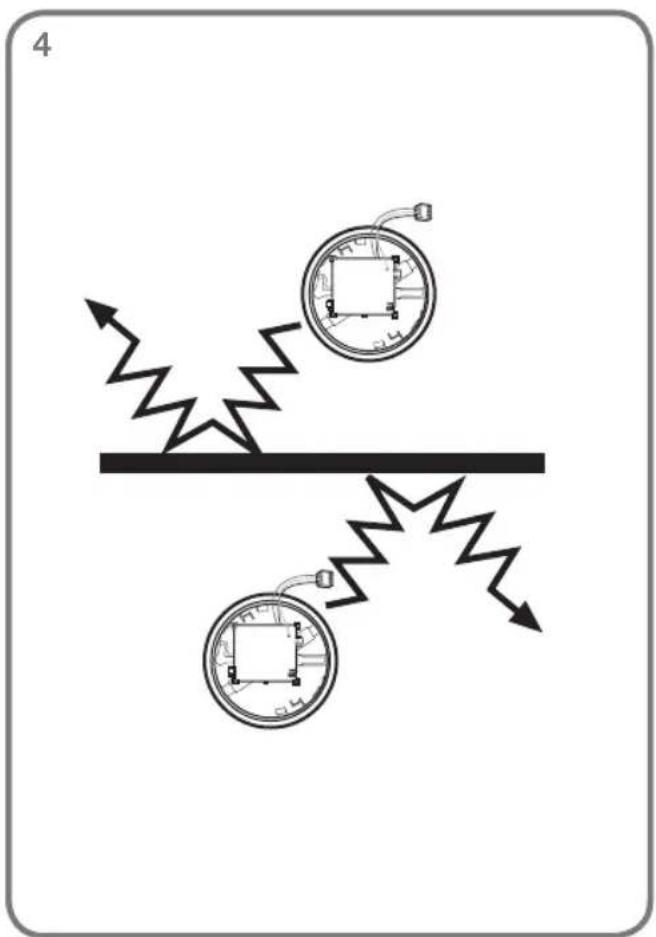
text_image
4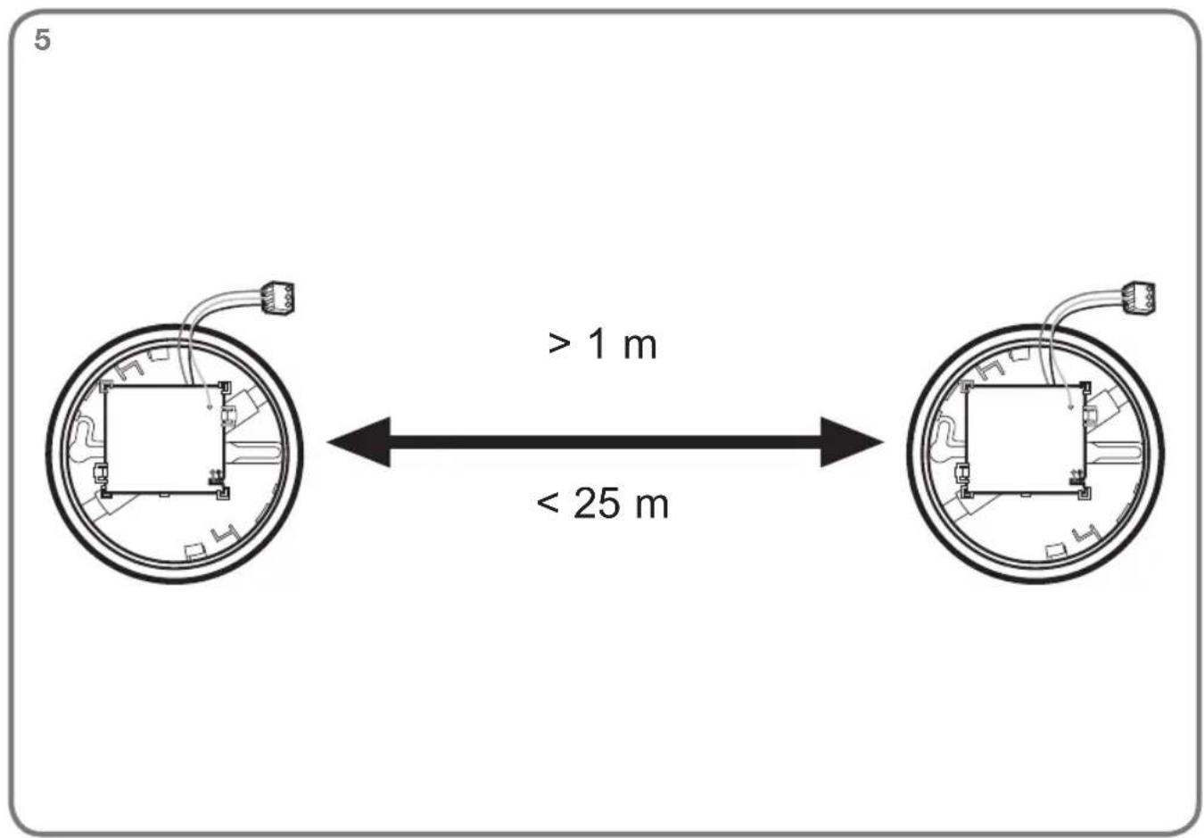
text_image
5 > 1 m < 25 m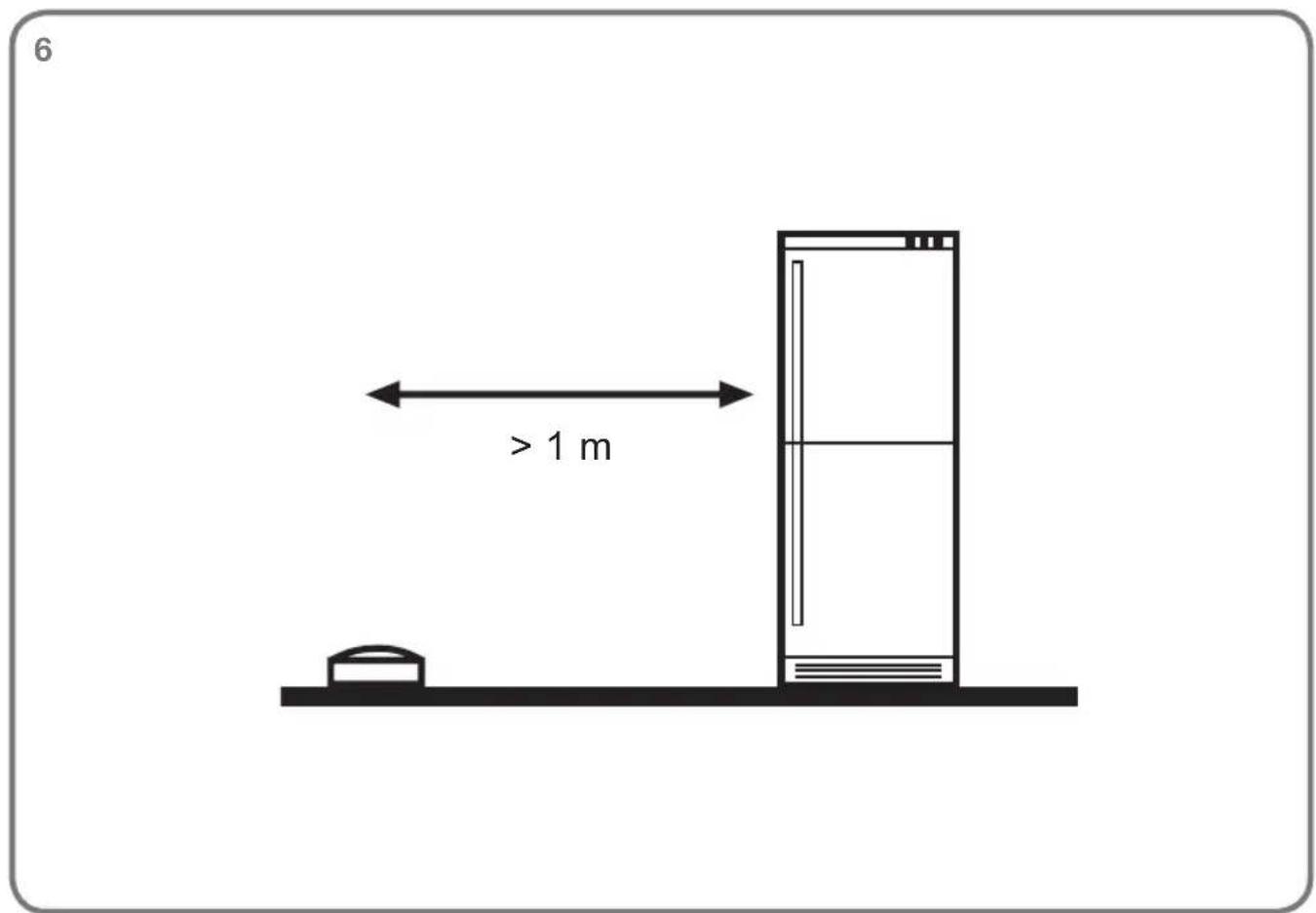
text_image
6 > 1 m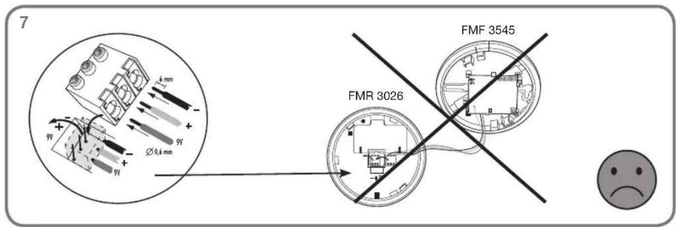
text_image
7 9V 6 mm 9V Ø0,6 mm 9V FMR 3026 FMF 3545 -9V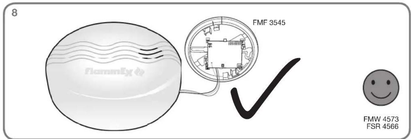
text_image
8 FMF 3545 FMW 4573 FSR 4566Please read carefully and retain! In buying this item you have opted for a high-quality FlammEx product. Please read these user instructions carefully to ensure the device is used correctly. Keep them in a safe place for future reference. Use this product only as intended (as set out in the user instructions). Any changes or modifications to the product or painting it will result in loss of warranty.
Product description
The retrofittable radio module sends and receives alarm signals in conjunction with other radio-networking FlammEx products if they also have an FMF 3545. As soon as an alarm via the network terminal emits, the radio module sends the alarm via radio to all radio modules in its radio group. This process involves the radio modules that are in range forwarding an alarm message within the respective radio group once. This alarm message even bypasses transmission paths that are particularly long, such as from the basement to the top floor via the ground floor, for example. When the alarm is no longer active at the original triggering device, the radio modules cancel the alarm after a short time (up to approximately 30 seconds). Up to 30 radio modules with smoke detectors can be assigned to a radio group. Up to eight independent radio groups can be programmed so that modules do not interfere with each other within blocks of flats, for example. The radio modules assigned to the same radio group must only be located within one building. It is not permitted to install some of the radio modules in neighbouring buildings.
Operation/testing
Each detector/radio module that receives a radio signal directly from the signal origin in the same radio group forwards this signal forwards once automatically. To avoid data collision, the signal is forwarded only when the radio channel is free. Each detector sending a signal acknowledges that the signal has been forwarded by emitting 3-4 short sounds at intervals of approximately five seconds. When the channel is free again, the next detector/radio module forwards the signal and acknowledges it, and so on. When a battery is drained, this is displayed locally on the host device, as described in its instructions. In addition, the radio module automatically measures the battery approximately every 20 minutes. The drained threshold value is set to approximately 6.9 V, so that the message will be sent only after the fault message is displayed by the host device itself. Each detector sending a battery signal acknowledges that the signal has been forwarded by emitting 3-4 short sounds at intervals of approximately five seconds. When the channel is free again, the next detector/radio module forwards the signal and acknowledges it, and so on.

Note: Follow the instructions for the host device.
Programming/commissioning

Note: We recommend programming the radio modules before installing the equipment on the ceiling.
At any one time, activate only the two radio modules that are to be programmed and not every module simultaneously. To ensure that the other radio modules remain deactivated, remove the three-pin terminal of the radio module (Fig. 1.3) from the host device or disconnect the battery for all other modules.
- The radio module and the host device share the same battery. Sharing the battery means that the battery life is reduced.
- Close the battery compartment of the host device. The red LED on the host device flashes briefly approximately every 45 seconds to indicate that the battery is fitted correctly.
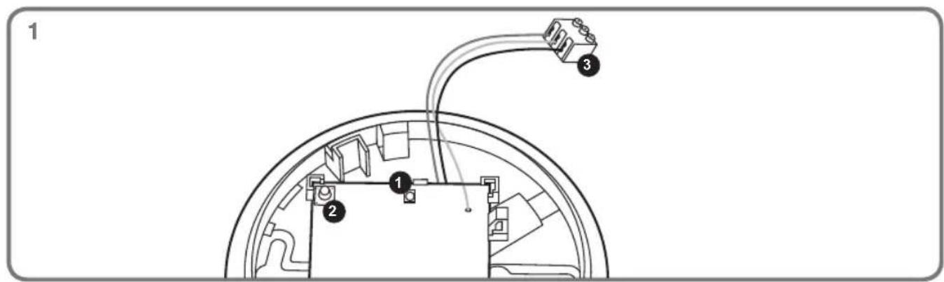
- Connect the radio module to the host device. To do this, plug the three-pin terminal of the radio module (Fig. 1.3) onto the host device. (For smoke detectors, you must first disconnect the green terminal from the smoke detector.) Carefully plug in the terminal fully by inserting it as far as it will go until it is flush with the housing of the host device. The radio module acknowledges that the terminal has been connected correctly with a short flash of the red LED (Fig. 1.1). The host device may emit a short beeping sound when the terminal is being plugged in. If the terminal is attached incorrectly, smoke detectors triggers an alarm immediately. Do not close the lid yet, as the radio module must be programmed first.

Note: Maintain a minimum distance of one metre between the radio modules, even during installation.
Creating a radio group
At any one time, activate only the two radio modules that are to be programmed and not every module simultaneously. Hold down the button (Fig. 1.2) on a radio module for approximately 2–3 seconds. The red LED (Fig. 1.1) then begins to flash approximately once every second. Release the button again. The radio module enters programming mode for approximately 60 seconds. After this period, immediately press the button (Fig. 1.2) on another radio module for approximately 2–3 seconds. The red LED (Fig. 1.1) then begins to flash approximately once every second. Release the button again. The radio module enters programming mode for approximately 60 seconds. During this time, both radio modules reciprocally program themselves into a radio group automatically. The programming process can take up to approximately 60 seconds in total. If programming was successful, the red LEDs (Fig. 1.1) on both radio modules light up permanently for 2–3 seconds. If after approximately 60 seconds the red LEDs do not light up permanently for 2–3 seconds, the programming process was not successful and the radios modules return to normal mode. In this event, the programming process must be repeated. Up to 30 radio modules can be assigned to a radio group.
Expanding an existing radio group
At any one time, activate only the two radio modules that are to be programmed and not every module simultaneously. To expand an existing radio group, switch any radio module from the radio group to be expanded to the programming mode by holding down the button (Fig 1.2) for approximately 2–3 seconds. For the other radio modules, do not plug the three-pin terminals of the radio modules (Fig. 1.3) onto the detector. The red LED (Fig. 1.1) then begins to flash approximately once every second. Release the button again. The radio module enters programming mode for approximately 60 seconds. After this period, immediately press the button of the radio module to be added for approximately 2–3 seconds. The red LED then begins to flash approximately once every second. Release the button again. The radio module enters programming mode for approximately 60 seconds. During this time, the radio module to be added will be automatically incorporated into the existing radio group. The programming process can take up to approximately 60 seconds in total.
Creating an additional radio group
At any one time, activate only the two radio modules that are to be programmed and not every module simultaneously. Proceed in the same manner as described in the section entitled „Creating a radio group“. Program only the radio modules to be incorporated into the additional radio group. During this process, do not integrate a radio module that is already assigned to another radio group. It is possible to create up to eight independent radio groups.

Note: The button (Fig. 1.2) is locked for five minutes after being activating. This also applies for the radio modules that have received the test radio message.
Deleting programmed settings/factory setting
Press and hold down the button (Fig. 1.2) on the radio module that you want to delete for approx. 5 seconds until the red LED (Fig. 1.1) starts flashing approx. twice per second. When you have held the button down for approx. 2-3 seconds, it will initially start flashing approx. once per second. Continue to hold down the button until the LED starts flashing twice as fast. Release the button. The radio module confirms deletion by emitting a short beep and then returns to standard mode. However, the device does not belong to a radio group.
Installation

Note: Follow the instructions for the host device.
Avoid damp environments and extreme temperatures (Fig. 3). Note that metal surfaces and walls containing metal can severely dampen or reflect the radio signals (Fig. 4). Maintain a minimum distance of one metre between the radio modules (Fig. 5) during installation. Maintain a minimum distance of one metre from large appliances (Fig. 6).
- Follow the instructions for the host device when determining the installation location.
- Plug the three-pin terminal of the radio module (Fig. 1.3) onto the underside of the device (Fig. 2).
- Close the lid of the device. (Special feature of smoke detectors: If a battery is not inserted into the smoke detector, it is not possible to lock the smoke detector in place on the radio module.)

Note: Make sure that the connection wires are not routed over the circuit board of the radio module — instead, they must be routed directly from the edge of the housing to the three-pin plug on the radio module
- Once all radio modules/host devices are installed, perform a function test for example by pressing the test button on the smoke detector until the smoke detector emits alarm sounds or provoke a false alarm. (When performing the function test, follow the instructions for the host device.) The radio modules/ or the devices equipped with it of the same radio group signal the alarm acoustically and automatically return to normal mode after a short period of time. If a detector forwards the OUT signal, it acknowledges that it has done so by emitting three short sounds. See the section entitled „Operation/testing“.
The device is approved for operation inside the European Community.
GEV GmbH hereby declares that this device (Radio Transmit and Receive Module FMF 3545) accords with the fundamental requirements and the other relevant regulations of guideline 1999/5EG. The full declaration of conformity can be seen under: www.gev.de
Recycling guidelines:

This device must not be disposed of as unsorted household waste. Used devices must be disposed of correctly. Contact your local town council for more information.
Technical data:
Type designation FMF 3545
Frequency 0 - 868 MHz
Operating voltage 9 V from the host device
Working temperature range 0 - 40°C
Relative humidity 0 - 90% non-condensing
Dimensions ∅ 106 mm, height 12 mm
Colour
white
Technical and design features may be subject to change.
text_image
GBFR T DECE

GEV GmbH
Heidehofweg 16
25499 Tangstedt
Germany
www.gev.de
service@gev.de
Hotline: +49 (0)180/59 58 555
International calls may vary.