HALion 4 - Audio software STEINBERG - Free user manual and instructions
Find the device manual for free HALion 4 STEINBERG in PDF.


| Product type | Sampler / virtual synthesizer software |
| Version | HALion 4 |
| Brand | Steinberg |
| Operating systems | Windows Vista / 7, Mac OS X 10.6 or later |
| Minimum processor | Pentium / Athlon 2.0 GHz dual-core (Windows); Intel Core Duo 2.0 GHz (Mac) |
| Minimum RAM | 2 GB |
| Required disk space | Approximately 15 GB (including content) |
| Recommended screen resolution | 1280 x 800 pixels |
| Copy protection | USB-eLicenser (sold separately) |
| Plugin formats | VST2, VST3, AU (Audio Unit) |
| Operating modes | Plugin (compatible host) or standalone |
| Maximum audio outputs | 32 stereo outputs + 1 5.1 output |
| Number of program slots | 64 |
| Included sound library | Over 1,600 instruments and patches (including those from HALion Sonic) |
| Audio engines | Sampling + virtual analog synthesis |
| Main functions | Program, layer, and zone editing; programming tree; integrated mixing console; studio effects; MIDI modules (FlexPhraser, MegaTrig, etc.); sample mapping and editing; automation; quick controls |
| Import formats | Apple EXS, GigaSampler, Kontakt, HSB files, FXP/FXB, REX, General MIDI |
| Export formats | VST Preset (.vstpreset), VST Sound, multi-programs with samples |
| Maintenance and cleaning | No hardware maintenance required; regular updates recommended via Steinberg |
| Security | Protection by USB-eLicenser; regularly back up your projects and presets |
| Spare parts and repairability | Downloadable software; USB-eLicenser key replacement possible |
| General information | Release date: May 31, 2011; manual available in French, English, German, Japanese |
Frequently Asked Questions - HALion 4 STEINBERG
User questions about HALion 4 STEINBERG
0 question about this device. Answer the ones you know or ask your own.
Ask a new question about this device
Download the instructions for your Audio software in PDF format for free! Find your manual HALion 4 - STEINBERG and take your electronic device back in hand. On this page are published all the documents necessary for the use of your device. HALion 4 by STEINBERG.
USER MANUAL HALion 4 STEINBERG
natural_image
Red circular icon with four triangular arrows pointing outward, no text or symbols present.HALION4
VST Sampler & Sound Creation System

natural_image
Abstract circular graphic with blue gradient center and white crosshair lines, no text or symbols presentEnglish
Matthias Klag, Michael Ruf
Revision and quality control: Cristina Bachmann, Heiko Bischoff, Marion Bröer, Sabine Pfeifer, Heike Schilling, Benjamin Schütte
This PDF provides improved access for vision-impaired users. Please note that due to the complexity and number of images in this document, it is not possible to include text descriptions of images.
The information in this document is subject to change without notice and does not represent a commitment on the part of Steinberg Media Technologies GmbH. The software described by this document is subject to a License Agreement and may not be copied to other media except as specifically allowed in the License Agreement. No part of this publication may be copied, reproduced, or otherwise transmitted or recorded, for any purpose, without prior written permission by Steinberg Media Technologies GmbH. Registered licensees of the product described herein may print one copy of this document for their personal use.
Steinberg, HALion, VST, and ASIO are registered trademarks of Steinberg Media Technologies GmbH. Windows 7, Windows Vista and DirectX are registered trademarks of Microsoft Corporation in the United States and other countries. Macintosh, Mac, Mac OS, and Logic are trademarks of Apple Inc., registered in the U.S. and other countries. Pentium and Intel Core are trademarks or registered trademarks of Intel Corporation in the U.S. and other countries. All other product and company names are ^™ or ^® trademarks of their respective holders.
Release Date: May 31, 2011
© Steinberg Media Technologies GmbH, 2011.
All rights reserved.
Table of Contents
7 Installation and Setup
8 Welcome
8 Key Command Conventions
8 How You Can Reach Us
9 Installation
10 Setting Up
12 The HALion Control Panel
13 Introduction
13 Configuring the Control Panel
14 Setting the Focus
15 Working with Multiple Windows
15 Screen Sets
16 Overview of the Available Editors
17 Macro Pages
18 Managing Your Sounds
19 The Slot Rack
21 Managing Multis
22 Managing Files via the MediaBay
25 Content Files and Folder Structure
25 Loading HALion 3 Programs
26 Working with General MIDI Files
27 Loading and Managing Programs
28 Introduction
28 The Columns of the Program Table
28 Loading Programs into the Program Table
29 Loading Programs from the Program Table to the Slot Rack
29 Editing the Program Table
30 Using the Program Tree
31 Introduction
31 The Program Tree Structure
32 Editing Zones, Programs, and Layers
33 Making Selections
34 Navigating in the Program Tree
34 Muting, Soloing, and Hiding
36 Adding MIDI Modules
36 Adding Insert Effects
36 Changing the Order of MIDI Modules and Insert Effects
36 Adding Audio Busses
36 Customizing the Program Tree
38 Global Functions and Settings
39 Introduction
39 The Plug-in Functions Section
40 The Toolbar
41 The Keyboard Editor
42 The Options Editor
45 Quick Controls
48 AI-Knob Support
49 Common Editing Methods
50 Introduction
50 Using Controls in HALion
51 Using Key Commands
51 Working with Presets
52 Using Automation
53 Using Effects
54 Using MIDI Modules
55 Importing and Exporting Samples
56 Importing Samples
58 Finding Missing Samples
59 Exporting Samples
61 Replacing Samples
62 Importing Third-Party Sampler Programs
63 Importing Sliced Loops
66 Editing Programs and Layers in the Sound Editor
67 Introduction
67 The Main Section
67 The Trigger Section
69 The Voice Management Section
71 The Variation Groups Section
72 The Quick Control Assignments Section
72 The Note Expression Section
74 Editing Zones in the Sound Editor
75 Introduction
75 Global Zone Settings
75 Editing Selected Zones or All Zones
75 Absolute and Relative Editing
75 HALion 3 compatibility
76 The Voice Control Section
78 The Pitch Section
78 The Oscillator Section
80 The Sample Oscillator Section
81 The Filter Section
84 The Amplifier Section
85 The Envelope Section
89 The LFO Section
91 The Step Modulator Section
92 The Modulation Matrix Section
97 Mapping Zones
98 Introduction
98 The Mapping Editor
101 Mapping Zones
102 Filling Gaps between Zones
102 Setting the Root Key
102 Selecting Zones with the Mapping Editor Keyboard
103 Editing Samples in the Sample Editor
104 Introduction
104 Overview
105 The Parameter Section
105 General Operations
108 Creating Loops
112 MIDI Editing and Controllers
113 The MIDI Editor
114 Using MIDI Controllers
114 Assigning MIDI Controllers
114 Assigning MIDI Controllers to AUX FX
114 Saving a MIDI Controller Mapping as Default
115 Automation and Factory MIDI Controller Assignments
115 CC 121 Support
116 Mixing and Routing
117 The Audio Bus Architecture
119 The HALion Mixer
122 Effects Reference
123 Introduction
123 Reverb and Delay Effects
126 EQ Effects
127 Distortion Effects
128 Modulation Effects
131 Dynamics Effects
134 Panner and Routing Effects
135 HALion 3 Legacy Effects
140 MIDI Modules Reference
141 Introduction
141 The FlexPhraser
144 The Trigger Pads
145 Mono Envelope
147 Mono LFO
148 MegaTrig
150 Layer Alternate
151 Key Switch Alternate
152 Key Switch Remote
153 MIDI Randomizer
154 True Pedaling
154 CC Mapper
155 Velocity Curve
156 Tuning Scale
157 Key Commands Reference
158 The Default Key Commands
159 Using the HALion Standalone Version
160 Introduction
160 Making Preferences Settings
161 Selecting the MIDI Input and the Audio Output
161 The Scratch Pad
164 Index
Installation and Setup
Welcome
Congratulations and thank you for purchasing Steinberg's HALion 4.
Ten years after the release of the first version of HALion, Steinberg is very proud to present the fourth incarnation of its acclaimed VST sampler. When the idea of HALion was first formed over a decade ago, the approach was to develop a highly user-friendly, yet powerful software sampler with an unparalleled feature set and a seamless integration into modern DAWs.
Today, HALion 4 embodies the original philosophy better than ever before. When comparing HALion 4 with its predecessors, you find many similarities, but the immense advancements throughout the application stand out a mile. HALion 4 has undergone a massive overhaul and a shift to an entirely new virtual instrument, Steinberg's VST sampler and sound creation system.
For the first time in its history, HALion combines a premium sample engine with a virtual analog synthesizer and in this way opens the door to new sonic spheres. The integrated mixing console, the studio-grade effects and the flexible user interface are just some of the features that will truly inspire your creativity. One of the key objectives during the development process was to further optimize the workflow concept. When you get started with HALion 4, you will soon discover the many useful details that help to turn your vision into reality.
HALion 4 was designed according to the requirements of professional sound designers and was relentlessly refined during the engineering process, resulting in the ultimate tool for discerning sound designers as well as finding the appreciation of musicians, producers, and composers.
First of all, check out the massive sound library. With more than 1,600 instruments and patches, HALion 4 includes the complete sound collection of the appraised HALion Sonic workstation alongside many fresh new sounds.
After you have registered HALion 4 online, take some time to explore the community section at www.steinberg.net/forum. You will find lots of useful information and get to know other users in our discussion forums. Registering at www.steinberg.net/mysteinberg also gives you access to special offers from Steinberg in the future.
Have fun creating your sound. Your way.
The Steinberg HALion Team
Key Command Conventions
Many of the default key commands in HALion use modifier keys, some of which are different depending on the operating system. For example, the default key command for Undo is [Ctrl]-[Z] under Windows and [Command]-[Z] under Mac OS X.
When key commands with modifier keys are described in this manual, they are shown with the Windows modifier key first:
[Win modifier key]/[Mac modifier key]-[key]
For example, [Ctrl]/[Command]-[Z] means "press [Ctrl] under Windows or [Command] under Mac OS X, then press [Z]".
Similarly, [Alt]/[Option]-[X] means "press [Alt] under Windows or [Option] under Mac OS X, then press [X]".
Please note that this manual often refers to right-clicking, for example, to open context menus. If you are using a Mac with a single-button mouse, hold down [Ctrl] and click.
How You Can Reach Us
Clicking the Steinberg logo in the top right corner of HALion opens a pop-up menu containing items for getting additional information and help:
- This menu contains links to various Steinberg web pages. Selecting a link automatically launches your browser application and opens the page.
On the web pages, you can find support and compatibility information, answers to frequently asked questions, links for downloading new drivers, etc. This requires that you have a browser application installed on your computer and a working internet connection.
- When you choose the Help item, an online version of the documentation opens.
- You also find a menu item for the registration of your product.
For further information, see "Register Your Software!" on page 10.
Installation

Please read the following section before installing HALion.
The USB-eLicenser
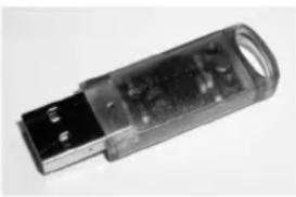
Many Steinberg products, including HALion, use the USB-eLicenser, a hardware copy protection device. HALion will not run without an eLicenser containing an activated license.

The USB-eLicenser is a separate product and is not included in the product package of HALion.
natural_image
Close-up of a transparent cylindrical electronic device with a small metallic connector (no visible text or symbols)The USB-eLicenser
The USB-eLicenser is a USB device on which your Steinberg software licenses are stored. All hardware-protected Steinberg products use the same type of device, and you can store more than one license on one device. Also, licenses can (within certain limits) be transferred between USB-eLicensers. This is helpful if you want to sell a piece of software, for example.
The product package of HALion contains an activation code, which is found on the Essential Product License Information card within the product package. To make unlimited use of your version of HALion, you must manually download a license to an USB-eLicenser connected to your computer, and activate your permanent license using the activation code.
In the eLicenser Control Center you can activate new licenses and check which licenses are installed on your USB-eLicenser. After installation of HALion, the eLicenser Control Center can be opened via the Start menu on Windows systems or the Applications folder on a Mac.
If you are using other copy-protected Steinberg products, you may want to transfer all licenses for your applications to one USB-eLicenser, thus using up only one USB port of your computer. Please refer to the eLicenser Control Center Help for information on how to transfer licenses between USB-eLicensers.
System Requirements
To use HALion, your computer must meet the following requirements:
Windows
- Windows Vista or Windows 7
- Pentium/Athlon 2.0 GHz dual core CPU
- 2 GB RAM
- Approx. 15 GB of free hard disk space
- Display resolution 1280 x 800 pixels recommended
- DirectX compatible audio hardware (ASIO compatible audio hardware recommended for low-latency performance)
- DVD-ROM drive with dual-layer support
- USB port for USB-eLicenser (license management)
- USB-eLicenser (not included)
- Internet connection for license activation
- For using HALion as a plug-in, a VST2 or VST3 compatible host is required.
Macintosh
- Mac OS X 10.6
- Intel Core Duo 2.0 GHz processor
· 2 G B R A M - Approx. 15 GB of free hard disk space
- Display resolution 1280 x 800 pixels recommended
- CoreAudio compatible audio hardware
- DVD-ROM drive with dual-layer support
- USB port for USB-eLicenser (license management)
- USB-eLicenser (not included)
- Internet connection for license activation
- For using HALion as a plug-in, a VST3 or AU compatible host is required.
Installing HALion
HALion provides a large amount of content and is distributed on a set of two DVDs. Please have all DVDs ready for the installation.

The HALion installer allows you to save the content files on a different hard drive than the program files.
Proceed as follows:
- Insert the first DVD into your DVD drive.
An interactive Start Center appears. If it is does not open automatically or if you have a Macintosh computer, you can manually open it by double-clicking the file "HALion_Start_Center.exe" (Windows) or "HALion Start Center.app" (Mac).
- Follow the instructions on screen to start the installation of HALion and browse through the additional options and information presented.
If you do not want to install HALion via the interactive Start Center, follow the instructions below:
Windows
- Double-click the file called "Setup.exe".
- Follow the instructions on screen.
Macintosh
- Double-click the file called "HALion.mpkg".
- Follow the instructions on screen.
Register Your Software!
We encourage you to register your software! By doing so you are entitled to technical support and kept aware of updates and other news regarding HALion.
- To register HALion, click the Steinberg logo in the top right corner of the control panel and select "Register HALion now!" from the pop-up menu.
This option opens the registration page of the Steinberg web site in your web browser. To register, follow the instructions on screen.
Setting Up
The following sections describe how to use HALion as a plug-in in different host applications. HALion can also be used as a standalone application. This is described in detail in the chapter "Using the HALion Standalone Version" on page 159.
Setting Up HALion as a VST Instrument in Cubase
We assume that you have correctly set up Cubase as well as your MIDI and audio hardware, and that Cubase receives MIDI data from your external MIDI keyboard. If you want to use HALion in another VST host application, please refer to the documentation of the corresponding application.
Cubase provides two ways of working with VST instruments: the VST Instruments window and instrument tracks.
Accessing HALion via the VST Instruments Window
Proceed as follows:
- Open the Devices menu in Cubase and select the VST Instruments option.
The VST Instruments window opens.
- Click one of the empty slots to open the instrument pop-up menu, and select HALion.
You are asked whether you want to create an associated MIDI track connected to the VST instrument.
- Click Create.
HALion is loaded and activated, and its control panel opens. A MIDI track called HALion is added to the track list. The output of this track is routed to HALion.
Accessing HALion via an Instrument Track
Proceed as follows:
- On the Project menu, open the Add Track submenu, and select "Instrument".
The Add Instrument Track dialog opens. - On the instrument pop-up menu, select HALion.
- Click OK to create the instrument track.
- Click the Edit Instrument button in the Cubase Inspector to open the HALion control panel.
HALion is now set up as a VST instrument in Cubase. For more details about the handling of VST instruments, see the Cubase Operation Manual.
Selecting Outputs
HALion loads with a stereo output configuration by default. However, you can use up to 32 stereo outputs plus one 5.1 output in Cubase. This allows you to route all 64 program slots to a dedicated Cubase Mixer channel.
To make these outputs available, proceed as follows:
- Open the VST Instruments window.
- Click the output button for the HALion instrument.
- Activate the required outputs.
Cubase automatically creates a MIDI track for each additional output and adds a channel to its Mixer. You can now route HALion programs or layers to these outputs for further signal processing within Cubase.
Using HALion in an AU Compatible Application
You can use HALion in an AU host application (e.g. Logic). The AU version of HALion is installed in your AU plug-ins folder and lets HALion work in an AU environment without any performance loss or incompatibilities.
For Logic Pro, proceed as follows:
- Open the Track Mixer and select the instrument channel that you want to use.
- Click in the I/O field, and select the AU Instruments submenu.
- On the Steinberg submenu, select HALion.
- Select Multi Output or Stereo from the submenu. HALion is now loaded as an AU instrument.
2
The HALion Control Panel
Introduction
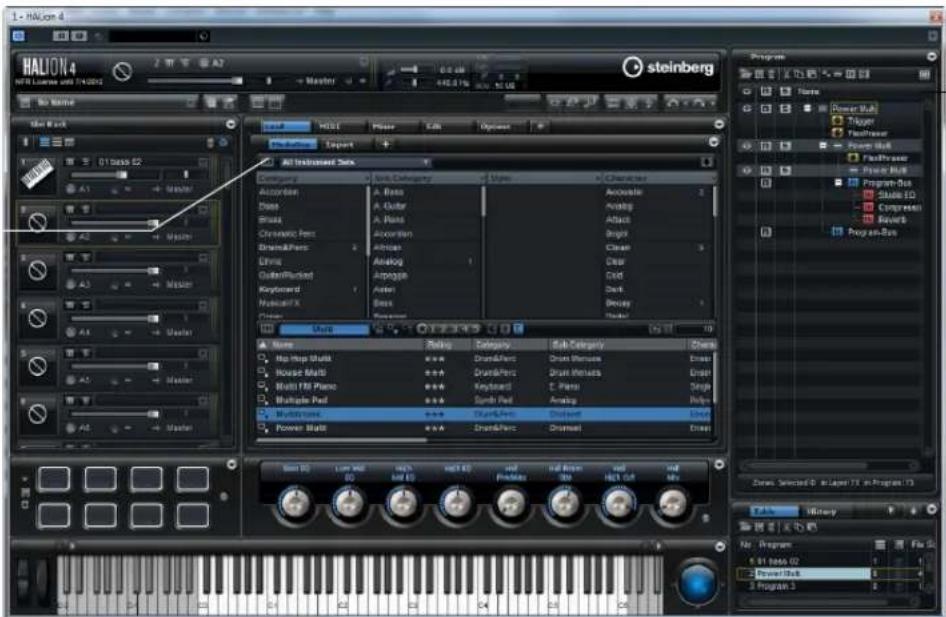
HALion provides flexible and highly customizable window management. You can arrange the available editors in the window, structure the window sections using tabs, and even configure several separate windows for your work. The size of each window, and window section, is freely adjustable. This allows you to make the most of the available screen space.
A view with multiple editors on different tabs.
A view with a single editor.
Configuring the Control Panel
You can set up the control panel exactly the way you want it, by determining the number of different sections (which are referred to as "views" in this document) that you want the window to contain, and by further configuring these sections, for example by adding tabs. For each of these elements (views or tabs), you can specify the editor that is displayed.
All these functions can be performed via the setup options. For views, these can be accessed via the View popup menu. For tabs, they are available on the context menu.
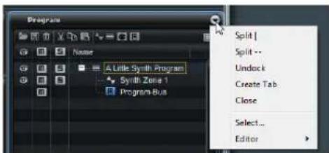
The following setup options are available:
Select... (Editor)
To select the editor to be displayed, open the Editor sub-menu, and select the editor or choose "Select..." to display a pane showing icons for the available editors and click on an icon.
"Split |" and "Split --"
You can add a view or tab to the window by splitting an existing view or tab.
- To perform a vertical split, select "Split |". This adds a new editor to the right of the current editor.
- To perform a horizontal split, select "Split --". This adds an editor below the current editor.
- You can also create a split view or tab by clicking its upper left corner and dragging it to another position in the window.
This creates a copy of the view or tab at the drop position. A colored frame indicates where it will be inserted when you drop it.
Adjusting the Size of a Split View
- To adjust the size of two split views, point the mouse at the divider between these two, click, and drag. If a view is split into three or more parts, these parts are resized proportionally. To resize an individual part, hold down [Ctrl]/[Command] and drag.
⇒ Some editors have fixed default sizes for height or width. For example, the Slot Rack can only be resized vertically but not horizontally.
Create Tab
- Select "Create Tab" to create a tab. You can also create tabs within tabs.
You can also create tabs the following way:
- Click in the upper left corner of an existing view or tab and drag it onto another one.
- Click the plus icon to the right of the rightmost tab and click the icon for the editor you want to display.
If a view contains more tabs than can be displayed, arrow buttons are displayed to navigate between the tabs.
Renaming Tabs
When you create a tab, it gets the name of the editor it displays. You can rename tabs via the context menu.
Close
- To remove a view or a tab, select Close.
Undock
- To create a duplicate of the view or tab in a new window, select Undock.
Further Setup Options
Moving Views and Tabs
- To move a view or tab, hold down [Shift], click in its upper left corner, and drag it to another position. Depending on the drop position, it is added as a tab or as part of a split view.
Expanding and Resizing Editor Sections
Some editors, such as the Options editor, contain expandable sections. These sections can be resized or collapsed so that they only show their title bar. This helps you save space and focus on the edited parameters.
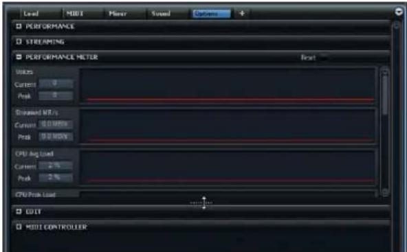
- To expand or collapse a section, click the "+" or "-" icon on the left of the title bar, or click the title bar.
- To open several sections at the same time, hold down [Ctrl]/[Command] and click the "+" icon or the title bar.
- To resize a section, click in the middle of its lower border (the position is indicated by a dotted line) and drag up or down.
Setting the Focus
It is useful to know which view, window, or tab has the focus, because this is where your key commands are applied, for example. The view that has the focus is indicated by a blue frame.
- To set the focus on a specific view, use one of its controls or edit a parameter.
You can also click on the frame of a view or in an empty background of a section.
Working with Multiple Windows
Creating Additional Windows
You can create new windows from existing views using the following methods:
- Click in the upper left corner of an existing view or tab and drag it out of the current window.
- Use the Undock command, see "Undock" on page 14.
The window menu bar contains a pop-up menu from which you can select the program that you want to edit.
Using Window Presets
HALion comes with several preconfigured window presets. You can open these by clicking the "Open New Window" button in the top bar and selecting a preset from the pop-up menu. You can also create your own window presets using the corresponding commands on the pop-up menu.
Locking Windows
When you open an additional window, HALion shows the settings belonging to the focused object (program, layer, zone etc.). This way, all editors and separate windows relate to the same material.
However, in some cases it might be necessary to show different objects in different windows, for example, to compare the parameter sets of two zones or layers. This can be achieved by locking a window.
- To lock a window, click the lock button in the upper right corner. If this is activated, the window no longer follows selection and focus changes in the main plug-in window. Instead, it displays the settings of the program that was selected when you clicked the lock button.
Screen Sets
When you have set up the HALion control panel to your liking, you can save this configuration as a "screen set". This way, you can preconfigure HALion for different workflows and editing situations.
When you start HALion for the first time, the default screen set is used, which is optimized for wide-screen monitors and contains all editors.
The following factory screen sets are available:
Screen Set Recommended Resolution
Description
Default 1440 x 900 Full editor screen set.
Basic 1024x768 A minimized single slot player view.
Extended1 1280x800 Optimized for laptops.
Extended2 1440 x 900 As Extended 1, but slightly more complex.
Advanced 1440 x 900 Full editor screen set.
Managing Screen Sets
You can load, save, and delete screen sets by clicking the screen set button on the toolbar in the plug-in functions section and selecting the corresponding command from the pop-up menu.
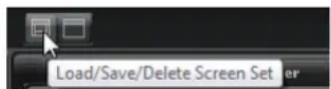
⇒ Factory screen sets cannot be deleted.
Overview of the Available Editors
HALion provides a large amount of different editors that give you access to the parameters of the plug-in and its programs and modules.
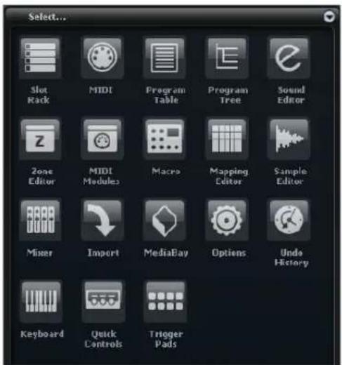
The following editors are available:
Slot Rack
Allows you to load and manage the loaded programs, see "The Slot Rack" on page 19.
MIDI
Allows you to configure the ranges and MIDI parameters of the slots, see "The MIDI Editor" on page 113.
Program Table
Shows all programs that are loaded. This includes the programs that are used in the Slot Rack as well as those that can be loaded via MIDI program change, see "Loading and Managing Programs" on page 27.
Program Tree
Allows you to create programs by combining samples, layers, busses, as well as MIDI and audio effects, see "Using the Program Tree" on page 30.
Sound Editor
Gives you access to the parameters of the various program components. It can display the parameters of programs, layers, zones, MIDI modules, busses, and effects. Which parameters are displayed depends on the object that is selected in the Program Tree.
Zone Editor
The Zone editor allows you to edit the parameters of all zones of the focused layer simultaneously (including any sublayers).
In case any specific zones are selected in the Program Tree or Mapping editor, only these zones can be modified.
MIDI Modules Editor
The MIDI Modules editor allows you to edit the parameters of all MIDI modules of the currently focused layer.
In case any specific MIDI modules are selected in the Program Tree or Mapping editor, only these modules are displayed and available for modification.
Optionally, you can show any MIDI modules found higher up in the signal flow by clicking the corresponding button.
Macro
This is a content-specific editor that provides a set of the most important program parameters. Whether such an editor is available for a program, depends on the content set, see "Macro Pages" on page 17.
Mapping Editor
Allows you to specify and visualize how samples are distributed over the keyboard and velocity range, see "The Mapping Editor" on page 98.
Sample Editor
Allows you to define all sample and loop parameters, see "Editing Samples in the Sample Editor" on page 103.
Mixer
Allows you to mix the program slots, access the output and AUX busses, and manage effects, see "Mixing and Routing" on page 116.
Import
Allows you to import external sampler formats like Apple EXS, GigaSampler, Kontakt, and others, see “Importing and Exporting Samples” on page 55.
MediaBay
Allows you to load programs and layers, see "Managing Files via the MediaBay" on page 22.
Options
Contains global plug-in settings regarding the overall performance, global edit functions, and MIDI controllers, see "The Options Editor" on page 42.
Undo History
The Undo History lists all of your actions and allows you to undo changes, see "Undo/Redo" on page 41.
Keyboard
Combines a keyboard, two wheels, and the HALion Sphere. You can use these controls to simulate external hardware, see "The Keyboard Editor" on page 41.
Quick Controls
Allows you to remote-control any parameter inside the program, see "Quick Controls" on page 45.
Trigger Pads
Allow you to assign and trigger notes and chords. Furthermore it is possible to use the trigger pads to switch the states of FlexPhraser modules, see "The Trigger Pads" on page 144.
Macro Pages
VST Sound Instrument Sets provide dedicated editors, so-called Macro pages. These Macro pages are preconfigured to show the most important parameters for the specific programs.
Whether it is possible to edit a program only via its Macro page or whether you have access to all underlying zone and layer parameters depends on the instrument set.
If a program comes with a Macro page, it is displayed when you open the Macro editor.
When loading a program that contains one or multiple layers with Macro pages, all Macro pages are shown together in the Macro editor. For each existing Macro page, HALion inserts a navigation button on the toolbar that allows you to switch between the different Macro pages.
Managing Your Sounds
The Slot Rack
Slot Sizes Program Loader Remove All Programs
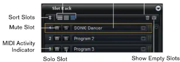
The Slot Rack allows you to load up to 64 programs into so-called slots. Slots are created dynamically for each loaded program. Their order can be arranged freely, sorted by MIDI channel, or slot index.
Use the scrollbar to the right of the slots to navigate to the slot that you want to make settings for.
Changing the Slot Size
You can change the size of the slots that are displayed using the sizing buttons above the slots. The following options are available:
Size Features
Small Shows MIDI Indicator, Mute, Solo, Program Loader
Medium Shows MIDI Indicator, Mute, Solo, Program Loader, MIDI Port/Channel, Level, Pan, Level Meter
Large Shows Instrument Icon, Mute, Solo, Program Loader, MIDI Indicator, MIDI Port/Channel, Polyphony, Level, Pan, Output, Level Meter
Showing Empty Slots
By default the Slot Rack only shows slots that are currently filled with programs.
- To show all empty slots, activate the "Show Empty Slots" option on the toolbar.
Loading Programs
Programs and layers can be dragged from the following locations into the Slot Rack:
- HALion or Cubase MediaBay
■ Program Table or Program Tree - Import View
- Explorer (Win) or Finder (Mac)
Replacing Programs
You can replace the program in a slot by dragging another program or layer onto this slot.
Alternatively you can use the "Load Program" button at the right of the slot to load a new program.
Loading Programs in between Slots
- If you want to add a program or layer in a new slot between two existing slots, you can drag it between these slots.
A red line indicates that a slot will be inserted at this position.
⇒ The slot number is taken from the first available slot and does not necessarily reflect the order in which the slots are listed.
Loading Layers into Slots
If you load a layer into a slot, HALion creates a new program.
Managing Programs via the Slot Context Menu
The slot context menu provides additional functions for managing programs. The following options are available:
Option Description
| Load Programs | This option opens the “Load Program” dialog. Select a program or layer and click OK to load it into the slot. |
| Save Program | This option saves the program. Please note that factory content cannot be overwritten. Instead, the “Save Program” dialog is opened and you can save the edited program under a new name. |
| Save Program As... | This option opens the “Save Program” dialog where you can save the edited program under a new name. |
| Remove Program | Select this option to remove the program from the slot. |
| Revert to Last Saved Program | Select this option to discard any changes made to the program in the slot. |
| Cut Program | Select this option to copy and remove the program from the slot. |
| Copy Program | Select this option to copy the program without removing it. |
| Paste Program | Select this option to paste the copied program into the slot. If the slot already contains a program, it is replaced. |
| Rename Program | Select this option to enter a new name. |
Option Description
Reset Selected Slot
Select this option to reset the selected slot to the default values.
Reset All Slots Select this option to reset all slots to the default values.
Loading Samples and Third-Party Programs
Samples and third-party programs can be loaded into the Slot Rack from a file browser or the Import editor using drag and drop.
Renaming Programs
You can rename a program via the context menu.
To make the program with its new name available in the MediaBay, you must save it.
Sorting Modes
By default, slots are arranged freely. New slots are set to the next available index number.
- To change the sorting mode, click the Sort Slots button on the left side of the Slot Rack toolbar, and choose a mode:
Mode Description
Custom Sorting Default mode.
Sort Slots by MIDI Port and Channel
Slots are sorted by their MIDI channels. No reordering is possible. New slots are set to MIDI channel A1.
Sort Slots by Index Slots are sorted by their index-number. No reordering is possible. New slots are set to the next available index-number.
Slot Controls
Depending on the selected slot display size you get access to additional slot controls.
Level
The level fader controls the output level of a program. The parameter has an influence on all outputs used by layers and zones inside the program.
Pan
Pan controls the stereo position of a program. The parameter has an influence on all outputs used by layers and zones inside the program.
⇒ The Pan control is disabled if the slot bus has a surround configuration.
Solo
Activate the Solo button of a slot in order to hear only the corresponding program. Several slots can be soloed at the same time.
Mute
Activate the Mute button to turn off playback of the program.
MIDI Port and Channel
Here you can specify on which MIDI port and channel the slot receives MIDI messages.
MIDI Activity Indicator
A green bar next to the slot number and symbol indicates incoming MIDI data.
Polyphony
Here, you can specify how many notes can be triggered simultaneously.
⇒ The number of resulting voices can be much higher if one note triggers several zones at the same time.
Output
The output selector lets you define to which output bus the slot sends its signal.
⇒ This setting does not affect any output routing that has been set up for individual layers or zones inside the program.
Level Meter
The level meter indicates the signal level of the slot output bus.
→ Layers and zones inside the program that are routed to individual outputs do not show any meter activity.
The Relationship between Slot and Program Table
The Program Table provides a list of all programs that are loaded into slots as well as programs that are not yet loaded but can be addressed by a program change.
When a program is loaded into a slot, it is also inserted in a free place in the Program Table.
When replacing a program in a slot, the table updates accordingly. If multiple slots have used the same program, all slots are updated with the new program.
Managing Multis
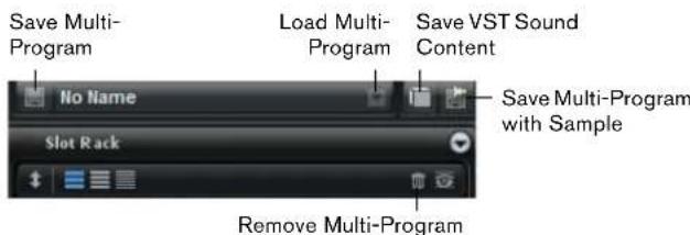
Multis can load multiple sounds or programs and combine them. You can use multis, for example, to layer several programs or to create split sounds by setting several programs to the same MIDI input channel. However, the most common usage is to create sound sets with different instruments set to individual MIDI channels.
A multi-program contains all plug-in parameters. When using HALion as a plug-in in Cubase or Nuendo, these multis are listed in the Preset Management pop-up menu of the host application. You can drag multis and programs from the Cubase or Nuendo MediaBay to a slot in HALion.
When using HALion as a plug-in in a different host application, you can use either the preset functionality from the host application, or the multi management features provided by HALion.
Loading Multis
- Open the MediaBay and double-click a multi, or drag and drop a multi onto the multi slot.
- Alternatively, click the "Load Multi-Program" button in the multi slot to open the "Load Multi-Program" dialog, select a multi and click on OK.
Removing Multis
- To remove all programs of the current multi, click the "Remove All Programs" button on the toolbar of the Slot Rack.
This also resets all slot parameters and removes effects from the slot busses. However, AUX and Master effects are not removed.
→ Removing the programs from the slots does not remove them from the Program Table.
Saving Multis
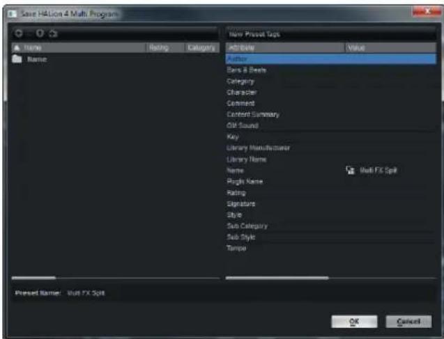
To save multis, proceed as follows:
-
Click the "Save Multi-Program" button.
-
Enter the name of the multi.
-
Assign any attributes you require and click OK. If the entered name already exists, the "Make Unique Name" option adds a number suffix to the name of the new multi.
Creating Subfolders for User-Defined Multis
You can create subfolders inside the user preset folder to organize presets.
- To create a new folder, click the "Create New Folder" icon at the top left of the "Save Multi-Program" dialog.
Navigating Through the Folder Hierarchy
You can move through the folder hierarchy using the three navigation buttons at the top left of the dialog.
They allow you to navigate to the previous or next browse location, or browse the containing folder.
Editing Attributes
In the "New Preset Tags" section on the right of the "Save Multi-Program" dialog you can edit the attribute values that are assigned to the preset.
- To edit an attribute, click on a value field, and enter the new name or value.
- Click OK to save the preset.
For further information about attributes, see "Editing Preset Attributes" on page 24.
Exporting Multis with Samples
Multis with samples can be exported, to transfer a complete multi to another computer. Programs that use samples from VST Sound containers cannot be exported.
To export a multi with samples, proceed as follows:
- Click the "Export Multi as VST3 Preset with Samples" button next to the multi slot.
- Enter the name of the multi, and click OK.
The multi is written to the specified location. Additionally a folder named after the preset that contains all samples is created.
Exporting VST Sound Files
You can produce your own HALion VST Sound files, containing all plug-in settings, programs, and samples.
- Click the "Export Multi as VST Sound" button next to the multi slot.
- Enter the required information (marked with an asterisk) and provide additional data (optional).
- Enter the path or click the browse button to specify a file name and folder.
- Click OK.
⇒ You cannot include samples that originate from protected VST Sound files.
Managing Files via the MediaBay
The MediaBay gives access to the HALion presets, such as multis, programs, and layers.
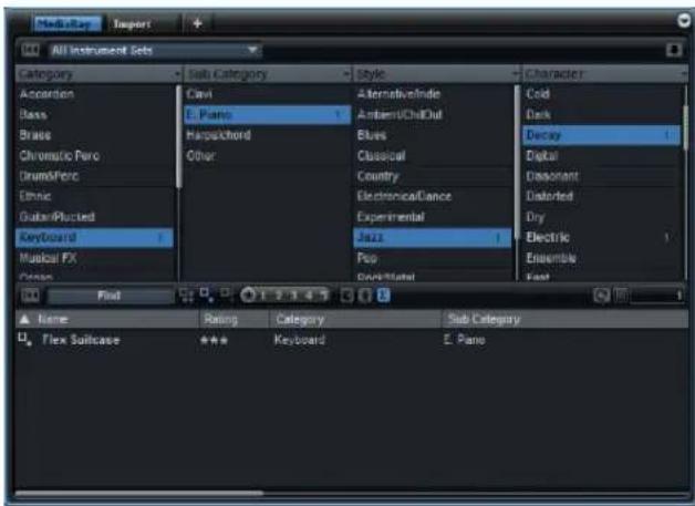
The MediaBay is divided into two sections. In the top section you can define which kind of sounds you want to look for. The lower section presents the corresponding results list. You can drag the divider at the top of the results list to adjust the size of the two sections.
Loading Programs into Slots
To load a program into one of the slots of the Slot Rack, you have the following possibilities:
- Select the slot into which you want to load the program and double-click the program in the results list.
- Drag a program from the results list to an empty space in the Slot Rack to create a new slot. If you drag it to an existing slot, the current program is replaced.
- Right-click the program and select "Load Program into selected Slot" from the context menu.
Importing Presets
You can import existing program presets from any file location using the Explorer (Win) or Finder (Mac). To import presets, proceed as follows:
- Select the preset in the Explorer/Finder.
- Drag it to the MediaBay.
The imported presets are copied to your user folder.
Deleting Presets
- To delete a user preset, right-click it to open the context menu, and select Delete.
→ Factory presets cannot be deleted.
Applying Filters
Category Filter
You can filter the results list based on up to four filter criteria using the configurable attribute columns.
Standard attributes are Category, Sub Category, Style, and Character. By clicking on specific values in the columns, you define the filter. Only the files that match the selected values are displayed in the results list. Select more values from other columns to refine the filter.
- To select different filter criteria, click the column header, and select a different attribute from the submenu.
Instrument Set Filter
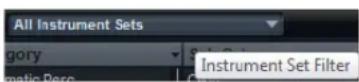
Use the "Instrument Set Filter" pop-up menu to search a certain content set only. By default, the search is performed in any of the installed content sets.
Using the Results List
The results list shows all files that have been found according to the category filter.
View Filters
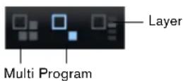
The toolbar of the results list has three filter buttons to define which preset types are displayed. Presets can be multis, programs, and layers. To show a preset, activate the corresponding icon. In the results list, the corresponding icon is shown to the left of the preset name.
Columns
The columns of the results list show all the attribute values for the presets that match the filters that you set up in the top section.
You can reorder the columns in the results list by dragging the table headers to another position. Furthermore, you can use the column headers to change the sorting of the list entries. The triangle in the column header shows the sorting direction.
Setting Up the Result Columns

You can select which attribute columns are displayed, by clicking the "Set up Result Columns" button on the toolbar of the results list. The attributes that you choose are added at the right of the list.
Rating Filter
You can limit the results list to presets that have a certain rating. The rating slider allows you to define the minimum rating.
Text Search

In the text search field on the results list toolbar you can enter text contained in the name or any of the attributes of a preset that you are looking for. The results list updates immediately and the Category search section above shows all categories that contain presets matching the text search.
Resetting the Result Filter

- To reset the text-based result filter, click the Reset button to the left of the search field.
Content Filter
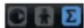
The content filter buttons allow you to define whether you want to see all presets, only the factory presets, or only your user presets.
The Results Counter
The number of presets that match the filter criteria is displayed at the far right of the results list toolbar.
Using the Context Menu of the Results List
The context menu of the results list offers additional options for managing the selected presets. The following options are available for factory and user presets:
Options Description
| Load Program into selected Slots/ Load Multi-Program | This loads the highlighted preset. |
Select All This selects all presets in the results list.
Select None This cancels any selection.
The following options are available for user presets only:
Options Description
| Copy This copies the selected presets to the clipboard.This way, you can paste them at a different location using the file browser of your OS. | |
| Rename This opens a dialog for renaming the highlighted preset. | |
| Delete This moves the selected presets to the trash bin of your operating system. | |
| Show in Explorer/Reveal in Finder | This shows the preset in the file browser of your operating system. |
| Set or remove Write Protection | This sets or removes the write protection for the selected presets. |

Programs from the HALion factory content are write-protected and cannot be deleted or renamed.
Editing Preset Attributes
Each preset can be described using a predefined set of attributes. These attributes can be set directly in the results list or in the section "New Preset Attributes" of the Save dialog.
-
Click in the field of the attribute value that you want to set.
Depending on the attribute, a menu or a dialog opens. -
Select a value.
Attribute values are written directly into the corresponding preset files. However, this is not possible for write protected factory content. In this case, the data is saved within HALion's MediaBay database.
Attributes
Attribute values can be set directly in the results list or the Save dialog. The following table shows how to edit the various attribute values:
| Attribute type | Attribute Editing method | |
| Media | ||
| Name Display only. | ||
| Rating Drag to set the rating. | ||
| Comment Click to select, double-click to edit. | ||
| Content Summary Click to select, double-click to edit. | ||
| Write Protection Display only, use context menu to set protection. | ||
| Library Name Click to select, double-click to edit. | ||
| Library Manufacturer | Click to select, double-click to edit. | |
| Author | Click to select, double-click to edit. | |
| Musical | ||
| Category | Click to select. | |
| Sub Category | Click to select. | |
| Style | Click to select. | |
| Sub Style Click to select. | ||
| Character Click to open an editor dialog. | ||
| Tempo | Click to select, double-click to edit. | |
Bars & Beats Click to select, double-click to edit.
Signature Click to select, double-click to edit.
Key Click to select.
GM Sound Click to select.
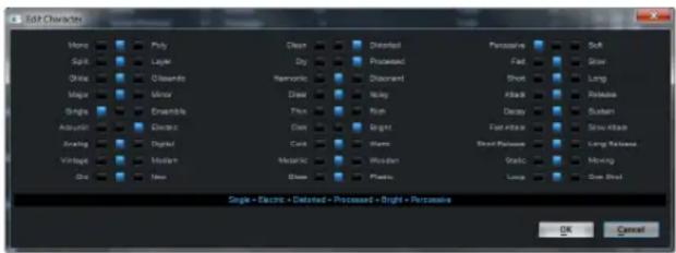
Setting the Character Values
Character attribute values can be set via a dedicated editor. This editor provides a list of values that describe the character of a sound.
Content Files and Folder Structure
HALion has a large amount of ready-to-use sound content, made up of hundreds of multis, programs, and layers. This content is write-protected. You can edit files while they are loaded in HALion, but you cannot overwrite the factory content files themselves.
To save edits to the factory content, save the files under a new name. These files have the name extension ".vstpreset" and are referred to as "user content". They can be searched and categorized in the same way as factory content.
User content is saved in a predefined folder structure on your hard disk. You can create subfolders within this structure, to facilitate moving or exchanging content (see "Creating Subfolders for User-Defined Multis" on page 21).
Loading HALion 3 Programs
HALion 4 allows to load HALion 3 presets either from HSB container files or from FXP/FXB files. To be able to load presets from HALion 3 HSB files, they have to be registered in the HALion 4 MediaBay.
Registering HSB Files
- Click the Import button on the right of the Category Filter toolbar, and select "Register HSB/VST Sound Files".
- Navigate to the HSB/VST files, select them, and click OK.
The MediaBay now has access to the presets.
- Alternatively, HSB/VST files can be registered by dragging them from the Windows Explorer or Mac OS Finder into the HALion MediaBay.
Registering VST Sound Files
Programs that are contained in VST Sound files can only be seen and accessed by the MediaBay if the corresponding VST Sound file has been registered. HALion's factory content is located in a directory that is automatically scanned when HALion is loaded. However, it is possible to add further VST Sound files that are not located in that directory.
To register a VST Sound File, proceed as follows:
- Click the Import button on the right of the Category filter toolbar.
- Select "Register HSB/VST Sound Files".
- Navigate to the VST Sound file, select it, and click OK. The MediaBay now has access to the presets.
Loading FXP/FXB Files
To load FXP/FXB files there are two possibilities:
- Drag and drop the FXP/FXB files from the Windows Explorer or the Mac OS Finder onto the Slot Rack.
- Drag and drop the FXP/FXB files to the Slot Rack/Multi Loader.
HALion converts the FXP/FXB files into HALion programs/multi-programs.
Importing FXP/FXB Files
To import multiple FXP/FXB files without loading them in HALion, proceed as follows:
- Click the Import button to the right of the Category Filter and select "Import HALion FXP/FXB Files".
- Navigate to the folder that contains the FXP/FXB file.
- Select the file you want to import and click OK.
The presets are converted into the HALion 4 format and saved as VST presets in the user preset folder.
Alternatively, import multiple FXP/FXB files by dragging them from the Windows Explorer or Mac OS Finder into the MediaBay.
Working with General MIDI Files
HALion can play back files in the General MIDI format. For this, the following preparations must be made:
- Load a GM multi from the MediaBay.
The first 16 slots are prepared with send effects for Chorus and Reverb. - Open the Options editor, navigate to MIDI Controller, and activate "Receive Program Changes" and "Receive RPNs 0/1/2".
- Load the GM file that you want to use.
HALion loads the necessary programs and adjusts chorus and reverb levels.
4
Loading and Managing Programs
Introduction
HALion allows you to load a virtually unlimited number of programs per instance. All loaded programs, i. e. programs that can be used in the current project, are shown in the Program Table. You can load these programs into any of the 64 slots in the Slot Rack.
The first 128 entries of the Program Table correspond to the 128 MIDI program change numbers. You can load these programs into a slot by sending MIDI program change messages on the slot's MIDI channel.
⇒ You can set the focus on any of the programs, for example to verify settings or to copy zones from there, without having it assigned to any slot. In that case you cannot play and hear the program.
The Columns of the Program Table
The Program Table contains the following columns:
Column Description
| Program Number Displays the program number, which corresponds to the MIDI program change number. |
| Program Name Shows the program name. The name can be edited in place. |
| Used Displays the number of slots in which the program is loaded. |
| Preload Shows if a program is preloaded, even if it is not being used in a slot. |
| File Size | Displays the size of the program with all samples as it is stored on the hard disk. |
Configuring Columns
Inserting Columns
- Right-click the column header at the position where you want to insert the new column, and select the parameter or column that you want to insert.
Removing Columns
- Right-click the header of the column you want to remove, and select "Remove...".
Reordering Columns
- Drag and drop the header of the column left or right to the new position.
Changing the Width of a Column
- Drag the right border of the column header left or right to change its width.
→ All modifications are stored with the project.
Loading Programs into the Program Table
There are several ways to load a program into the Program Table:
- Drag it from the MediaBay to the Program Table.
- In the MediaBay, right-click a program to open the context menu, and select "Load Program into selected Slot".
- Click the "Load Program" button in the Program Table toolbar, select a program, and click OK.
If the selected entry in the Program Table already contains a program, the current program is replaced. All slots that are making use of that program then refer to the new program.
When multiple programs are dropped on a list entry, not only the target program is replaced but also the following programs. The number of programs that are replaced corresponds to the number of programs that you have dragged to the Program Table.
⇒ You can also drag and drop programs from third-party sampler formats using the Import Tree, see “Importing Third-Party Sampler Programs” on page 62.
Loading Programs from the Program Table to the Slot Rack
When dropping a program onto a free Program Table entry, it is added to the table without being actually loaded to any of the slots. This way you can create a program table without having to load all programs immediately.
If you want to use the program in a slot, you can create a new slot or replace the program in an existing slot.
In case a program is loaded multiple times to different slots the slot rack focus jumps to the first slot.
Creating New Slots
- Make sure that no slot is selected and double-click the program.
- Drag a program to an empty space in the Slot Rack.
Replacing Programs in Slots
- Double-click a program to replace the program in the selected slot.
- Drag a program from the table into an existing slot.
To quickly see which programs are assigned to slots their program numbers are displayed in yellow.
Preloading Programs
When a program was loaded to the Program Table but is not used by one of the slots, its samples are not pre-loaded. However, you can preload unassigned programs to allow for a faster MIDI program change. You can activate the Preload option individually for each program. This setting is saved with the project and plug-in preset. Proceed as follows:
- Open the context menu for a program and select "Always Preload".
- Activate the Preload icon of the program in the Preload column.
- To deactivate preloading, select "Preload Program On Demand" on the context menu, or deactivate the icon in the Preload column.
Editing the Program Table
Deleting Programs
You can delete the selected program by clicking the trash icon on the toolbar. Alternatively, you can press the [Delete]-key on your computer keyboard or use the Delete command on the context menu.
Exchanging the List Positions of Two Programs
Once a program has been loaded to a specific table entry, it is also associated with the corresponding MIDI program change number.
For example, loading a program at position 3 of the list means that this program can be loaded into a slot when it receives MIDI program change number 3 on its MIDI channel.
If you want to quickly assign the program to another MIDI program change number, you can drag it to the corresponding list position. In case another program already occupies this position, the two programs change places.
Cut, Copy, and Paste
Cut, copy, and paste programs by clicking the corresponding icons on the Program Table toolbar, using the commands on the context menu, or using key commands.
Renaming Programs
- Select the program you want to rename and click the program name a second time, or press [F2] (Win)/[Return] (Mac).
- Right-click the program and select Rename on the context menu.
Using the Program Tree
Introduction
The main area for navigating and making selections in HALion is the Program Tree. It shows the selected program with all its layers, zones, and modules. Furthermore, it allows you to load programs and layers, to add, import, or delete zones, etc.
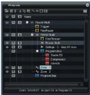
The first three columns in the Program Tree give you access to the Visibility, Mute, and Solo functions inside the program. In the section to the right, the selected program and its elements are displayed. They are organized in a hierarchical structure, with the program at the topmost level.
Each element in the Program Tree is displayed with an icon in front of its name, indicating the type of the element.
Programs and Layers
Programs are the top-level elements in the Program Tree. Only one program is displayed at a time.
A HALion program is a complex instrument or sound that combines layers, sample zones, synth zones, busses, MIDI modules, and FX modules. Often, a program contains a single layer that already comes with all necessary components such as the synthesis part or insert effects. This is because a layer already is a complete sound structure on its own. Layers can be used to organize programs, for example by grouping a number of zones. This is useful if you want to apply the same settings to a number of zones in one go. The program adds the possibility of combining different layers to build up more complex sounds or to create combinations of sounds you want to load as a unit. A typical example is a bass/piano split sound or a piano/string layer sound.
Zones
A zone is the element on the lowest level in the tree structure. The zones are the elements creating the sounds in HALion.
You can choose between synth and sample zones. These zone types differ in their basic sound source. While a synth zone provides an oscillator section with three main oscillators, a sub oscillator, a noise generator, and a ring modulation stage, the sample zone loads a specific sample instead.
Busses
Busses allow you to set up the audio routing in HALion and add audio effects.
MIDI Modules
MIDI Modules can be added for programs and layers, see "Adding MIDI Modules" on page 36.
Audio Effects
Audio effects can be added for busses. For a detailed description of the available audio effects, see the chapter "Effects Reference" on page 122.
The Program Tree Structure
The Program Tree represents the signal flow inside the program from top to bottom:
The MIDI comes in at the top and goes down through the layers and MIDI modules. The processing order of the MIDI modules inside the program or layers is from top to bottom.
The audio is output via busses that can have any number of FX modules. The processing order of the FX modules inside the busses is also from top to bottom.
Number of Selected Zones
Below the Program Tree, there are three numbers that indicate the following:
- The first number indicates the number of selected zones.
- The second number indicates the number of zones contained in the focused layer.
- The third number indicates the total number of zones in the program.
The three numbers are particularly useful while editing or deleting zones. For example, if you have a piano that was recorded with several velocity layers per note, you will know that each velocity layer has 88 sample zones. Let's say, you want to edit or delete a whole velocity layer. With a look at the three numbers you will know if you selected the right amount of sample zones before you edit or delete them.
The Color Scheme
To indicate additional information, the icons of the program, layers, and zones change their color.
Icon Color Description
| Light blue | This is the standard color for zones. For sample zones this color means all samples were found and loaded without problems. |
| Red The icon turns red if a sample zone cannot find its sample, for example, because a removable hard drive is not connected. | |
| Yellow When you create a new sample zone, it is not linked to a sample, yet. To indicate this, the icons of the corresponding sample zones turn yellow. | |
| Magenta To free memory on your computer, you can remove the samples completely from RAM. The samples are played back from the hard disk only. To indicate this, the icons of the corresponding sample zones turn magenta. | |
| Dark blue To reduce hard-disk load, HALion can playback samples from RAM only. To indicate this, the icons of the corresponding sample zones turn dark blue. | |
Editing Zones, Programs, and Layers
Creating Zones
To create a new zone, you have the following possibilities:
- Drag and drop samples from the Cubase MediaBay, Windows Explorer, or Mac OS Finder to a program or layer.
- Right-click a layer in the Program Tree, open the New submenu, and select Zone.
- Click the Zone icon on the toolbar of the Program Tree.
When creating new zones, HALion uses the default zone preset to set the zone parameters to their default values. This preset contains all zone parameters, but no sample-related parameters (sample start/end, loop start/end, etc.).
To use specific zone settings, modify the default preset, and save it as default in your "user presets" directory.
Creating Layers
To create new layers you have the following possibilities:
- Click the "Create New Layer" icon on the toolbar. When a layer is selected, the new layer is added within this layer. When a zone is selected, the new layer is added on the same hierarchy level as the zone.
- Too add multiple layers on the same level, [Shift]-click the "Create New Layer" icon on the toolbar.
- Right-click a layer, open the New submenu, and select Layer.
Saving Programs and Layers
You can save programs and layers from the Program Tree as VST presets.
- To save a program, click the Save icon on the toolbar, or use the "Save Program" command on the Load/Save sub-menu of the context menu.
- To save a certain layer, open the context menu, select the "Load/Save" submenu, and select "Save Layer".
Deleting Programs, Layers, and Zones
- Select the program or any number of layers and zones, and click the trash icon on the toolbar, or press [Backspace], or open the context menu and select Delete.
⇒ Deleting zones does not delete any samples on your hard drive.
Renaming Entries
When you create a new element in the Program Tree, it automatically gets a generic name. You can change this name in the following ways:
- Select an entry, click it a second time, and enter the new name.
- Select an entry, press [F2] (Win) or [Return] (Mac), and enter the new name.
Drag and Drop
Select the program or any number of layers and zones and drag the selection to a layer to move the selection inside this layer.
Using Cut, Copy, and Paste
- To cut the selected elements, use the Cut icon on the toolbar, the Cut command on the context menu, or the key command [Ctrl]/[Command]-[X].
- To copy the selected elements, use the Copy icon on the toolbar, the Copy command on the context menu, or the key command [Ctrl]/[Command]-[C].
- To insert the copied data, use the Paste icon on the toolbar, the Paste command on the context menu, or the key command [Ctrl]/[Command]-[V].
→ You can also copy or move the selection from one program to another. Furthermore, it is possible to move a complete program into another one. In this case the moved program becomes a layer inside the target program.
Paste to New Layer
To paste zones to a new layer, open the context menu for a zone, layer or program (depending on where you want to insert the new layer), and select "Paste to new Layer".
Copying and Pasting Zone Settings
- Right-click the zone that contains the settings that you want to copy, and select "Copy Zone Settings" from the context menu.
- Right-click one of the selected zones, and select "Paste Zone Settings" from the context menu.
Transfer Settings to Mapping
Zones often have varying Fine Tune and Level settings, while other settings stay the same across all zones. To avoid varying Fine Tune and Level settings in the zones, you can transfer these settings to the Tune and Gain parameter of the mapping.
- Right-click the program or the layers and zones.
- Open the "Transfer Settings to Mapping" submenu and specify which settings to transfer: "Select All" to transfer Fine Tune and Level at the same time or select "Fine Tune" or "Level" to transfer them individually.
- The corresponding zone settings are transferred to the mapping and reset to their default afterwards.
Applying Layer Settings to Zones
In some cases it can be helpful to apply the layer settings to the zones they contain.
- Open the context menu in the Program Tree and select "Apply Layer Settings to Zones".
- Select which settings to apply. You can either apply all settings at once or one of the following settings individually: Key Range, Velocity Range, Fine Tune, and Level Pan. All layer offsets are now calculated into the correspondent zone settings and then reset to a neutral position.
Example:
A program contains layers that are limited to a specific key range. The contained zones, however, use the full key range. In this case, all these zones fill the whole key range in the mapping editor and it is impossible to see their real limitations. To solve this, use the "Apply Layer Settings to Zones – Key Range" option so that the zones inherit the limits of the layers. The layers themselves are reset to the complete key range. Now, you can see the key range in the mapping.
Making Selections
The selection you make in the Program Tree defines which part of the program can be edited in HALion. The editors automatically follow the selection and display the available parameters. The name of the selected entry is marked in blue. If several elements are selected, the one with the focus is available for editing. It is indicated by an orange frame around its name. Any editing you perform always applies to the selection.
Selecting Elements
- To select an element, click on it.
- Use [Shift] and [Ctrl]/[Command] to select a range of elements.
- To select all zones within the same layer, double-click one of its zones.
- To select all elements of a layer, double-click the layer.
- To select the entire content of a program, open the context menu, select the Selection submenu, and choose "Select All".
- To select all subentries of an element, open the context menu, select the Selection submenu, and choose "Select Tree".
Using the Selection Filter
The Selection Filter lets you select a group of elements by double-clicking on a program, layer, or zone. By default, a double-click selects all elements of the Program Tree.
The Selection Filter can be set to select only zones, layers, effects, MIDI modules, or busses. Different icons indicate which Selection Filter is active.
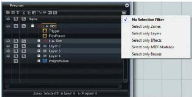
- To select a Selection Filter, click on the Selection Filter icon, and choose an option.
Expanding and Collapsing the Tree
- To show or hide the content of a layer, click the plus or minus sign in front of the icon.
- To expand or collapse an entire layer, including any sublayers, open the context menus for the layer, and select "Expand Tree" or "Collapse Tree".
Navigating in the Program Tree
When the Program Tree has the window focus, you can use the arrow keys for navigating in the Program Tree.
- When a single entry is selected, use the up and down arrow keys to select the previous or next entry, respectively.
- To open or close a selected layer, use the right or left arrow key, respectively.
- To expand the selection, use the up/down arrow keys while holding [Shift].
- With multiple entries selected, use the up and down arrow keys to set the focus to the previous or next selected entry.
If the Program Tree does not have the window focus, you can use the hotkeys [W], [A], [D], and [X] to navigate in it.
- To select the previous or next element in the Program Tree, press [W] or [D], respectively.
- To open or close the focused layer, press [D] or [A], respectively.
- If you are working with undocked views that have a Program Tree of their own, the hotkeys are applied to the view that has the window focus, provided the lock icon is activated.
Editing the Focused Entry
The Sound editor automatically shows the parameters of the focused entry, such as a zone or layer. By using the Sound editor together with the Program Tree you can easily access and edit all parts of the program.
Muting, Soloing, and Hiding
By muting, soloing, or hiding layers and zones, you can focus on editing certain parts of the program.
In addition, the Program Tree allows you to list a customizable set of zone parameters. This way, you can compare values between different zones directly in the Program Tree.
Muting Layers, Zones, and the Program
Layers and zones that are muted are not output when you hit a key. For muted zones or layers the Mute icon turns yellow. When a muted program or layer contains zones, these zones are muted as well. This is indicated by an orange Mute icon in front of the zones.
- To mute an element in the Program Tree, click the Mute icon in front of it. The corresponding icon turns yellow.
- To reset the muting settings, click the Mute icon on the toolbar.
- To mute the selected zones, open the context menu of the Program Tree, open the Mute/Solo submenu, and select "Mute Selected Zones".
- To mute all zones, open the context menu of the Program Tree, open the Mute/Solo submenu, and select "Mute All Zones". The program itself and any of its layers are not muted by this.
Soloing Layers, Zones, and the Program
When a layer or zone is soloed, only that layer or zone can be heard. For soloed zones or layers the Solo icon turns red. When a program or layer contains zones that are soloed, its icon turns pink.
- To solo an element in the Program Tree, click the Solo icon in front of it. The corresponding icon turns red.
- To reset the soloing settings, click the Solo icon on the toolbar.
- To solo the selected zones, open the context menu of the Program Tree, open the Mute/Solo submenu, and select "Solo Selected Zones". Alternatively, press [S] on your computer keyboard.
- To solo all zones, open the context menu of the Program Tree, open the Mute/Solo submenu, and select "Solo All Zones". The program itself and any of its layers are not soloed by this.
Making all Zones Audible Again
- On the context menu, open the Mute/Solo submenu, and select "Make All Zones Audible".
This resets all mute and solo states for the program. - Alternatively click the header of the Mute or Solo column to reset all mute or solo states.
Using "Solo Follows Selection"
The "Solo Follows Selection" function on the Mute/Solo submenu automatically solos the layers and zones you select. Other parts of the program are muted. This is useful if you want to switch between layers and zones and only have the current selection played back.
Using the Visibility Settings
Hidden layers and zones are not displayed in the Mapping editor.
Visible zones have an eye icon in the first column of the Program Tree. For invisible zones or layers the eye icon is dimmed. When a program or layer contains hidden zones, its icon changes to a half dimmed eye.
To hide or show layers and zones, you have the following possibilities:
- Click in the Visibility column for the layer or zone you want to hide or show.
- Use the options on the Visibility submenu of the context menu.
- To show a single layer or zone, [Alt]/[Option]-click its eye icon.
All other layers and zones are hidden.
- To show only the selected layers and zones, press [Ctrl]-[U] (Win) or [Alt]-[U] (Mac).
- To show all layers and zones, press [Shift]-[Ctrl]-[U] (Win) or [Shift]-[Alt]-[U] (Mac).
Using "Auto Visibility"
The “Auto Visibility” automatically shows the selected zones and any of their direct siblings that are part of the same layer. Other zones are hidden.
- To activate Auto Visibility, open the context menu, select the Visibility submenu, and choose Auto Visibility.
With this option active, you can still toggle the visibility of zones inside the visible layers.
Adding MIDI Modules
MIDI modules process the stream of MIDI events inside a program. They can produce monophonic modulation signals, which can be used as sources in the modulation matrix. The MIDI modules can be assigned to the whole program or a single layer.
To add a module, proceed as follows:
- With the program or a layer selected, click the "Create New MIDI Module" icon on the toolbar of the Program Tree.
- On the menu, select the MIDI module you want to add.
- Alternatively, open the context menu, select New and MIDI Module, and select the module from the submenu.
Adding Insert Effects
To add insert effects to an audio bus, proceed as follows:
- Select the audio bus, click the FX icon on the toolbar, and select the effect you want to add from the menu.
- Alternatively, open the context menu for the audio bus, select New and FX, and select an effect from the sub-menu.
Changing the Order of MIDI Modules and Insert Effects
The order of MIDI modules and insert effects in the Program Tree also determines the order of the processing. The topmost element is processed first, the lowest last. You can change the order of the elements using drag and drop.
Adding Audio Busses
If you want to add an insert effect to a program or layer, it has to contain an audio bus.
- To create an audio bus, select the program or a layer, and click the "Create New Bus" icon on the toolbar.
- Alternatively, open the context menu for the program or layer, open the New submenu, and select Bus.
Customizing the Program Tree
By default, the Program Tree has the columns Visibility, Mute, Solo, and Name. You can add further columns that show more information.
The following columns can be added to the Program Tree:
Column Description
Velocity Range This shows the velocity range of the zones.
Key Range This shows the key range of the zones.
Root Key This shows the root key of the zones.
Tune This shows the tune offset of sample zones. Normally, Tune is set in the Mapping editor.
Gain This shows the gain offset of sample zones. Normally, Gain is set in the Mapping editor.
File Size This shows the size of the samples as stored on the hard disk. Programs and layers show the sum of the samples they contain.
Preload This shows the amount of preload per sample.
Mute This shows the Mute column.
Solo This shows the Solo column.
Visibility This shows the Visibility column.
Learn Zone To display a zone parameter in a column, use Parameter this option.
Configuring Columns
- To add a column, right-click the column header and select the element you want to show.
- To remove a column, right click the column header and select Remove.
You can also add a zone parameter as a column using the Learn function. Proceed as follows:
- Right-click the column header, and choose "Learn Zone Parameter".
The mouse pointer changes to a question mark to indicate that HALion is in Learn mode. - In the editor for the zone, click the parameter that you want to add as a column in the Program Tree.
Sorting Layers and Zones
You can change the sorting order of layers and zones using the Sorting Options submenu on the context menu for the column or manually via drag and drop.
Sorting by Columns
The layers and zones in the Program Tree can be sorted according to columns in ascending or descending order. The triangle in the header of a column indicates that the sorting via this column is active. The tip of the triangle points up for ascending and down for descending order.
- To activate the sorting via a column, click the header of the corresponding column.
- To switch between ascending and descending order, click the header of the column again.
- To deactivate the sorting via the column, click a third time.
Sorting the Name Column
By default, the Name column is sorted in alphabetical order. However, you can change the sorting according to pitch, velocity, or root key.
- To change the sorting, open the context menu, select Sorting Options and choose an option.
Changing the Sorting Order Manually
Samples are imported and shown in a certain order. When the column sorting is not activated for a column, you can change the order manually using drag and drop.
Global Functions and Settings
Introduction
This chapter describes global functions and settings in HALion.
The Plug-in Functions Section

The top section of the HALion window contains the plug-in functions section. This section gives you access to functions that affect both the loaded programs, and the plug-in in general.
The Plug-in Name
If you click the program name on the left, the About box opens. It contains information regarding the version and build number of the plug-in. Use this information to verify if your software is up-to-date. To close the about box, click on it or press [Esc] on your computer keyboard.
The Program Slot Section

The program slot shows the program that is selected in the Slot Rack. The slot parameters are the same as in the Slot Rack, see "The Slot Rack" on page 19.
In addition, the following parameters are available:
Program Icon
The program icon on the left shows to which sound category a program belongs, if a category is set.
Slot Number
- Click the slot number and select a slot.
The Master Section
The master section can be used to set up volume and tuning for the plug-in.
Master Volume
Use the Master Volume slider to adjust the overall volume.
Master Tune
You can set the Master Tune slider within a range from 415.3 Hz to 466.2 Hz (-100 cents to +100 cents). The default value is 440 Hz.
The Performance Displays
The performance displays to the right of the master section provide information about the current system load.
CPU
This meter shows the processor load during playback. The more voices you play, the higher the processor load. If the red overload indicator lights up, reduce the Max Voices setting in the Options editor (see "Max Voices" on page 42).
Disk
This meter shows the hard disk transfer load during the streaming of samples or when loading presets. If the red overload indicator lights up, the hard disk is not supplying data fast enough. In such a case, adjust the Disk vs. RAM slider in the Options editor towards RAM or decrease the Max Voices setting in the Options editor.
# - Polyphony
The first number indicates the number of voices currently played back, to help you trace performance problems. If you have to reduce the Max Voices setting in the Options editor, you can verify your settings by monitoring the number of voices currently playing. The second number indicates the number of audio channels. For example, one stereo voice displays two audio channels.
MEM (Memory)
This display indicates the overall amount of RAM currently used by the plug-in, to help you trace performance problems. The number refers to the streaming buffer and the preloaded samples. For example, if you need to free up memory for other applications, you can do so by adjusting the Balance slider in the Options editor towards Disk and verify your settings by monitoring the MEM display.
The Toolbar
The toolbar is situated below the plug-in functions section. On the left, controls for loading multi-programs are located, see "Managing Multis" on page 21. To the right of these, two buttons for managing screen sets are located, see "Screen Sets" on page 15.
The right section of the toolbar contains various buttons with useful global functions.
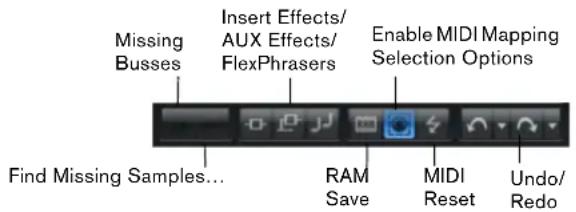
Missing Busses

If one or more bus connections could not be established, this button allows you to open the Pending Busses dialog. Here you can select alternative busses to be used instead, see "Automatic Output Connection" on page 119.
Find Missing Samples

If you load a program that cannot find all samples that it uses, the "Find Missing Samples" dialog opens, see "Finding Missing Samples" on page 58. If you close this dialog without resolving all missing samples, this button becomes available. It allows you to open the "Find Missing Samples" dialog after you have loaded a program.
Global Insert Effects/AUX Effects/FlexPhrasers
Use these buttons to switch off all insert effects, all AUX effects, or all FlexPhrasers for the plug-in at once. You can use this feature to compare sounds with and without effects, for example.
RAM Save Mode
The RAM Save function can be helpful for optimizing the performance of your system. It scans the playback of your project and unloads unused samples. Proceed as follows:
- Click the RAM Save button.
- In the dialog, click Yes to start collecting the necessary samples.
The RAM Save button starts blinking. -
Play back the project in your host application from the beginning to the end or to the point where no new notes are played.
-
Click the RAM Save button again. A dialog opens asking if you want to unload all unused samples.
-
Click Yes to unload the unused samples. If you click Yes, the button lights up, to indicate that RAM Save mode is active.
- To deactivate RAM Save and reload the unused samples, click the RAM Save button again.
→ RAM Save mode always keeps samples that are within the range of the highest and lowest note of the played programs. This also applies for unused expression layers that can be controlled via key switches. This allows you to switch between expressions within the valid note range after applying RAM Save mode.
If a program randomly triggers notes (for example different guitar slide noises), it is possible that these notes are not triggered during the RAM Save analysis process, and the samples are therefore removed. To prevent this, make sure that the highest required note is manually triggered during the RAM Save analysis.
MIDI Select
When this option is activated, played MIDI notes can be used to select zones. This also influences zone parameters displayed in the editors.
This parameter is linked to the corresponding option in the Mapping editor so that you can remote-control the option even if the Mapping editor is not visible, see “Selecting Zones with the Mapping Editor Keyboard” on page 102.
MIDI Reset
Sometimes notes can "hang", due to the plug-in losing the MIDI connection, or the plug-in receiving wrong MIDI controller data. In such a case, you can "emergency reset" the plug-in.
- Click the MIDI Reset button (the lightning icon) to send an "All Sound Off" and "Reset All Controllers" message to the plug-in.
The plug-in stops playback immediately and resets the controllers to their default values.
Undo/Redo
You can click the Undo/Redo buttons to undo or redo a single step, or you can click the small triangles to open a list of the performed steps, and go back (or forward) to that particular step.
⇒ The Undo History can also be opened as a separate editor. This allows for a better overview over the undo/redo steps.
The Keyboard Editor
The Keyboard editor contains the wheel controls, the sphere control and the internal keyboard.
Wheel Controls
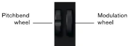
To the left of the internal keyboard, the pitchbend wheel and the modulation wheel are located.
The modulation wheel is hardwired to MIDI controller #1 which is normally used as a source in the modulation matrix, but can be used as a quick control as well. Typically, you assign the modulation wheel to a parameter of an insert effect, such as the speed of the Rotary effect.
Internal Keyboard

The internal keyboard in HALion spans the entire MIDI note range from C-2 to G8. You can use it for several purposes. The simplest one is to trigger notes just as playing them on a MIDI keyboard, but you can also drop samples onto it to import and map samples.
Display Options
You can resize the internal keyboard horizontally and vertically. A vertical resize changes the size of the individual keys and a horizontal resize defines how many octaves are visible. When the horizontal size is not sufficient to display all octaves you can use the left/right arrow buttons to both sides of the keys to shift the visible range by octaves.
For each key, the keyboard indicates whether a sample is mapped to it. Empty keys are displayed in light gray.
The following color scheme is used for the keys:
Color Description
Yellow A key switch is assigned to that key.
Beige A remapped key switch is assigned to that key.
Red The key is assigned to an expression in the Layer Alternate MIDI module.
Blue The key is assigned to a trigger pad.
Green A loop trigger note is assigned to that key.
Triggering Notes
The vertical position where you click the key defines the velocity that is used to trigger a note. Click on the lower end of a key to use the highest velocity, and click on the upper end of a key to use the lowest velocity.
- Right-click a key to open a context menu that contains information about the key. The "Assigned Zones" sub-menu displays the names of all zones that are mapped to this key, allowing you to select a zone. The Info submenu shows pitch and velocity information. Select "Clear key" to remove all assignments.
You can import samples to a specific key (or key range) by dragging them onto the keyboard, see "Importing and Exporting Samples" on page 55.
Sphere Control

The Sphere is a two-dimensional control. It allows you to adjust two parameters simultaneously, by dragging the mouse horizontally (Sphere H) and vertically (Sphere V). Typically, two parameters that belong together are assigned to the Sphere, such as cutoff and resonance.
⇒ The small triangles for indicating the horizontal and vertical axis are only available if parameters are assigned to Sphere H and V.
You can reset the sphere to the center position using the corresponding options on the context menu.
The Options Editor
The Options editor contains global settings regarding performance issues, global functions, and MIDI controllers.
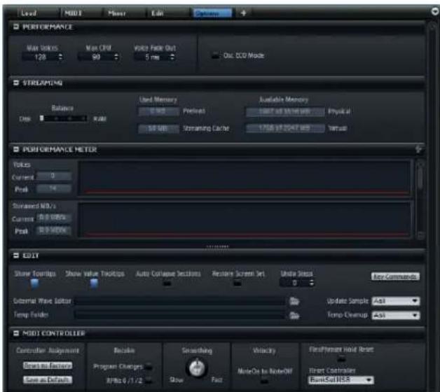
Performance Section
This section contains settings to optimize the overall CPU performance of HALion.
Max Voices
This specifies a maximum number of voices that a plug-in instance of HALion can play back simultaneously. As soon as the limit is reached, HALion starts "stealing" voices.
Max CPU
To avoid clicks caused by CPU overload, you can specify a maximum limit for the CPU load of the plug-in instance in percent. When the limit is reached, HALion automatically starts stealing voices. At a setting of 100 %, no voices are stolen.
Because HALion needs some time to react, you can get CPU peaks that exceed the limit you specified, which can lead to artifacts such as audio drop-outs. Therefore, it is advisable to set the Max CPU value a bit lower than actually needed.
Voice Fade Out
This adjusts the fade out time for voices that need to be stolen because the Max Voices or the Max CPU setting of the plug-in instance is reached.
Osc ECO Mode
When this is activated, the oscillators of synth layers run in ECO mode, and use less CPU. This allows you to play more voices, but also produces more aliasing at higher pitches.
Streaming Section
Some of the programs include up to 1 GB of samples, such as the acoustic piano. This is a large amount of data and your computer cannot load all samples into the RAM, especially if you are using all slots. Instead, HALion only loads the first milliseconds of each sample into the RAM and constantly loads more manageable portions from the hard disk while you play. With every additional note you play, the hard disk load increases, therefore, it is a good idea to load as much material as possible into the RAM beforehand. This, of course, leaves less RAM for other applications. For an optimum performance of your system, you can balance the hard disk versus RAM usage.
Balance
With this slider, you can balance the hard disk versus RAM usage.
- If you need more RAM for other applications, drag the slider to the left towards the Disk setting.
- If your hard disk is not supplying data fast enough, drag the slider to the right towards the RAM setting.
The memory displays are updated accordingly.
⇒ The Balance setting always applies to all plug-in instances. It is not saved with the project. You have to set it up only once for your computer system.
Used Memory and Available Memory
These displays provide information of the memory load in MB according to the current Balance slider setting.
Performance Meter Section
The Performance Meter section provides a variety of performance relevant information. Each meter displays the current value, the peak value, and a curve showing the changes over time. To reset all peaks, click the reset button (the lightning icon) in the title bar of the section. The following values are displayed:
Option Description
Voices The number of played voices.
Streamed MB/s The quantity of sample data that is streamed from the hard disk.
CPU Avg Load The average CPU load.
CPU Peak Load The CPU peak load.
Dropout/s The number of dropouts per second. (This can be an indicator for hard disks that are too slow.)
Preload Memory The quantity of samples loaded into the RAM of your computer.
Edit Section
This section contains some common settings of HALion and you can specify an external wave editor that you want to use for editing your samples.
⇒ The settings in the Edit section are not saved with a particular project, but affect HALion as a whole.
Show Tooltips
Activates and deactivates the tooltips.
Show Value Tooltips
When this is activated, parameters without a value field indicate their value in a tooltip when you use the control.
Auto Collapse Sections
By default, all collapsable sections can be freely collapsed and expanded. Activate "Auto Collapse Sections" to automatically collapse all other sections when expanding a specific section.
⇒ You can also right-click on the title bar of a section and select the "Auto Collapse Sections" option.
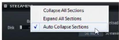
Key Commands
This opens the Key Commands dialog. For detailed information, see "Using Key Commands" on page 51.
External Wave Editor
HALion allows you to specify an external sample editor application that can be used to perform destructive offline editing on a sample, for example applying EQs, filtering, or denoising.
Here, you can specify which application to use. You can either type in the path manually or click the Browse button to navigate to the corresponding application folder. For more information, see "Editing Samples in an External Editor" on page 108.
Temp Folder
Here, you can specify a temp folder for exchanging samples between HALion and the external editor.
Update Sample
Here, you can specify the behavior of HALion when a sample is saved in the external editor. The following options are available:
Option Description
| Ask When switching back to HALion, you are asked whether the changed sample should replace the current sample. |
| Always HALion accepts the modified sample. |
| With Backup HALion accepts the modified sample and automatically creates a backup of the old sample file. |
| Never Modified samples are never accepted automatically. You have to import the modified sample manually from the temp folder. |
Temp Cleanup
After a certain period of time, HALion removes temporary sample files from the temp folder. The Temp Cleanup option allows you to specify how HALion handles these samples. The following options are available:
Option Description
| Ask You are prompted to confirm the cleanup of the temp folder. | |
| Always | Always removes temporary files without further notice. If a file cannot be deleted, an error message is shown. |
Option Description
Ignore Error Always removes temporary files without further notice. If a file cannot be deleted, no error message is shown.
Never Temporary files are never deleted. You have to delete them manually.
MIDI Controller Section
Here, you can make MIDI controller settings.
Controller Assignment
- To restore the factory MIDI controller assignments, click the "Reset to Factory" button.
- To save the current MIDI controller assignments as default, click the "Save as Default" button.
→ "Save as Default" does not include any of the MIDI controller assignments of the AUX effects.
⇒ The MIDI controller mapping is also saved with each project. This allows you to transfer your settings to other systems. The project includes the MIDI controller assignments of the AUX effects as well.
Receive Program Changes
Activate this option if you want HALion to respond to program change messages. These are generally used by General MIDI (GM) files, for example.
Receive RPNs 0/1/2
GM files can contain information about pitchbend range, coarse tuning, and fine tuning. This information is transmitted as RPNs (Registered Parameter Numbers). Activate this option if you want HALion to respond to RPNs.
Smoothing
MIDI controllers have a maximum resolution of 128 steps. This is rather low. When you use a MIDI controller as a modulation source in the modulation matrix or to remote-control a quick control, the parameter does not change smoothly, which can produce an effect often referred to as "zipper noise". To avoid this, HALion offers MIDI controller smoothing.
- Turn the control to the left to increase controller smoothing. Parameter changes triggered by MIDI controllers are less immediate.
- Turn the control to the right to decrease controller smoothing.
This way, parameters respond faster to MIDI controllers.
Velocity Note-On to Note-Off
Some keyboards do not transmit note-off velocity messages. If this option is activated, the played note-on velocity value is also used as note-off velocity for the notes.
FlexPhraser Hold Reset
Sends a global Hold Reset message to all FlexPhraser modules that are used in HALion.
The Reset Controller pop-up menu allows you to assign a dedicated MIDI controller to the FlexPhraser Hold Reset button for remote-controlling it.
Quick Controls
Quick controls allow you to remote-control any parameter inside the program. For each program and layer, eight quick controls are available. Furthermore, "Sphere H", "Sphere V", and the modulation wheel can also serve as quick controls.

The quick controls can be accessed via the Quick Controls editor for a program or layer.
Assigning Quick Controls
You can assign quick controls to a parameter of the program or one of its layers, to zones inside a program or layer, or to parameters of a MIDI module or an effect.
Proceed as follows:
-
In the Program Tree, select the element that you want to remote-control via a quick control.
-
Open the Sound editor.
-
Right-click the control to which you want to assign a quick control and open the Assign Quick Control submenu.
-
On the submenu for the program or layer, select the quick control that you want to assign.
⇒ You can assign the same quick control to different parameters. This allows you to make complex sound settings with a single control. However, you cannot assign different quick controls to the same parameter.
- To remove a quick control assignment, right-click the quick control, and select "Forget Quick Control".
- To unassign a quick control in the Quick Control Assignments section, select the quick control that you want to edit in the list on the left, right-click its assignment in the list to the right, and select "Remove Assignment".
Single Assignment vs. Multi Assignment
You can assign a quick control to a single parameter of a zone or module (single assignment) or to the same parameter of all zones inside a layer (multi assignment).
- Single assignments override multi assignments. For example, if a quick control remote-controls the cutoff of all zones inside a layer and you assign the cutoff of one of these zones to another quick control, the multi assignment is overridden by this single assignment.
- If you remove a single assignment from a parameter of a zone that is part of a layer that has a multi assignment on the same parameter of all other zones, the zone becomes part of the multi assignment again.
- If you add another zone to a layer that has a multi assignment, the added zone gets the same quick control assignments as the other zones of that layer.
Managing Quick Controls
A dedicated section of the Sound editor for programs and layers, the Quick Control Assignments section, allows you to manage and edit assigned quick controls. The eight quick controls are listed on the left. The assignments of the selected quick control are listed on the right. Each assignment is displayed in a separate row with parameters to adjust the behavior of the quick control assignment.
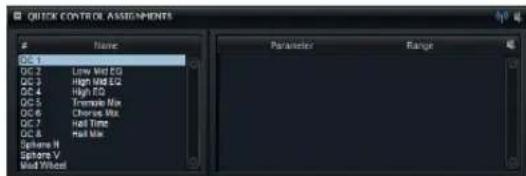
If the selected quick control has no assignments, the list on the right is empty.
Naming Quick Controls
- Open the Quick Control Assignments section of the program or layer that holds the quick control.
- In the Name column in the section on the left, click the quick control you want to rename, and enter a new name.
⇒ You can also enter the name for a quick control in the Quick Controls editor.
Duplicating Quick Controls
You can duplicate a quick control assignment using the "Duplicate Assignment" command on the context menu for the quick control.
Changing the Order of Quick Control Assignments
Drag an assignment between two other quick controls. When a line is shown, release the mouse button to insert the quick control assignment.
Replacing Quick Control Assignments
Drag an assignment onto another quick control. When a rectangle is shown, release the mouse button to replace the quick control assignment.
Assigning Quick Controls to Another Parameter
In the Quick Control Assignments section, you can reassign a quick control to another parameter.
Proceed as follows:
- Select the quick control that you want to edit.
- In the list on the right, click the parameter name to open the pop-up menu, and select a parameter from the menu.
→ You can only select parameters within the same layer, zone or module. In other words, if the quick control is assigned to a layer parameter, you cannot reassign it to a zone parameter.
Setting the Scope of Quick Control Assignments
By default, all zones inside the layer that the quick control belongs to respond to the quick control. To prevent zones inside a program from responding to the quick control, you can change the scope of the quick control for a single layer or zone.
The pop-up menu in the middle of each assignment row displays which part of the program is affected by this quick control assignment. If the name of a zone or module is displayed here, only that zone or module is affected by the quick control assignment. If the name of the program or one of its layers is displayed, all zones inside the program or layer are affected. You can change which part of the program is affected by selecting the corresponding option from the pop-up menu.
When a quick control is assigned to a parameter of the program or one of its layers, the scope of that assignment is always that program or layer only. Any layers from deeper hierarchy levels are not affected by the quick control. This behavior is different to assignments that apply to zone parameters: Assignments for all zones inside a program or layer always affect the zones that are on a deeper hierarchy level, too.
→ You can also deactivate the "Receive Quick Controls" button for certain layers, see "Receiving Quick Controls" on page 47.
Setting the Minimum/Maximum Range
You can set the minimum and maximum range for each assignment separately. This gives you better control over the parameter change.
You can set the range for a control either by specifying a minimum and maximum value on the context menu of the control itself, or by using the corresponding value fields in the Quick Control Assignments section. To edit the range graphically, click and drag the blue handles in the curve display.
Trimming the Range
The Trim Range function allows you to optimize the quick control range depending on the current parameter value.
Proceed as follows:
- Right-click the assignment in the list on the right.
- To trim the range of a single assignment, select "Trim Range". To trim the range of all quick controls, select "Trim Range of all Quick Controls".
- The minimum and maximum values are set automatically.
Whenever you change the original parameter, you have to apply the Trim Range function again to guarantee the best control range.
Setting the Default Range
This function sets the quick control to the maximum possible range.
Proceed as follows:
- In the Quick Control Assignments section, right-click the assignment on the right.
- To set the default range of a single assignment, select "Set Default Range". To set the default range of all quick controls, select "Set Default Range of all Quick Controls".
As soon as you change the original parameter in the editor section again, the Set Default Range function has to be reapplied to guarantee the best control range.
Adjusting the Curvature
You can adjust the curvature of each assignment separately.
Proceed as follows:
- On the left of the Quick Controls Assignment section, select the quick control you want to edit.
- On the right, specify the curvature in the value field between the minimum and maximum value field.
Positive values change the curvature towards logarithmic and negative values towards exponential behavior. - You can also edit the curvature graphically in the display on the right by dragging it up and down.
Setting the Behavior of Quick Control Assignments
A quick control behaves either as continuous control or as a switch. In addition, it remote-controls a parameter either in relative or absolute mode. Relative mode changes the values of the assigned parameters without loosing their relative settings. Absolute mode changes the assigned parameters by overwriting them with the current quick control value. You can specify a mode for each assignment. You can set the behavior in the context menu for the control itself or via the pop-up menu in the Quick Control Assignments section.
The following options are available:
Option Description
Relative Remote-controls the parameter values continuously. Parameter changes can still be heard.
Absolute Remote-controls the parameter values continuously. Parameter changes are overwritten.
Switch Relative Switches between the minimum and maximum value. Parameter changes can still be heard.
Switch Absolute Switches between the minimum and maximum value. Parameter changes are overwritten.
Receiving Quick Controls
In the upper right corner of the Quick Control Assignments section the Receive Quick Controls button is located. Use this button to determine whether zones inside a layer respond to quick controls. This includes any single and multi assignment to zones. Quick control assignments belonging to the layer itself are not affected.
This is useful if you assigned quick controls to the whole program and you want to exclude parts of it, such as the layer containing the instrument noises.
Proceed as follows:
- In the Program Tree, select the program or layer that you want to respond to the quick controls.
- In the Quick Control Assignments section, click the "Receive Quick Controls" button (the antenna icon).
When the Antenna button is activated, zones inside a layer respond to quick controls from outside.
Bypassing Quick Controls
To hear a sound without quick control assignments, bypass them temporarily by clicking the corresponding Mute button in the Quick Control Assignments section.
Assigning Quick Controls in the Modulation Matrix
In addition to assigning the quick controls directly to parameter controls, you can also assign them as source or modifier in the modulation matrix. This way, you can combine the quick control with other modulation sources.
Proceed as follows:
- In the Program Tree, select the zones you want to edit. Make sure that the zones are part of the program or layer with the quick controls you want to use.
- In the Sound editor, scroll down to the Modulation Matrix section.
- On the pop-up menu in the Source/Modifier column, open the Assign Quick Control submenu, and select the quick control.
The submenu lists only the quick controls that belong to the same layer or that are on a higher hierarchy level.
AI-Knob Support
HALion can be controlled with the ai-knob of Steinberg's CC121, CI 2, and CI2+ controller units.
To change a parameter value, move the mouse pointer over the control you want to change and turn the ai-knob to set the value.
Certain parameters cannot be controlled by the ai-knob due to internal differences in parameter resolution. For example, sample marker positions cannot be changed with the ai-knob because their ranges vary too much.
7
Common Editing Methods
Introduction
This chapter describes common editing methods in HALion.
Using Controls in HALion
Knobs and Sliders
Most of the editing methods are the same for knobs and sliders. The following applies:
- You can adjust the value by clicking on a knob or fader, and dragging up and down, or by using the mouse wheel.
- When you press [Alt]/[Option] and click on a knob, a small fader appears, allowing you to set the parameter.
- Press [Shift] and move the knob or use the mouse wheel to make fine adjustments.
- Press [Ctrl]/[Command] and click on a control to restore the default value.
- Knobs and sliders can be unidirectional or bidirectional. Unidirectional values, for example level values, start at a minimum value and go up to the maximum. Bidirectional controls start from the middle position and go to the left for negative and to the right for positive values.
- To navigate to the next parameter, press [Tab]. To jump backwards to the previous parameter, press [Shift]-[Tab].
When no parameter is selected inside a focused view, pressing [Tab] always jumps to the very first parameter.
Multi Selection and Parameter Controls
When several zones are selected and they do not share the exact same values, most of the controls indicate this by turning entirely or partially red. This is true for knobs, On/Off buttons, combo boxes, value fields and text faders.
For example, if you have selected 3 zones with cutoff frequency values of 1200, 1400, and 2500 Hz, the corona of the frequency knob shows a range from 1200 to 2500. The corresponding field shows the value of the focused zone in red.
⇒ More complex controls (for example the envelope editors) only show the values of the focused zone.
You can adjust the value range of a parameter using the corona of the knob. The values for the zones are distributed within the new range, keeping their relative distances.
- Drag the corona to compress or expand the value range.
- [Ctrl]/[Command]-drag the corona to adjust the upper limit of the range.
- [Alt]/[Option]-drag the corona to adjust the lower limit of the range.
On/Off Buttons
These controls normally know two states, Off and On. When you move the mouse over an On/Off button, it changes its appearance to show that you can click it.
Push Buttons
In contrast to an On/Off button, a push button only triggers an action and then goes back to its inactive state. Such buttons can be found in several places for opening menus or file dialogs.
Value Fields
You have the following options:
- To type in a value, click in the value field, start typing, and press [Enter]. If the entered value exceeds the parameter range, it is automatically set to the maximum value.
- Click in the value field and drag up or down to change the value.
- Position the mouse over the value field and use the mouse wheel to adjust the value.
- [Ctrl]/[Command]-click a value field to set it to the default value.
- [Alt]/[Option]-click a value field to bring up a fader.
- Click the up/down triangles next to the field to adjust the value.
You can adjust musical values, such as key ranges or the root key, using your MIDI keyboard.
- To enter a value with your MIDI keyboard, double-click the value field, press a key on your MIDI keyboard, and press [Return].
Using Key Commands
Key commands can be assigned to most operations that can be performed via the standalone panel of HALion. The Key Commands dialog contains a list of all available commands, arranged in a hierarchical way. When you open a category folder by clicking the "+" sign beside it, the items and functions it contains are displayed with the assigned key commands.
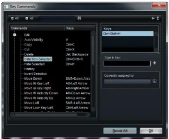
- To open the Key Commands dialog, open the Options editor, and click the corresponding button in the Edit section.
Setting Up Key Commands
-
In the Commands list on the left, select a category.
-
Click the “+” sign to open the category folder.
You can also click the global "+" and "-" signs in the top left corner to open and close all category folders simultaneously.
- Select the item to which you want to assign a key command.
Assigned key commands are shown in the Keys column and in the Keys section in the top right corner.
- Click in the "Type in Key" field, and enter a new key command.
You can choose any single key or a combination of one or several modifier keys plus any key.
- Click the Assign button above the field to assign the key command to the function.
The new key command is displayed in the Keys list.
- Click OK to close the dialog.
You can set up several key commands for the same function.
Searching for Functions
- To search for a specific function, enter its name in the search field at the top of the dialog, and click the search button.
Removing Key Command Assignments
- To remove a key command assignment, select the corresponding command in the Commands list, select the key command in the Keys list, and click the Delete button (trash icon).
Working with Presets
HALion offers two types of presets: Firstly, there are section and module presets that allow you to store and recall the setup of a specific user interface component. Secondly, there are VST presets that allow you to store and recall the settings relating to a program. During the setup, HALion installs its factory presets in a dedicated folder and creates a user folder for your own presets. The handling of presets is the same throughout HALion.

Load Preset Save
⇒ Factory presets are write-protected, but may be overwritten when a software update is executed. Presets in your user folder are never changed by the software.
Section and Module Presets
MIDI and effect modules as well as many sections in the Sound editor, such as the LFO and the Step Modulator sections, come with their own preset controls.
Loading Presets
The available presets can be selected from the presets pop-up menu at the top right of the section module.
Saving Presets
- Click the Save button (disk icon) to open a file dialog.
- Name the preset and click Save to save the parameter set as a preset.
You can modify a factory preset and save it under the same name in your user folder.
Deleting Presets
You can only delete user presets.
- Click the Delete button (trash icon).
- Click Yes to confirm.
VST Presets
Loading VST Presets
When you load a VST preset, the current program is replaced. Proceed as follows:
- On the Program Tree toolbar, click the Load icon.
- Select a VST preset and click OK.
Inserting VST Presets as Layers
- Right-click the program or layer for which you want to insert the VST preset, open the "Load/Save" submenu, and select "Load to new Layer".
- Select a VST preset and click OK. The program is inserted as an additional layer.
Alternatively, drag the VST preset from the MediaBay or file browser into the Program Tree, and drop it on a layer.
Replacing Programs and Layers with VST Presets
- Right-click the program or layer you want to replace.
- Open the "Load/Save" submenu, and select "Replace Program" or "Replace Layer".
- Select a VST preset and click OK.
Alternatively, drag the VST preset from the MediaBay or file browser into the Program Tree, and drop it on a program or layer.
Reverting to the Last Saved Program
- To revert to the last saved version of a program, open the context menu for the program, choose the Load/Save submenu, and select "Revert to last Saved Program".
Using Automation
You can automate any program that is loaded into a slot. Each slot has its own set of automation parameters, i.e., Mute, Solo, Level, and Pan. In addition, you can automate the Quick Controls of the program. You can access the automation parameters from the automation track of your sequencer software.
Automation Parameters
Each slot offers the following pre-assigned automation parameters:
Parameter Description
| Mute | This automates the Mute button of the corresponding slot. |
| Solo | This automates the Solo button of the corresponding slot. |
| Level This automates the loudness of the corresponding slot. | |
| Pan This automates the panorama position of the corresponding slot. | |
| Quick Controls 1-8 This automates the Quick Controls 1 to 8 of the program that is loaded into the slot. | |
Using Effects
HALion features AUX busses that can be used to realize classical send effects. All slot, program, and layer busses as well as zones can send signal portions to these busses. Each bus hosts up to eight insert effects, which allows you to set up complex effects. The busses are then routed to either the main plug-in output or to one of the individual outputs. Furthermore, the Mixer provides access to the master output bus. These can be used to add a global EQ or compressor to the signal chain, for example.
In the Mixer, you can set up insert effects for AUX busses.
Using the Insert Effect Slots
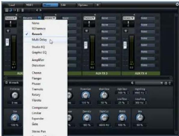
All busses, including the master bus, have eight slots for insert effects. The handling is the same for all slots:
- To assign an insert effect, click the effect slot, and select an effect from the pop-up menu.
- To remove an insert effect, click the effect slot, and select None from the pop-up menu.
The effect is removed, including its settings. - To bypass an insert effect, click the bypass button in front of the effect name.
The bypass is active when the button lights up yellow. - To edit an insert effect, click the "e" button of the corresponding slot.
You can edit only one effect at a time. The parameters of the corresponding insert effect are displayed in the bottom section.
Changing the Output Assignments
- To change the output assignment of an AUX bus, open the Output pop-up menu, and select a different output.
Adjusting the Output Levels
- Move the fader of the AUX bus.
- Alternatively, double-click the value in the field below the fader, and enter a new value.
Muting AUX Busses
- To mute an AUX bus, click the Mute icon. The icon turns yellow.
The Master Effect Bus
The master bus works similar to the AUX busses. The only difference you will find is that the master bus has no bus output selector since it is "hard-wired" to the main plug-in output (1/2).
Multi-Channel Effects
HALion comes with a large number of effects that are mainly intended for use on stereo busses. However, most of them can also be used on surround busses. In this case the effect is processed on all channels. When a bus changes from stereo to surround, the effect follows. For effects with level meters, the number of meters is adapted accordingly.
Using MIDI Modules
The MIDI modules available in HALion range from standard modules like an Arpeggiator (the so-called Flex-Phraser) to more dedicated modules that trigger specific events or deliver special modulation signals, e.g., to control articulations of sampled instruments. In general, MIDI modules process the stream of MIDI events inside a program. In addition, they are able to produce monophonic modulation signals, which can be used as sources in the modulation matrix. MIDI modules can be assigned to the whole program or just a single layer. This way, you can process the MIDI stream of the whole program or just parts of it. To cover more complex tasks, multiple MIDI modules can be assigned in series.
Inserting a MIDI Module
- In the Program Tree, select the program or layer where you want to insert the MIDI module.
- Right-click to open the context menu, open the New submenu, and select "MIDI Modules".
- Select the MIDI module that you want to insert.
- Repeat steps 2 and 3 to insert multiple modules in series.
Changing the Order of MIDI Modules
The order of the MIDI modules in the Program Tree has great influence on the processing of the MIDI events.
- To change the order, drag the MIDI modules to new positions in the Program Tree. The routing between the MIDI modules changes accordingly.
Deleting a MIDI Module
- In the Program Tree, select the MIDI modules that you want to delete.
- Open the context menu and select Delete. Alternatively, press Delete on your computer keyboard.
Bypassing a MIDI Module
Any MIDI module can be bypassed. This way, you can play the layer without the FlexPhraser or the conditions that have been set with the MegaTrig module.
- To bypass a MIDI module, click the crossed out speaker icon in the upper right corner of the caption of the MIDI module.
Assigning MIDI Modules in the Modulation Matrix
Some MIDI modules, like the FlexPhraser, directly process the MIDI events. Other MIDI modules like True Pedaling, produce modulation signals, which you must assign in the modulation matrix before you can use them.
To assign a MIDI module as source or modifier in the modulation matrix:
- In the Program Tree, select the zones you want to edit. Make sure that the zones are part of a program or layer with a MIDI module that produces modulation signals, e.g. True Pedaling.
- Open the Sound editor and scroll to the Modulation Matrix section.
- On the pop-up menu of the Source/Modifier column, open the Modulation Module submenu.
The submenu lists only the MIDI modules that belong to the same layer or that are higher up in the hierarchy. - On the submenu, select a MIDI module.
Importing and Exporting Samples
Importing Samples
HALion offers convenient functions to import samples and map them automatically on import. You can specify how the samples are mapped and also extract mapping information from sample file and folder names.
You can import samples into HALion using the Import submenu of the Program Tree context menu. In the Import Samples dialog, you can select the samples to import and make mapping settings for them.
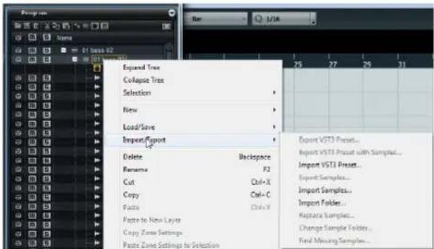
The lower section of the Import Samples dialog contains the Mapping Options.
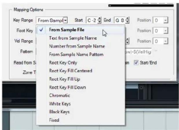
Only values between 0 and 127 can be extracted as MIDI note numbers for any of the parameters described in the following sections (e. g. "Number from Sample"). The smaller value is used as the lower limit and the higher number as the upper limit (e. g. "Sample_Name_76-121").
Setting the Key Range
On the Key Range pop-up menu, the following options are available:
Option Description
| From Sample File The samples are mapped to the key range that is saved in the file header of the sample. If this does not contain any key range information, the settings for Start and End Key are used instead. | |
| Text from Sample Name | The samples are mapped to the key range that is extracted from the name of the sample. This function searches for a key range that is defined in text form, for example "Sample_Name_B2-C#3". |
| Number from Sample Name | As above, but instead of searching for text information, this function searches for MIDI note numbers, for example "Sample_Name_59-61". |
| From Sample Name Pattern | The samples are mapped to the key range that is extracted from the name of the sample according to the name pattern you set. |
| Root Key Only Each sample is mapped to its root key only. | |
| Root Key Fill Centered | The samples are mapped to their root key. The zones expand to the left and right from the root key to fill empty spaces. |
| Root Key Fill Up The samples are mapped to their root key. The zones expand from the root key upwards to fill empty spaces. | |
| Root Key Fill Down The samples are mapped to their root key. The zones expand from the root key downwards to fill empty spaces. | |
| Chromatic The samples are mapped chromatically to the white and black keys in ascending order, starting at the key specified with the Start value. The root key is set accordingly. | |
| White Keys The samples are mapped to white keys in ascending order, starting at the key you set with the Start Key parameter. The root keys are set accordingly. | |
| Black Keys The samples are mapped to black keys in ascending order, starting at the key you specify with the Start Key parameter. The root keys are set accordingly. | |
| Fixed The samples are mapped to the key range that you specify with the Start and End Key parameters. | |
The Chromatic, White Keys and Black Keys options alter the root key. All other options map the root key according to the settings you make on the Root Key menu.
Setting the Root Key
The Root Key menu and settings allow you to specify how the root key for the samples is obtained. The following options are available:
Option Description
From Sample File The root key is read from the file header.
| Text from Sample Name | The root key is extracted from the file name. This function searches for root key information in text form, for example “Sample_Name_C#3”. |
| Number from Sample Name | The root key is extracted from the file name, as above, but instead of searching for text information, this function searches for MIDI note numbers, for example “Sample_Name_61”. |
| From Sample Name Pattern | The root key is extracted from the sample file name according to the name pattern you set. |
| Fixed | The root key is set to a fixed key, specified in the field to the right. |
If no root key information is found, the fixed root key is used.
Specifying the Velocity Range
You can specify the velocity range for the imported samples using the Vel Range parameters in the Import dialog. The following options are available:
Option Description
| From Sample File | The samples are mapped to the velocity range saved in the file header. |
| From Sample Name | The samples are mapped to the velocity range that is extracted from the file name. |
| From Sample Name Pattern | The samples are mapped to the velocity range that is extracted from the file name according to the defined name pattern. |
| From Folder Name | The samples are mapped to the velocity range that is extracted from the sample's folder name. |
| Velocity Layers | The samples are layered, that is, distributed evenly over the velocity range. |
| Fixed Velocity Range | The samples are mapped to the velocity range specified with the Start and End key values. |
If no information on the velocity range is found, the samples are mapped to the Start and End Velocity settings instead.
Obtaining Information from File and Folder Names
Depending on the mapping settings, the information for root key, key range, and velocity range is retrieved differently for file and folder names.
Using Name Patterns
Usually, names of sample files follow a certain naming scheme, for example, "Sample_C3_Key_59-61_Vel_80-100". You can extract all this information from the sample file name by selecting the "From Sample Name Pattern" option on the Key Range, Root Key, or Vel Range pop-up menus and defining a pattern in the lower part of the Mapping Options section.
You can use the Pattern field to manually edit your pattern and select variables from the pop-up menu to the right. For the Name Pattern to work, your files and folders must be named exactly as defined in the pattern, including underscores, hyphens, etc.
The following variables are available for building name patterns:
Option Description
| Key Low Number (KeyLow) | The MIDI note number is extracted and is used as the lower limit of the key range. |
| Key High Number(KeyHigh) | The MIDI note number is extracted and is used as the upper limit of the key range. |
| Key Low Text (KeyLowText) | The name of the note is extracted and is used as the lower limit of the key range. |
| Key High Text(KeyHighText) | The name of the note is extracted and is used as the upper limit of the key range. |
| Velocity Low (VelLow) | The number for the velocity value is extracted and is used as the lower limit of the velocity range. |
| Velocity High(VelHigh) | The number for the velocity value is extracted and is used as upper limit of the velocity range. |
| Root Key Number (RootKey) | The MIDI note number is extracted and is used as the root key. |
| Root Key Text(RootKeyText) | The name of the note is extracted and is used as the root key. |
Samples can only be mapped correctly on import if all samples follow the same name pattern. If no matching pattern is found, the samples use the settings for Root Key, Start and End Key and Start and End Velocity instead.
Using the Position Setting
The Position setting determines the position in the file name at which the program searches for the information.
- When this is set to "0", the entire file name is searched.
- When you select a number from the pop-up menu, the program starts searching after this number of characters. Every character is taken into account, including spaces.
The Tune and Gain Settings
The file header of the sample can contain information on the tuning and the gain of the sample. On import, this information is retrieved as well.
To switch off reading the Tune and Gain information during import, deactivate the corresponding options below the Pattern field.
Listening to Samples before Import
You can listen to the samples before importing them. The corresponding controls can be found above the Mapping Options section in the Import dialog.
The following controls are available:
Option Description
| Play | Click the Play button to play back the focused sample. |
| Stop | Click the Stop button to stop playback of the sample. The play locator jumps back to the sample start. |
| Pause | Click the Pause button to stop playback of the sample, click again to continue playback. |
| Loop | Activate the Loop button to play back the sample repeatedly. |
| Auto Play | Activate Auto Play to automatically start playback of the selected sample. |
Level This fader adjusts the playback level.
Position The position slider displays the playback position within the sample. To select another position for playback, click on the slider or drag the handle to the new position.
Sample Zone Presets
When importing samples, HALion uses a "Default" zone preset. This sets all zone parameters to default values, but excludes sample-specific parameters (Sample Start, Sample End, Loop Start, Loop End, etc.). You can modify this preset in the Sound editor for a zone and save it as "Default" to your user preset directory. HALion then uses this preset instead.
Importing Folders
Usually, sample collections are organized in folder structures, where each velocity layer or each key group is saved in a separate folder. In HALion, you can import complete folders, including their subfolders.
Proceed as follows:
- In the Program Tree, right-click the selected program or layer.
- On the context menu, open the Import/Export submenu, and select "Import Folder...".
- In the Import Folder dialog, click the button to the right of the Folder field, navigate to the folder that you want to import, and click OK.
- Activate "Include Subfolders" to import samples from deeper hierarchy levels too.
- To create layers that correspond to the hierarchy of the subfolders on disk, activate "Create Layers from Sub-folders".
- Set up the Mapping Options as needed.
They are identical to the options in the Import Samples dialog.
- Click OK.
Finding Missing Samples
There might be situations where loaded programs cannot find the samples they use. This can happen if the referenced samples are located on a different drive and the drive name has changed, or because the program was created on a different computer system.
When this happens, the "Find Missing Sample" dialog opens, showing a list of all samples that are missing, with additional information about the format, size, and creation date. The list groups all samples that are located in the same subfolder.
Entering a Search Path
Below the list you can enter the search path to find the missing samples.
All the subdirectories are searched before the results are displayed, therefore the search takes longer if you specify entire drives.
Start the Search
- Once you have specified the search path, click the Start Search button to start the search process.
If the search only finds a single result for each missing sample, the sample path is automatically corrected in the program and the sample disappears from the "Missing Files" list. If all samples are found, the dialog is closed.
Using Favorite Paths
If a path might be helpful for future searches, you can add it to the search path list. The next time the dialog opens, it allows you to select one or multiple predefined paths to specify which places to include in the search.
- To add a path, click the "+" sign.
Multiple Results
It can happen that samples are found in several places. If this is the case, an additional "Found File" list appears below the "Missing File" list. This shows the available samples and their file locations.
- To select a sample or a complete folder that is to be used to resolve the missing samples, double-click on it in the "Found Files" list.
Each sample or folder that is resolved this way disappears from the "Missing Files" list.
Once all samples are resolved the dialog closes.
Search Options
By default, HALion searches for samples that do not only have the same file name, but also correspond in terms of time, size and format information. Only if all of the information are identical, a sample is considered "found". However, you can exclude this information by activating the "Ignore File Time and Size" and "Ignore Audio Format" options.
Exporting Samples
Samples can be exported together with the corresponding program or layer as VST presets, or on their own. In both cases, you use the "Export Samples..." option on the Program Tree context menu. For VST presets, the corresponding dialog has additional preset options.
- To export a VST preset, select the program or layer in the Program Tree. On the context menu, open the Import/Export submenu, and select "Export Samples...". This opens the Export Preset with Samples dialog.
- To export samples without a preset, select the samples in the Program Tree. On the context menu, open the Import/Export submenu, and select "Export Samples...". This opens the Export Samples dialog.
→ Samples loaded from HSB files or protected VST sound files cannot be exported.
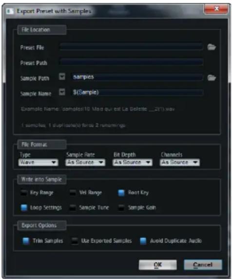
Creating Folders using Variables
You can automatically create folders when exporting samples using variables for the Sample Path.
Proceed as follows:
-
In the Sample Path field, set the cursor at the position where you want to insert the variable.
-
On the pop-up menu next to the field, select a variable.
-
Where necessary, complete the file path by typing in a back-slash (Win) or a slash (Mac).
You can combine several variables, separating them with hyphens, spaces, etc.
The resulting sample path is displayed in the Example Name field.
The following variables are available:
Option Description
| Sample Folder(SampleFolder) | Creates a folder with the name of the folder of the original samples. |
| Layer Structure(Structure) | Creates folders following the structure of the selected program or layer. |
| Layer Name(Layer) | Creates a folder with the name of the layer. |
| Program Name(Program) | Creates a folder with the name of the program. |
| Sample Rate(SampleRate) | Creates folders that are named according to the sample rate of the samples. |
| Bit Depth(BitDepth) | Creates folders that are named according to the bit depth of the samples. |
| Date(Date) | Creates a folder with the name of the current system date (in the format yymmdd). |
| Time(Time) | Creates a folder with the name of the current system time (in the format hhmm). |
Renaming Samples
You can also rename the samples automatically on export using sample name variables. You can combine several variables.
Proceed as follows:
- In the Sample Name field, set the cursor at the position where you want to insert the variable.
- On the pop-up menu next to the field, select a variable.
- If needed, add further variables. You can combine several variables, separating them with hyphens, spaces, etc.
The resulting sample name is displayed in the Example Name field.
The following variables are available:
Option Description
| Sample Name$(Sample) | This variable uses the file name of the original sample. Use it if you do not want to modify the sample file names. |
Option Description
| Sample Folder(SampleFolder) | The name of the folder of the original samples is used in the file name. |
| Zone Name(Zone) | The name of the zone is used in the file name. |
| Layer Name(Layer) | The name of the layer is used in the file name. |
| Program Name(Program) | The name of the program is used in the file name. |
| Key Low Number(KeyLow) | The MIDI note number of the lower limit of the key range is used in the file name. |
| Key High Number(KeyHigh) | The MIDI note number of the upper limit of the key range is used in the file name. |
| Key Low Text(KeyLowText) | The name of the note of the lower limit of the key range is used in the file name. |
| Key High Text(KeyHighText) | The name of the note of the upper limit of the key range is used in the file name. |
| Velocity Low(VelLow) | The number of the lower limit of the velocity range is used in the file name. |
| Velocity High(VelHigh) | The number of the upper limit of the velocity range is used in the file name. |
| Root Key Number(RootKey) | The MIDI note number of the root key is used in the file name. |
| Root Key Text(RootKeyText) | The name of the root key is used in the file name. For example, (Sample)_(RootKeyText) appends the name of the root key to each sample file name. |
| Sample Rate(SampleRate) | The sample rate of the samples is used in the file name. |
| Bit Depth(BitDepth) | The bit depth of the samples is used in the file name. |
| Date(Date) | The system date (in the format yymmdd) is used in the file name. |
| Time(Time) | The system time (in the format hhmm) is used in the file name. |
Example Name Field and Status Messages
The Example Name display informs you about the sample path and name resulting from your settings.
Below, a status message informs you how many samples are saved and if duplicate names are created. For example, if two zones in the Program Tree have the same name, and you use the variable “\$(Zone)”, this results in duplicate file names. However, file names must be unique. Therefore, the duplicate file names are automatically numbered.
Samples loaded from HSB files or protected VST Sound files cannot be exported. The status message informs you if such protected files exist.
Files that are in use by HALion or another application cannot be overwritten. In this case, choose a different location for the samples.
Some systems have problems with file names longer than 32 characters. Therefore, it is best to use file names that do not exceed this number.
Setting the File Format
You can export the samples as Wave or AIFF files and specify a sample rate and bit depth for them, if needed.

Do not change the sample rate of looped samples, because this can cause audible artifacts.
Including Zone Settings
You can include zone settings when saving the samples. When you import these samples back into HALion, they automatically get these settings.
The following settings can be written into the sample file:
Option Description
| Key Range Saves the Key Low and Key High settings of each zone with the samples. | |
| Velocity Range | Saves the Velocity Low and Velocity High settings of each zone with the samples. |
| Root Key Saves the Root Key setting of each zone with the samples. | |
| Loop Setting Saves the loop settings of each zone with the samples. | |
| Sample Tune Saves the Tune setting of each zone with the samples. | |
| Sample Gain Saves the Gain setting of each zone with the samples. | |
Setting Up General Export Options
In the Export Options section, you can make general settings for the export. The following settings are available:
Option Description
| Trim Samples | Trims the samples to their actual length, specified with the Sample Start and Sample End parameters of the zone. |
| Use Exported Samples | Updates the sample references of the zones to use the exported samples. |
| Avoid Duplicate Audio Files | Prevents samples that are used by several zones from being exported as duplicate audio files. |
If a sample has several zones and these zones have different loop settings, HALion creates duplicates of the file.
Replacing Samples
The Replace Samples function allows you to exchange the sample that is used to play back one or multiple zones. The zone-specific settings like Pitch, Filter, or Amplifier are not modified by this.
Replacing a Single Sample
- In the Program Tree or Mapping editor, select the zone for which you want to replace the sample.
- On the context menu for the zone, open the submenu "Import/Export", and select "Replace Sample". A file dialog opens.
- Locate and select the new sample and click OK.
Replacing Multiple Samples
- In the Program Tree or Mapping editor, select the zones for which you want to replace the samples.
- On the context menu for one of the zones, open the Import/Export submenu, and select "Replace Samples".
- At the bottom of the file dialog, select the method for replacing samples that you want to use.
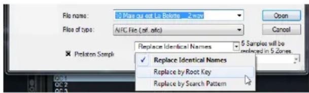
The following methods are available:
| Option Description | |
| Replace Identical Names | The samples are only replaced by new samples if their names are identical.Typically, this is the case if you processed the samples and saved them under the same name in a different location on your hard disk. |
| Replace by Root Key | The samples are replaced by new samples that have a matching root key, regardless of the file name. |
Option Description
| Replace by Search Pattern | This method can be used if only parts of the sample name have changed, for example, due to processing or saving.Enter the part of the name that has changed in the text field. Samples are replaced if the remaining parts of the sample name are identical.For example, if the name "Sample_Mix_1_C3.wav" has changed to "Sample_Mix_2_C3.aiff", enter"*Mix_2*.aiff" in the text field. |
4. Locate the new samples.
The info text in the lower right section shows you how many samples are replaced in how many zones. If no samples are found, you have to select another method for finding matching samples.
5. Click OK.
Auditioning Samples before Replacing Them
To listen to the samples before replacing the old ones, activate the Prelisten Sample option and use your MIDI keyboard.
Detecting the Root Key
To listen to the samples with the correct pitch, you have to select how to detect the root key of the new sample. The following options are available:
Option Description
| Root Key from Sample File | The root key is read from the file header of the sample file. |
| Root Key Text from Sample Name | The root key is extracted from the sample file name. This function searches for the root key in text form, for example “Sample_Name_C#3”. |
| Root Key Number from Sample Name | The root key is extracted from the sample file name. This function searches for the root key as a MIDI note number, for example “Sample_Name_61”. |
| Keep Zone Root Key | Instead of using the root key of the new sample, the root key of the zone is used.This option is only available when replacing a single sample. |
The "Change Sample Folder" Option
The “Change Sample Folder” option on the Import/Export submenu of the Program Tree context menu allows you to relocate samples. This is useful if you processed the samples and saved them in a new location without changing their names.
Importing Third-Party Sampler Programs
HALion allows you to import a wide range of sampler formats from third-party manufacturers. When importing those formats, HALion translates as many parameters as possible.
HALion only reads files from standard file systems and not from proprietary formats like Akai CDs.
→ Programs that are saved in a protected format cannot be imported.
Using the Import Editor
The Import editor is divided into the Import Tree on the left and the results list on the right. The Import Tree shows one or multiple folder locations and allows you to select one or more folders. Folders that contain importable programs have a green folder icon, other folders have a yellow folder icon. The result list shows all importable layers that are located in the selected folders and allows you to import them via drag and drop.
To import a program, proceed as follows:
-
On the Import editor toolbar, click the "Select Folder" button.
-
Navigate to the folder that you want to import and click OK.
The selected folder structure is scanned and the Import Tree shows the content of this folder and its subfolders.
-
In the Import Tree, select the subfolder that contains the layers that you want to import.
-
Drag the subfolder or selected layers to the Program Tree, the Program Table, or the Slot Rack.
You can import folders from the Import Tree that are marked green with three lines, or drag selected layers from the results list.
-
If the program does not contain the samples, you are asked to specify the folder in which the samples can be found.
-
Specify the folder in which you want to save the imported samples.
The HALion program is created.
Adding a Folder
You can add additional folders to the Import Tree using the Add Folder button.
Specifying a Destination Folder
The folder specified in the "Destination Folder" field is used to save samples from bank or container files, such as GigaSampler files (.gig"). You can type in the path manually or click the button to the right to navigate to a specific directory.
If you do not specify a destination folder for sampler formats that use container files, you are asked to do so on the first import operation. This folder is then used for all following operations.
When programs are imported, HALion creates a folder for each program. The name of the folder corresponds to the name of the imported program. Inside this folder, HALion creates a subfolder in which the corresponding samples are saved, if necessary.
Hide Empty Folders
This option allows you to hide all folders that do not contain any importable programs.
Add to MediaBay
This option allows you to automatically create VST presets for each imported program in the user presets folder of HALion, thereby making them available in the MediaBay. When this option is deactivated, no preset is saved and the program is only available in the current HALion instance. If you want to use the program in other projects, you have to save it first.
Importing Sliced Loops
HALion features a Slice Player that can play back sliced audio loops. You can import sliced loops in the common REX1 and 2 formats or drag and drop sliced events directly from Cubase.
Importing REX Loops
The import process for REX files includes several steps. First, the slice information is used to create a sample zone per slice. These sample zones are then mapped to the keyboard. The range starts with C3 and uses as many zones as slices are defined in the loop. The slice information is also used to create a MIDI phrase that is loaded into a Slice Player module.
To import REX files, you have the following options:
- Drag a REX file from the Windows Explorer or Mac OS Finder to the Program Tree and drop it on a program or layer.
- Open the context menu for a program or layer, open the Import/Export submenu, select "Import Samples...", and select the file via a file dialog.
When working with REX1 files, HALion can directly play audio from these files. For REX2 files HALion first extracts a WAV file and saves it in the same folder as the REX file.
Importing Sliced Audio Events from Cubase
You can directly import sliced audio events from Cubase by drag and drop. When dropping a sliced audio event in the Program Tree, HALion recognizes that the event contains positional information for the different slices. In the Import Samples dialog, the button "Create Sliced Loop" becomes available. If you click this button, HALion creates a sample zone for each slice and adds a Slice Player containing the required MIDI information. Any further mapping options are ignored.
⇒ You can also drag selected audio events (from multiple tracks) from a Cubase project into the Program Tree to create a sliced loop.
Playing back Sliced Loops
After the import, you can play back the loop in its original form or in a transposed version. By default, the original loop is played using C2 (#48), but you can specify another key using the Key Follow and Center Key parameters. Pressing a key below C3 plays transposed versions of the original loop. The keyboard range above C3 provides the slice sample zones, which are triggered by the slice player, but can also be triggered manually while the loop is playing.
Make sure that the very last event ends with the loop end and not before. Otherwise the generated loop will be too short and will not run in a perfect cycle.
If the REX file or Cubase audio event contains more than 128 slices, HALion automatically creates additional layers including MegaTrig modules preconfigured to use key switches. That way, you can create up to 1024 zones distributed over up to 32 layers.
The Slice Player Controls
Most of the Slice Player controls are the same as for the FlexPhraser MIDI module. These are described in detail in the section "The FlexPhraser" on page 141. The controls that differ for the Slice Player are described in the following sections.
Slice Player Presets
At the top right of the Program Tree, you can load and save presets for the Slice Player. These presets are saved in a global folder and can be accessed from any project you are working in.
Restart Mode
Depending on the selected Restart mode and your playing, you can restart playback from the beginning of the loop.
You can select one of the following options:
Option Description
| Off The loop runs continuously and does not restart upon note changes. |
| First Note | The loop restarts when a note is triggered and no other notes are already held. |
Option Description
Each Note The loop restarts each time a note is triggered.
| Sync to Host | Select this to align the loop with the beats and measures of your host application. The loop aligns to the beats and measures each time you start the transport. |
Start
This parameter allows you to shift the start of the loop in steps of 1/4 notes. The length of the loop is shortened accordingly.
Length
This parameter allows you to shorten the length of the loop in steps of 1/4 notes.
⇒ The control range of the parameters Start and Length varies with the original length of the loop.
Quantize
This parameter allows you to set up a quantization grid, in fractions of beats. You can also specify dotted and triplet values. This way, you can force the timing of the slices to play back only at the selected note value.
Amount
This parameter defines how much of the quantization grid is applied. A value of 100 % means the slices play back only at the Quantize note value you specified. Smaller values move the notes only partially towards the next Quantize note value. With a value of 0 % no quantization is applied at all.
Key Follow
Here you can adjust the pitch modulation by note number. Set this parameter to positive values to raise the pitch with notes above the center key. Use negative values to lower the pitch with notes above the center key. At +100 %, the pitch follows the played note exactly.
⇒ The Key Follow parameter is limited to the keys that trigger the entire loop. It does not affect the keys that play the single slices.
Center Key
This parameter determines the MIDI note that is used as the central position for the Key Follow function.
Random
You can shuffle the playing order of the slices randomly, by activating the Random button. To play the slices with their original order, deactivate the Random button.
The overall timing does not vary through this. Only the playing order of the slices is affected.
- Use the Depth parameter to adjust how much the playing order of the slices is shuffled. Lower this value to keep the playing order of slices on the main beats. Raise this value to vary the playing order of slices on the offbeats as well.
- Click the Trigger button to trigger a new shuffle. Note that this changes the pattern number.
- Use the Pattern option to recall a certain random pattern, by entering its pattern number in the value field.
Exporting the Loop Sequence
You can export the loop sequence as a MIDI part for your host sequencer.
Proceed as follows:
-
Click the MIDI connector icon (to the right of the Random options) and drag it into the Project window of your host sequencer application.
This creates a MIDI part at the drop position, on an existing or a new MIDI track. -
Assign the MIDI track to the corresponding slot in HALion.
Using Variations
By activating Random and by adjusting the Tempo, Tempo Scale, Swing, Gate Scale, Quantize, Amount, Start, and Length parameters, you can save your settings as up to eight variations. For further information, see "Working with FlexPhraser Variations" on page 143.
The Loop, Sync, Hold, Trigger Mode, Restart Mode, Key Follow, and Center Key parameters are not part of the variations.
Editing Programs and Layers in the Sound Editor
Introduction
The Sound editor for programs and layers lets you access parameters that are set globally for the whole program or individual layers. For example, you can transpose the pitch, adjust level and pan, and limit the playback to a certain area on the keyboard.
Programs and layers share the same set of parameters because they are nearly identical.
The Main Section
The main section contains basic settings for programs and layers.
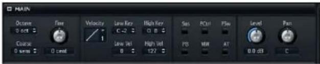
Octave
Transposes the pitch in octave steps.
Coarse
Transposes the pitch in semitone steps.
Fine
Detunes the pitch in cents (1/100 of a semitone).
Level Velocity Curve
Defines how incoming MIDI velocity values are re-mapped before they are sent to the program or layer. By default, the curve is set to linear, meaning that incoming and outgoing values are identical. The characteristic of each curve is displayed by a small icon.
Low Key
Defines the lowest key on which the program or layer is triggered.
High Key
Defines the highest key on which the program or layer is triggered.
Low Vel
Defines the lowest velocity on which the program or layer is triggered.
High Vel
Defines the highest velocity on which the program or layer is triggered.
Sus, FCtrl, FSw, PB, MW, and AT
The Filter options allow you to filter incoming MIDI controllers.
Level
Adjusts the level of the layer. This parameter works as an offset to the zone settings.
Pan
Defines the position of the layer in the stereo panorama. This parameter works as an offset to the zone settings.
The Trigger Section
The Trigger section allows you to control the triggering and releasing behavior.
![TRIGGER And Messaging Key Switch Mode Permanent Filter Ctrl in Release Off And Velocity Mode Velocity Fade Transport Start Key Default Switch C-2 C-2 Repetarding System Sistemas Velocity Mode Controller Controller Modulation [1]](/content/2026/04/671619/images/6c498478aa21174aedaf12891ef2534077c937b62fb02e95bc02cdf9adc5f74e.jpg)
Ind MegaTrig
If you want the key switch assignments across different layers to work individually, activate the individual MegaTrig management of these layers. This can be necessary when two layers with different key switches are used together in one program. For more information about the MegaTrig module, see "MegaTrig" on page 148.
Transpose
Transposes the key switches that you set up for the MegaTrig module.
Start Key
Defines the key that is used as the lowest key switch.
Key Switch Mode
Defines how long a key switch is active:
- If set to Permanent, the key switch stays active until another key switch is used.
- If set to Temporary, the key switch is only active for as long as the corresponding key is pressed.
Default Switch
Specifies the default key switch that is active when you load a program, i. e. before you used the first key switch. The default key switch is also used in Temporary mode when no key switch is pressed.
⇒ If you set Default Switch to a note value that is not assigned as a key switch, the lowest key switch is automatically used as the default key switch.
Filter Ctrls in Release
Filters out MIDI controllers in the release phase. Modulation destinations that are using controllers keep their value after the note-off message. The following settings are available:
Option Description
Off MIDI controllers are processed in the release phase.
On MIDI controllers are filtered out.
Inherit The zones of this layer follow the behavior that was specified for the parent layer.
Repedaling
On an acoustic piano, you can repedal the sustain after releasing the sustain pedal for as long as the strings vibrate. The effect is that the strings play on. You can achieve a similar effect with the Repedaling option. If you release and press the pedal within the release of the amplitude envelope, the envelope jumps to the decay segment, resuming at the current level of the release.
Sustain
Enables sustain for the program or layer. When you use the sustain pedal, notes keep playing until you release the pedal.
Sostenuto
Enables sostenuto for the program or layer. Notes that are held while pressing the sostenuto pedal sustain. Successive notes do not sustain.
Ind Velocity Mode
Sample-based instruments often use crossfade techniques to optimize the switching between samples with different velocities. Crossfades are set up in the Mapping editor, see "Fading and Crossfading Zones" on page 100.
Activate this option to apply the Velocity Mode settings to the selected layer and its children.
Velocity Mode
The switching or crossfading between zones can be controlled via velocity or MIDI controller. The following modes are available:
Option Description
Note-on The velocity is used to trigger the zones.
| Controller | A MIDI controller is used to replace the velocity, i.e. the controller value is used to select the zones. The note-on message triggers the zones selected by the controller. Only the zones that belong to the corresponding velocity are played back. |
| Continuous | A MIDI controller is used to replace the velocity. Depending on the "Velocity Fade" setting, the controller continuously fades between the zones or switches zones directly. Therefore, all zones belonging to a key are played back. |
Controller
Here, you select the controller that is used when the velocity Mode option is set to Controller or Continuous.
- For the most realistic playback of instruments that use crossfade techniques, activate "Velocity Fade" and set "Velocity Mode" to Continuous.
- To save voices during playback of instruments that use crossfade techniques, deactivate "Velocity Fade" and set "Velocity Mode" to Note-on.
- Generally, setting "Velocity Mode" to Controller and activating "Velocity Fade" is a good compromise between performance optimization and realistic playback.
Velocity Fade
Activate this option to use the velocity crossfades that are specified in the Mapping editor. When this option is deactivated or if no crossfades have been set up, zones switch directly between the different velocities.
The Voice Management Section
The Voice Management section allows you to control the maximum number of notes that you can play and to set conditions for note stealing and triggering.
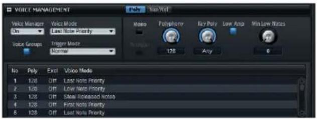
Voice Manager
The Voice Manager option controls which Voice Management settings are applied to the selected layer. The following settings are available:
Option Description
| Off The layer automatically uses the Voice Management set- tings of the layer that is one step up in the hierarchy. If there is no layer with active Voice Management settings, the settings of the program are used. |
| On You can make separate Voice Management settings for the selected layer. |
| Program The settings of the program are used, regardless of any Voice Management settings made for layers higher up in the hierarchy. |
Voice Mode
The Voice Mode parameter determines which notes are stolen during playback and whether new notes are triggered when the Polyphony setting is exceeded. The following settings are available:
Option Description
| Low Note Priority Low notes have playback priority over higher notes.- If you exceed the maximum number of notes by playing a lower note than the ones that are held, the highest note is stolen and the new note is triggered.- If you exceed the maximum number of notes by playing a higher note than the ones that are held, no note is stolen and no new note is triggered. | |
| High Note Priority | High notes have playback priority over lower notes.- If you exceed the maximum number of notes by playing a higher note than the ones that are held, the lowest note is stolen and the new note is triggered.- If you exceed the maximum number of notes by playing a lower note than the ones that are held, no note is stolen and no new note is triggered. |
| First Note Priority Older notes have playback priority over newer notes.- If you exceed the maximum number of notes while older notes are still being held, no notes are stolen. New notes are only triggered if a free voice is available. | |
| Last Note Priority New notes have playback priority over the first played notes.- If you exceed the maximum number of notes, the first played notes are stolen in chronological order (First in/First Out) and the new notes are triggered. | |
| Steal Lowest Amplitude | New notes have playback priority over notes with a low amplitude.- If you exceed the maximum number of notes, the note with the lowest amplitude is stolen and the newest note is triggered. |
| Steal Released Notes | New notes have priority over notes that enter the release phase.- If you exceed the maximum number of notes, the oldest note that is in its release phase is stolen and the new note is triggered.- If no note is playing in release and you exceed the maximum number of notes, the first played notes are stolen in chronological order and the new notes are triggered. |
Trigger Mode
The Trigger Mode parameter defines the trigger behavior for new notes.
The following settings are available:
Option Description
| Normal Triggers a new note when the previous note gets stolen.The sample and the envelope of the new note are triggered from the start.To minimize discontinuities, use the Fade Out parameter of the zone (see “Voice Fade Out” on page 43). |
| Resume Does not always trigger a completely new note:- If the new note stays within the same zone, the envelope is retriggered, but resumes at the level of the stolen note.The pitch of the zone is set to the new note.- If the new note plays in a different zone, the sample and the envelope of the new note are triggered from the start. |
| Legato Does not always trigger a completely new note:- If the new note stays within the same zone, the envelopes keep running. The pitch of the zone is set to the new note.- If the new note plays in a different zone, the sample and the envelope of the new note are triggered from the start. |
When Resume or Legato is selected, you might hear an unnatural attack, depending on the sample. To avoid this, activate the "Use Start Range" option for the sample zone (see "Use Start Range" on page 77).
Voice Groups
By assigning zones to a voice group, you can set their polyphony individually. In addition, you can manage the polyphony across zones that are not part of the same layer. Furthermore, zones can steal notes from each other, regardless of whether they are in the same layer.
The voice group parameters are shown below the Voice Management settings.
The maximum number of notes that you can play in a voice group is limited by the Polyphony setting of the corresponding program or layer.
Assigning Zones to Voice Groups
Proceed as follows:
- In the Program Tree, select the zones that you want to add to a voice group.
- Open the Sound editor for the zones.
-
In the Voice Control section, select the Trigger tab.
-
On the Voice Group pop-up menu, select a voice group.
Usually, the voice group numbers relate to the voice groups of the program. If the zone is part of a layer with active voice groups, the numbers relate to the voice groups of the layer instead.
Editing Voice Groups
The Voice Management parameters of voice groups are edited using the columns in the table below the Voice Management section.
Exclusive Groups
When voice groups belong to the same exclusive group, they cannot be played back simultaneously. The last triggered voice group has priority over the previously playing voice groups. Any previously playing voice groups of the same exclusive group are cut off.
A typical example for assigning voice groups to an exclusive group is a drum set where the closed hi-hat cuts off the open hi-hat.
- To assign a voice group to an exclusive group, click the "Excl" field of the voice group, and select a number from the pop-up menu.
The Poly Tab
The Poly tab contains the polyphony settings for programs and layers.
Mono
The Mono parameter activates monophonic playback. For solo instruments, this usually results in a more naturally sounding performance.
Mono can also be used for programs that use dedicated note-off layers. When the played note is released, the note-off layer is triggered.
Retrigger
The Retrigger option is only available in Mono mode. When Retrigger is activated, a note that was stolen by another note is retriggered if you still hold the stolen note when releasing the new one. This way, you can play trills by holding one note and quickly and repeatedly pressing and releasing another note, for example.
Polyphony
When you play a note, one or multiple zones can be triggered. Each triggered zone equals a voice. The number of voices you trigger with each note is displayed in the Voices field of the program. Use this parameter to set an upper limit for the number of notes that can be played simultaneously in polyphonic mode.
If a program has a lower Polyphony value than its layers, the maximum number of notes you can play is limited by the Polyphony value of the program.
Key Poly
With Key Poly (Key Polyphony), you can specify an upper limit for the number of notes that can be played for a key. The last played notes have priority. For this parameter to have an effect, the polyphonic mode needs to be activated.
Key Polyphony is limited by the Polyphony setting. If the Polyphony setting is lower, this value is used instead.
Low Amp
By default, the "oldest" note is removed first when notes are stolen due to a Key Poly limitation. Activate Low Amp if you want the note with the lowest amplitude to be removed instead.
Min Low Notes
Defines the number of low notes that cannot be stolen, regardless of the Voice Mode setting.
The Sus/Rel Tab
The Sus/Rel tab contains the sustain and release settings for programs and layers.
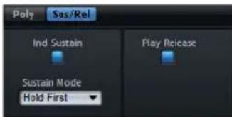
Ind Sustain
Activate "Ind Sustain" to use individual sustain settings for the selected programs or layers.
Sustain Mode
While holding the sustain pedal, HALion plays back notes that you play repeatedly up to the Key Polyphony value. When you lift the sustain pedal, the notes of the keys that are no longer held enter the release phase. Depending on the selected Sustain Mode, the notes of the keys that are still held either keep playing, or also enter the release phase.
The following settings are available:
Option Description
Hold Loudest The loudest note keeps playing.
Hold Last The last note you played keeps playing.
Hold First The first note you played keeps playing.
Hold All All notes keep playing.
Release All All notes enter the release phase.
Play Release
By default, the release phase of stolen notes is not played back and the notes fade out in the time specified by the Fade Out parameter of the zone. Activate this option to fade out the notes with their normal release phase instead.
The Variation Groups Section
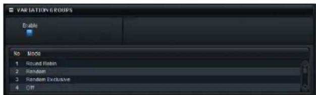
To avoid the so-called machine gun effect that occurs when the same sample is triggered repeatedly, you can create programs that use several samples for the same key and velocity range. These samples can then be triggered alternately as variations. To define which samples are triggered as variations, you can assign them to one the variation groups. In the Variation Group section you can also specify the alternation mode for each variation group.
- To use the Variation Group feature, activate the Enable button and select one of the available modes for each group.
The following settings are available
Option Description
Off All variations are triggered simultaneously.
Round Robin All variations are triggered alternately in a fixed order.
Random All variations are triggered randomly. Individual variations can be triggered repeatedly.
Random Exclusive All variations are triggered randomly. No variation is directly repeated.
If no variation groups are activated, all zones play simultaneously. To avoid this, activate the variation groups for the program or layer containing the zones and assign the zones to the different variation groups.
Assigning Zones to Variation Groups
Proceed as follows:
- In the Program Tree, select the zones that you want to add to the voice group.
- Open the Sound editor for the zones.
- In the Voice Control section, select the Trigger tab.
- On the Variation Group pop-up menu, select a voice group.
→ Usually, the variation group numbers relate to the variation groups of the program. If the zone is part of a layer with active variation groups, the numbers relate to the variation groups of the layer instead.
The Quick Control Assignments Section
The Quick Controls Assignments section allows you to manage and edit the assigned quick controls. It is described in detail in the section "Managing Quick Controls" on page 45.
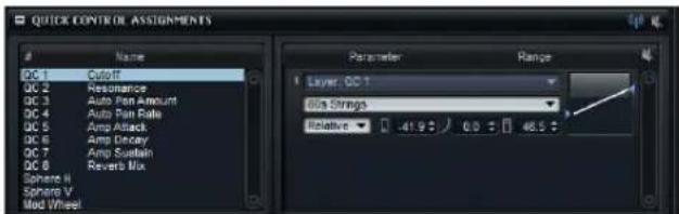
The Note Expression Section
Cubase's Note Expression technology is essential for creating realistic instrument performances. Note Expression allows you to create automated modulations for each note. In general, HALion supports Note Expression for volume, pan, and tuning. With any of HALion's programs you can automate these parameters in Cubase for each note. But HALion can do more: In programs that give you access to the modulation matrix, you can assign up to eight so-called Note Expression controllers to any available modulation destination. These work in addition to the pre-assigned pitch, pan, and level modulations. When the Note Expression controller is assigned, you can specify a name for it to make it available in Cubase.
The eight Note Expression controllers of a program are shared by all zones. This means that the Note Expression controller data affects all zones simultaneously. Depending on how the Note Expression controllers are set up in the modulation matrix, each zone might react differently.
When you use HALion with older versions of Cubase or other host applications that do not support Note Expression, you still have access to the Note Expression section and you can see Note Expression controllers in the modulation matrix. However, they will not have any influence on the program.
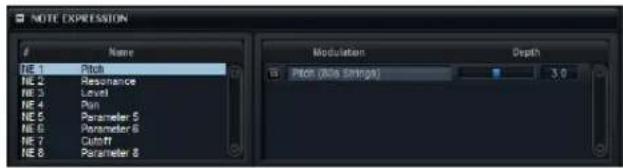
The Note Expression section shows the eight Note Expression controllers on the left (NE1 to NE8) and the assigned modulation destinations on the right. This gives you a quick overview of how Note Expression controllers are routed in the modulation matrix and what their influence on the sound will be. One Note Expression controller can be assigned to several destinations.
Naming Note Expression Controllers
By default, a Note Expression controller is given the name of the modulation destinations it is assigned to. However, you can also rename them. After this, any further assignments will not change the name.
- To rename a Note Expression controller, click in the Name field of the selected controller and enter the new name.
Bypassing the Note Expression Controller
Each Note Expression controller has a Bypass button that allows you to deactivate the effect of the controller.
⇒ The Bypass button is linked to the Bypass button of the corresponding modulation destination in the modulation matrix.
Changing the Modulation Depth
The Depth slider adjusts the intensity of the Note Expression modulation. This allows you to change the modulation without having to go to the modulation matrix first.
⇒ The slider is linked to the Depth slider of the corresponding modulation destination in the modulation matrix.
Editing Zones in the Sound Editor
Introduction
The Sound editor for synth and sample zones contains the zone parameters in HALion. It allows you to modify the settings for a single zone, for multiple selected zones or for all zones at the same time.
If not expressly stated, the functions described in this chapter apply to both synth and sample zones.
All functions and parameters described here also apply to the Zone Editor.
Global Zone Settings
The global section at the top of the Sound editor allows you to set up basic zone parameters.

Focused Zone
On the Focused Zone pop-up menu, you can select a zone for editing when several zones are selected in the Program Tree.
Low Key/High Key
These parameters determine the lowest key and the highest key on which the zone is triggered.
Low Vel/High Vel
These parameters determine the lowest velocity and the highest velocity on which the zone is triggered.
Root Key
The root key determines the pitch of the zone. Samples can contain root key information embedded in the file, which means that when loaded, they are automatically mapped to the corresponding keys.
Zone Type
HALion allows you to change a sample zone into a synth zone and vice versa. If you switch a sample zone to a synth zone, the sample oscillator is replaced by the synth oscillators. You can select the zone type from this pop-up menu.
Editing Selected Zones or All Zones
When working in the Sound editor, you can apply your editing either to the selected zones (SEL) or to all zones (ALL), depending on the setting of the corresponding button on the toolbar.
All zones are affected by the editing.
Absolute and Relative Editing
When editing multiple zones, you can either change values absolutely for all the zones (ABS) or make relative changes (REL), depending on the setting of the corresponding button on the toolbar.
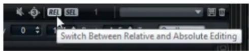
- When you use absolute editing and you change a parameter from 50% to 60% for one zone, all other zones will also be set to 60% .
- When you use relative editing and you change a parameter from 50% to 60% in one zone, another selected zone that was set to 70% is set to 80% .
Relative changes can be made for all parameters that can be adjusted continuously. Changes of parameters that select one of multiple modes or switch between two states are always absolute.
HALion 3 compatibility
The button to the left of the REL/ABS button lights up when you load an FXP file from HALion 3 to indicate that HALion 4 is in compatibility mode. This way, FXP files sound like they did in HALion 3. If you deactivate the compatibility button, some modulations will sound different.
The Voice Control Section
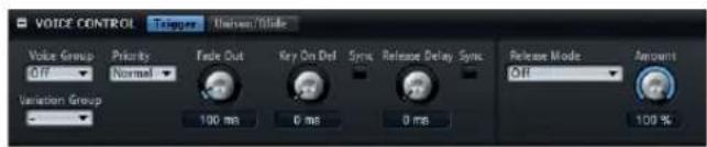
The Voice Control section of the Sound editor has two tabs: Trigger and Unison/Glide.
The Trigger Tab
On the Trigger tab, you can specify the triggering of a zone.
Voice Group
You can set the polyphony of a zone individually, by assigning it to one of 128 voice groups. The settings of voice groups can be edited in the Voice Management section of the program or layer. For more information on voice groups, see "Voice Groups" on page 70.
Variation Group
To avoid the so-called machine gun effect that occurs when the same sample is triggered repeatedly, you can create programs that use several samples for the same key and velocity range. These samples can then be triggered alternately as variations. To define which samples are triggered as variations, you can assign them to one of 16 variation groups. Use the Variation Group pop-up menu to specify the alternation mode for the different variation groups.
Priority
Each zone you trigger corresponds to a voice. When the numbers of played voices (zones) exceed the Maximum Voices setting of the plug-in instance, zones are cut off and replaced by other voices. This is called "voice stealing". Use this parameter to specify a priority for this behavior. Zones with higher priority can steal zones with lower priority, but not vice versa. If there are no zones with lower priority, zones of the same priority are stolen. Zones with the priority Hold steal only from lower priorities, but not from themselves.
To specify how fast the zones are stolen, use the "Voice Fade Out" parameter in the Options editor.
Fade Out
Whenever a voice is stolen because a polyphony limit is reached, it is faded out. You can specify this fade out time for each zone, which allows you to adapt it to different signal types. For example, you might want to cut a stolen crash cymbal zone less abruptly than a stolen hi-hat zone.
Key On Delay
With this parameter, you can delay the playback of the zone by a specified time or a note value.
- To synchronize the delay time to the host tempo, activate the Sync button and select a note value from the pop-up menu. To change the selected note value to a triplet, activate the "T" button.
With Sync deactivated, the delay is specified in milliseconds. With Sync activated, the delay is specified in fractions of beats.
Release Mode and Amount
The parameters Release Mode and Amount determine how loud the release samples are played back. Release samples play back the sound of an instrument when the note ends. For example, this can be the noise of the damper touching down on the piano string, or the reverb tail of an instrument that was recorded in a concert hall. By setting the release mode, the level of the release samples can be controlled from different sources, for example. The Amount parameter adjusts how much the selected option affects the level of the note-off samples.
To set up the playback of release samples, proceed as follows:
- In the Program Tree, place the note-on and note-off samples into separate layers.
- Add a MegaTrig Module to the note-off layer and set the playing condition to "Note-off".
- Select all note-off samples.
- In the Sound editor, open the Voice Control section, and make settings for Release Mode and Amount.
The following settings are available:
Option Description
Off Deactivates the Release Mode. The level of the note-off sample is controlled only by the amplifier section of the zone.
Option Description
| Note-on Env The level of the note-off sample is controlled bythe Amplitude Envelope of the associated note-onsample: The note-off sample is played back withthe level that the amplitude envelope has at themoment when the note-off sample is triggered.In order to find the associated note-on sample, themappings of the note-on and note-off samplesmust overlap. HALion takes the last running note-on sample as the associated one. |
| Note-off Env The level of the note-off sample is controlled bythe amplitude envelope of the note-off sample:The note-off sample is played back with the levelthat its amplitude envelope has at the momentwhen the note-off sample is triggered. |
| Note-on Vel The level of the note-off sample is controlled bythe incoming MIDI note-on velocity. |
| Note-off Vel The level of the note-off sample is controlled bythe incoming MIDI note-off velocity. |
| Current Amplitude The level of the note-off sample is controlled bythe current amplitude of the associated note-onsample. |
| Random The level of the release sample is controlled by arandom value. Use the Amount control to set thedepth of the random value. |
The Unison/Glide Tab
The Unison/Glide tab has the following parameters:
Unison
Unison allows you to trigger multiple voices simultaneously with each note you play. When you activate the Unison option, the following parameters become available:
Option Description
| Voices | This determines the number of voices that are triggered simultaneously (max. 8). |
| Detune | Use this parameter to detune the pitch of each unison voice in cents. This produces a fatter sound. |
| Pan Use this parameter to spread the unison voices across the stereo panorama. The higher the value, the broader the stereo image. | |
| Delay With this parameter you can introduce a small random delay for each unison voice. With a value of 0 %, all unison voices are triggered at the same time. Values from 1% to 100% add a random delay to each unison voice. The higher the value, the more random the delay. This is especially useful to avoid comb filter effects with two or more slightly detuned samples, which can occur if you play them back at exactly the same time. | |
Glide
You can use the Glide parameter to bend the pitch between notes that follow each other. You achieve the best results in Mono mode.
When you activate the Glide option, the following parameters become available:
Option Description
| Time This specifies the time needed to bend the pitch from one note to the other. | |
| Sync | Activate this option to synchronize the delay time to the host tempo. Select a note value from the pop-up menu. To change the selected note value to a triplet, activate the "T" button. |
| Mode Here, you can specify whether the glide time is constant and independent from the note interval (Constant Time) or if the time changes with the note interval (Constant Speed). When Constant Speed is selected, larger intervals result in longer glide times. | |
| Curve | You can select one of three curve types to define the glide behavior: With the Linear curve, the pitch glides at continuous speed from the start to the end pitch. With the Exponential curve, the pitch starts gliding at higher speed and decelerates towards the end pitch. This behavior is similar to the natural pitch glide produced by a singer. With the Quantized curve, the pitch glides in semitones from the start to the end pitch. |
| Fingered | Activate this parameter to glide the pitch only between notes that are played legato. |
⇒ If you use Cutoff, Amplitude and Pan Key Follow, the corresponding parameters also change with the Glide effect.
Glide Groups
You can assign zones to Glide Groups. This way, the glide effect can be set independently for the zones. This allows you to set up zones with overlapping Key Range and different settings of Glide Time, for example.
Use Start Range
If a new note plays in a different zone with a different sample assigned, the new sample is used to glide to the new pitch. Depending on the sample, this can produce an unnatural attack. To avoid this, activate "Use Start Range". When this is activated, the sample does not start from the beginning, but from the position you set with the Sample Start Range parameter.
The Pitch Section
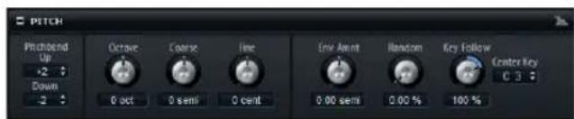
On the Pitch section for synth and sample zones, you can make settings for tuning and pitch modulation. The following parameters are available:
Pitchbend
Here, you can set the range of the pitch modulation that is applied when you move the pitchbend wheel.
Octave
Here, you can adjust the pitch in octave steps.
Coarse
Here, you can adjust the pitch in semitone steps.
Fine
This parameter allows you to fine-tune the pitch in cents (hundredths of a semitone).
Env Amnt (Envelope Amount)
This parameter determines how much the pitch is affected by the pitch envelope.
Random
This parameter allows you to randomly offset the pitch with each played note. Higher values cause stronger variations. At a setting of 100 %, the random offsets can vary from -6 to +6 semitones.
Key Follow
Here you can adjust the pitch modulation by MIDI note number. Set this parameter to positive values in order to raise the pitch the higher you play. Use negative values to lower the pitch the higher you play. At a setting of +100 %, the pitch follows the played note exactly.
Center Key
This specifies the MIDI note that is used as the central position for the Key Follow function.
The Oscillator Section
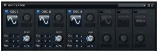
The Oscillator section for synth zones offers six sound sources: three main oscillators, the sub oscillator, the ring modulation and the noise generator. To create interesting electronic spectra, you can mix any of these sound sources. The resulting signal is sent to the Filter and Amplifier sections for further sound shaping.
The three main oscillators (OSC 1, OSC 2 and OSC 3) offer different wave shapes and algorithms.
- You activate an oscillator by clicking its On/Off button.
Make sure to deactivate any oscillator functions that are not needed to save processing power.
OSC 1/2/3 Type
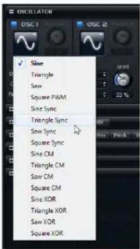
The Oscillator Type defines the basic sound character of the oscillator. The pop-up menu lists the waveforms (Sine, Triangle, Saw or Square), followed by the algorithm (PWM, Sync, CM or XOR). The combination of waveform and algorithm controls the sound of the oscillator.
- To select an oscillator type, click the icon that indicates the wave shape for OSC1, OSC2, or OSC3 and select the wave shape and algorithm you want to use from the pop-up menu.
The following algorithms are available:
Algorithm Description
| PWM(Pulse Width Modulation) | PWM is only supported by the square waveform. The Waveform parameter sets the ratio between the high and low value of the square wave. A setting of 50% produces a pure square wave. With settings below or above 50% the oscillator produces rectangular waves. |
| Sync This algorithm provides different hard-sync oscillators, where each is a combination of a master and slave oscillator. The wave shape of the slave oscillator (Sine, Triangle, Saw or Square) is reset with each full wave cycle of the master oscillator. This means that a single oscillator can produce a rich sync-sound without using other oscillators as slave or master. The Waveform parameter adjusts the pitch of the slave oscillator, producing the typical sync sound. | |
| CM(Cross Modulation) | This algorithm provides a combination of two oscillators where a master oscillator is modulating the pitch of a slave oscillator (Sine, Triangle, Saw or Square) at the rate of the audio sample. The Waveform parameter adjusts the pitch ratio between slave and master oscillator, resulting in a sound close to frequency modulation. |
Algorithm Description
| XOR(Exclusive or) | This algorithm compares two square waveforms with an XOR operation. Depending on the outcome of the XOR operation, the waveform shape of a third oscillator (Sine, Triangle, Saw or Square) is reset. The Waveform parameter adjusts the pitch ratio of the square oscillators resulting in a sound close to ring modulation of the third oscillator. |
⇒ Except for PWM, all algorithms support the Sine, Triangle, Saw and Square wave shapes. PWM supports Square wave only.
⇒ The waveform parameters for OSC1, OSC2 and OSC3 can be assigned as modulation destinations in the modulation matrix.
OSC 1/2/3 Waveform
The waveform parameter allows you to modify the sound of the oscillator algorithm. Its effect depends on the selected oscillator type.
OSC 1/2/3 Octave (Oct)
Here, you can adjust the pitch in octave steps.
OSC 1/2/3 Coarse (Crs)
Here, you can adjust the pitch in semitone steps.
OSC 1/2/3 Fine
This parameter allows you to fine-tune the pitch in steps of cents (hundredths of a semitone).
OSC 1/2/3 Level
This adjusts the output level of the oscillator.
The waveform, pitch and level of oscillator 1, 2, and 3 can be modulated separately in the modulation matrix.
Sub Oscillator (SUB)
The pitch of the sub oscillator is always one octave below the overall pitch of the synth zone. If you modulate the pitch of the synth zone, the pitch of the sub oscillator follows.
- To activate and deactivate the sub oscillator, click its On/Off button.
The following parameters are available:
Parameter Description
| Sub Oscillator Type | Here, you can select the wave shape of the sub oscillator. You can choose between Sine, Triangle, Saw, Square, Pulse Wide and Pulse Narrow. |
| Sub Oscillator Level | This adjusts the output level of the sub oscillator. |
Ring Modulation (RING)
Ring modulation produces sums and differences between the frequencies of two signals.
- To activate ring modulation, click the On/Off button.
The following parameters are available:
Parameter Description
| Ring Modulation Source 1/2 | This allows you to select the sources to be ring mod-ulated. You can select OSC1 or Sub as Source 1 and OSC2 or OSC3 as Source 2. |
| Ring Modulation Level | This adjusts the output level of the ring modulation. |
Noise
The Noise parameter is used for non-pitched sounds. In addition to standard white and pink noise, there are also band-pass filtered versions of white and pink noise.
- To activate the noise generator, click its On/Off button.
The following parameters are available:
Parameter Description
| Noise Type Here, you can select the sound color of the noise. You can choose between White, Pink, White BPF (BPF = band-pass filtered), and Pink BPF. |
Noise Level This adjusts the output level of the noise generator.
Sub level, ring modulation level and noise level can be modulated separately in the modulation matrix (see "The Modulation Matrix Section" on page 92).
The Sample Oscillator Section
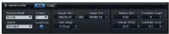
The sample oscillator controls various playback parameters as well as loop parameters.
The Main Tab
Playback Mode
The following playback modes are available:
Option Description
| Normal The sample is played back from the beginning to the end. If any loops are defined they are played according to their loop settings. | |
| Reverse The sample is played backwards, ignoring any loop settings. | |
| One Shot The sample is played back from the beginning to the end, ignoring any loop settings. | |
| Reverse One Shot | The sample is played back from the end to the beginning, ignoring any loop settings. |
In One Shot and Reverse One Shot mode, the zones ignore any MIDI Note Off messages. All envelopes and LFOs play until their sustain is reached and then remain on this level for as long as the sample plays back. Any release segments of the envelopes and LFOs are not played. However, if you activate One Shot mode in the Envelope section, the release nodes of the envelopes are included in the playback.
Quality
When samples are not played with their original pitch or tempo, HALion calculates the transposed versions in real time using algorithms that require different CPU performance depending on the Quality setting.
Changing the quality mode is particularly noticeable in the high frequencies. The higher the setting, the better the suppression of artifacts. For samples with little high-frequency content, you can safely use the "Standard" option. For programs that use different samples for every key (no resampling is necessary) you should always use the "Standard" option to save computing power.
Preload
HALion provides two different ways of working with sample data. A sample can either be loaded completely into RAM or it can be streamed from the hard disk. However, when samples are streamed, HALion needs to preload a portion of these samples to be able to play a voice without having to search for the sample data first. The size of this preload buffer can be set in the Options editor. The Pre-load setting enables you to adapt this buffer size for individual sample zones by setting a multiplier from 1 to 16. Increasing the buffer size can be useful if a sample can be transposed in a wide range and HALion needs to read out the sample data faster, for example.
If you set Preload to its maximum, HALion preloads the complete sample. This option is useful for smaller samples.
Sample Start Range
The Sample Start Range parameter allows you to determine the range for sample start offset modulation. When Sample Start is selected as a modulation destination in the modulation matrix, the Sample Start Range parameter controls the range, that is the sample portion that is affected by the start offset modulation. If this parameter is set to zero, no sample start modulation is performed.
For example, if note-on velocity is used to modulate the sample start parameter, a high key velocity starts playback later in the sample, and the range of this modulation is determined by the Range Start parameter.
Fixed Pitch
When a sample zone is triggered by a MIDI note other than the one defined by the Root Key setting, the sample is normally pitched accordingly. When Fixed Pitch is activated, the relation between played note and root key is disregarded and all keys play the sample just like it was recorded.
⇒ You can still apply the usual pitch modulations in the Pitch section and set the sample to follow the keyboard according to the Key Follow Root Key setting.
The Loop Tab
The options on the Loop tab are identical with the loop options on the Loop tab of the Sample editor, see "Creating Loops" on page 108.
The Filter Section
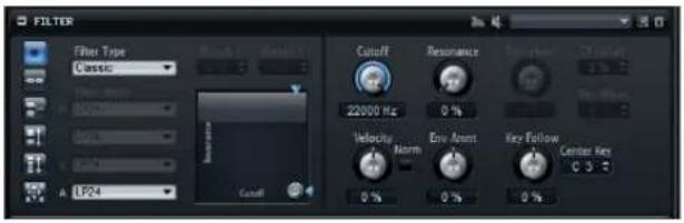
The Filter section for synth and sample zones allows you to adjust the tone color of the sound.
Filter Type
By selecting the filter type, you specify the basic sound character of the filter. Note that filters without distortion use less processing power.
The following filter types are available:
Filter type Description
| Off The filter section is switched off. | |
| Classic This filter type offers 24 filter shapes with resonance. | |
| Tube Drive | This filter type offers a lot of character by adding warm, tube-like distortion. You can set the amount of tube drive with the Distortion parameter. |
| Hard Clip | This filter type adds bright, transistor-like distortion. You can set the amount of hard clipping with the Distortion parameter. |
| Bit Red (Bit Reduction) | This filter type adds digital distortion by means of quantization noise. You can adjust the bit reduction with the Distortion parameter. |
| Rate Red | This filter type adds digital distortion by means of alias-ing. You can adjust the rate reduction with the Distortion parameter. |
| Rate Red KF | As above, but with Key Follow: The rate reduction follows the keyboard, so the higher you play, the higher the sample rate. |
| Waldorf This filter type offers 14 filter shapes, including two comb filters. | |
| HALion 3 This filter type offers the 5 legacy filter shapes from HALion 3. | |
Filter Mode
The buttons on the left of the Filter section determine the overall filter structure. The filter types provide the following options:
Filter mode Description
| Single Filter | This mode uses one filter with one selectable filter shape. |
| Dual Filter | This mode uses two separate filters connected in series. |
| Serial | You can select the filter shapes for each filter independently. The parameters Cutoff and Resonance control both filters simultaneously. However, you can offset the cutoff and resonance of the second filter with the parameters CF Offset and Res Offset. |
| Dual Filter | This mode uses two separate filters connected in parallel. |
| Parallel | You can select the filter shapes for each filter independently. The parameters Cutoff and Resonance control both filters simultaneously. However, you can offset the cutoff and resonance of the second filter with the parameters CF Offset and Res Offset. |
| Morph 2 | This mode morphs between filter shape A and B. You can select the filter shapes for filter shape A and B independently. Adjust the morphing with the Morph Y parameter. |
| Morph 4 | This mode morphs sequentially from filter shape A to D. You can select the filter shapes for filter shape A, B, C, and D independently. Adjust the morphing with the Morph Y parameter. |
| Morph XY | This mode morphs freely between the filter shapes A, B, C, and D. You can select the filter shapes for filter shape A, B, C, and D independently. Adjust the morphing with the Morph X and Morph Y parameters. |
For compatibility reasons, the filter types HALion 3 and Waldorf are included. These filters always use Single filter mode.
Filter Shape
Each filter type offers 24 different filter shapes. By selecting the filter shape you determine which frequencies are affected. Depending on the chosen filter mode, you can either select one, two, or four shapes.
Filter shape Description
| LP24 | Low-pass filter with 24 dB/oct. Frequencies above the cutoff are attenuated. |
| LP18 | Low-pass filter with 18 dB/oct. Frequencies above the cutoff are attenuated. |
| LP12 | Low-pass filter with 12 dB/oct. Frequencies above the cutoff are attenuated. |
| LP6 | Low-pass filter with 6 dB/oct. Frequencies above the cutoff are attenuated. |
| BP12 | Band-pass filter with 12 dB/oct. Frequencies below and above the cutoff are attenuated. |
Filter shape Description
| BP24 | Band-pass filter with 24dB/oct. Frequencies below and above the cutoff are attenuated. |
| HP6+LP18 | High-pass filter with 6dB/oct plus low-pass filter with 18 dB/oct (asymmetric band-pass filter). Frequencies below and above the cutoff are attenuated. Attenuation is more pronounced for the frequencies above the cutoff. |
| HP6+LP12 | High-pass filter with 6dB/oct plus low-pass filter with 12 dB/oct (asymmetric band-pass filter). Frequencies below and above the cutoff are attenuated. Attenuation is more pronounced for the frequencies above the cutoff. |
| HP12+LP6 | High-pass filter with 12dB/oct plus low-pass filter with 6 dB/oct (asymmetric band-pass filter). Frequencies below and above the cutoff are attenuated. Attenuation is more pronounced for the frequencies below the cutoff. |
| HP18+LP6 | High-pass filter with 18dB/oct plus low-pass filter with 6 dB/oct (asymmetric band-pass filter). Frequencies below and above the cutoff are attenuated. Attenuation is more pronounced for the frequencies below the cutoff. |
| HP24 | High-pass filter with 24dB/oct. Frequencies below the cutoff are attenuated. |
| HP18 | High-pass filter with 18dB/oct. Frequencies below the cutoff are attenuated. |
| HP12 | High-pass filter with 12dB/oct. Frequencies below the cutoff are attenuated. |
| HP6 | High-pass filter with 6dB/oct. Frequencies below the cutoff are attenuated. |
| BR12 | Band-reject filter with 12dB/oct. Frequencies around the cutoff are attenuated. |
| BR24 | Band-reject filter with 24dB/oct. Frequencies around the cutoff are attenuated. |
| BR12+LP6 | Band-reject filter with 12dB/oct plus low-pass filter with 6 dB/oct. Frequencies around and above the cut-off are attenuated. |
| BR12+LP12 | Band-reject filter with 12dB/oct plus low-pass filter with 12 dB/oct. Frequencies around and above the cut-off are attenuated. |
| BP12+BR12 | Band-pass filter with 12dB/oct plus band-reject filter with 12 dB/oct. Frequencies below, above and around the cutoff are attenuated. |
| HP6+BR12 | High-pass filter with 6dB/oct plus band-reject filter with 12 dB/oct. Frequencies below and around the cut-off are attenuated. |
| HP12+BR12 | High-pass filter with 12dB/oct plus band-reject filter with 12 dB/oct. Frequencies below and around the cut-off are attenuated. |
| AP | All-pass filter with 18dB/oct. Frequencies around the cutoff are attenuated. |
| AP+LP6 | All-pass filter with 18dB/oct plus low-pass filter with 6 dB/oct. Frequencies around and above the cutoff are attenuated. |
| HP6+AP | High-pass filter with 6dB/oct plus all-pass filter with 18 dB/oct. Frequencies around the cutoff are attenuated. |
Cutoff
Here, you can adjust the cutoff frequency of the filter. The effect depends on the selected filter type.
X/Y Control
The X/Y control allows you to adjust two parameters simultaneously. This is especially useful with the morphing filters, where the X/Y control adjusts the mix between the filter shapes. For the other filter modes, the X/Y control adjusts cutoff and resonance. Depending on the selected filter type, the X/Y control adjusts different parameters:
Filter Description
| Single, Dual Serial & Dual Parallel | The X/Y control adjusts the cutoff frequency on the horizontal and resonance on the vertical axis. |
| Morph 2 and 4 | The X/Y control adjusts the morphing between the filter shapes on the vertical (Morph Y) axis. The horizontal axis adjusts the cutoff frequency. |
| Morph XY | The X/Y control adjusts the morphing between the filter shapes AD and BC on the horizontal (Morph X) and AB and DC on the vertical axis (Morph Y). |
Resonance
This parameter emphasizes the frequencies around the cutoff. For an electronic sound, increase the resonance. At higher resonance settings, the filter self-oscillates, which results in a ringing tone.
Distortion
This parameter adds distortion to the signal. The effect depends largely on the selected filter type. At higher settings, it creates a very intense distortion effect.
This parameter is only available for the Tube Drive, Hard Clip, Bit Red, Rate Red and Rate Red KF filter types.
CF Offset
For the dual filters, this parameter allows you to offset the cutoff frequency of the second filter (filter shape B).
Res Offset
For the dual filters, this parameter allows you to offset the resonance of the second filter (filter shape B).
Velocity
This parameter adjusts the cutoff modulation from velocity. Set this parameter to positive values to increase the cutoff with higher velocities. Use negative values to decrease the cutoff with higher velocities.
Norm
The Norm option allows you to normalize the velocity values that are used to modulate the filter. This means that the velocity range for the zone is remapped to a full velocity range.
For example, if a zone ranges from 40 to 80 on the mapping velocity scale, an incoming velocity of 40 results in a velocity value of 0 being sent to the cutoff, an incoming velocity of 80 results in 127. This way, you can adapt velocity-layered zones in such a way that each zone starts with a damped filter setting and opens completely towards the zone above.
Fatness
This parameter (only available for the algorithms Waldorf and HALion 3) adds a warm, tube-like filter distortion to the signal.
Env Amnt (Envelope Amount)
Use this parameter to adjust the cutoff modulation from the filter envelope. Setting negative values inverts the direction of the modulation from the filter envelope.
Key Follow
Here, you can adjust the cutoff modulation using the note number. Set this parameter to positive values to raise the cutoff with notes above the center key. Use negative values to lower the cutoff with notes below the center key. At +100 % the cutoff follows the played pitch exactly.
Center Key
This parameter determines the MIDI note that is used as the central position for the Key Follow function.
Bypass
The Bypass buttons in the top right of the section allow you to listen to the zone without modulation of the filter envelope and without any filtering.
The Amplifier Section
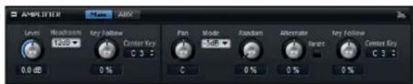
The Amplifier section has two tabs: Main and AUX.
The Main Tab
The Main tab gives you access to the Level and Pan settings of the zone.
Level
Here, you can adjust the loudness of the zone.
Headroom
Use this parameter to specify the headroom for polyphonic playback. By default, HALion uses a headroom of 12 dB. For monophonic programs, such as drum loops, set the headroom to 0 dB. If you work with low polyphony values, a headroom of 6 dB is sufficient.
Key Follow
Use this parameter to control the volume depending on the note pitch. Positive values mean that the volume is higher the higher the notes you play. With negative values, the volume decreases the higher the notes you play.
Center Key
This parameter determines the MIDI note that is used as the central position for the Key Follow function.
Pan
Here, you can set the position of a sound in the stereo panorama. At a setting of -100 %, the sound is panned hard left and at +100 %, it is panned hard right.
Mode
With this option you can specify how the loudness changes across the stereo panorama. The following modes are available:
- 0dB: This option works like a balance control. Setting the pan control towards the left fades out the right channel and vice versa. At the center position, the loudness is not cut.
- -3dB: This option uses the cosine/sine pan law The loudness is cut by -3dB at the center position, but the energy is preserved when moving the source signal across the stereo panorama. The -3dB option sounds more natural. The transition from hard left to hard right sounds much smoother than with the 0dB or the -6dB setting.
- -6dB: This option uses the linear pan law. The loudness is cut by -6dB at the center position, and the energy is not preserved when moving the source signal across the stereo panorama. The -6dB option sounds more synthetic. The transition from hard left to hard right sounds more abrupt than with the -3dB setting.
- When set to Off, no panning is applied.
Random
This parameter allows you to offset the pan position randomly with each played note. Higher values cause stronger variations. At a setting of 100 %, the random offsets can vary from fully left to fully right.
Alternate
This parameter allows you to alternate the pan position each time you play a note. If you want to start panning on the left, use negative values. Use positive values to begin on the right. At a setting of +100 %, the first note plays hard right, the second note hard left, and so on.
Reset
The initial pan position is set once when HALion is loaded. Then, HALion counts each note you play to determine the next pan position. To reset this counter, click the Reset button next to the Alternate control.
Key Follow
Here you can adjust the pan modulation via the MIDI note number. Set this parameter to positive values to offset the pan position towards the right for notes above and towards the left for notes below the center key. Use negative values to offset the pan position towards the left for notes above and towards the right for notes below the center key. At the maximum setting of +200 %, the pan position moves from hard left to hard right within two octaves: Fully left is reached one octave below and fully right is reached one octave above the center key.
Center Key
This parameter determines the MIDI note that is used as the central position for the Key Follow function.
The AUX Tab
The AUX tab allows you to send the zone to the four global AUX busses and to directly route the zone to one of the plug-in output busses.
AUX 1-4
In HALion, you can send the zone signal to the four global AUX busses. You can control the signal level that is sent to the busses with the knobs AUX 1-4.
Output
HALion allows you to route a zone directly to one of the output busses. In this case, the zone does not pass through the layer, program and slot busses.
The Envelope Section
The Envelope section for synth and sample zones gives you access to the four envelopes of the zone: Amp, Filter, Pitch, and User. Each of these is a multisegment envelope with up to 128 nodes. The Amp, Filter and Pitch envelopes are pre-assigned to the amplitude, the filter cutoff frequency and the pitch of the zone. You can adjust the pre-assigned modulations in the corresponding sections of the zone. The purpose of the User envelope is freely definable.
- Click the Amp button to display the parameters of the amplifier envelope.
The amplifier envelope shapes the volume over time.
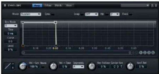
- Click the Filter button to display the parameters of the filter envelope.
The filter envelope controls the cutoff frequency to shape the harmonic content over time.
- Click the Pitch button to display the parameters of the pitch envelope.
The pitch envelope modulates the pitch over time. The pitch envelope is bipolar, which means it allows for negative and positive values to bend the pitch.
- Click the User button to display the parameters of the freely assignable user envelope.
It is bipolar, which means it allows for negative and positive values, for instance, to modulate the pan from left to right.
Zooming and Navigating in the Graphical Envelope Editor
The vertical axis of the graphical envelope editor displays the level. The horizontal axis displays the time.
You can zoom in and out in the following ways:
- To zoom in on the horizontal axis, use the "+" button to the right of the scrollbar below the graphical editor.
- To zoom out, click the "-" button.
- In the timeline, click and drag up or down to zoom in or out at the current position.
- To zoom to a certain region, hold [Alt]/[Option] and drag the mouse over the region.
You can navigate to a certain position in the following way:
- Drag the scrollbar to the left or right to scroll the envelope editor.
- Click in an empty space next to the scrollbar to jump to the corresponding position in the envelope editor.
- Click the triangles to the left and right of the scrollbar to scroll through the envelope step by step.
Envelope Zoom Snapshots
Envelope zoom snapshots save the current state of the graphical envelope editor. For example, by saving two envelope zoom snapshots, one for the beginning and one for the end of the envelope, you can conveniently switch between editing the attack and release of the envelope.
Saving and Loading Envelope Zoom Snapshots
To the right of the scrollbar, you can find three numbered buttons that allow you to save and load envelope zoom snapshots for the current envelope editor. An envelope zoom snapshot also includes the zoom factor and scroll position of the graphical envelope editor. These are restored when loading the snapshot.
- To save the current state of the graphical envelope editor as snapshot, [Shift]-click one of the numbered buttons to the right of the scrollbar.
- To load a previously saved envelope zoom snapshot, click the corresponding button. The button color changes to green indicating the snapshot is active. Zooming or scrolling with the graphical envelope editor deactivates the envelope zoom snapshot.
Editing the Envelope
Each multisegment envelope has up to 128 nodes with the Time, Level and Curve parameters. The nodes and their parameters specify the overall shape of the envelope. You can edit one or multiple nodes in the graphical envelope editor or by typing in values.
Selecting Nodes
- You select a node by clicking on it in the graphical editor. Selected nodes turn light blue. The focused node is indicated by an orange frame. The focused node displays its parameters in the value fields to the left of the graphical envelope editor.
- When multiple nodes are selected, you can use the Node pop-up menu above the value fields to set the focus to a different node without losing the current selection.
- [Shift]-click on a node to add it to the selection. Selected nodes are edited together.
- You can select multiple nodes by drawing a rectangle around the nodes with the mouse.
- With a single node selected, use the left or right arrow key to select the next or previous node. In a multiselection, the focused node changes and the previous or next node within the multiselection is focused.
Adjusting the Time Parameter
The Time parameter specifies the period of time between two nodes. Depending on the Sync mode, the Time parameter is displayed in milliseconds and seconds, or fractions of beats.
To set the Time parameter, select the nodes you want to edit, and enter a value in the Time field.
You can also adjust the Time parameter in the graphical envelope editor, by dragging the nodes left or right, to decrease or to increase the time span.
- For a higher resolution, hold [Shift] while moving the nodes.
- Hold [Ctrl]/[Command] while dragging to limit the movement to the time axis (horizontal positioning only).
Adjusting the Level Parameter
The Level parameter specifies the amplitude of the envelope at the position set by the Time parameter. The Amp and Filter envelopes are unipolar. Therefore, the value range for the level is 0% to +100% (positive values only). The Pitch and User envelopes are bipolar, the value range for the level is from -100% to +100% (negative and positive values) for these envelopes.
→ You can change the polarity of the envelopes in the modulation matrix, for instance, to map the range of the Amplifier Envelope (unipolar) to Pan (bipolar). However, the envelopes always display their values with their default polarity.
To set the Level parameter, select the nodes you want to edit and enter a value in the Level field.
You can also adjust the Level parameter in the graphical envelope editor by dragging the selected nodes up or down, to decrease or increase the levels.
- For a higher resolution, hold [Shift] while moving the nodes.
- Hold down [Alt]/[Option] while dragging to limit the movement to the level axis (vertical positioning only).
Adjusting the Curve Parameter
The Curve parameter allows you to adjust the curvature between two nodes from linear to logarithmic or exponential behavior.
To set the Curve parameter, select the nodes you want to edit and enter a value in the Curve field. Positive curve values change the curvature towards logarithmic and negative values towards exponential behavior.
You can also adjust the Curve parameter in the graphical envelope editor by dragging the curvature of an envelope segment.
- [Ctrl]/[Command]-click a curvature to reset it to linear.
Adding and Removing Nodes
The envelopes Amp, Filter, Pitch, and User can have up to 128 nodes. All nodes added after the sustain node always affect the release stage of the envelope.
- To add a node, double-click at the position where you want to add the node.
- To remove a node, double-click it.
- To delete several selected notes, press [Delete] or [Backspace].
→ You cannot remove the first, the last or the sustain node.
Adding Nodes Using the Fill Function
The Fill function allows you to add multiple envelope nodes after the selected nodes:
- On the pop-up menu to the right of the Fill button, select the number of nodes you want to add.
- In the graphical envelope editor, select the node after which you want to add nodes. If several nodes are selected, the new nodes are inserted after all selected nodes.
- If the Fixed function is deactivated, the added nodes are placed with the interval specified by the Time parameter of the selected node. If multiple nodes are selected, the interval is specified by the focused node.
By activating Sync, you can specify the interval with the Sync note value. For example, if 1/4 is selected, new nodes are added at exact quarter note intervals.
- If the Fixed function is activated, the added nodes fill the space between the last selected node and the following one.
- Click the "Fill" button.
The nodes are added.
Fixed
When Fixed is activated, only the selected nodes are moved on the time axis. With Fixed deactivated, nodes that follow the currently edited nodes are also moved on the time axis.
Snap
You can select a second envelope to be displayed in the background of the edited envelope. Nodes you position with Snap activated snap to the nodes of the envelope that is shown in the background.
- You select the envelope to be displayed in the background from the pop-up menu to the right of the Snap button.
Using Sync
You can synchronize the envelopes to the tempo of your host application. This allows you to set envelope times that relate to musical time intervals (for example 1 bar), regardless of tempo changes made later on.
- Click Sync to activate sync mode for the envelope. Sync is active when the button is highlighted. A grid spaced in fractions of beats appears in the graphical envelope editor.
- On the pop-up menu located to the right of the Sync button, select a note value.
This sets the resolution of the grid. For example, if you specify a 1/4 note value, the nodes snap to 1/4 note steps. If the "T" button is activated, the note values correspond to triplet values.
You can also manually enter note values and triplets in the value field.
- The Time field of a node displays times in fractions of beats. The fraction is always reduced to the smallest possible value. "2/16" is displayed as "1/8", for example.
- Envelope nodes that do not exactly match a note value display the closest note value.
- Nodes that exactly match a note value are indicated by a red dot inside the handle of the node. This can be useful, for example, when you switch the grid between triplets and normal note values: The triplet nodes still indicate that they match a note value, even if the grid shows normal note values.
Selecting an Envelope Mode
You can select one of four envelope modes to specify how the envelope is played back each time you hit a key. These modes are selected from the Mode pop-up menu. The following options are available:
- Sustain: The envelope starts playback from the first node to its sustain. The sustain level is held as long as you play the note. When you release the note, the envelope continues with the stages behind the sustain. This mode is ideal for looped samples.
- Loop: The envelope starts playback from the first node to the loop nodes. The loop is repeated for as long as the key is held. The envelope plays the stages behind the sustain when you release the note. This mode is ideal for adding motion to the sustain.
- One Shot: The envelope is played from the first to the last node, even if you release the key. The envelope has no sustain. This mode is ideal for drum samples.
- Sample Loop: This mode allows you to preserve the natural attack of the sample. The decay of the envelope does not start until the sample has reached the sample loop start. Set the second node to the maximum level. Then, use any of the following nodes to shape the decay during the loop phase of the sample. This way, the envelope only affects the level during the loop phase of the sample. The attack of the envelope is still executed.
→ The Sample Loop mode is only available for sample zones.
Setting Up the Loop
You can set up the envelope to repeat its playback between the nodes you select. Proceed as follows:
- Set the envelope mode to Loop.
-
Adjust the loop with the graphical envelope editor.
-
The loop is indicated by the green region in the graphical envelope editor. You can specify the loop start and end by dragging the borders of the region.
⇒ The loop region can only be set up in the decay of the envelope.
Level Velocity Curve
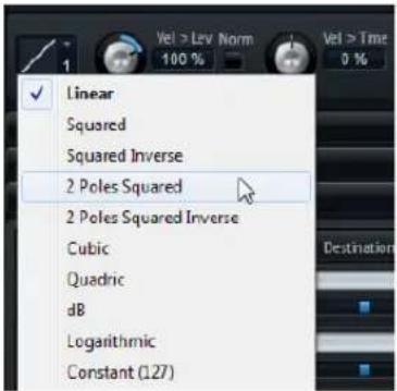
You can select the curve type to specify how the incoming velocity translates to the level of the envelope. The characteristic of each curve is displayed by a small icon.
Level Velocity (Vel>Lev)
Use this parameter to specify how the velocity affects the level of the envelope. The level depends on this parameter and how hard you hit a key. Positive values increase and negative values decrease the level of the envelope the harder you hit a key.
Norm
The Norm option allows you to normalize the velocity values that are used to control the envelope. This option is also available in the Filter section, see "Norm" on page 83.
Time Velocity (Vel>Time)
Use this parameter to adjust the influence of velocity on the times of the envelope. Positive values decrease the times for higher velocity values. Negative values increase the times for higher velocity values.
Segments
On the Segments pop-up menu, you can select which stages of the envelope are affected by the Time Velocity parameter.
Option Description
A The velocity affects the attack time only.
A+D The velocity affects all times until the sustain.
D The velocity affects all times until the sustain but without the attack.
A+R The velocity affects the attack and the release times.
All The velocity affects all times.
Key Follow and KeyF Rel
With Key Follow and KeyF Rel (Key Follow Release) you can scale the envelope times across the keyboard. Key Follow scales all times before the sustain node. KeyF Rel scales all times after the sustain node (which equals the release of the envelope). You can set a center key that is used as the central position for the Key Follow and KeyF Rel functions. The envelope times depend on the position where you play the keyboard and on the corresponding Key Follow setting. Positive values decrease the times for notes above and increase the times for notes below the center key; the envelope becomes faster the higher you play. Negative values increase the times for notes above and decrease the times for notes below the center key; the envelope becomes slower the higher you play.
Center Key
This parameter determines the MIDI note that is used as the central position for the Key Follow and KeyF Rel functions.
The LFO Section
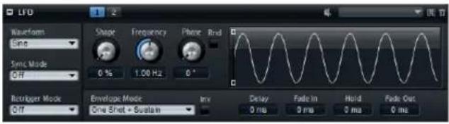
The synth and sample zones offer two polyphonic LFOs. Polyphonic means the LFOs are calculated per voice allowing for independent modulations with each triggered note. You can use this to create a richer sound, for example, with an independent pitch modulation per note. The LFOs can be assigned freely in the modulation matrix and they have an additional envelope that allows you to shape the modulation intensity over time.
You can also configure monophonic LFOs using a MIDI Module, see "Mono LFO" on page 147.
- To access the LFOs, click the corresponding button at the top of the LFO section.
LFO Waveform and Shape
Waveform selects the basic type of waveform. Shape changes the characteristic of the waveform.
Option Description
| Sine | This produces smooth modulation, suitable for vibrato or tremolo. Shape adds additional harmonics to the waveform. |
| Triangle This is similar to Sine. Shape continuously changes the triangle waveform to a trapezoid. | |
| Saw This produces a ramp cycle. Shape continuously changes the waveform from ramp down to triangle to ramp up. | |
| Pulse | This produces stepped modulation, where the modulation switches abruptly between two values. Shape continuously changes the ratio between the high and low state of the waveform. With Shape set to 50 %, a square wave is produced. |
| Ramp This is similar to the Saw waveform. Shape increasingly puts silence before the sawtooth ramp up begins. | |
| Log Shape continuously changes the logarithmic curvature from negative to positive. | |
Option Description
S & H 1 This produces randomly stepped modulation, where each step is different. Shape puts ramps between the steps and changes the S&H into a smooth random signal when fully turned right.
S & H 2 This is similar to S & H 1. The steps alternate between random high and low values. Shape puts ramps between the steps and changes the S & H into a smooth random signal when fully turned right.
Sync Mode
You can sync the LFO to the tempo of the host application. The behavior of the Frequency parameter changes with the selected option:
Option Description
Off Select this to adjust the speed of the modulation in Hertz.
Tempo + Retrig Select this to adjust the speed of the modulation in fractions of beats. You can also set dotted and triplet note values. The restart behavior of the LFO depends on the Retrigger Mode.
Tempo + Beat Select this to adjust the speed of the modulation in fractions of beats. You can also set dotted and triplet note values. The LFO restarts with the transport of the host and lines up to the beats of the song. The Retrigger setting is not taken into account.
Retrigger Mode
This defines whether the LFO is restarted when a note is triggered. The waveform restarts at the position you specify with the Phase parameter.
The polyphonic LFOs can switch between Retrigger On and Off: When it is off, the LFO runs freely, when set to On, the LFO starts with each triggered note.
Frequency
This controls the frequency of the modulation, that is the speed of the LFO. When Sync is activated, the frequency is set in fractions of beats.
Phase
This sets the initial phase of the waveform when the LFO is retriggered.
Rnd (Random)
When this is activated, each note starts with a randomized start phase. The Phase control is automatically disabled.
Delay
Delay determines the delay time between the moment you play a note and the moment the LFO comes into effect.
Fade In
Fade In determines how long the LFO takes to fade in after the note was triggered and the delay time has elapsed.
Hold
Hold determines the amount of time the LFO is running before the fade out begins.
Use the envelope modes "One Shot" or "Hold + Fade Out" to activate the Hold time. With all other envelope modes, the Hold time is omitted and acts as Sustain.
Fade Out
Fade Out determines how long the LFO takes to fade out after the hold time has elapsed or a note has been released.
Use the envelope modes "One Shot + Sustain" or "Sustain" to deactivate the fade out. This prevents changes of the modulation when the note has been released.
Inv (Invert Envelope)
When the Inv option is activated, the behavior of the LFO envelope is inverted. The LFO modulation starts at its maximum level and decreases to zero in the time specified by the Fade In. After the Hold time has elapsed, or when the key is released, the modulation increases to its maximum level in the time specified by the fade out.
Envelope Mode
Here, you can specify how the LFO envelope reacts to your playing on the keyboard. The One Shot modes do not react to note-off events. In addition, you can select whether the Hold and Fade Out segments act as sustain.
Option Description
| One Shot | Select this mode to play the envelope from start to end in the time specified by Delay, Fade In, Hold, and Fade Out. |
| One Shot + Sustain | This mode is similar to One Shot. The Delay and Fade In parameters are always applied when you play a note. The Hold and Fade Out parameters are not taken into account. Instead, they act as sustain. |
Option Description
| Hold +Fade Out | When you play a note, the Delay and Fade In parameters are applied. The envelope fades out after the time specified by the Hold parameter, or when a key is released. Releasing a key during the fade in starts the fade out from the current level. |
| Sustain +Fade Out | When you play a note, the Delay and Fade In parameters are applied. The Hold parameter acts as sustain. The fade out is applied when releasing the key. Releasing a key during the fade in starts the fade out from the current level. |
| Sustain When you play a note, the Delay and Fade In parameters are applied. Both the Hold and Fade Out parameters act as sustain. Releasing a key during the Fade In sustains the current level. This prevents a change in modulation when a key is released. | |
Graphical Envelope Editing
You can adjust the times of the envelope in the graphical editor by dragging nodes left or right.
- The first node adjusts the Delay time.
- The second node adjusts the Fade In time.
- The third node adjusts the Hold time.
- The fourth node adjusts the Fade Out time.
The Step Modulator Section
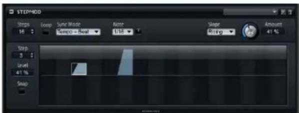
Synth and sample zones feature a polyphonic step modulator for creating rhythmic control sequences. The step modulator can be freely assigned in the modulation matrix. The sequence can have up to 32 steps.
At the top right of the Step Modulator section, you can load and save presets for the step modulator.
Editing Steps
To adjust the steps using the mouse, proceed as follows:
- To set the level of a step, click in the graphical editor.
-
To change the value of a single step, drag it up/down.
-
To adjust all steps at once, [Shift]-drag a step.
- To reset a step to a level of 0%, [Ctrl]/[Command]-click the step.
- To reset all steps, [Shift]-[Ctrl]/[Command]-click in the graphical editor.
- To draw a ramp with steps, [Alt]/[Option]-click and draw a line.
- To draw symmetric ramps, [Shift]-[Alt]/[Option]-click and draw a line.
- You can also enter a value directly in the value field for the step.
- To increment or decrement the selected step, use the up and down arrow keys.
By default, the increment or decrement is in steps of 1%. Hold [Shift] to increment or decrement the selected step in steps of 0.1%.
Steps
Here you set the number of steps the sequence plays.
Sync Mode
You can synchronize the steps to the tempo of the host application by setting a note value. Alternatively, you can specify a frequency at which the sequence repeats.
Whether you can set a note value or a frequency depends on the option you select here:
Option Description
| Off Select this to adjust the speed at which the sequence repeats (in Hertz). Whether the sequence restarts when you play a note depends on the Retrigger mode. | |
| Tempo + Retrig | Select this to adjust the length of the steps in fractions of beats. The speed of the modulation depends on the number of steps, the note value and the tempo you set in your host application. Activate the T option to use triplet note values. Whether the sequence restarts when you play a note depends on the selected Retrigger mode. |
| Tempo + Beat | As above, but the sequence restarts with the transport of the host and lines up to the beats of the project. The Retrigger setting is not taken into account. |
Frequency
When Sync mode is set to Off, this controls the speed at which the sequence is repeated.
Note
When the Sync mode is set to one of the Tempo settings, this adjusts the length of the steps in fractions of beats. You can also select dotted and triplet values.
Triplets
Activate the "T" option to use triplet note values.
Retrigger Mode
Here, you can determine whether the sequence restarts when you play a note. The Retrigger Mode parameter is only available when Sync mode is set to Off or "Tempo + Retrig". The following parameters are available:
Option Description
| Off | The sequence is not restarted. Instead, it resumes play-back at the position at which you released the key. |
First Note The sequence restarts when a note is triggered and no other notes are held.
Each Note The sequence restarts each time a note is triggered.
Slope
Depending on the setting you select here, the step modulator jumps from step to step or creates ramps between the steps. The following settings are available:
Option Description
None This setting produces hard steps.
Rising Ramps are created only for rising edges.
Falling Ramps are created only for falling edges.
All Ramps are created for all edges.
Amount
When Slope is set to Rising, Falling or All, the Amount parameter determines the time of the ramp between two steps. The higher the setting, the smoother the transitions between steps.
Step
Use this to select a certain step.
Level
This shows the level of the selected step.
Snap
When Snap is activated, the level of each step can only be adjusted in quantized steps of 1/12th.
Producing Modulations in Steps of Semitones
Proceed as follows:
- Activate the Snap option.
- In the modulation matrix, assign the Step Modulator to Pitch.
- Set the Modulation Depth to +12.
Now, the levels of the steps represent semitone intervals. - Go back to the step modulator and adjust each step to the interval that you want to use.
The Modulation Matrix Section
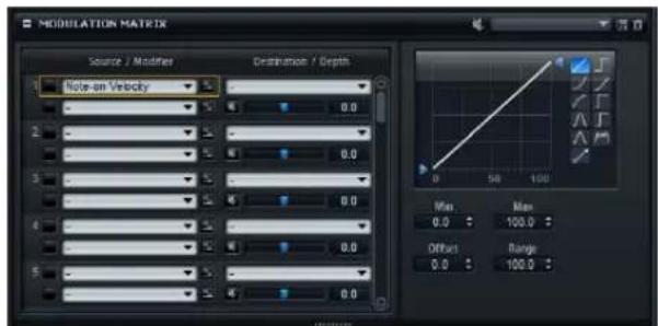
The concept of controlling one parameter by another is called modulation. The Modulation Matrix section of synth and sample zones gives you access to additional modulations of the zone.
Assigning modulations means to interconnect modulation sources, such as LFOs and envelopes, with modulation destinations like pitch, cutoff, amplitude, etc. The modulation matrix offers you up to 32 freely assignable modulations, each with a source, a modifier and a destination with adjustable depth. All modulation sources and destinations can be assigned several times. The polarity of each source can be switched between unipolar and bipolar. An additional modifier and user-definable curves and ranges give you further control over the modulation.
The modulation matrix is divided into two sections. On the left, the modulation rows are displayed. Here, you can assign modulation sources to destinations and adjust the modulation depth. The section on the right contains settings for the curve and range editor, where you can make further settings for the selected modulation source.
Using the Modulation Rows
The modulation rows allow you to interconnect modulation sources with modulation destinations and to adjust the modulation depth.
- The parameters for setting up a modulation can be accessed via 32 rows. Each row is identified by a number.
- You can select modulation sources on the Source 1 pop-up menu at the top left of each row.
- The Source 2 pop-up menu below the Source 1 pop-up menu for each row allows you to select a second modulation source that controls the intensity of the first source or a modifier that alters the modulation signal of the first source.
- To switch the polarity of a source between unipolar and bipolar, click the button to the right of the corresponding source.
- To select the modulation destination, use the pop-up menu to the right.
- Use the horizontal fader below the destination to adjust the modulation depth. Usually, the modulation depth is adjusted in percent. If you select pitch as modulation destination, the modulation depth is adjusted in semitones.
- Click the Bypass button in front of the depth control to switch off the modulation temporarily.
Managing Modulation Rows
To copy a modulation row, proceed as follows:
- On the context menu for the source row, select "Copy Modulation Row".
To move a modulation row, select "Cut Modulation Row" for the source row.
- On the context menu for the target row, select "Paste Modulation Row".
- To insert an empty row, select "Insert Modulation Row" from the context menu.
- To remove a modulation row, select "Remove Modulation Row" from the context menu.
An empty modulation row is appended to the list to keep a constant number of 32 rows.
⇒ You can copy modulation rows across different programs or even between different instances of HALion.
Unipolar vs. Bipolar Sources
The polarity of a modulation source specifies the value range it produces.
- Unipolar sources modulate between 0 and +1.
- Bipolar sources modulate between -1 and +1.
By default, some sources are unipolar and others are bipolar. However, you can change the polarity of a modulation source at any time.
- To change the polarity of a source, click the button to the right of the corresponding source.
Using the Curve and Range Editor
You can set up a curve and range for each modulation source.
- The curve and range editor displays the settings of the selected source. To adjust the settings of a different source, click the button to the left of the source you want to edit.
- The curve editor allows you to change the characteristic of a modulation. The displayed curve is superimposed on the modulation source.
This way, you can change the modulation from linear to exponential or logarithmic, for example.
- By setting the minimum and maximum values, the modulation stays within the specified range only. In addition, you can specify an offset and a range for the modulation. For example, with an offset and range of +50% , only the second half of the displayed curve is superimposed on the modulation.
The curve editor offers different presets that you can select from the pop-up menu above the curve. To set up your own curve, select the Custom preset.
- Double-click in the editor to insert a new node. Double-click on a node to delete it.
- Drag the nodes to new positions to adjust the basic shape of the curve.
- Drag the lines between the nodes up or down to change the curvature.
Setting Up a Modulation
Proceed as follows:
- Select the zone that you want to adjust.
- Open the Modulation Matrix section.
- In one of the modulation rows, select a modulation source and destination (for example LFO1 as source and Pitch as destination).
- Use the horizontal fader below the destination to adjust the modulation depth.
- Play a few notes to hear the modulation.
- You can select a modifier or change the polarity of the source.
For example, from the "Source 2" pop-up menu, select Pitch Bend as the modifier and set its polarity to unipolar.
-
Play a few notes to hear the modulation and use the pitchbend wheel.
-
Finally, use the curve and range editor to limit the modulation range or to adjust the characteristic of the modulation.
Modulation Sources
The modulation sources are available from the Source and Modifier pop-up menus. HALion offers you the following modulation sources:
Option Description
| LFO P1 The first LFO of the zone, which produces cyclic modulation signals. | |
| LFO P2 The second LFO of the zone, which produces cyclic modulation signals. | |
| Amp Envelope | The amplifier envelope of the zone (unipolar). The shape of the envelope equals the modulation signal. |
| Filter Envelope | The filter envelope of the zone (unipolar). The shape of the envelope equals the modulation signal. |
| Pitch Envelope | The pitch envelope of the zone (bipolar). The shape of the envelope equals the modulation signal. |
| User Envelope | The user envelope of the zone (bipolar). The shape of the envelope equals the modulation signal. |
| Step | The step modulator of the zone (bipolar). This produces cyclic, rhythmically stepped modulation signals. |
| Modulator | |
| Glide | The glide signal of the source (unipolar). |
Option Description
| Key Follow | This produces an exponential modulation signal derived from the MIDI note number. Exponential means this source works with destinations such as Pitch or Cutoff.Key follow is bipolar. |
| Note-on Vel Note-on velocity (how fast you hit a key) can be used as a modulation signal. Note-on Vel is unipolar. | |
| Note-on Vel Squared | The squared version of Note-on Vel. Squared means you have to press the key harder to produce higher modulation values. |
| Note-on Vel Normalized | The note-on velocity is normalized via the velocity range of the corresponding zone. At the lowest velocity of the zone the modulation is 0, at the highest velocity it is 1. |
| Note-off Vel | Note-off velocity (how fast you released a key) can be used as a modulation signal. Note-off Vel is unipolar.While most of the MIDI keyboards cannot send note-off velocity messages, most sequencer software is able to produce such messages. |
| Pitchbend The position of the pitchbend wheel can be used as a modulation signal. Pitchbend is bipolar. | |
| Modulation Wheel | The position of the modulation wheel can be used as a modulation signal. Modulation Wheel is unipolar. |
| Aftertouch Aftertouch (how hard you keep a key pressed after you hit it) can be used as a modulation signal. Aftertouch is unipolar. Some MIDI keyboards cannot send aftertouch messages. However, most sequencer software is able to produce such messages. | |
| MIDI Controller Any of the 127 available MIDI controllers can be used as a modulation signal. You can select the MIDI controller from the corresponding submenu. | |
| Quick Control | The quick controls of the program or layer the zone belongs to can be used as a modulation signal. You can select the quick control from the corresponding submenu. |
| Note Expression | The eight note expression parameters of the program can be used as modulation signals for the zone. You can select the note expression parameter from the corresponding submenu. |
| Noise Produces a random modulation signal. Noise is bipolar. | |
| Output | The audio output of the zone can be used as a modulation signal. Output is unipolar. |
| Bus 1-16 | Modulations that have been sent to one of the sixteen busses can be used as sources again. This way, you can combine several modulations to produce more complex signals. Select the corresponding modulation bus to assign it as source. |
Modulation Destinations
Depending on the selected type of zone, the available modulation destinations vary. HALion offers you the following modulation destinations:
Option Description
| Pitch Modulates the pitch of the zone. For example, assign one of the LFOs to create a vibrato effect. When Pitch is selected, the modulation depth adjusts in semitones (-60 to +60). | |
| Cutoff | Modulates the filter cutoff of the zone. For example, assign the step modulator to create rhythmic patterns in the spectral timbre. |
| Resonance Modulates the filter resonance of the zone. Resonance changes the character of the filter. For example, assign velocity to resonance to accent the filter the harder you hit a key. | |
| Morph X | Modulates the x-axis of the filter in Morph XY mode. Use this to morph between the filter shapes AD and BC. |
| Morph Y Modulates the y-axis of the filter in Morph 2, Morph 4, or Morph XY mode. For example, use this to morph between the filter shapes AB and DC. | |
| Cutoff Offset Modulates the cutoff offset of the second filter in serial or parallel mode. For example, assign the modulation wheel to lower or raise the cutoff of the second filter while you play. | |
| Resonance Offset | Modulates the resonance offset of the second filter in serial or parallel mode. For example, assign the modulation wheel to lower or raise the resonance of the second filter while you play. |
| Pan Modulates the position of the zone in the panorama. | |
| Level | This modulation adds to the level setting of the zone. It is ideal for effects such as tremolo. |
| Volume 1 | This modulates the gain of the zone. The volume modulation multiplies with the level of the zone. It is ideal for crossfades between zones. |
| Volume 2 As Volume 1. Volume 1 is multiplied with volume 2. This way, you can build more complex modulations. For example, use Volume 1 for crossfading between zones and Volume 2 for fading them in or out. | |
| LFO1 Frequency | Modulates the speed of LFO1. For example, assign Aftertouch to control the speed of a vibrato effect while you play. |
| LFO1 Shape Modulates the waveform of LFO1. For example, assign Key Follow to vary the waveform with the playing position on the keyboard. | |
| LFO2 Frequency | Same as LFO1 Freq, but for LFO2. |
| LFO2 Shape Same as LFO1 Shape, but for LFO2. | |
| Step Mod Frequency | Modulates the speed of the step modulator. For example, assign an LFO to increase or decrease the speed cyclically. |
Option Description
| Step Mod Slope | Modulates the shape of the edges of the step modulator (the Slope parameter has to be active). For example, assign the modulation wheel to blend from hard to smooth edges. |
| Amp Env Attack Time | Modulates the time of the amplitude envelope attack (the first segment of the envelope). The attack time cannot be modulated continuously. The time is updated only when the segment starts. |
| Amp Env Decay Time | Modulates the time of the amplitude envelope decay (all segments after the attack and before the sustain). The decay time cannot be modulated continuously. The time is updated only when the segment starts. |
| Amp Env Sustain Level | Modulates the level of the amplitude envelope sustain. The sustain level cannot be modulated continuously. The level is updated only when the segment starts. |
| Amp Env Release Time | Modulates the time of the amplitude envelope release (all segments after the sustain). The release time cannot be modulated continuously. The time is updated only when the segment starts. |
| Filter Env Attack Time | Modulates the time of the filter envelope attack (the first segment of the envelope). The attack time cannot be modulated continuously. The time is updated only when the segment starts. |
| Filter Env Decay Time | Modulates the time of the filter envelope decay (all segments after the attack and before the sustain). The decay time cannot be modulated continuously. The time is updated only when the segment starts. |
| Filter Env Sustain Level | Modulates the level of the filter envelope sustain. The sustain level cannot be modulated continuously. The level is updated only when the segment starts. |
| Filter Env Release Time | Modulates the time of the filter envelope release (all segments after the sustain). The release time cannot be modulated continuously. The time is updated only when the segment starts. |
| Pitch Env Attack Time | Modulates the time of the pitch envelope attack (the first segment of the envelope). The attack time cannot be modulated continuously. The time is updated only when the segment starts. |
| Pitch Env Decay Time | Modulates the time of the pitch envelope decay (all segments after the attack and before the sustain). The decay time cannot be modulated continuously. The time is updated only when the segment starts. |
| Pitch Env Sustain Level | Modulates the level of the pitch envelope sustain. The sustain level cannot be modulated continuously. The level is updated only when the segment starts. |
| Pitch Env Release Time | Modulates the time of the pitch envelope release (all segments after the sustain). The release time cannot be modulated continuously. The time is updated only when the segment starts. |
| User Env Attack Time | Modulates the time of the user envelope attack (the first segment of the envelope). The attack time cannot be modulated continuously. The time is updated only when the segment starts. |
Option Description
| User Env Decay Time | Modulates the time of the user envelope decay (all segments after the attack and before the sustain). The decay time cannot be modulated continuously. The time is updated only when the segment starts. |
| User Env Sustain Level | Modulates the level of the user envelope sustain. The sustain level cannot be modulated continuously. The level is updated only when the segment starts. |
| User Env Release Time | Modulates the time of the user envelope release (all segments after the sustain). The release time cannot be modulated continuously. The time is updated only when the segment starts. |
| Bus 1-16 | You can send any modulation to one of the sixteen buses, for example, to produce more complex modulation signals. Select the bus you want to send the signals to as a destination. To use the modulation that was sent to a bus, assign the corresponding bus as a modulation source. |
The following destination is only available for sample zones:
| Option Description | |
| Sample Start | Modulates the start position of the sample play-back. For example, assign note-on velocity to play back more of the attack of a sample the harder you hit a key. The sample start cannot be modulated continuously. The parameter is updated only when you hit a key. |
The following destinations are only available for synth zones:
| Option Description | |
| Osc1/2/3 Pitch | Modulates the pitch of the corresponding oscillator. For example, assign one of the LFOs to detune the oscillator cyclically. |
| Osc1/2/3 Level | Modulates the volume of the corresponding oscillator. For example, assign the modulation wheel to fade the oscillator in and out while you play. |
| Osc1/2/3 Waveform | Modulates the shape and character of the corresponding oscillator. For example, assign one of the envelopes to change the character of the oscillator over time. |
| Sub Osc Level | Modulates the volume of the sub oscillator. For example, assign the modulation wheel to fade in the oscillator while you play. |
| Ring Mod Level | Modulates the volume of the ring modulation effect. For example, assign the modulation wheel to fade in the ring modulation while you play. |
| Noise Gen Level | Modulates the volume of the noise generator. For example, assign the modulation wheel to fade in the noise generator while you play. |
Sample & Hold
The Sample & Hold modifier takes a sample of the modulation source whenever it receives a trigger signal. It holds the sampled value until it receives a new trigger. This way, you can quantize a continuous modulation signal. The Sample & Hold modifier offers the following options:
Option Description
| Trigger on Note On | Select this to trigger the Sample & Hold modifier manually. Each time you hit a key, the modifier takes a sample. |
| Trigger on LFO1 | Select this for periodic triggering of the Sample & Hold modifier. It takes a sample each time the waveform of LFO1 crosses the zero line upwards. |
| Trigger on LFO2 | Select this for periodic triggering of the Sample & Hold modifier. It takes a sample each time the waveform of LFO2 crosses the zero line upwards. |
| Trigger on Modulation Wheel | Select this to trigger the Sample & Hold modifier manually. It takes a sample each time the modulation wheel passes the center position. |
| Trigger on Sustain | Select this to trigger the Sample & Hold modifier manually. Each time you press the sustain pedal, the Sample & Hold modifier takes a sample. |
| Sample until Release | Select this to trigger the Sample & Hold modifier through releasing a key. It constantly takes samples and holds the last sample when receiving a note-off. |
Using Global MIDI Controllers
HALion features eight global MIDI controllers ("Contr. A - Contr. H"), which can be used as placeholders in the modulation matrix. With these controllers, you can remap specific MIDI controllers to the placeholder controllers, for example, from the CC Mapper. This allows you to use the global controller in several places and set up the assignment only once.
Mapping Zones
Introduction
In HALion, you can edit the sample mapping manually in the Mapping editor. The Mapping functions are based on information like key range, root key, and velocity range.
The Mapping Editor
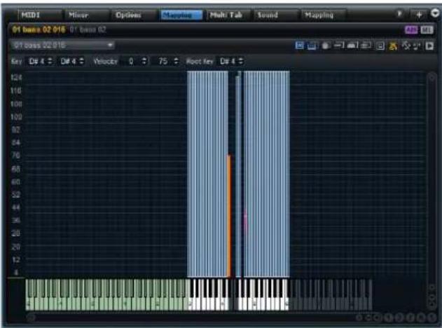
The Mapping editor allows you to view and edit the distribution of zones inside a program. All zones are mapped to the key range on the horizontal axis and the velocity range on the vertical axis. In the upper area, you have access to mapping ranges and sample parameters for the selected zone.
Zones are displayed as boxes. Selected zones are shown with a red border, and the focused zone with an orange border. Overlaying zones are semi transparent, so that overlapping areas can easily be recognized.
When playing notes on a MIDI keyboard, the Mapping editor shows you which note you play on the Mapping editor keyboard. Furthermore, you can see the current velocity in the velocity scale on the left.
The Toolbar
The toolbar at the top of the window shows the name of the focused zone and a number of editing options for the mapping.

The Zone Range Section
Below the toolbar, the zone range section is located. Here you can set the values for Low and High Key, Low and High Velocity, Root Key, Tune, and Gain of a zone. The Tune and Gain parameters are only available for sample zones.
The Mapping Editor Keyboard
The Mapping editor keyboard allows you to see with which keys a zone can be triggered. It can also be used to trigger notes. Depending on the vertical position at which you click the key, it produces a lower or higher velocity.
The context menu for a key contains submenus that show information on pitch and velocity as well as the zones that are mapped to a key.
→ Keys with no zones assigned to them are grayed out.
Testing the Sample Mapping
- [Ctrl]/[Command]-click a key on the Mapping editor keyboard and keep the mouse button pressed. HALion plays this key and all following keys at the same velocity, for as long as you press the mouse button.
- Hold down [Ctrl]/[Command]-[Alt]/[Option] and click a key to play each zone ten times, at increasing velocities from 1 to 127.
The Velocity Scale
The velocity scale on the left provides an orientation when adjusting the velocity range of a zone. In the background of the scale, a meter indicates the incoming velocity value. After each note, the meter automatically falls back to zero and leaves a marker on the last velocity value.
Setting the Focus in a Multi-Selection
When multiple zones are selected, you can click on a zone to set the focus. Alternatively, you can use the Focused Zone pop-up menu on the toolbar to select a different zone.
Zooming and Scrolling
The Mapping editor can zoom and scroll in two dimensions: keyboard and velocity.
- To zoom in or out, click the "+" or "-" button on the scrollbars. Once you have zoomed in, you can use the scrollbar to move to a specific velocity or keyboard area.
- To zoom in or out, press [H] or [G] on the computer keyboard.
- To zoom in on a specific zone, double-click it. To zoom out, double-click again.
- To zoom in on an area where two or more zones are overlapping, double-click the area. To zoom out, double-click again.
- To zoom to the selection, activate the S button next to the scrollbar.
- To zoom out completely or return to the last zoom state, click the A button next to the scrollbar.
Automatic Scrolling to a Tree Selection
When “Scroll Position follows Tree Selection” is activated on the toolbar and you select a zone in the Program Tree, the Mapping editor automatically scrolls the view to keep the selection in the center. This works on both the keyboard and the velocity axes.
Zoom Snapshots
Zoom Snapshots save the current zoom state in the Mapping editor. For example, by saving a snapshot for the lower and a snapshot for the upper range of the keyboard, you can switch between editing the two areas.
The snapshot handling is the same as for envelopes, see "Envelope Zoom Snapshots" on page 85.
Selecting Zones
- Click a zone to select it.
- [Ctrl]/[Command]-click to select several zones.
- Hold down [Ctrl]/[Command] and draw a selection rectangle covering the zones that you want to select.
- Press [Ctrl]/[Command]-[A] to select all zones.
- Click on the velocity scale to select all zones that belong to a certain velocity.
Moving Zones
Selected zones can be moved in the Mapping editor.
- Click in the middle of one of the zones and drag to move all the zones together.
To limit the movement to the vertical or horizontal direction, start dragging the zone in one direction and press [Ctrl]/[Command] or [Alt]/[Option], respectively.
When you move sample zones horizontally, they are transposed. To make moved samples play back at the right pitch again you have to adapt the Root Key setting or activate the "Move Root Key with Zones" button on the toolbar first.
Move Lock
By clicking the Move Lock button on the toolbar, you can prevent accidental moving or resizing of zones.
Setting Key and Velocity Range
Graphically
To set the key and velocity ranges, move your mouse to one of the borders of a zone, so that the mouse pointer changes to a double arrow, and drag. If you drag the left border, you set the lowest key for the key range, for example.
When you select multiple zones and drag the border of adjoining zones that are part of the selection, you can adjust the low and high values of the corresponding zones simultaneously.
Numerically
You can also set the key and velocity range values using the value fields at the top of the window.
When multiple zones are selected, only the values of the focused zone are displayed in the edit fields. However, changing the values affects all selected zones. Like in the Sound editor for a zone, you can choose between absolute and relative editing, see "Absolute and Relative Editing" on page 75.
Muting and Soloing Zones
You can mute and solo zones in the Mapping editor using the context menu.
Showing and Hiding Zones
You can show and hide zones using the Visibility context menu options.
Auto Visibility
The Auto Visibility option on the Visibility submenu allows you to control the visibility of zones inside the Mapping editor. When it is activated, only the selected zone and the other zones that are part of the same layer are shown.
Fading and Crossfading Zones
Zones in HALion can partially or totally overlap. Fades can be created in the horizontal (key) and the vertical (velocity) direction. This allows you to successively add certain sound components over the key or the velocity range.
To create fades or crossfades, proceed as follows:
- Select the zones that you want to fade or crossfade.
- Open the context menu, select the Crossfades submenu, and choose "Enable Crossfades on Keyboard Axis", or "Enable Crossfade on Velocity Axis", or both. HALion displays the fade handles.
- Drag the handles to adjust the fade ranges. Faded regions are shown in green.
Curve Shape
By default, the fade curve is exponential, but you can change the curvature by dragging the curve up and down. The maximum curve setting represents an equal power curve. This is useful for velocity crossfades.
Auto Crossfades
The Crossfade option on the toolbar can be set to Auto (the icon turns blue). In this mode, the crossfade range is automatically adjusted when you move overlapping zones.
Symmetric Crossfades
You can create symmetric crossfades for zones that have an identical key range and an adjacent velocity range.
Proceed as follows:
-
Select the two zones, open the context menu and on the Crossfades submenu, select "Enable Crossfade on Velocity Axis".
The crossfade handles are displayed. -
On the toolbar of the Mapping editor, set the Cross-fade option to Symmetric.
The icon turns yellow.
- Drag the handles to set up the crossfade.
Setting the Root Key
The root key determines the original pitch of a zone. In other words, it defines the key on which the zone is played without being transposed. Samples can contain root key information embedded in the sample file. When they are loaded, they are automatically mapped to the corresponding keys.
The sample collections included with HALion contain both multi-sampled instrument programs and single-shot sample programs. The former contains samples of a specific instrument (usually containing only one sample zone per key on the keyboard). The latter contains different sample zones that are mapped across the keyboard, without any relationship between key and pitch. For multi-sampled instrument programs, there is no need to change the root key settings, but for single-shot sample programs, you might want to move sample zones.
If you have moved sample zones in the Mapping editor, you can make them play back at the original pitch by setting the root key.
You have the following possibilities:
- Directly enter the value in the Root Key value field.
- Hold [Alt]/[Option] and click the corresponding key on the Mapping editor keyboard.
When you move a sample zone, you can make the root key move with the zone by holding [Ctrl]/[Command]-[Alt]/[Option] while dragging or by activating "Move Root Key with Zones" on the toolbar.
Triggering Zones
You can trigger zones in the Mapping editor. To activate trigger mode, click the Trigger Zones button on the toolbar.
Importing Samples Using Drag and Drop
To import a single sample to a specific key (or key range) in the Mapping editor, proceed as follows:
- Drag a sample into the Mapping section or onto the keyboard.
An outline representing the sample appears.
- Without dropping the sample, move the mouse pointer up and down.
The horizontal position of the mouse pointer determines the lowest key of the key range, and the vertical position of the mouse pointer determines the key zone range.
- Drop the sample to insert it.
To import several samples this way, proceed as follows:
-
Select the samples that you want to import.
-
Drag the samples to the key on the Mapping editor keyboard where you want the first selected sample to be placed.
-
Without dropping the samples, move the mouse up and down.
The samples are mapped chromatically. Moving the mouse up or down resizes the key range for each zone.
- Release the mouse button to insert the samples.
- If you move the mouse pointer to the bottom of the Mapping editor, the samples are distributed to different velocities rather than key ranges.
The first selected sample gets the highest velocity and the last selected the lowest velocity.
- If you press [Ctrl]/[Command] and move the mouse pointer to the bottom of the mapping view, the samples are layered on the keys that you drop them on.
- If you press [Ctrl]/[Command] and point at a white key, the samples are mapped to the consecutive white keys only, and the key range cannot be extended.
Pointing to a black key maps the samples to black keys instead.
If you drag samples from a separate browser window, the selection order determines how the samples are mapped, with the first selected sample being mapped to the first key.
Mapping Zones
To set up or change the mapping of zones in the Mapping editor, proceed as follows:
-
In the Mapping editor or the Program Tree, select the zones for which you want to adjust the mapping.
-
On the context menu, open the Mapping submenu, and select one of the functions.
The following mapping functions are available:
Option Description
| Root Key Only Each zone is mapped to its root key only. | |
| Root Key Fill Centered | The zones expand to the left and the right of the root key to fill empty spaces. |
| Root Key Fill Up | The zones expand upwards from the root key to fill empty spaces. |
| Root Key Fill Down | The zones expand downwards from the root key to fill empty spaces. |
| Layered on Root Key | The zones are layered on the root key, equally spaced from the lowest to the highest velocity. |
| Layered on Key Range | Zones that have exactly the same key range are layered equally spaced from the lowest to the highest velocity. |
| Chromatic from Last Key | Starting with the highlighted key of the Mapping editor keyboard, the zones are mapped chromatically to the white and black keys in ascending order. The root keys are set to match the corresponding key. |
| White Keys from Last Key | Starting with the highlighted key of the Mapping editor keyboard, the zones are mapped to the white keys in ascending order. The root keys are set to match the corresponding key. |
| Black Keys from Last Key | Starting with the highlighted key of the Mapping editor keyboard, the zones are mapped to the black keys in ascending order. The root keys are set to match the corresponding key. |
| Layered on Last Key | On the highlighted key of the Mapping editor keyboard, the zones are layered equally spaced from lowest to highest velocity. The root keys are set to match the highlighted key. |
| Stacked on Last Key | At the highlighted key of the Mapping editor keyboard, the zones are stacked on each other. The root keys are set to match the highlighted key. |
| Key Text in Sample Name | The zones are mapped to the key that is extracted from the sample file name. The function searches for the name of the key in text form, e.g., C#3. The mapping and root key are set to that key. |
| Key Number in Sample Name | The zones are mapped to the MIDI note number that is extracted from the sample file name. The function searches for a number, e.g., 61. The mapping and root key are set to that key. |
| Velocity in Layer Name | The zones are mapped to the velocity range that is extracted from the layer name. |
Option Description
| Velocity in Sample Name | The zones are mapped to the velocity range that is extracted from the sample file name. |
| Velocity in Sample Folder | The zones are mapped to the velocity range that is extracted from the name of the sample folder. |
| Ranges in Sample File | The zones are mapped to the key and velocity ranges that are stored in the sample file's header chunk. If the header chunk of the sample file contains no information, a message informs you that the samples could not be mapped. |
Only values between 0 and 127 can be extracted as MIDI note numbers or velocity ranges. The smaller number is used as the lower limit and the higher number as the upper limit, for example "Sample_Name_Range_90-127".
Filling Gaps between Zones
Proceed as follows:
- In the Mapping editor or Program Tree, select the zones that you want to adjust.
- Right-click the zones, open the Fill Gaps submenu, and select one of the functions.
The following Fill Gaps functions are available:
Option Description
| Pitch Only Fills any gaps between the selected zones on the keyboard axis. | |
| Velocity Only Fills any gaps between the selected zones on the velocity axis. | |
| Pitch & Velocity Gaps on the keyboard axis are filled first. Then the remaining gaps on the velocity axis are filled. | |
| Velocity & Pitch | Gaps on the velocity axis are filled first. Then the remaining gaps on the keyboard axis are filled. |
Setting the Root Key
- To adjust the root keys of the selected zones without changing their key or velocity ranges, right-click one of the zones, open the "Set Root Key" submenu and select a function.
The following options are available:
Option Description
| Center of Zone | Sets the root key to the center of the zone. If the zone has no center because it has an even number of keys, the root key is set to the key in the center that is closest to the previous root key. |
Option Description
| High Key of Zone Sets the root key to the High Key of the zone. | |
| Low Key of Zone Sets the root key to the Low Key of the zone. | |
| Key Text in Sample Name | Sets the root key to the key that is extracted from the sample file name. The function searches for the name of the key in text form. |
| Key Number in Sample Name | Sets the root key to the MIDI note number that is extracted from the sample file name. The function searches for a number. |
| Root Key in Sample File | Sets the root key to the key that is stored in the header chunk of the sample file. |
Selecting Zones with the Mapping Editor Keyboard
You can select zones using the Mapping editor keyboard or an external MIDI keyboard.
To select zones via the keyboard, activate the "Enable MIDI Mapping Selection Options" function on the toolbar and select one of the following options:
Option Description
| Select Zones with the Mapping Editor Keyboard | Activate this option to select zones by clicking on the Mapping editor keyboard. |
| Select Zones via MIDI | Activate this option to select zones by playing on an external MIDI keyboard. |
| Select Zones depending on Velocity | When this option is activated, the incoming velocity is taken into account. Only zones that match the incoming velocity are selected. |
| Select Zones using a MIDI Controller to set the Velocity | When this option is activated, the velocity from the keyboard is replaced by the controller values sent by the selected controller. Right-click the icon to select another controller or use the Learn function on the pop-up menu. |
| Select all Zones between the last two played notes | Any zones between the last two triggered zones are selected.You can extend the selection by playing a key and holding it. Any additional keys that you play add the corresponding zones to the selection.If you play a chord, any zones between the lowest and the highest key are selected. |
Editing Samples in the Sample Editor
Introduction
The Sample editor allows you to view and manipulate samples. In HALion, samples are associated with sample zones. When a sample zone is selected, the Sample editor shows the selected sample. The Sample editor is divided into different sections. The main space shows the waveform display and the lower section gives you access to all relevant sample parameters.
Overview
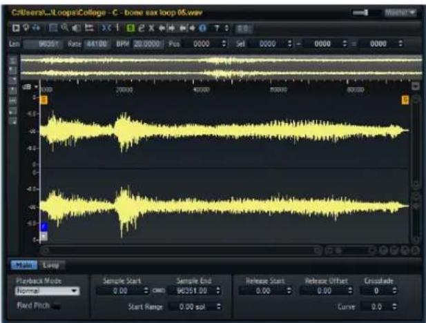
The Toolbar

The toolbar contains the tools to edit the sample and loop markers.
The Info Line

The info line shows information about the sample (length, sample rate and tempo, etc). Furthermore, you can set the locator position and the start, end, and length of the selection.
The Overview Line
The overview line shows the whole sample. The section visible in the main waveform display is indicated by a rectangle on the overview line and the current selection range is shown in orange.
You can move the rectangle in the overview line to view other sections of the sample. Click in the lower half of the rectangle and drag to the left or right to move it.
You can resize the rectangle by dragging its left or right border.
You can define a new viewing area by clicking in the upper half of the overview and dragging a rectangle with the mouse.
The Ruler
The Sample editor ruler is located between the overview line and the waveform display. It shows the timeline in the specified display format.
- To select the format, click the arrow button to the right of the ruler and select an option from the pop-up menu. You can choose to display hours, minutes, seconds, and milliseconds, or samples, or bars and beats.
The Waveform Display and the Level Scale
The waveform display shows the waveform image of the sample. To the left of the waveform display, a level scale is shown, indicating the amplitude of the audio.
- To select whether the level is shown as a percentage or in dB, click the level scale label (dB or %), and select an option from the pop-up menu.
- To display the half level axes, right-click in the Sample editor and select the corresponding option on the context menu.
The Parameter Section
The parameter section contains sample and sample zone parameters. It has two tabs: Main and Loop.

The Main Tab
The Main tab contains the zone parameters, and the marker settings for Sample Start, Sample End, Start Range, as well as the parameters for the Release marker.
Playback Mode
The Playback Mode options are described in the section "Playback Mode" on page 80.
Fixed Pitch
This option is described in the section "Fixed Pitch" on page 81.
The Loop Tab
The Loop tab contains the loop settings, see "Creating Loops" on page 108.
General Operations
Zooming
- You can use the horizontal and vertical zoom sliders in the left lower corner of the editor to zoom in/out on the time and the level axis.
- You can press [G] and [H] to zoom in/out on the locator position.
- You can click and drag the ruler to zoom in/out on the position you have clicked.
-
Three buttons to the right of the zoom slider allow you to zoom to specific markers or ranges: Zoom to Start, Zoom to End and Zoom to Full Range.
Depending on your work situation, these options refer to the sample, the selection, or a loop. Clicking several times increases the zoom level on the same marker position. -
You can zoom by resizing the rectangle in the overview line.
- You can use the options on the Zoom submenu of the Sample editor context menu.
- You can toggle between full zoom and the previously set zoom level by clicking the A button in the lower right corner of the Sample editor.
View Range
When changing from one sample to another, you have several options how to set up the visible range for the newly selected sample zone.
The following options are available on the Sample editor context menu:
Option Description
| Auto Follows the visible view range of the previous sample. This is the default setting. | |
| Last Each zone stores the visible range individually. When you select a zone again, its view range is restored. | |
| Full Shows the full sample. | |
| Sample Start Shows the sample start marker with the current zoom factor. | |
| Sample Start Range | Shows the sample start range marker with the current zoom factor. |
| Sample End Shows the sample end marker with the current zoom factor. | |
| Sustain Loop | Shows the sustain loop with the current zoom factor. |
| Sustain Loop Start | Shows the sustain loop start marker with the current zoom factor. |
| Sustain Loop End | Shows the sustain loop end marker with the current zoom factor. |
| Release Loop Shows the release loop with the current zoom factor. | |
| Release Loop Start | Shows the release loop start marker with the current zoom factor. |
| Release Loop End | Shows the release loop end marker with the current zoom factor. |
⇒ If the visible range cannot be set to the specified loop marker or range because the sample does not contain the required loop, it is set to the last stored settings for that zone. If no such settings are found, the full sample is displayed.
Auditioning Samples
You can play back the sample using the audition icon (Play Sample) on the toolbar.
The following applies:
- If you have not made a selection, the whole sample is played back.
- If you have made a selection, this selection is played back.
- If the Edit Loop function is activated, playback continues repeatedly until you deactivate the audition function.
You can specify the playback start position by clicking in the timeline.
Using the Edit Loop Function

You can play back a looped selection when the Edit Loop icon is activated on the toolbar. This allows you to check the crossfade section of a long loop without having to wait until the loop has finished, for example.
Using the Play Tool

If you click somewhere in the waveform display with the Play tool and keep the mouse button pressed, the sample is played back from the position at which you clicked until you release the mouse button.
Scrubbing

The Scrub tool allows you to locate positions in the audio by playing back, forwards or backwards, at any speed:
- Select the Scrub tool.
- Click in the waveform display and keep the mouse button pressed.
- Drag to the left or right.
The audio is played back. The speed and pitch of the playback depends on how fast you move the mouse.
Selecting an Output for the Sample Editor
The Sample editor plays back the raw samples without processing the synthesis structure. Therefore, its output is not automatically the same as the output of the zone that uses the sample.
On the Output pop-up menu at the right of the title bar, you can specify to which plug-in output the Sample editor sends its signals.
The level slider next to the output selector allows you to specify the level of the Sample editor output.
If you are working with surround samples, make sure that the Sample editor is routed to the surround output bus. Otherwise, you are not able to hear all channels.
Keep in mind that samples are often normalized and therefore are played back with a much higher level than if triggered via a MIDI key.
Markers
You can use a set of different markers to specify important positions in a sample.
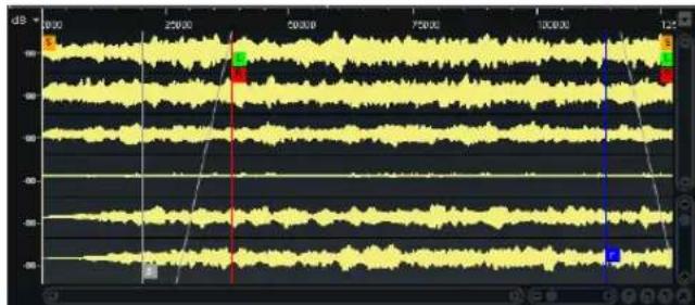
line
| Time | Value | |---------|-------| | 00:00 | 18.0 | | 25:00 | 18.0 | | 30:00 | 18.0 | | 75:00 | 18.0 | | 100:00 | 18.0 | | 125:00 | 18.0 |The following markers are available:
Marker Function
Sample Start Defines where the sample starts to play when a zone is triggered. Audio before this marker is skipped.
Sample End Defines where the sample stops playing. Audio after that marker is ignored.
Sustain Loop Start Defines where the sustain loop starts.
Sustain Loop End Defines where the sustain loop ends. When this marker is reached, playback jumps back to the sustain loop start.
Release Loop Start Defines where the release loop starts.
Marker Function
Release Loop End Defines where the release loop ends. When this marker is reached, playback jumps back to the release loop start.
Release This marker defines the position at which playback starts when a note-off message is received. This allows for a realistic release note-off behavior without the necessity of using extra release samples. To avoid unwanted clicks when jumping to the release marker, you can set a crossfade time and curvature in the parameter section.
Sample Start Range Defines the attack phase of a sample, which can be used for the modulation of the sample start, see "Sample Start Range" on page 81
Selections
Making Selections
To make a selection in the Sample editor, click and drag with the Range Selection tool.

- If Snap to Zero Crossing is activated on the toolbar, the start and end of the selection are always placed at zero crossings.
- You can resize the selection by dragging its left and right border or by [Shift]-clicking.
- The current selection is indicated on the info line. Here, you can change these values numerically.
Defining Sample Start and End from a Selection
- Make a selection, right-click in the Sample editor, open the Selection submenu, and select "Set Sample Start/End to selection".
Creating New Zones from Selections
- Make a selection, right-click in the Sample editor, open the Selection submenu, and select "Create Zone from Selection".
The new zone is inserted below the source zone.
Snapping
Snap to Markers

When the Snap option is activated, you can snap the selection start and end points and markers to other markers.
Snap to Zero Crossing

When this option is activated, markers and selection start and end points are only placed at zero crossings (positions in the audio where the amplitude is zero). This helps you avoid pops and clicks that are caused by sudden amplitude changes.
Auto-Scroll

When this option is activated, the waveform display is scrolled during playback, keeping the playback cursor visible in the editor.
Read Root Key and Tuning from File
This context menu option allows you to set the root key and tuning to the values that are saved in the sample file, if available.
- Right-click in the Sample editor, open the Sample submenu, and select "Read Root Key and Tuning from File". The current zone settings are overwritten by the sample file settings.
This option is only available if the corresponding information is available in the sample file.
Show File in Explorer
- Right-click in the Sample editor, open the Sample submenu, and select "Show in Explorer" (Win) or "Show in Finder" (Mac).
Editing Samples in an External Editor
HALion allows you to specify an external Sample editor application that can be used to perform destructive offline editing on a sample. You can specify the location of this application in the Edit section of the Options editor, see "External Wave Editor" on page 44.
Note that not all sample editors provide the same functionality and that certain features, like transferring the sample loop markers, are not always possible. To get the best results, use Steinberg's WaveLab.
- To load the current sample in an external editor, right-click in the Sample editor, open the Sample submenu, and select "Load into External Editor".
The external sample editor is launched and the sample is transferred.
⇒ The menu entry is only available if you specified an external editor in the Options editor.
To ensure a safe and consistent workflow, HALion creates a copy of the sample and writes it to a temporary folder. This folder can be specified in the Options editor. If none is specified, the temporary folder of the operating system is used.
Changes in the external editor are made to the copy of the sample. When you save the sample in the external editor, HALion recognizes that the temporary file has changed and asks if you want to update the sample.
When writing the sample to the temporary folder, HALion also includes information about loop settings. These can be modified in the external editor, too. When replacing the sample afterwards, the new loop settings are transferred back as well.
→ Sample start/end and release markers cannot be transferred to an external editor.
If a sample is referenced by several zones, transformations of the audio signal are audible for all zones.
When you remove a zone or a program that contains a zone referring to a sample that is still opened in an external editor, you are asked to close the file in the external editor. This enables HALion to delete the temporary file, which is no longer needed.
Channel View Options
The Sample editor allows you to display either all channels, a specific channel, or the sum of all channels. The corresponding options are located to the left of the waveform display. If no selection is made here, all channels are displayed.
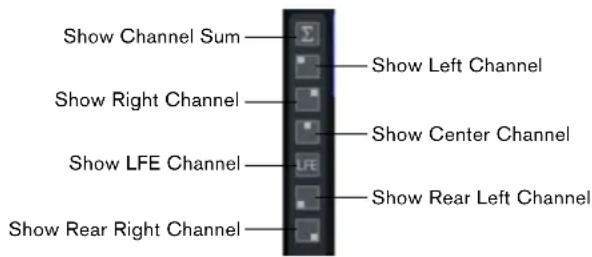
⇒ For stereo samples the surround channel selectors are not available.
Creating Loops
In the Sample editor, you can specify two independent loops, one for the sustain and one for the release phase.
To set up the sustain and the release loop, you can set the start and end positions manually and/or use the functions to automatically detect the positions. For a smooth loop you need to find positions at which the loop end can be continued naturally at the loop start.
The loop settings can be edited using the toolbar options and the handles in the waveform display, but they are also available as numerical values on the Loop tab in the parameters section.
Setting Up a Loop
If the loops are not activated in the zone parameters, no loop markers are shown in the waveform display. When selecting a loop type in the parameters section, the corresponding markers are shown. By activating the Edit Loop function on the Sample editor toolbar, the loop type is set and the loop markers are set to the sample start/end range or the selection, if available.
Selecting a Loop Type
By selecting an option from the Loop pop-up menu on the Loop tab in the parameters section, you define the loop type. The following options are available:
Option Description
No Loop The sample is played without loops. You can also use this option to remove existing loop markers.
Continuous The loop is played continuously until the end of the amplitude envelope.
Once The loop is repeated once.
Until Release (sustain loops only) The loop is repeated until you release the key on the keyboard.
Moving Start and End Markers
The loop start and end markers can be set to suitable positions by dragging the marker handles.
In edit mode, you can also press [Shift] and drag the audio before or after the loop end marker to adjust the end or start position (respectively).
Detecting Loop Start and End Automatically
The loop detection functions search for loop marker positions taking into account similarities within the sample. You can specify the size of the sample portion that has to match before a loop is accepted. Furthermore, you can define the quality that suggested loop markers should match.

To automatically detect a loop, proceed as follows:
- Activate the "Edit Loop" button on the Sample editor toolbar.
- Use the "Find Previous Loop Start/End" or "Find Next Loop Start/End" buttons on the toolbar to detect suitable marker positions.
The loop markers are set accordingly.
The following settings on the Sample editor toolbar also influence the marker detection features:
Option Description
Loop Transition This option allows you to search for rather short loops (t = transition) or longer loops (T = Timbre). It can be useful to search for longer loops if the sample contains longer sound progressions or beats that need to be included. That way you can prevent that the resulting loop becomes static. When set to Timbre, HALion also suggests loop marker positions that might not be optimal regarding the local transition, but reflect best the tonal progression of the sound. In this case, you can use the cross-fade function to smooth out the loop.
Threshold HALion internally detects a large number of possible loop marker positions that are more or less well suited for the loop. These positions are ranked internally according to quality. The Threshold control allows you to specify the ranking level a marker must have so that it can be used. With the highest setting, only few suitable positions are suggested.
Loop Score Each detected loop marker is evaluated and attributed a rating, or score, that provides additional information about how well loop start and end match. Note that this value is only updated when using the loop find functions.
Using Edit Mode
Edit mode is useful to fine-tune and adjust a loop. The waveform is updated to reflect the result of your loop settings.
- To activate edit mode, activate the Edit Loop icon ("e") on the Sample editor toolbar.
- To select which loop (sustain or release) you want to see and adjust in edit mode, click the "Sustain/Release Loop" icon (S/R) on the toolbar.
When the icon is green, you are editing the sustain loop. For the release loop, the icon is red.
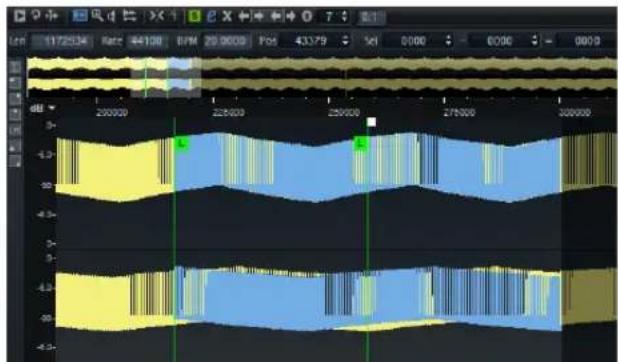
To better see how loop start and end are correlating, a part of the waveform is displayed in blue on top of the loop. This part is taken from an area around the loop start (+/- the loop length) and then shifted to the loop end. The better both waveforms correspond, the smoother the loop will sound.
Setting Up Loop Crossfades
To create smooth loops, you can use crossfades. To set up a loop crossfade, proceed as follows:
- Activate the "e" button on the Sample editor toolbar to enter edit mode.
Crossfade handles are displayed on the waveform. - Click the "Sustain/Release Loop" icon (S/R) on the toolbar to select whether you want to edit the sustain or the release loop.
- Drag the crossfade handles with the mouse, or specify the crossfade range numerically in the parameter section.
To see the effect of the crossfade, you can activate the "Show Resulting Loop Crossfade" option on the toolbar. When this is activated, the resulting waveform is displayed in red.
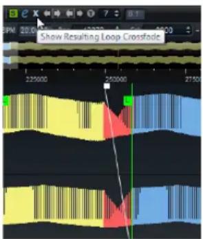
Adjusting the Crossfade Curve
You can specify a linear curve, an equal power curve, or anything in between.
- Drag the middle of the fade curve up or down, or adjust the Curve value in the parameters section.
Adjusting the Tuning
Using the Tuning option on the Loop tab in the parameters section, you can set the tuning of the loop. This is useful to adjust the frequency of the loop.
Using Loopsets A and B
In the Loopset section on the Loop tab in the parameters section, you can set up two different sets of loops for the same sample. This is useful to compare different versions of the same loop, for example.

Additional Loop Options
The following operations can be performed using options from the Sample editor context menu.
Creating Loops from Selections
You can use a selection range as the basis for a loop. Proceed as follows:
- Activate the "Play Selection Looped" icon on the Sample editor toolbar.
- Click the "Play Sample" icon on the toolbar.
- Adjust the selection until you are satisfied with the loop.
- Right-click in the Sample editor, open the Selection submenu, and select "Set Sustain Loop to selection" or "Set Release Loop to selection".
Reading Loop Information from Sample Files
The "Read Loop from File" option allows you to set loop markers to the values that are saved in the sample file.
- Right-click in the Sample editor, open the Sample submenu, and select "Read Loop from File".
The current zone settings are overwritten by the sample file settings.
⇒ This option is only available if the corresponding information is available in the sample file.
Using the Loop Submenu
The Loop submenu on the context menu contains the following options:
Command Description
| Copy Sustain Loop to Release Loop | Copies the start/end marker positions of the sustain loop to the release loop. |
| Copy Release Loop to Sustain Loop | Copies the start/end marker positions of the release loop to the sustain loop. |
| Copy Loop A to B | Copies the settings of loop A to loop B. |
| Copy Loop B to A | Copies the settings of loop B to loop A. |
| Set Sustain Loop to Sample Start/End | Sets the loop start and end marker positions to those of the sample start and end marker. This is useful for drum loops, for example. |
| Set Sample Start/End to Sustain Loop | Sets the sample start and end marker positions to those of the sample loop start and end markers. This can be used to create sliced loops from longer sample files. |
MIDI Editing and Controllers
The MIDI Editor
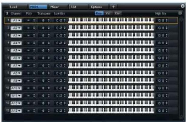
The MIDI editor provides access to the MIDI slot parameters of HALion. This includes MIDI channel, Key and Velocity range, and Transpose and Polyphony settings. Furthermore, you can specify MIDI controllers to be filtered. To switch between velocity range, key range and controller filter, use the buttons above the range controls.
Parameters
Channel
The slot receives MIDI signals on the MIDI port and channel specified here. You can set multiple slots to the same MIDI channel and trigger them simultaneously with the same note events.
Poly (Polyphony)
The Polyphony setting is used to specify how many notes can be played at the same time. Since programs can contain various layers, the resulting number of voices (stereo samples, synth voices etc.) can be much higher than the value specified here.
Transpose
Here you can shift the incoming MIDI notes by ±64 semitones before they are sent to the loaded program.
Key Range (Low Key, High Key)
Each slot can be limited to a certain key range. Set the range with the Low Key and High Key values or by dragging the keyboard range control at its ends. When you click and drag towards the middle of the keyboard, both values are moved at the same time. As an additional option, you can use the MIDI input to set the range. Simply click in a value field and play the note.
To set the key range, proceed as follows:
- At the top of the MIDI editor, click the Key button.
- In the slot, set the key range with the keyboard range controls and/or Low Key/High Key value fields.
Velocity Range (Low Vel, High Vel)
Each slot can be limited to a velocity range. Set the range with the Low Vel and High Vel values or by dragging the graphical velocity range control at its ends. When you click and drag towards the middle of the velocity range control, both values are moved at the same time.
To adjust the velocity range, proceed as follows:
- At the top of the MIDI editor, click the Vel button.
- In the slot, set the velocity range with the velocity range control and/or Low Vel/High Vel value fields.
Controller Filter
You can filter out the most commonly used MIDI controllers for each slot separately. For example, when you set up a keyboard split with bass and piano playing on the same MIDI channel, both sounds will receive the same MIDI controllers. However, you usually do not want the bass to receive the sustain pedal. To avoid that all sounds on the same MIDI channel receive the same MIDI controllers, use the controller filter.
To filter out the most commonly used MIDI controllers, proceed as follows:
- At the top of the MIDI editor, click the Ctrl button.
- In the slot, click the button of the MIDI controller you want to filter out.
The following MIDI controllers and messages can be filtered out: Sustain #64, Foot Controller #4, Foot Switches #65-69, Control Change, Pitchbend, Modulation Wheel #1, and Aftertouch.
Showing Empty Slots
By default the MIDI editor only shows slots that are currently in use by programs.
To show also all empty slots, activate the "Show Empty Slots" option in the title bar.
Using MIDI Controllers
HALion allows you to assign almost any parameter to a MIDI controller. However, you can only assign one parameter of a single zone, layer, effect control, etc. at a time. If you want to use the same MIDI controller for several zones, layers, etc. you have to assign it several times.
A more convenient way to control a zone parameter like the cutoff frequency for all zones, for example is to assign a quick control to that parameter and then assign the MIDI controller to that quick control. Not only can you now control all zones simultaneously, but this way you can also preserve different cutoff settings per zone and just control the offset added by the quick control.
By default, some of the most common parameters like slot volume, pan, as well as the quick controls of each slot are already pre-assigned. The slot AUX FX send modules 1-4 are also pre-assigned and become directly controllable as soon as you load one of the AUX FX send modules on a slot insert effect.
You can customize the factory MIDI controller mapping by assigning your own MIDI controllers using the Learn function.
Assigning MIDI Controllers
-
Right-click the control you want to remote-control.
-
Select "Learn CC" from the menu.
-
On your MIDI keyboard or controller, use the knob, fader, or button.
The next time you right-click the control, the menu shows the assigned MIDI controller.
→ You can assign the same MIDI controller several times to different parameters. However, you cannot assign different MIDI controllers to the same parameter.
- To remove a MIDI controller assignment, right-click the corresponding control, and select "Forget CC".
Setting the Parameter Range
You can set the minimum and maximum values for the parameter separately for each assignment.
- To set the minimum value for the parameter, set the value, right-click the control, and select "Set Minimum".
- To set the maximum value for the parameter, set the value, right-click the control, and select "Set Maximum".
Assigning MIDI Controllers to AUX FX
You can assign the parameters of the AUX FX to MIDI controllers as well. Unlike the slots, the AUX FX do not have a MIDI port and channel of their own. Instead, when learning, they listen to any incoming MIDI controller message, regardless of the MIDI channel. When they are assigned, they keep the specified MIDI channel.
- To assign a MIDI controller, load the effect, right-click the parameter, and assign the controller as described above.
- If you unload or replace the effect, the MIDI controller assignment of this effect is lost.
Saving a MIDI Controller Mapping as Default
After customizing the factory MIDI controller assignments, you can save them as default.
- Open the Options editor and click "Save as Default" in the MIDI controller section.
Now, each time you load a new instance of the plug-in, your customized MIDI controller mapping is available as default.
⇒ “Save as Default” does not include any of the MIDI controller assignments of the AUX FX.
⇒ The current MIDI controller mapping is also saved with each project. This way, you can transfer your settings to other systems. The project also includes the MIDI controller assignments of the AUX FX.
Restoring the Factory MIDI Controller Assignment
To restore the factory MIDI controller assignments, open the Options editor, and in the MIDI controller section, click "Reset to Factory".
Automation and Factory MIDI Controller Assignments
The following parameters show the controller numbers and names of the default factory MIDI controller assignment.
⇒ The assigned MIDI controller numbers are the same for all 64 slots. However, the MIDI controllers listen only to the MIDI channels of the corresponding slot.
Parameter Controller number Name
Volume #07 Volume
Pan #10 Pan
Mute --
Solo --
Send FX 1* #91 Effect 1 Depth
Send FX 2* #92 Effect 2 Depth
Send FX 3* #93 Effect 3 Depth
Send FX 4* #94 Effect 4 Depth
Program #74 Brightness QC 1
Program #71 Harmonic Content QC 2
Program #73 Attack Time QC 3
Program #72 Release Time QC 4
Program #75 Sound Controller #6 QC 5
Program #76 Sound Controller #7 QC 6
Program #77 Sound Controller #8 QC 7
Program #78 Sound Controller #9 QC 8
You can use MIDI controllers inside the modulation matrix of a synth or sample layer, for example, to control the cutoff.
CC 121 Support
HALion can be controlled with the AI knob of Steinberg's CC121 MIDI controller unit.
To change a parameter value, proceed as follows:
-
Move the mouse pointer over the control you want to change.
-
Turn the AI knob to set the value.
⇒ The AI knob only works on parameters that are automatable. This means, for example, that you cannot use the AI knob to change the parameters of the Options editor.
Mixing and Routing
The Audio Bus Architecture
The audio signals of zones, layers, programs, and slots are managed via audio busses. The HALion slots always have one dedicated bus while programs can have one or more audio busses that mix the audio signals from the layers and zones they contain. Layers do not have to have an audio bus. However, you can optionally create audio busses for layers at any time, for example to create a submix of the zones they contain. You can load insert effects on any of these audio busses, for example to process the audio of a single layer or a whole program. In addition, AUX busses allow you to use send effects with zones, layers, programs, and slots. Send effects can be shared between zones, layers, programs, and slots, which saves processing power. Zones do not have an audio bus of their own. Instead, they have outputs that are routed automatically to the next available audio bus. Any of the zones, audio busses, and AUX busses can be assigned freely to one of the stereo outputs or the surround output of the plug-in. For example, a zone output can be routed directly to an output bus, omitting any audio busses and their effects in between.
The Default Audio Signal Flow
Typically, programs are loaded into a slot. Each slot is directly connected to an output bus. The audio busses from the program send their signals to the audio bus of the slot. A program can contain anything from a single zone to a couple of zones, or one or more layers. Layers can contain other layers, which contain zones. The zones output is mixed to the audio busses of the next higher level layers or directly to the program.
To save processing power, audio busses for layers and programs are optional. If a layer has no audio bus, the zones in the layer are automatically routed to the next higher audio bus.
Audio Busses
Audio busses can be compared to channels in a mixer but with much more flexibility when it comes to mixing and routing possibilities. By definition, each slot has at least one audio bus that mixes the audio signals from the layers and zones they contain. Layers do not have an audio bus by default, but you can create audio busses for layers.
Apart from the routing and mixing possibilities, audio busses allow you to load insert effects for processing audio on that bus. Depending on how you set up the audio busses, you can load insert effects on single layers, the whole program or the slot. For example, you can process only the strings of a piano and strings layer sound with a chorus effect, and keep the piano unprocessed. You load insert effects into the effect slots of the channels in the Mixer.
In addition, audio busses allow you to route audio via sends to an AUX bus. This way, you can set up send effects, which can be shared among the layers, programs, and slots. You assign sends directly in the zones or with the effect slots of the channels displayed in the mixer. The sends have an adjustable level, allowing you to control the amount of the effect that is loaded on the AUX bus.
AUX Busses
You need an AUX bus to route individual audio signals from zones or audio busses to AUX effects. HALion provides four of these AUX busses. To set up an AUX effect, load an insert effect into one of the effect slots of the AUX bus. To hear the effect, raise the send level of a zone, route the output of a zone or your audio bus to the AUX bus, or set up a send in the effect rack of your audio bus.
The send levels control the amount of the effect that is loaded into the AUX bus. You can set up sends for each zone and audio bus separately.
By default, the output of an AUX bus is routed to the master output bus, but you can reassign its output to other output busses.
Zones
By definition, the outputs of zones are routed to the first audio bus of the next higher layer or the program. You can reassign the outputs of the zones to any master output.
Layers
To save processing power, audio busses for layers are optional. You can create them at any time in the Program Tree. By default, audio busses of layers route to the first audio bus of the next higher layer or the program. You can reassign the outputs of the audio busses of the layers to any master output.
Programs
By default, the audio busses of programs are routed to the audio bus of the slot holding the program. You can create additional audio busses, for example to create more individual outputs. You can reassign the outputs of the audio busses of the program to any master output.
Slots
A slot outputs its audio busses directly to the master outputs of the plug-in. Each slot has one audio bus. You can reassign the outputs of the audio busses of the slots to any plug-in output bus.
Editing Audio Busses
Creating Audio Busses
To create an audio bus and a corresponding Mixer channel, proceed as follows:
-
In the Program Tree, select the program or layer to which you want to add a bus.
-
Click the "Create New Bus" icon on the toolbar.
Changing the Output Assignment of an Audio Bus
To change the output assignment of an audio bus, open the Mixer and click "Show Depending Bus Channels". In the Program Tree, select a layer, program, or slot with one or more audio busses. All relevant channels are shown in the Mixer. Additional audio busses are displayed at the right of the first audio bus. In the Mixer, click on the output of the audio bus that you want to edit and select an output from the pop-up menu.
⇒ The output busses of the plug-in can be activated in the host sequencer or the Preferences dialog of the standalone version.
Changing the Output Assignment of an AUX Bus
-
In the Mixer, click the "Show AUX busses" button on the toolbar.
-
Click on the output selector of the AUX bus you want to edit and select an output bus from the pop-up menu.
Changing the Output Assignments of Zones
- Select the zones in the Program Tree.
- Open the Sound editor, scroll to the Amplifier section and open the AUX tab.
- From the Output pop-up menu, select a plug-in output or AUX bus.
In addition, you can use the send level knobs of the zones to route individual audio signals to insert effects on AUX busses.
Automatic Bus Width Adaptation
HALion is constantly monitoring the width of all busses in the signal path and adapts to the required width automatically. This may be the case when adding a surround sample zone to a layer that only contains stereo samples so far. In this case, the layer bus and all following busses are set to surround to allow a correct routing. The stereo sample will still be routed correctly to channel one and two.
Another way to change the bus width in the middle of the signal path is to add a surround panner to one of the insert effect slots of a stereo bus. In this case, the output of the bus changes from stereo to surround and forces following busses to do the same.
AUX busses change their bus width, too, if they receive signals from surround sources.
Output busses cannot change their bus width automatically, because they are usually connected to a hardware device. Therefore, the routing to the plug-in output busses has to be changed manually. Make sure that surround slots are routed to the surround output and stereo busses to one of the stereo outputs.
In case your routing is not set up correctly, the corresponding channels show a red warning icon to indicate that the width of two or more busses does not fit and you loose audio channels.
In some cases it might be necessary to connect surround busses to stereo outputs. To avoid losing any of the audio channels, you can add the Downmix effect to one of the inserts. This reduces the bus width to stereo.
Automatic Output Connection
HALion allows you to select outputs in many places. You can find output selectors in zones, layer busses, AUX busses, and slots. Each output can be freely named and the output selectors reflect these names.
Different programs on different slots may contain output configurations that are not available, because busses with the required names are not present in a HALion multi.
In case that connections cannot be established due to different names, a dialog opens showing all pending busses. For each missing bus you can select another bus to be used instead.
Pending busses can also occur when loading layers into programs. In case a layer does not find the required busses, the same dialog opens and you can select another bus.
If an assigned output bus is deactivated in the host, HALion shows a red warning icon on the output channel and the Mixer channels that are connected to it. Nevertheless, you will still be able to hear the signal, because all signals are deviated to the master bus in the background. However, all output selectors remain on their current setting and you can reestablish the connections later, by activating the outputs in your host.
Output Configurations in Different Hosts
Apple Logic 9
In general, HALion provides 32 stereo and one surround output connecting with the host application or a hardware device in standalone. In most applications all of them are available. However, Logic 9 only allows for 16 outputs for a single plug-in. When opening an instance of HALion, you can choose one of four output configurations: Stereo, 5.1-Surround, Multi-Output (1x5.1, 15xStereo), Multi-Output (16xStereo).
Ableton
Ableton Live 8 does not support surround busses.
Sonar 9
Sonar 9 allows to activate all outputs either in mono or stereo. For mono, you get 64 channels for the 32 HALion stereo channels plus six channels for the surround bus. If the stereo outputs are activated, Sonar uses 32 stereo channels plus three stereo channels for the surround bus.
The HALion Mixer
The HALion Mixer editor manages all busses that are available in a HALion instance. These are the 32 stereo output busses plus one surround bus, the 64 slot busses, the 4 AUX busses and a dynamic number of program and layer busses depending on the actual program architecture.
Each bus can be controlled using a dedicated mixer channel, featuring functions like level, pan, mute, solo, and up to eight insert/send effects.
The Mixer editor provides a toolbar that allows you to specify which type of busses you want to see at a given time.
The Toolbar Options
Displaying Different Mixer Channels
AUX Child busses
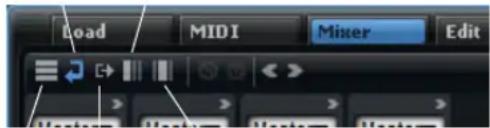
Slot Output Depending busses
To define which mixer channels to display, click one of the show buttons.
Option Description
Slot Shows all slot channels.
AUX Shows the AUX channels.
Output Shows all output channels.
Child busses Shows all the busses that can be found inside the selected program or layer hierarchy.
Depending busses Shows all busses that are in use for the selected program or layer (including AUX busses).
Expanding and Collapsing all Mixer Channels
- To expand all mixer channels at once, click the right arrow button.
Expanded mixer channels provide direct access to the insert/send effects.
- To collapse all mixer channels at once, click the left arrow button.
Collapsed mixer channels only show the most important controls like level, pan, solo, mute, and a level meter.
Showing Empty Slot Channels
If set to "Show Slot Bus Channels", the Mixer editor only shows channels that are currently in use by programs loaded into the corresponding slots. To show all empty slot channels as well, activate the "Show Empty Slots" button.
→ This button is also available in the Slot Rack and the MIDI editor.
Hiding Deactivated Output Channels
If set to "Show Output Bus Channels", the Mixer editor shows all output busses. Deactivated outputs are grayed out. To gain a better overview about which channels are currently used, activate the "Hide Inactive Outputs" button.
The Mixer Channel Strip Controls
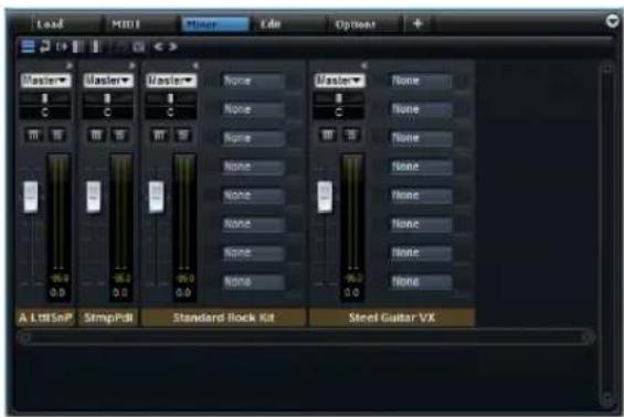
All busses have a similar mixer channel, with a few exceptions. For example, the output busses do not have an output pop-up menu. The various types of channels are using different label colors:
Channel Color
Slot Yellow
Program Blue
Channel Color
Layer Gray
Output Red
AUX Green
Mute
Mutes the bus.
Solo
Mutes all other busses and lets you hear the solo bus only. You can put several channels into solo mode to hear all of them.
Level
The level fader allows to adjust the volume of the bus. All busses allow an amplification of +12 dB.
Pan
By default in the stereo panorama all stereo mixer channels provide a stereo panner that allows to define the position. When working with surround busses, the stereo pan is disabled, but you can use a surround panner to pan the stereo signals in the surround field. This can be achieved by adding a Surround Panner to one of the insert slots. The mixer channel shows a small version of the Surround Panner, which can be used to remote-control the inserted surround panner. Additionally, the Surround Panner provides a level fader for the LFE channel.
⇒ For more detailed editing, use the Sound editor of the Surround Panner.
Meter
The meters of a mixer channel show the output level of the bus. Depending on the number of audio channels of the bus, the number of meters is adapted accordingly. Stereo busses have two channel meters, surround channels six.
Peak Level
The peak level meter indicates the highest level on the bus in dB. To reset, click the peak level.
Channel Label
By default, the channel label shows the name of the bus. Double-click the label to enter a name.
Output
Each channel can be routed to various busses. Click the output pop-up menu and select an output.
⇒ The output busses represent the audio interface to the host application or the audio hardware. Therefore, these channels cannot be routed freely and do not have an output pop-up menu.
→ You can route a surround slot bus to one of the stereo output busses. In this case only the first two channels are connected. To make you aware that the number of channels do not match, HALion displays a warning icon in the top of the mixer channels (slot and output). You can decide whether to add a downmix effect to the output bus, to reroute the slot to the surround output bus, or to leave it as it is.
Insert Effects
Each channel can load up to eight insert effects. To display the inserts, the channel strip needs to be expanded.
Each insert can either be a classical insert effect like a chorus or a delay, or it can load one of the 4 AUX send effects that allow to send the signal to the AUX busses.
When an AUX send effect is loaded, the insert slot adds a small level fader below. Use this fader to set the level that is send to the AUX bus.
→ You cannot use send effects on AUX and output busses.
Pre-Fader Send Effects
By default, send levels are influenced by the level of the bus. If you want to adjust the send level independently from the bus level you can set the send to pre-fader. This can be done by activating the corresponding button to the left of the level fader.
Changing the Order of Effects
You can change the order of effects by dragging them to another position. When dropping a slot directly onto another slot, they exchange their positions.
The Program Tree synchronizes directly with the Mixer. When adding an effect on a bus in the Program Tree, this effect is also shown in the Mixer channel. The first 8 effects are visible in the Mixer.
Effects Reference
Introduction
HALion comes with a collection of high-quality studio effects. These effects are described in the following sections.
Reverb and Delay Effects
REVerence
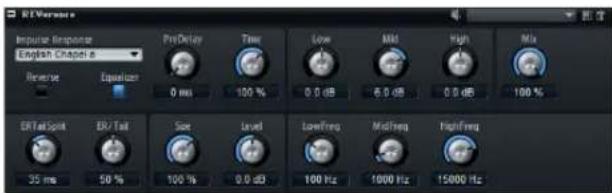
REVerence is a convolution tool that allows you to apply room characteristics (reverb) to the audio. By recording an impulse in a room, you get the characteristics of the room. Convolution superimposes these characteristics to the sound. The result is a very natural sounding reverb. Included with this effect is a collection of high-quality reverb impulse responses.
Impulse Response
By selecting an impulse response you determine the basic sound character of the reverb.
Reverse
Activate this to reverse the impulse response.
PreDelay
This determines the amount of time between the dry signal and the onset of the reverb. With higher predelay values you can simulate larger rooms.
Time
This controls the reverb time. At a setting of 100% the impulse response is applied with its original length.
Size
This scales the size of the simulated room. At a setting of 100 % the impulse response is applied as recorded in the original room.
Level
Here you can adjust the level of the impulse response.
Equalizer
Activates the built-in three-band equalizer.
ER Tail Split
This sets the split point between the early reflections and the reverb tail.
ER/Tail Mix
This sets the balance between the early reflections and the reverb tail. At a setting of 50 % the early reflections and the tail have the same volume level. Settings below 50 % raise the early reflections and lower the tail, as a result the sound source moves towards the front of the room. Settings above 50 % raise the tail and lower the early reflections, as a result the sound source moves towards the back of the room.
Reverb
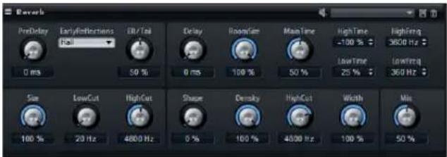
This effect produces a high-quality algorithmic reverb with early reflections and reverb tail. The early reflections are responsible for the spatial impression in the first milliseconds of the reverb. For emulating different rooms you can choose from different early reflections patterns and adjust their size. The reverb tail, or late reverberation, offers parameters for controlling the room size and the reverb time. You can adjust the reverb time individually in three frequency bands.
PreDelay
This determines the amount of time between the dry signal and the onset of the reverb. With higher predelay values you can simulate larger rooms.
Early Reflections
Here you select an early reflections pattern. The early reflections pattern contains the most important delays that deliver the key information for the spatial impression of the room.
ER/Tail Mix
This sets the balance between the early reflections and the reverb tail. At a setting of 50 % the early reflections and the tail have the same volume level. Settings below 50 % raise the early reflections and lower the tail, as a result the sound source moves towards the front of the room. Settings above 50 % raise the tail and lower the early reflections, as a result the sound source moves towards the back of the room.
Size
This adjusts the length of the early reflections pattern. At a setting of 100 % the pattern is applied with its original length and the room sounds the most natural. At settings smaller than 100 % the early reflections pattern is compressed and the room is perceived smaller.
Low Cut
This attenuates the low frequencies of the early reflections. The higher this value, the less low frequencies the early reflections will have.
High Cut
This attenuates the high frequencies of the early reflections. The lower this value, the less high frequencies the early reflections will have.
Delay
This delays the onset of the reverb tail.
Room Size
This parameter controls the dimensions of the simulated room. At a setting of 100 % the dimensions correspond to a cathedral or a large concert hall. At a setting of 50 % the dimensions correspond to a medium sized room or studio. Settings below 50 % simulate the dimensions of small rooms or a booth.
Main Time
This controls the overall reverb time of the tail. The higher this value, the longer the reverb tail will decay. At a setting of 100 % the reverb time is infinitely long. The Tail Main Time parameter also represents the mid band of the reverb tail.
High Time
This controls the reverb time for the high frequencies of the reverb tail. When you set positive values the decay time of the high frequencies is longer, when you set negative values it is shorter. Frequencies are affected depending on the Tail High Freq parameter.
High Freq
This sets the cross-over frequency between the mid and the high band of the reverb tail. You can offset the reverb time for frequencies above this value from the main reverb time with the Tail High Time parameter.
Low Time
This controls the reverb time for the low frequencies of the reverb tail. When you set positive values the decay time of the low frequencies is longer, when you set negative values it is shorter. Frequencies are affected depending on the Tail Low Freq parameter.
Low Freq
This sets the cross-over frequency between the low and the mid band of the reverb tail. You can offset the reverb time for frequencies below this value from the main reverb time with the Tail Low Time parameter.
Shape
This controls the attack of the reverb tail. At a setting of 0 % the attack is more immediate, which is a good setting for drums. The higher this value, the less immediate the attack.
Density
This adjusts the echo density of the reverb tail. At a setting of 100 % single reflections from walls cannot be heard. Lower this value to hear more single reflections.
High Cut
This attenuates the high frequencies of the reverb tail. The lower this value, the less high frequencies the reverb tail will have.
Width
This adjusts the output of the reverb signal between mono and stereo. At a setting of 0 % the output of the reverb is mono, at 100 % stereo.
Mix
This sets the ratio between the dry and wet signal.
Multi Delay
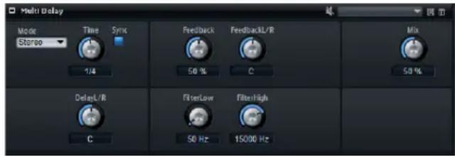
This effect produces echoes, so-called delays, with adjustable time, feedback, and filters. With the Mode parameter you can set up this effect as Stereo, Cross, or Ping-Pong Delay effect. Depending on the selected mode, the echoes repeat in varying patterns across the stereo panorama.
Mode
Multi Delay offers three different modes:
Mode Description
Stereo This mode has two independent delay lines, one for the left and one for the right audio channel, each with a feedback path of its own.
Cross This mode has two delay lines with cross feedback. Cross feedback means that the delay of the left channel is fed back into the delay of the right channel, and vice versa.
Ping-Pong This mode mixes the left and right input channel and sends it to hard-panned left and right delays. This way, the echoes bounce like a ping-pong ball between left and right in the stereo panorama.
Time
This sets the overall time for the left and right delay in milliseconds. Use the Delay L/R parameter to shorten the time for the left or right delay. Activate Sync to set the delay time as a note length value.
Sync
Activate Sync to synchronize the delay time to the host tempo. When activated, the time is set as a note length value.
If the note length exceeds the maximum delay time of 5000 ms, because your song tempo is very slow, for example, the note length is halved internally in order to not exceed the maximum possible delay time.
Delay L/R
This offsets the time of the left or right delay from the overall delay time. The offset value is a factor. At a factor of 1, the right or left delay time has the same length as the overall delay time. At a factor of 0.5, the time is half as long as the overall delay time. To offset the left delay time, turn the control to the left. To offset the right delay time, turn the control to the right. The letter before the factor changes accordingly to "L" or "R". The mid position of the control sets a factor of 1.0, which is the neutral setting.
Feedback
This sets the overall amount of feedback for the left and right delay. Feedback means that the output of the delay is fed back to its input. Depending on the amount you set, the echoes repeat more or less often. At a setting of 0% you hear one echo. At a setting of 100% the echoes repeat endlessly.
Feedback L/R
This parameter is only available in Stereo Delay mode. Use this to offset the amount of feedback of the left or right delay from the overall feedback. The offset value is a factor. A factor of 1 means that the amount of feedback corresponds to the overall feedback. A factor of 0.5 means that the amount is half the overall feedback. To offset the left feedback, turn the control to the left. To offset the right feedback, turn the control to the right. The letter before the factor changes accordingly to "L" or "R". The mid position of the control sets a factor of 1.0, which is the neutral setting.
Filter Low
This allows you to attenuate the low frequencies of the delays.
Filter High
This allows you to attenuate the high frequencies of the delays.
Mix
This sets the ratio between the dry and the wet signal.
EQ Effects
Studio EQ
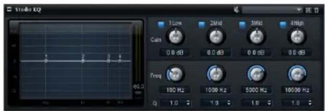
This is a high-quality 4-band parametric equalizer. With the four frequency bands 1 Low, 2 Mid, 3 Mid, and 4 High, you can shape the tone color, to create a brighter or darker sound, for example. The two mid-range bands act as peak filters and the low and high bands act as shelving filters. All bands are fully parametric with adjustable gain, frequency, and Q factor.
Each frequency band offers the following controls:
| Control Description | |
| Gain | Sets the amount of cut or boost for the corresponding band. |
| Freq | Sets the frequency that is cut or boosted with the Gain parameter. |
| Q (Quality) Use this to adjust the bandwidth of the mid-range peak filters from wide to narrow. By increasing the Q on the low and high shelving filters you can add a dip to their shape. | |
- Adjust the equalizer controls Gain, Freq, and Q.
- To adjust Gain and Freq simultaneously, drag the points in the EQ graph in the display.
Graphic EQ
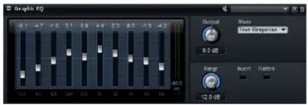
This equalizer has ten frequency bands that can be cut or boosted by up to 12dB with a fader. In addition, there are general controls for setting the overall range and output of the equalizer.
Output
This controls the overall output level of the equalizer.
Mode
The Mode option allows you to add color or character to the equalized output. The following options are available:
Mode Description
True Response Serial filters with accurate frequency response.
Classic Parallel filters where the resonance depends on the amount of gain.
Constant Q Parallel filters where the resonance is raised when boosting the gain.
Range
This adjusts the maximum cut or boost in dB for all frequency bands together.
Invert
Activate this to invert the EQ curve. The frequency bands that are boosted are cut, and vice versa.
Flatten
Click this button to reset all frequency bands to 0 dB.
Distortion Effects
Amplifier
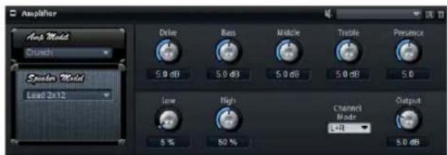
This effect emulates the sound of an amplifier with speakers. There are different amplifiers and speaker models you can combine.
Amp Model
Here you select the type of amplifier. The sound character of the overdrive changes with the amplifier you select. To bypass the amplifier, select No Amp.
Speaker Model
Here you select the type of speaker model. Each model colors the sound uniquely. To bypass the model, select "No Speaker".
Drive
This adjusts the amount of overdrive.
Bass
This adjusts the tone color of the low frequencies.
Middle
This adjusts the tone color of the mid frequencies.
Treble
This adjusts the tone color of the high frequencies.
Presence
This adds brightness.
Low Damp
Attenuates the low frequencies of the speakers.
High Damp
Attenuates the high frequencies of the speakers.
Channel Mode
Here you can define which output channels of the amplifier deliver a distorted signal. You can set it to L (Left), R (Right) or L/R (Both). When set to L or R, the other channel provides a clean signal.
Output
This controls the output level of the amplifier.
Distortion
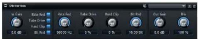
This effect offers the whole range of distortion, from low fidelity, digital distortion to high fidelity, analog sounding distortion. The four available types of distortion (Rate Red, Tube Drive, Hard Clip, and Bit Red) can be freely combined.
In Gain
This adjusts the input level of the sound.
Rate Red (Rate Reduction)
Rate reduction distorts the sound by means of aliasing. Enable the Rate Red option to activate the Rate Red control that adjusts the amount of aliasing. The lower the setting, the more aliasing is added.
Tube Drive
This adds warm, tube-like distortions to the sound. Enable the Tube Drive option to activate the Tube Drive control that adjusts the amount of distortion. The higher the setting, the more distortion is added.
Hard Clip
This adds bright, transistor-like distortions to the sound. Enable the Hard Clip option to activate the Hard Clip control that adjusts the amount of distortion. The higher the setting, the more distortion is added.
Bit Red (Bit Reduction)
Bit reduction distorts the sound by means of quantization noise. Enable the Bit Red option to activate the Bit Red control that adjusts the amount of quantization noise. The lower the setting, the more quantization noise is added.
Out Gain
This adjusts the output level of the sound.
Mix
This controls the mix between the dry and the wet signal.
Modulation Effects
Chorus

The Chorus effect thickens and broadens the sound by means of pitch modulation.
Rate
Use this to specify the frequency of the pitch modulation in Hertz (Hz).
Sync
Activate this to set the Rate value in fractions of beats.
Depth
This sets the intensity of the pitch modulation.
Phase
This widens the sound image of the effect from mono to stereo.
Shape
This adjusts the characteristic of the modulation. At a setting of 0 % the pitch changes continuously, producing a steady modulation. At a setting of 100 % the pitch does not change all the time, producing a less steady modulation.
Mix
This controls the mix between the dry and the wet signal.
Flanger

The Flanger effect thickens and broadens the sound by means of pitch modulation. The Feedback parameter allows you to add resonances allowing for jet-like sweeps of the sound.
Rate
Use this to specify the frequency of the pitch modulation in Hertz (Hz).
Sync
Activate this to set the Rate value in fractions of beats.
Depth
This sets the intensity of the pitch modulation.
Phase
This widens the sound image of the effect from mono to stereo. The Phase parameter also changes the characteristic of the Cross Feedback parameter.
Shape
This adjusts the characteristic of the modulation. You hear this best with the Feedback parameter turned on. At a setting of 0 % the sound sweeps linearly up and down. At a setting of 100 % the sound sweeps exponentially up and down.
Mix
This controls the mix between the dry and the wet signal.
Feedback
This adds resonances to the effect.
Cross FB
This mixes the feedback of the left channel with the right channel, and vice versa. This parameter only takes effect if the Feedback parameter is set to a value above 0 %. The setting of the Phase parameter influences the Cross FB parameter.
Tone
This adjusts the tone color of the feedback. If you set this parameter to lower values the feedback is less bright.
Phaser

The Phaser effect thickens and broadens the sound by means of phase modulation. The Feedback parameter allows you to add resonances to sweep the sound.
Rate
Use this to specify the frequency of the phase modulation in Hertz (Hz).
Sync
Activate this to set the Rate value in fractions of beats.
Depth
This sets the intensity of the phase modulation.
Shift
This shifts the phase modulation upwards to higher frequencies of the spectrum.
Phase
This widens the sound image of the effect from mono to stereo.
Low Cut
Attenuates the low frequencies.
High Cut
Attenuate the high frequencies.
Mix
This controls the mix between the dry and the wet signal.
Tremolo

This effect produces amplitude modulation, that is cyclic modulation of the level of the sound.
Rate
Use this to specify the frequency of the amplitude modulation in Hertz (Hz).
Sync
Activate this to set the Rate value in fractions of beats.
Depth
This sets the intensity of the amplitude modulation.
Phase
This widens the sound image of the effect from mono to stereo.
Output
Sets the output level of the Tremolo.
Rotary
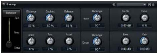
The Rotary effect emulates the sound of a vintage rotary speaker including amplifier, horn, drum, and cabinet. By emitting the sound via a rotating horn and drum, the rotary speaker produces a Doppler effect that thickens the sound. The horn and drum rotate at variable speed producing different amounts of Doppler effect. The amplifier of the rotary speaker adds a warm sounding distortion, and
the horn, drum, and cabinet color the sound uniquely. The horn and drum are recorded via (virtual) microphones that can be set to different angles to broaden the sound image. Typically, rotary speakers are used with electric organs.
Rotation
Use this to change the rotation speed of the horn and drum (Slow, Fast, Stop). When set to Fast, the Doppler effect is stronger. When set to Stop, there is no Doppler effect because the drum and horn do not rotate. Because the horn and drum accelerate and decelerate at different speeds the transition from Slow to Fast and vice versa sounds the most interesting.
Distance
Sets the distance between the microphones and the horn and drum. The amplitude modulation of the sound decreases with the distance of the microphones. Set this to higher values for less amplitude modulation.
Cabinet
The horn and drum sound different when recorded through the louvers of the cabinet. Use this to color the horn and drum with the sound of the cabinet. At a setting of 100 % you get the full sound of the cabinet.
Balance
Here you adjust the balance between the horn and drum microphones. At a setting of 0 % you hear only the drum. At a setting of 100 % you hear only the horn.
Slow
This adjusts the slow speed of the horn and drum together.
Fast
This adjusts the fast speed of the horn and drum together.
Accel
Adjusts the acceleration time for raising and lowering the rotation speed of the horn and drum.
Horn Mic Angle
This adjusts the stereo spread of the horn microphones. At a setting of 0^ the sound image is monophonic. At a setting of 180^ the sound image is fully stereo.
Drum Mic Angle
This adjusts the stereo spread of the drum microphones. At a setting of 0^ the sound image is monophonic. At a setting of 180^ the sound image is fully stereo.
Treble
Use this to adjust the tone color of the high frequencies.
Drive
Here you can adjust the distortion of the amplifier.
Bass
Use this to adjust the tone color of the low frequencies.
Gain
Use this to set the output level of the rotary speaker.
Vibrato

The Vibrato effect emulates the chorus and vibrato effects of vintage organs. It thickens the sound by means of pitch modulation. The effect provides direct access to the classic chorus and vibrato settings (C1, C2 and C3 and V1, V2 and V3). In addition, there is a Custom mode that allows to adjust the amount of chorus or vibrato freely.
Type
Here you can select the classic chorus and vibrato settings C1, C2 and C3 and V1, V2 and V3. The control is only available if the effect is set to Classic mode.
Custom Mode
Activate this to adjust the chorus and vibrato settings freely with the Rate, Depth, and Vibrato/Chorus controls.
Rate
Use this to specify the frequency of the pitch modulation in Hertz (Hz).
Depth
This sets the intensity of the pitch modulation.
Vibr/Chor
This controls the mix between the vibrato and the chorus signal. At a setting of 100 % you only hear the chorus effect.
Dynamics Effects
Compressor
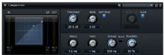
The Compressor reduces the dynamic range of a sound. This way, the sound gains headroom. You can use this extra headroom to make the overall sound louder again. The graphical control to the left indicates the compression curve. You can edit the Threshold and Ratio value with the handles of this control, the corresponding knobs reflect your changes. The input and output VU meters indicate the level before and after the compression. The Gain Reduction meter indicates the current attenuation of the level.
Threshold
Use this to set the threshold in dB. Sounds that are louder than the threshold are reduced in gain. Sounds below the threshold stay untreated.
Ratio
This adjusts the amount of gain reduction for sounds that are louder than the threshold. The higher the ratio, the more the output is lowered. For example, if the ratio is set to 2:1 and the amplitude of the sound is 4 dB above the threshold, the output is lowered by 2 dB. If the amplitude is 8 dB above the threshold, the output is lowered by 4 dB.
Soft Knee
If this button is off, signals above the threshold are compressed instantly according to the set ration (hard knee). When Soft Knee is activated, the onset of compression is more gradual, producing a less drastic result.
Make-Up
Depending on the set threshold and ratio, the sound loses gain (indicated by the Gain Reduction meter). You can use the Make-Up parameter to make the overall sound louder again.
Auto
This calculates the gain loss from the Threshold and Ratio settings and sets the Make-Up value automatically. The Make-Up knob is disabled when Auto is active.
Attack
This determines how fast the Compressor effect reacts to sounds that exceed the set threshold. The longer the set Attack time, the longer the period for reducing the gain to the set ratio will be. In other words, with longer Attack times the onset of sounds exceeding the threshold pass through unprocessed.
Hold
This sets a time period during which the compression is applied after the sound exceeds the set threshold.
Release
This determines how fast the Compressor effect reacts to sounds that fall below the set threshold. The longer the set Release time, the longer the period for returning to the original level will be.
Auto Release
Activate this to set the Release time automatically. The Compressor analyzes the input sound continuously to find the optimal Release time. The Release knob is disabled when Auto Release is active.
Peak - RMS
Determines whether the input signal is analyzed according to peak or RMS values or a mixture of both. At a setting of 0 % the Compressor uses Peak sensing only and at 100 % RMS sensing only. Peak means that the Compressor directly senses the peak level of the sound. RMS is an abbreviation for root mean square, a statistical measure for the amplitude of sounds. RMS means that the Com-
pressor senses the average power of the sound. Peak sensing responds faster than RMS sensing. Typically, Peak sensing is used for transient and RMS sensing for sustained sounds.
Limiter
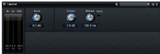
The Limiter effects prevents the sound from exceeding the set output level to avoid clipping in following effects, for example. The input and output VU meters indicate the level before and after the Limiter. The Gain Reduction meter in the middle indicates the current attenuation of the level.
Input
This adjusts the input level of the sound. By increasing the input level you can drive the sound more and more into limiting.
Output
This sets the maximum output level of the sound.
Release
This sets the time that the gain needs to return to its original level. The longer the Release time, the longer is the period for returning to the original level.
Auto
Activate this to set the Release time automatically. The Limiter analyzes the input sound continuously to find the optimal Release time. The Release knob is disabled when Auto Release is active.
Expander
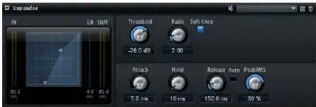
Expander reduces the output level in relation to the input level for signals below the set threshold. This is useful when you want to enhance the dynamic range or reduce the noise in quiet passages. The graphical control to the left indicates the expansion curve. You can edit the Threshold and Ratio value with the handles of this control, and the corresponding knobs reflect your changes. The input and output VU meters indicate the level before and after the expansion. The Gain Reduction meter indicates the current attenuation of the level.
Threshold
Use this to set the threshold in dB. Sounds that are softer than the threshold are reduced in gain. Sounds above the threshold stay untreated.
Ratio
This adjusts the amount of gain reduction for sounds that are softer than the threshold. The higher the ratio, the more the output is lowered. For example, if the ratio is set to 2:1 and the amplitude of the sound is 4 dB below the threshold, the output is lowered by 2 dB. If the amplitude is 8 dB below the threshold, the output is lowered by 4 dB.
Soft Knee
If this button is off, signals above the threshold are compressed instantly according to the set ration (hard knee). When Soft Knee is activated, the onset of expansion is more gradual, producing a less drastic result.
Attack
This determines how fast the Expander reduces the gain when the sound falls below the set threshold. The longer the Attack time, the longer the period for reducing the gain will be.
Hold
This sets a time period during which the expansion is applied after the sound falls below the set threshold.
Release
This determines how fast the Expander raises the gain after the sound exceeds the set threshold. The longer the Release time, the longer is the period for raising the gain again.
Auto Release
Activate this to set the Release time automatically. The Expander analyzes the input sound continuously to find the optimal Release time. The Release knob is disabled when Auto Release is active.
Peak - RMS
Determines whether the input signal is analyzed according to peak or RMS values or a mixture of both. At a setting of 0% the Expander uses Peak sensing only and at 100% RMS sensing only. Peak means that the Expander directly senses the peak level of the sound. RMS is an abbreviation for root mean square, a statistical measure for the amplitude of sounds. RMS means that the Expander senses the average power of the sound. Peak sensing responds faster than RMS sensing. Typically, Peak sensing is used for transient and RMS sensing for sustained sounds.
Gate
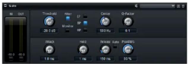
The Gate effect passes sound only to its output if the input sound exceeds the set threshold level. Sounds below the threshold are silenced. An internal side-chain filter allows you to analyze a filtered version of the input sound instead. This way, the Gate detects only certain frequencies of the input sound.
Threshold
This setting determines the level where the gate is activated. Signal levels above the set threshold trigger the gate to open, and signal levels below the set threshold close the gate.
Filter
This activates the internal side-chain filter. When activated, the input sound is filtered before it is analyzed. The Gate opens only if the filtered sound exceeds the set threshold. When the Filter button is off, the filter controls are disabled.
Filter Type
Here you select the filter type for the side-chain filter. Select high-pass (HP) to detect high, band-pass (BP) to detect mid, and low-pass (LP) to detect low frequencies only.
Monitor
Activate this to listen to the sound of the side-chain filter. The Gate is inactive when the Monitor button is activated.
Center
This sets the center frequency of the side-chain filter.
Q-Factor
Activate this to adjust the bandwidth of the band-pass filter from wide to narrow.
Attack
This determines how fast the Gate opens when the sound exceeds the set threshold. The longer the Attack time, the longer is the period for the sound to fade in.
Hold
This sets a time period during which the Gate is applied after the sound falls below the set threshold.
Release
This determines how fast the Gate closes after the sound falls below the set threshold. The longer the Release time, the longer is the period for the sound to fade out.
Auto
Activate this to set the Release time automatically. The Gate analyzes the input sound continuously to find the optimal Release time. The Release knob is disabled when Auto Release is active.
Peak - RMS
Determines whether the input signal is analyzed according to peak or RMS values (or a mixture of both). At a setting of 0% the Gate uses Peak sensing only and at 100% RMS sensing only. Peak means that the Gate directly senses the peak level of the sound. RMS is an abbreviation for root mean square, a statistical measure for the amplitude of sounds. RMS means that the Gate senses the average power of the sound. Peak sensing responds faster than RMS sensing. Typically, Peak sensing is used for transient and RMS sensing for sustained sounds.
Panner and Routing Effects
Stereo Pan

This effect allows you to set the stereo position and width of the signal.
Input Swap
Activate the Input Swap option if you want to swap the stereo channels.
Pan
Here you can set the pan position of the signal. The panning is available for mono and stereo input signals.
Width
This parameter allows you to adjust the stereo width of the signal from stereo to mono.
Surround Panner
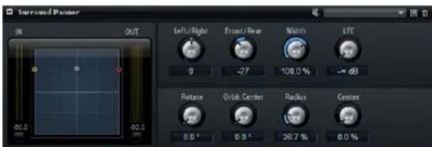
The Surround Panner allows you to position a signal in a two-dimensional surround field. You can either pan the left/right and the front/rear position independently using the corresponding knobs or use the positioning handle to control both positions at the same time.
Restricting Movement
By default, you can click anywhere in the pan area and drag the mouse to move the sound source. If you want the positioning handle to jump to a specific position, you can click once at that position.
However, you can also limit movement to a specific direction, using the corresponding modifier keys. That way you can scale down your movements, or have the surround source move along a certain axis.
The following modes are available:
Modifier key(s) Description
- Standard mode, no restrictions apply.
[Shift] Mouse movements are scaled to allow very fine movements. This is useful when panning in the miniature display in the mixer channel, for example.
[Ctrl]/[Command] Horizontal movements only.
[Ctrl]/[Command]-[Shift] Vertical movements only.
[Alt]/[Option] Diagonal movement only (bottom left to top right).
[Alt]/[Option]-[Shift] Diagonal movement only (bottom right to top left).
[Shift]-[Ctrl]/[Command]-In this mode the mouse pointer immediately jumps to the positioning handle even if it's located outside the pan area.
Left / Right
Adjusts the horizontal (X) position of the audio signal.
Front / Rear
Adjusts the depth (Y) position of the audio signal.
Width
Controls the width of the stereo input signal from 0% (mono) over 100% (Stereo) to 141.4% (Expanded Stereo).
LFE
This parameter controls the level of the Low Frequency Effects channel.
Rotate
Rotates the source channels around the positioning handle. All input channels circle around the handle (without moving beyond the borders of the surround field).
Orbit Center
Use this parameter if you want to rotate the complete signal around the center of the surround field.
Radius
Changes the distance of the signal from the orbit center. By default, the radius is set to 100%, but you can lower it to get closer to the center or increase it to orbit on a larger circle.
Center Distribution
The Center Distribution control is used to distribute part or all of the signal to the left and right front speakers. This can be used to widen the center signal. At 100 % the center source is provided entirely by the phantom image created by the left and right speakers. This can be useful if you want to rotate the surround signal without using the center speaker at all, for example.
A blue line at the top of the surround field indicates the distance up to which a phantom signal is added. If you position the source signal inside this range, the signal is sent to all three channels.
Channel Router
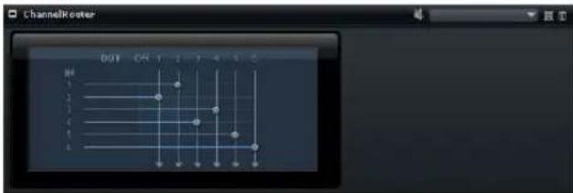
This effect allows you to change the channel routing of the bus to adapt the channel format to different multi-channel samples. Each of the six input channels can be routed to a specific output channel.
Downmix
This effect allows you to downmix a surround signal to a stereo signal.
⇒ There are no controls on the editor of this effect, because the downmix is done automatically.
HALion 3 Legacy Effects
In addition to the standard HALion effects, a number of effects from HALion 3 is also provided. These effects can be selected from the Legacy submenu of the Effects menu.
Hall Reverb
A simple reverb with adjustable pre-delay and damping.
Parameter Description
Predelay The Predelay time delays the wet signal to simulate larger acoustic spaces or as a slap-back effect.
Time Length of reverb tail.
HF Damp Progressive damping of high frequencies.
Lo EQ Low-cut EQ.
Hi EQ High-cut EQ.
Mix Wet/dry mix.
Non-Linear Reverb
A "gated" reverb with a sharp cutoff.
Parameter Description
| Time | Length of reverb tail. It also allows you to change the sound from dense early reflections to a trashy, grainy 80's-type reverb. |
HF Damp Progressive damping of high frequencies.
Lo EQ Low-cut EQ.
Hi EQ High-cut EQ.
Mix Wet/dry mix.
Early Reflections
A short, dense reverb for simulating small acoustic spaces and to thicken or blur sounds.
Parameter Description
| Time Length of reverb tail. It also allows you to change the sound from dense early reflections to a trashy, grainy 80's-type reverb. |
Low EQ Low-cut EQ.
High EQ High-cut EQ.
Mix Wet/dry mix.
Delay
A simple mono-in/stereo out delay.
Parameter Description
| Delay Delay time. If the Sync parameter is set to On, the delay time is set using various note values. |
Sync On/Off By activating Sync, delays are synced to the tempo set in your host application.
Feedback Feedback controls the number of delay repeats.
Balance Ratio of left delay time to right delay time.
HF Damp High-cut filter to soften delay repeats.
Stereo Delay
A stereo-in/stereo out delay.
Parameter Description
| Delay Delay time. If the Sync parameter is set to On, the delay time is set using various note values. |
| Feedback | Feedback controls the number of delay repeats. For minimum feedback set the slider to the mid position. By moving the slider to the left or right “cross delay” is applied, where left output feeds back into right input or vice versa. |
Parameter Description
| Sync On/Off By activating Sync, delay repeats are synced to the tempo set in your host application. |
Balance Ratio of left delay time to right delay time.
HF Damp High-cut filter to soften delay repeats.
Long Delay
The Long Delay provides the same parameters set as the Delay, except delays up to four seconds can be set.
Tape Delay
Simulation of a vintage 4-head analog tape delay.
Parameter Description
| Delay Delay time. If the Sync parameter is set to On, the delay time is set using various note values. |
Sync On/Off By activating Sync, the delay repeats are synced to the tempo set in your host application.
Feedback Feedback controls the number of delay repeats.
Vintage Amount of vintage "color" and tape flutter.
Head 1 Delay level 1 (output is panned left).
Head 2 Delay level 2 (output is panned right).
Head 3 Delay level 3.
Head 4 Delay level 4.
Pan 3+4 Varies the panning of delays 3 & 4 from center to hard left/right.
Vol 3+4 Varies the volume of delay outputs 3 & 4.
Chorus
A straightforward chorus effect that can be used to "widen" sounds.
Parameter Description
| Rate | Modulation rate. |
Depth Amount of pitch modulation.
Predelay Initial delay, to vary the "tightness" of the chorused voices to the dry signal.
Mix Wet/dry mix.
Ensemble
Chorus with a more complex modulation waveform for a lively thickening effect.
Parameter Description
Rate Modulation rate.
Depth Amount of pitch modulation.
Shimmer Creates a more complex modulation effect.
Width Stereo width adjustment.
Mix Wet/dry mix.
Flanger
A classic flanger effect.
Parameter Description
Rate Sweep rate.
Depth Sweep depth.
| Feedback | Feedback amount. Increase for a more intense flanging effect. |
| Predelay | Initial delay. Adjusts the minimum delay time/maximum flange frequency. |
Mix Wet/dry mix.
Phaser
A four pole phaser for subtle phasing effects.
Parameter Description
Rate Sweep rate.
Depth Sweep depth.
Feedback Feedback amount. Increase for a more pronounced effect.
Stereo Offset between left and right modulation.
Center Sets the center frequency around which the modulation occurs.
Mix Wet/dry mix.
Pan / Tremolo
Autopan and Tremolo effect as used in vintage electric pianos.
Parameter Description
Rate Sweep rate.
Phase Relative phase of left and right channel amplitude modulation, to vary from tremolo to autopan.
Shape Shape of modulation waveform from thin pulse, through sine, to fat pulse.
Mix Wet/dry mix.
Stereo Width
A stereo width enhancer with 4 modes.
Parameter Description
Mode Selects between four modes of stereo width enhancement:
- Adjust: Adjust existing width of stereo signal.
- Swap: As Adjust but swaps left and right channels.
- Comb: A stereo comb filter effect.
- Haas: Synthesizes stereo width by delaying one channel.
Delay Delay time (not used in Adjust and Swap modes).
Width Overall width adjustment.
Low/Mid/High Width adjustment for low/mid/high frequencies.
Output Output level trim.
Rotary Speaker
Simulation of a rotary speaker cabinet with high and low rotors.
Parameter Description
Rate Master speed control: Stop, Slow, Fast.
Dirt Amount of overdrive.
Lo/Hi Crossover frequency between low and high rotors.
Width Stereo width.
Tone Adjust the tone of the overdriven signal.
Hi/Lo Speed Speed of high and low rotor.
Hi/Lo Acc Acceleration of high and low rotor.
Mix Wet/dry mix.
Wah Pedal
An auto-wah effect.
Parameter Description
Rate Modulation rate (optional tempo sync).
Depth Modulation depth.
Pedal Adjusts filter frequency.
Mode - Auto: Envelope controlled wah effect.
- Pedal: No modulation, Pedal parameter sets the frequency.
- Mod: LFO modulation. Rate parameter controls the modulation rate.
Resonance Sets the amount of filter resonance.
Tracking Adjusts envelope tracking speed in Auto mode, and envelope rate modulation in Mod mode.
TalkBox
Modulated vowel formant filter.
Parameter Description
Rate LFO Modulation rate (optional tempo sync).
Depth LFO modulation depth.
Vowel Center setting: Vowel produced when there is no modulation.
Env Mod Amount of vowel modulation by input signal level.
Env Att Rate of response to a rising input signal level.
Env Rel Rate of response to a falling input signal level.
Mix Wet/dry mix.
Shelf EQ
Simple tone control.
Parameter Description
Output Output level trim.
Bass Low frequency cut/boost.
Treble High frequency cut/boost.
Parametric EQ
Two-band parametric equalizer.
Parameter Description
Gain 1/2 Cut/boost amount for the two bands.
Freq 1/2 Sets the center frequency for the two bands.
Width 1/2 Sets the band width for the two bands ("Q").
Output Output level trim.
Enhancer
Psycho acoustic spectrum shaping.
Parameter Description
| High Depth | High frequency boost, combined with mid cut. |
| High Tune | High/mid tune. |
| Low Depth | Low frequency boost. |
| Low Tune | Low frequency tune. |
Limiter
Hard level limiting.
Parameter Description
Output Output level trim.
Drive Input signal drive.
Attack Attack time.
Release Release time.
Compressor
A simple compressor effect.
Parameter Description
Output Output level trim.
Threshold Compression threshold.
Release Release time.
Multiband
Three-band compressor.
Parameter Description
| Drive | Input signal drive (increase for more density). |
| Lo/Hi | Balance of low and high frequency bands. |
| Mid | Level of mid frequency band. |
Attack Attack time.
Release Release time.
Output Output level trim.
Gate
Simple gate effect.
Parameter Description
Threshold Gate threshold.
Range Level reduction when gate closed.
Attack Attack time.
Release Release time.
Output Output level trim.
Distortion
Hard clipping distortion.
Parameter Description
Drive Distortion amount.
Bias Adjusts the balance between even and odd harmonics, i.e., the character of the distortion.
Tone Distortion tone.
Output Output level trim.
Mix Wet/dry mix.
Overdrive
Softer distortion with a gradual onset.
Parameter Description
Drive Overdrive amount.
Bias Overdrive character. Adjusts the balance between even and odd harmonics.
Output Output level trim.
Mix Wet/dry mix.
Bit Reduction
Digital "Lo Fi" quality degradation.
Parameter Description
Mode Sets whether the bit depth is fixed or depends on the signal level (Linear or Companding).
Rate Simulated sample rate.
Depth Sample bit depth.
Slew Rate Maximum rate of change of output waveform, for a soft, wooly distortion.
Mix Wet/dry mix.
Amp Simulator
Amplifier modelling effect.
Parameter Description
Model Type of amplifier model. Changes the tone character.
Mode Mono/Stereo operation. Mono saves CPU, and in some cases sounds more solid.
Drive Overdrive amount.
Feedback Feedback amount (result depends on input signal).
Treble Treble boost - optionally in or out of phase for different tones.
Mix Wet/dry mix.
Modulate L/R
This effect features three modes of signal distortion, where one side of a stereo signal is used to modulate the other.
Parameter Description
Mode - Ring Mod: Ring modulation.
- Env Mod: Signal level of right channel is modulated by level of left channel.
- Duck: Signal level of right channel is reduced when level of left channel increases.
Thru Defines which input signals are used as the dry signal for the Mix.
Smooth Smoothing of modulation.
Drive Level trim.
Mix Wet/dry mix.
MIDI Modules Reference
Introduction
This chapter describes the available MIDI modules. For information on using and setting up MIDI Modules, see "Using MIDI Modules" on page 54.
The FlexPhraser
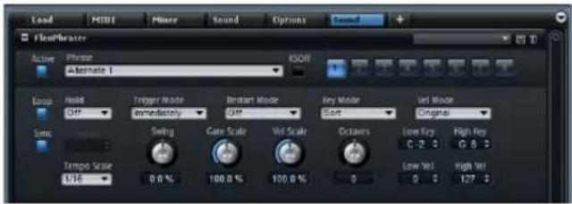
HALion features an arpeggio and phrase player: the so-called FlexPhraser. You can select from a great variety of phrases that suit a wide range of musical instruments and styles. Depending on the selected phrase, the FlexPhraser uses your live playing to modify the phrase in real-time. This allows you, for instance, to re-harmonize phrases by playing different chords.
FlexPhraser presets
In the top right of the FlexPhraser editor, you can load and save presets for the FlexPhraser. In addition to the selected phrase, these presets also contain the performance settings of the FlexPhraser, such as Tempo, Tempo Scale, Loop, Swing, etc.
Presets can only be saved and loaded for phrases, not for sliced loops.
Loading Phrases for the FlexPhraser
The phrases are sorted into subfolders, according to the type of instrument. Each instrument subfolder contains phrases of different musical styles.
To load a phrase, proceed as follows:
- At the top of the FlexPhraser, click in the Phrase field.
- On the pop-up menu, open the submenu for the instrument, and select the phrase you want to load.
In general, you can apply any phrase to any type of instrument. However, a phrase for guitar might not be suitable for use with a piano, for example.
Phrase Playback Types
HALion features a huge amount of phrase types organized in categorized submenus such as Classic Arp, Synth Seq, Chord Seq, Bass, and so on. Each folder can contain several submenus containing phrases categorized according to functional descriptions or musical styles.
The Construction Sets submenu contains phrases especially made for HALion's instrument layers. These phrases use key switches to switch between different playing styles, to increase the realism of your performance.
The phrases that can be found in the various other categories use a number of different playback types to allow phrase-specific user interaction while playing:
Option Description
| Playback of a drum pattern | Pressing any note triggers the same rhythm pattern. |
| Playback only of the played notes | The phrase is played back using only the played note and its octave notes. |
| Playback of a programmed sequence according to the played chord | When you press only one note, the phrase is played back using the programmed sequence — which means that notes other than the ones you play are triggered. When you are adding notes to those already held, the sequence changes accordingly — for example, the phrase plays back according to the chord you play. |
Mute
Activate the Mute button to silence the phrase temporarily. The phrase still plays in the background. When you deactivate Mute, playback resumes immediately.
KS Off (Key Switches off)
Construction Set phrases that make use of key switches and noises (fret noises for guitar phrases, for example) usually work only with programs for the same type of instrument. Programs without key switches and noises play back such events as normal notes that do not fit to the rest of the phrase. To avoid the playback of key switches and noises, activate the KS Off option.
⇒ As this option filters out any note events that do not transpose with your playing, drum phrases do not work when this option is activated.
Loop
When this option is activated, the phrase plays in a loop.
Hold
Here, you can make the following settings:
Option Description
Off The phrase changes immediately when releasing a key. The phrase stops immediately when releasing all keys.
On The phrase plays to the end even when the keys are released. When the Loop option is activated, the phrase plays continuously in a cycle.
Gated The phrase starts playback with the first key being played. It plays silently in the background even when the keys are released, and resumes playback at the current position when you press any of the keys again. This way, you can gate the playback of the phrase.
Trigger Mode
The Trigger Mode defines when the FlexPhraser scans for new keys you play on the keyboard.
The following options are available:
Option Description
Immediately The FlexPhraser scans for new keys all the time. The phrase changes immediately in reaction to your playing.
Next Beat The FlexPhraser scans for new keys at every new beat. The phrase changes in reaction to your playing on each new beat.
Next Measure The FlexPhraser scans for new keys at the start of new measures. The phrase changes in reaction to your playing on each new measure.
Restart Mode
Here, you can make the following settings:
Option Description
Off The phrase runs continuously and does not restart at chord or note changes.
New Chord Select this to restart the phrase on new chords. However, the phrase does not restart upon notes that are played legato, for example, if you play additional notes to a chord you are holding already.
New Note Select this to restart the phrase with each new note you play. Here, the phrase does restart also upon notes that are played legato.
Sync to Host Select this to align the phrase with the beats and measures of your host application. The phrase aligns to the beats and measures each time you start the transport.
Key Mode
This option defines if the order of the notes, as played on the keyboard, affects the playback of the phrase.
The following options are available:
Option Description
Sort The notes play in the order of the selected pattern. The chronological order is without influence.
As Played The notes play in the chronological order as you played them on the keyboard.
Direct The phrase itself does not create any note events, but controller events only. You hear the notes you play plus any controller events of the phrase, such as pitchbend, volume, pan, etc. Not all phrases contain controller data. Consult the documentation of the phrase to see if it does.
Vel Mode
This option specifies how the velocity of the notes you play affects the notes of the phrase.
The following options are available:
Option Description
Original The notes of the phrase play with the velocity saved with the phrase.
As Played The notes of the phrase play with the velocity you are playing on the keyboard.
Original + As Played The phrase velocity is determined by the combination of the velocity saved with the phrase and the velocity of your playing.
Sync
To synchronize the phrase to the tempo of your host application, activate Sync.
In addition, you can set the Restart mode to "Sync to Host". This aligns the phrase with the beats and measures of your host application.
Tempo
When Sync is deactivated, use the Tempo control to set the internal playback speed of the FlexPhraser. The playback speed of the phrase is specified in Beats per Minute (BPM). In addition, Tempo Scale gives you further control over the playback speed. The Tempo control is not available when Sync is activated.
Tempo Scale
This parameter defines the rate at which notes are triggered, in other words, the speed at which the phrase is running. You can specify a value in fractions of beats. You can also set dotted and triplet note values.
When the Tempo parameter is 1/16 and you set this value to 1/8, for example, the speed is cut to half. When you set it to 1/32, the speed is doubled. Other values increase or decrease the speed accordingly.
Swing
Use this parameter to shift the timing of notes on even numbered beats. This way, the phrase gets a swing feeling. Negative values shift the timing backward, and the notes are played earlier. Positive values shift the timing forward, and the notes are played later.
Gate Scale
This parameter allows you to shorten or lengthen the notes of the phrase. At a value of 100 %, the notes play with their original gate length.
Vel Scale
This parameter allows you to raise or lower the note-on velocities of the phrase. At a value of 100 %, the notes are played with their original velocity.
Octaves
This setting extends the phrase playback to include higher or lower octaves. Positive settings extend the playback to higher and negative settings to lower octaves. For example, a value of +1 first plays the phrase in the octave range you originally played. Then, it repeats the phrase one octave higher.
Play Range
You can use the Play Range parameters to determine which keys and velocities trigger the phrase playback.
Low Key
This defines the lowest key that triggers the phrase.
High Key
This defines the highest key that triggers the phrase.
Low Vel
This defines the lowest velocity that triggers the phrase.
High Vel
This defines the highest velocity that triggers the phrase.
Working with FlexPhraser Variations
For each FlexPhraser module that you add, you can set up up to 8 different variations of phrases. You can switch between them with the variation buttons at the top right of the FlexPhraser. You can also remote-control the Variation buttons using HALion's trigger pads. This also gives you the possibility to switch between variations by playing the trigger keys assigned to the trigger pads.
To avoid that the variation switches in the middle of a beat or measure, use the trigger modes "Next Beat" or "Next Measure".
Creating Variations
You can create variations either by starting from scratch or by copying an existing one.
To start from scratch, proceed as follows:
- Click one of the 8 variation buttons at the top right of the FlexPhraser.
- Assign a phrase and edit the FlexPhraser settings. The variation is saved and can be recalled by clicking the Variation button.
To copy an existing variation, proceed as follows:
- Right-click the variation button for the variation that you want to copy and select "Copy FlexPhraser Variation".
- Right-click the variation button to which you want to paste the variation and select "Paste FlexPhraser Variation".
⇒ The parameters Loop, Sync, Hold, Trigger Mode, Restart Mode, Key Mode, Vel Mode, Low/High Key, and Low/High Vel are not part of the variations. You set them up only once for each inserted FlexPhraser module.
Switching Variations with the Trigger Pads
You can switch between variations using the trigger pads (see "Switching between FlexPhraser Variations" on page 145).
The Trigger Pads
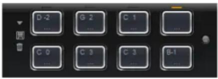
You can use the trigger pads to trigger single notes or whole chords and to switch between FlexPhraser variations. Many of the programs that come with HALion make use of the trigger pads:
- Blue pads have single notes or whole chords assigned.
- The line above the pad turns orange when the pad switches between FlexPhraser variations.
- To trigger a pad with your mouse, click the corresponding pad.
Assigning Trigger Notes to Pads
You can assign a MIDI note to a pad and trigger the pad by playing this note.
To define the note, you have the following options:
- Right-click a pad, open the "Assign Trigger Note" submenu, and from the further submenus, select the octave, and note that you want to assign.
- Open the context menu for a pad, select "Learn Trigger Note", and play the note on your MIDI keyboard (or click a key on the internal keyboard).
The name of the assigned trigger note is displayed in the top left corner of the pad.
On the internal keyboard, keys that serve as trigger notes are shown in blue. These keys do not play sounds, but trigger the corresponding pads instead.
- To remove a trigger note from a pad, right-click the pad and select "Forget Trigger Note".
Using Default Trigger Note Settings
By default, the assigned trigger notes are stored with each program to allow for maximum flexibility. However, you may want to keep a fixed set of trigger notes to reflect an existing hardware setup.
To be able to use default trigger note settings, you have to save them first:
- To specify a global set of trigger notes, set the trigger notes for all pads, right-click a pad, and from the context menu, select "Save Trigger Notes as Default".
Now you can activate the "Use Default Trigger Notes" option:
- Right-click a pad and select "Use Default Trigger Notes".
Changing programs or multi-programs does not change the trigger notes anymore.
When you deactivate this option, the last set of trigger notes remains active. To return to the trigger notes that were saved with the program, reload the program.
Naming a Pad
To indicate the functionality of a pad, you can enter a name. Proceed as follows:
- Right-click the pad, and on the context menu, select "Rename Pad".
- Enter the name.
- Press [Enter] to confirm the name.
Triggering Chords or Single Notes
To trigger a chord or a single note with a pad, you first need to define the chord or note:
- Right-click a pad.
- On the context menu, select "Snapshot Chord".
The pad starts blinking to indicate that it is in Learn mode. - Play a chord or a single note.
The keys belonging to the chord are highlighted on the internal keyboard. - To accept the chord or note, click the pad that is blinking.
The pad turns blue to indicate that a chord or note is assigned.
Triggering the pad now plays the chord or note.
To use the pads for switching between expressions, select "Snapshot Chord" on the context menu and play the corresponding key switch.
If you define a chord that also contains a key switch, you can trigger the chord with a specific instrument expression.
⇒ If you add keys to a chord that also work as trigger notes, they trigger the underlying MIDI note instead of the trigger note.
- To clear the chord or note from a pad, right-click the trigger pad and select "Clear Chord".
Switching between FlexPhraser Variations
You can use the trigger pads to switch between Flex-Phraser variations. For more information, see “Working with FlexPhraser Variations” on page 143.
Proceed as follows:
- Right-click the trigger pad you want to use for switching to the selected FlexPhraser variations.
- On the menu, select "Snapshot FlexPhrasers".
The line above the pad turns orange to indicate that a FlexPhraser snapshot is assigned. - When you trigger the pad, it switches to the variations that were selected when you made the snapshot.
Instead of storing the variation settings themselves, the trigger pad stores only which variations were selected when you made the snapshot. This allows you to change settings of variations even after you made the snapshot.
When layers are replaced or added, you need to take the FlexPhraser snapshot again. - To clear the FlexPhraser snapshot, right-click the trigger pad and select "Clear FlexPhrasers".
Bypassing the Trigger Pads
You can bypass the whole Trigger Pads editor. This deactivates any functionality assigned to the trigger pads.
- To bypass the Trigger Pads editor, click the Bypass Pads button to the right of the trigger pads.
The bypass button lights up to indicate that the trigger pads are deactivated.
Using Pad Presets
Presets for the trigger pads can be managed via the controls in the top left corner of the Trigger Pads editor.
⇒ Pad presets save trigger notes and chord snapshots, but not FlexPhraser snapshots. As a result, you can exchange trigger notes and chords by loading presets without loosing your FlexPhraser snapshots.
Mono Envelope

This MIDI module triggers a monophonic multi-segment envelope, which you can use as a modulation source in the modulation matrix of a zone. In this context, monophonic means that the envelope is not played back per zone. Instead, it is played back only once for each program or layer it belongs to. You can set up a condition for triggering and releasing the envelope. By default, this envelope is bipolar.
For a complete description on how to edit the envelope graphically, please refer to "The Envelope Section" on page 85.
Envelope Mode
You can select one of three envelope modes to specify how the envelope is played back each time you trigger it.
Option Description
Sustain The envelope plays from the first node to its sustain. The sustain level is held for as long as you play the note. When you release the note, the envelope continues with the stages following the sustain. This mode is ideal for looped samples.
Loop The envelope starts playback from the first node to the loop nodes. The loop is repeated for as long as the key is held. The envelope plays the stages following the sustain when you release the note. This mode is ideal for adding motion to the sustain of the envelope.
Option Description
| One Shot | The envelope is played from the first to the last node, even if you release the key. The envelope has no sustain stage. This mode is ideal for drum samples. |
Trigger Mode
On the Trigger pop-up menu below the envelope display, you can set the condition for triggering the envelope.
Option Description
| First Note | Select this mode to trigger the envelope with the first note that you play. Any following notes you play legato do not trigger the envelope. |
| Each Note Select this mode to trigger the envelope with each note you play. The envelope plays back from its attack each time you press a key. | |
Release Mode
On the Release pop-up menu below the envelope display, you can set the condition for releasing the envelope.
Option Description
| First Note Select this mode to release the envelope with the first note you release. | |
| Last Note | Select this mode to release the envelope with the last note you release. |
Level Velocity
Use this parameter to adjust how velocity affects the level of the envelope. The level of the envelope depends on two factors: the setting of this parameter and how hard you hit a key. Positive values increase and negative values decrease the level of the envelope the harder you hit a key.
Level Velocity Curve
You can select one of eight curves to specify how the incoming velocity translates to the level of the envelope. The characteristic of each curve is displayed by a small icon.
Time Velocity
Use this parameter to adjust the influence of velocity on the times of the envelope. Positive values decrease the times for higher velocity values. Negative values increase the times for higher velocity values.
Segments
On the Segments pop-up menu, you can specify which stages of the envelope are affected by the Time Velocity parameter.
Option Description
A The velocity affects the attack time only.
A + D The velocity affects all times until the sustain.
D The velocity affects all times until the sustain but without the attack.
A + R The velocity affects the attack and the release times.
All The velocity affects all times.
Key Follow, Center Key, and KeyF Rel (Key Follow Release)
With the Key Follow and KeyF Rel parameters, you can scale the envelope times across the keyboard. Key Follow scales all times before the sustain node. KeyF Rel scales all times after the sustain node (that is to say the release of the envelope). You can specify a center key that is used as the central position for the Key Follow and KeyF Rel functions. The envelope times depend on the keyboard range in which the note is played and on the corresponding Key Follow setting: Positive values decrease the times for notes above and increase the times for notes below the Center Key; the envelope becomes faster the higher the note you play. Negative values increase the times for notes above and decrease the times for notes below the Center Key; the envelope becomes slower the higher the note you play.
Mono LFO
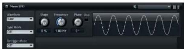
HALion allows you to add monophonic LFOs as MIDI modules to the program. An LFO module can be used for an entire program, or for specific layers. In this context, monophonic means that these LFOs are only calculated once and feed multiple voices at the same time. A pitch modulation controlled by the modulation wheel is a typical example where one LFO controls the vibrato for all voices. Monophonic LFOs appear as sources in the modulation matrix of the zones contained in a layer or program.
LFO Presets
HALion comes with LFO presets that you can use as a starting point for sound editing. For detailed information on preset handling, see "Working with Presets" on page 51.
LFO Parameters
LFO Waveform Types
Use the Waveform pop-up menu to select the basic type of waveform and use the Shape control to change the characteristic of the waveform.
Option Description
| Sine This produces smooth modulation, suitable for vibrato or tremolo. The Shape parameter adds additional harmonics to the waveform. | |
| Triangle | This is similar in character to Sine. The waveform periodically ramps up and down. The Shape parameter continuously changes the triangle waveform to a trapezoid. |
| Saw This produces a ramp cycle. The Shape parameter continuously changes the waveform from ramp down to triangle to ramp up. | |
| Pulse This produces stepped modulation, where the modulation switches abruptly between two values. The Shape parameter continuously changes the ratio between the high and low state of the waveform. Set Shape to 50% to produce a square wave. | |
| Ramp | This is similar to the Saw waveform. Turning up the Shape control increases the length of the silence between ramps. |
Option Description
Log Logarithmic curve. The Shape parameter continuously changes the logarithmic curvature from negative to positive.
S & H 1 This produces randomly stepped modulation. The Shape parameter puts ramps between the steps and changes the S&H into a smooth random signal when fully turned right
S & H 2 This is similar to S & H 1. The steps are alternating between random high and low values. Shape puts ramps between the steps and changes the S & H into a smooth random signal when fully turned right.
Frequency
This controls the frequency of the modulation, that is to say the "speed" of the LFO. When Sync Mode is active, the frequency is set in fractions of beats, or number of steps of the Step Modulator.
Phase
Sets the initial phase of the waveform when the LFO is re-triggered.
Rnd (Random)
When this button is activated, each note starts with a randomized start phase. The Phase control is deactivated.
Sync Mode
You can sync the LFO either to the tempo of the host application or to HALion's Step Modulator. The behavior of the Frequency parameter depends on the selected option:
Option Description
| Off | Select this to adjust the speed of the modulation in Hertz. |
| Tempo + Retrig | Select this to adjust the speed of the modulation in fractions of beats (1/4, 1/8, etc.). You can also set dotted and triplet note values. The restart behavior of the LFO depends on the Retrigger setting. |
| Tempo + Beat | Select this to adjust the speed of the modulation in fractions of beats. You can also set dotted and triplet note values. The LFO restarts with the transport of the host and lines up to the beats of the project. The Retrigger setting is not taken into account. |
Retrigger Mode
Determines whether the LFO is restarted when a note is triggered. When Retrigger is set to First Note or Each Note, the waveform starts at the position specified by the Phase parameter.
Option Description
Off The LFO is running freely.
First Note The LFO restarts when a note is triggered and no other notes are already held.
Each Note The LFO restarts each time a note is triggered.
LFO Bypass
To hear the sound without any LFO modulation, click the Bypass button (the speaker icon) in the title bar of the section. This deactivates all LFOs.
MegaTrig
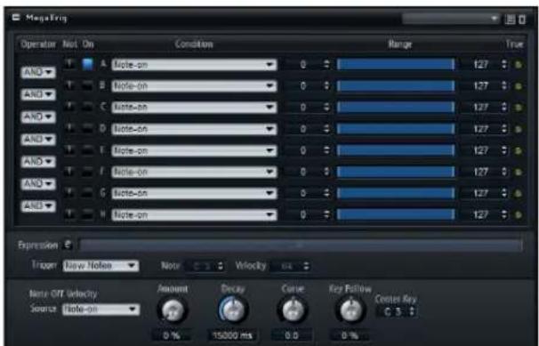
The MegaTrig module is used for controlling playing styles and articulations and for triggering release samples and instrument noises.
Setting up Conditions
By setting up conditions, you can determine which zone is triggered. For each condition, you can specify an event and range.
Proceed as follows:
-
In the Program Tree, insert the MegaTrig module at the position where you want to apply the playback rules. This can be the program or one of its layers. Any zones within the program or layer are affected, too.
-
Open the editor of the MegaTrig module.
-
On the pop-up menu for the first condition, select an event.
-
Activate the condition by clicking the On button to the left of the menu.
-
Use the faders and value fields to the right to adjust the minimum and maximum value of the range.
-
To set up more conditions, repeat these steps for additional rows.
-
Select the logical operations, AND or OR, from the menu to the left of the conditions. To invert a condition, activate the NOT operation (the button with the exclamation mark).
The Expression field displays the conditions and logical operations you set.
- Set the Trigger option to determine which notes are triggered when the expression becomes TRUE.
⇒ The operation AND is executed before the operation OR.
Setting up the Expression Manually
Instead of using the AND/OR menus and NOT buttons, you can enter the expression manually. This way, you can also influence the execution order of the expression.
Proceed as follows:
-
Click the edit button next to the Expression field.
-
Type in the conditions and logical operations, for example A AND B OR C.
Instead of AND, OR, and NOT, you can also type the letters &, | and !.
- Put in parentheses to specify the execution order, for example A AND (B OR C).
⇒ If you edit the expression manually, the AND/OR menus and the NOT and On buttons are not available.
Selecting a Condition
You can combine up to 8 conditions into an expression using logical operations. For example, the expression "Note-on AND Sustain On" is TRUE when you play notes while holding the sustain pedal down. Any assigned zones only play back if the whole expression is TRUE.
For each of the conditions, you can make the following settings:
Option Description
| Condition You select the event for the condition from the Condition pop-up menu. The condition is TRUE when the event is of the right type and within the specified range. | |
| On | Click this button to activate the corresponding condition. |
| Min Use the fader and value field to adjust the minimum value of the range. This is the lowest possible value for a TRUE condition. | |
| Max Use the fader and value field to adjust the maximum value of the range. This is the highest possible value for a TRUE condition. | |
| AND Combines two conditions logically. The expression is TRUE if both conditions are TRUE. | |
| OR Combines two conditions logically. The expression is TRUE if one of the conditions is TRUE. | |
| NOT Activate this to invert the condition. A condition that was previously TRUE becomes FALSE, and vice versa. | |
| Expression | Displays how the logical operators and conditions are executed. Click the "e" button to edit the Expression manually. Put in parentheses to influence the execution order. |
The following options are available on the Condition pop-up menu:
Option Description
| Note-on The condition is TRUE when a key is pressed. You can specify a key range for this event. | |
| Note-off The condition is TRUE when a note is released and a matching note-on event was received. This includes notes that are released by lifting the sustain pedal. You can specify a key range for this event.This option allows you to avoid triggering the wrong release samples after switching between articulations of an instrument. Note that for this to work, the layers of the note-on and note-off samples must reside in the same layer of the corresponding Key Switch MegaTrig module. | |
| Forced Note-off | The condition is TRUE when a note is released. Forced means that a matching note-on event is not needed. In other words, the note-off event always passes through. This includes notes that are released by lifting the sustain pedal. You can specify a key range for the note-off events. |
Option Description
| Key Up The condition is TRUE when a note is released even when the sustain pedal is pressed. This condition uses the full range of the keyboard. | |
| Sustain On The condition is TRUE when the sustain pedal is pressed. | |
| Sustain Off The condition is TRUE when the sustain pedal is released. | |
| Key Switch The condition is TRUE when a note in the specified note range was pressed. Multiple Key Switch assignments across different layers of the program work like radio buttons, so only one Key Switch assignment can be active at a time. By default, the Key Switch assignment with the lowest key is TRUE.Note: If you want the Key Switch assignments across different layers to work individually, activate the Individual MegaTrig Management of the corresponding layers. For example, this can be necessary when two programs with Key Switches are copied together into one program. | |
| Key Range 1st The condition is TRUE beginning with the 1st note that is held within the specified note range. | |
| Key Range 2nd | The condition is TRUE beginning with the 2nd note that is held within the specified note range |
| Key Toggle | This condition toggles between TRUE and FALSE each time you hit a key within the specified note range. By default, the condition is TRUE. If you toggle the condition from 0, the odd numbers (1, 3, 5, 7, and so on) are FALSE and the even numbers (2, 4, 6, 8, and so on) are TRUE. |
| Velocity | The condition is TRUE when the received velocity is within the specified velocity range. |
| Playing Speed | The condition is TRUE when the time between successive notes is within the specified range. |
| Legato | The condition is TRUE when you play notes legato. You can specify a key range for the legato played notes. |
| Retrigger | The condition is TRUE when a note is retriggered. You can specify a key range for the retriggered note.Note that this condition must always be combined with Note-On and that Mono and Retrigger must be activated in the Voice Management of the corresponding layer or program. |
| Interval | The condition is TRUE when the interval between successively played notes is within the specified range. |
| Note Count | The condition is TRUE when the number of played notes is within the specified range. |
| Lowest Note | The range control specifies the order of the notes in a chord from low to high. The condition is TRUE when the played notes match the specified range. For example, a range from 0 to 1 means the first and second lowest note play and all other notes are filtered out. |
| Highest Note | The range control specifies the order of the notes in a chord from high to low. The condition is TRUE when the played notes match the specified range. For example, a range from 0 to 1 means the first and second highest note play and all other notes are filtered out. |
Option Description
| MIDI Controller | The condition is TRUE when the position of the controller is within the specified range. |
| Quick Controls | The condition is TRUE when the Quick Control is within the specified range. |
| Random Produces | a random value between 0 and 100 for each note that is played. The condition is TRUE, when the random value is within the specified range. |
Two MIDI note events combined by an AND operation can never turn TRUE. For example, the expressions "Note-on AND Note-off", or "Note-on AND Key up", or "Note-off AND Key up" can never be TRUE.
When using several MegaTrig modules, the random value is the same across all MegaTrig modules, if you select the Random option in the same row. By setting the ranges so they do not overlap, you can switch randomly between the corresponding layers.
Trigger Options
In addition to the expressions, you can specify the Trigger options.
The following options are available:
Option Description
New Notes When the expression is TRUE, only new notes trigger the zones.
Held Note When the expression is TRUE, the currently held notes and any new notes trigger the zones.
Fixed Note When the expression is TRUE, a single note is sent. When Fixed Note is selected, the Note and Velocity parameters become available. Use them to determine the note to be sent. For example, to trigger the pedal noise of a grand piano, select the condition Sustain On and set Trigger to Fixed Note. You can adjust the note and velocity of the fixed note that is triggered. The Held Notes and New Notes options trigger the notes as you played them on the keyboard.
Note-Off Velocity
Below the Trigger options, the parameters to control the velocity of note-off samples are located. This includes any sample selection through velocity mapping of the note-off samples. The velocity may also have an effect on the level of the note-off samples, as programmed in the zone.
The following parameters are available:
| Option Description | |
| Source | Here, you can select if the velocity that is sent to the release samples is taken from the note-on or the note-off event. |
| Velocity Amount | Allows you to adjust how much the selected option affects the velocity of the note-off sample. This includes any sample selection through the velocity mapping of the release samples.Note that the velocity may also have an effect on the volume of the sample, as programmed in the zone. |
| Decay Time | Depending on the time you set, the velocity of the note-off sample is reduced the longer you hold a key. |
| Decay Curve Sets the curvature of the note-off velocity decay. Use positive values for an outward shaped curve and negative values for an inward shaped curve. Without changing the overall decay time, an outward shaped curve reduces the note-off velocity faster and an inward shaped curve reduces it slower. | |
| Decay Key Follow | Scales the decay time across the keyboard. You can set a center key that is used as the central position for the Key Follow function. For example, set this parameter to positive values to decrease the decay time for notes above and increase it for notes below the center key. |
| Decay Center Key | Specifies the note number that is used as a central position for the key follow function of the Decay Time. The range extends from C-2 to G8. |
Layer Alternate
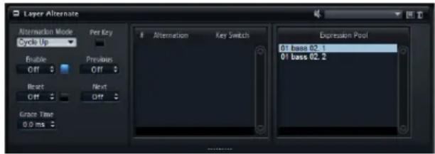
You can use this module to switch between different layers automatically. This is useful for alternating between the up and down bows of a string instrument or the left and right hand of drum strokes, for example.
To alternate playback between different layers, proceed as follows:
- Insert the Layer Alternate module above the layers between which you want to switch.
- Open the editor for the module and drag the layers from the Expression Pool into the Alternation List in the order you want to switch them.
You can rearrange the order of the list using drag and drop.
- Select the Alternation Mode and start playback.
Layer Alternate always switches the playback between layers. For switching between single zones, use Variation Groups instead, see "The Variation Groups Section" on page 71.
To play back a specific expression, turn off the Enable button to stop any automatic alternation and select the expression in the Alternation list.
Expression Pool
This list shows the available layers that can be alternated.
Alternation List
To alternate the layers, drag and drop them from the Expression Pool to this list. You can change the order of the listed layers by dragging them to a new position. The layer that is currently played back is highlighted. To remove an expression from the Alternation list, use the context menu.
Using Key Switches
In some cases, it is useful to switch to a particular layer, regardless of the current position in the Alternation list. To make this possible, you can specify a key switch per layer. As soon as the key switch note is played, the alternation list jumps to the corresponding layer. The alternation then continues from that position.
- To set the key switch, type in the note, as text or number, in the key switch column of the Alternation List.
Alternation Mode
The process of alternating between layers is determined by the following options:
Mode Description
Cycle Up Select this mode to cycle through the layers in descending order.
Cycle Down Select this mode to cycle through the layers in ascending order.
Random Select this mode to alternate the layers randomly with each note you play.
Exclusive Random Select this mode to alternate the layers randomly, but without repetitions.
Per Key
Select this option to apply the alternation for each MIDI key separately. When this is switched off, the alternation is applied globally across the whole keyboard, so that any key you play advances the alternation sequence.
Enable
Here, you can specify the MIDI key that starts and stops the alternation sequence. This key will be used exclusively for this function and will not trigger any notes.
When set to Off, playback remains on the selected layer.
Previous/Next
Here, you can specify the MIDI key that switches to the previous/next expression.
Reset
Here, you can specify the MIDI key that resets the Alternation sequence.
Grace Time
The Grace Time parameter sets a minimum time between two steps, which allows you to play chords, for example. (Otherwise, each note of the chord will play with a different layer.)
Key Switch Alternate
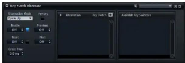
Use this module to switch automatically between different layers that are using MegaTrig key switches to define whether they are played or not.
To alternate the playback between different key switches, proceed as follows:
- Insert the Key Switch Alternate module above the layers that contain the MegaTrig modules with key switch settings.
- Open the module editor and drag and drop the key switches from the Available Key Switches list to the Alternation List in the order you want them to alternate. You can rearrange the order of the list using drag and drop.
- Select the Alternation Mode and start playback.
This MIDI module is provided for compatibility with HALion 3 programs, because in HALion 3, the alternation of layers was realized using key switches. When using HALion 4, no additional MegaTrig modules with key switch settings are necessary. Instead of using Key Switch Alternate, you can use the Layer Alternate module.
Available Key Switches
This list shows the currently available key switches that can be used to control an alternation. To create new alterations, drag a key switch from this list to the Alternation list. Note however, that there is no direct relation between the Available Key Switch list and the Alternation list and once created, an alternation can be renamed and assigned a note.
Alternation List
To alternate key switches, drag and drop them from the list of available key switches to this list. Depending on the selected alternation mode, the triggered key switches alternate in the order they are listed or randomly. You can change the order of the listed key switches by dragging them to another position. The key switch that is currently triggered is highlighted. To remove a key switch from the Alternation list, use the context menu for the selected key switch.
To trigger a specific key switch, turn off the Enable button to stop any automatic alternation and select the key switch in the Alternation list.
Adding New Alternations
Normally you add alternations by dragging existing key switches from the Available Key Switches list. However, it is also possible to create new alternations from scratch. Proceed as follows:
- Click the "+" button above the Alternation list.
- An new alternation is added to the list.
- Specify the name of the alternation.
- Specify the key switch note to be sent.
Naming Alternations
The available key switches come with an additional name that is derived from the layer name of the MegaTrig parent layer.
Alternation Mode, Per Key, Reset, and Enable
These options are the same as for the Layer Alternate module, see "Layer Alternate" on page 150.
Grace Time
The Grace Time sets a minimum time between two steps, which allows you to play chords, for example. Otherwise, each note of the chord plays with a different layer.
Key Switch Remote
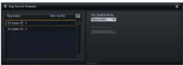
The Key Switch Remote module allows you to remote-control key switches that are used within the current parent layer.
The expression list shows all available layers. If a layer contains a MegaTrig module set to "Key Switch", the specified key is displayed in the Key/Active column.
Key Switch Mode
Here you can define if you want to use the original key switches as set in the MegaTrig modules, remap them to other keys, or to use a MIDI controller instead.
No matter which mode you select, the original key switch assignments still work. This is important for phrases for the FlexPhraser module that make use of the original key switches. The last key switch that is received always has priority.
Key Switch
When Key Switch is selected, the original key switch assignments are used to switch to an expression. The keys are displayed in the list and cannot be edited.
Remapped
When Remapped is selected, you can transpose the original key switch assignments to the playable range of your MIDI keyboard.
To do so, enter the MIDI note you want the expression to be reassigned to.
You can also transpose multiple key switches at the same time. Press [Shift] and drag one of the text faders for the key switch you want to change.
⇒ The MIDI notes you use for key switches can no longer be used to trigger samples.
MIDI Controller
The MIDI Controller mode allows you to define a MIDI controller that remote-controls the original key switches. In this mode the list does not show any MIDI note names, but checkboxes that allow you to specify the expressions you can switch to. Inactive expressions cannot be addressed.
- To assign a MIDI controller, select it from the MIDI Controller pop-up menu.
Refreshing the Expression List
When adding, moving, or removing layers with key switches after the Key Switch Remote module has been set up, it can become necessary to refresh the Expression list. To do so, click the Refresh button in the title bar.
MIDI Randomizer

The MIDI Randomizer module allows you to trigger notes randomly. These notes can be created by modifying the original notes and/or velocity values using an adjustable deviation amount, or within a completely independent range that can be set for key and/or velocity. You can also limit the input range for incoming MIDI notes to decide on which notes the module reacts.
In the Input section to the left, you can make the following settings:
Option Description
Low Key/High Key These values define which incoming notes are used by the Randomizer to create random notes.
Low Vel/High Vel These values define the velocity range that is used by the Randomizer to create random notes.
In the Output section to the right, there are two rows of settings.
The upper row offers the following parameters:
Option Description
Active Activate this switch if you want the Randomizer to create notes within a certain key range.
Spread If you activate this, you can use the input values and vary them randomly. Use the Amount parameter to define how much the random notes can diverge from the original keys. By deactivating this option, you can create notes within a specific key range, which is set using the Low Key/High Key value fields.
The lower row offers the following parameters:
Option Description
Active Activate this switch if you want the Randomizer to create notes within a certain velocity range.
Spread If you activate this, you can use the input values and vary them randomly. Use the Amount parameter to define how much the random notes can diverge from the original keys. By deactivating this option, you can create notes within a specific velocity range, which is set using the Low Vel/High Vel value fields.
True Pedaling
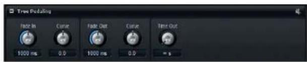
This MIDI module produces a modulation signal from the sustain pedal, which you can use to simulate true pedaling of grand pianos. Instead of switching between two layers, this module allows you to crossfade between layers when you press or lift the sustain pedal, which produces a more realistic sound.
To set up a crossfade between two layers, proceed as follows:
- Set the Level parameter of the zones with the note-on samples to the default level (0 dB).
- Set the Level parameter of the zones with the sustain resonance samples to the minimum setting.
- In the modulation matrix, select the True Pedaling module as the modulation source and assign it to the modulation destination Level.
- To bring the crossfade into effect, modulate the level of the note-on samples in negative direction and the level of the sustain resonance samples in positive direction.
The following settings are available:
| Option Description | |
| Fade In Time | Specifies the fade in time of the modulation signal, when you press the sustain pedal. |
| Fade In Curve | Sets the curvature of the fade in. Use negative values for an outward shaped curve and positive values for an inward shaped curve. |
| Fade Out Time | Specifies the fade out time of the modulation signal, when you lift the sustain pedal. |
| Fade Out Curve | Sets the curvature of the fade out. Use positive values for an outward shaped curve and negative values for an inward shaped curve. |
| Time Out | On acoustic pianos, pressing the sustain pedal after a certain time has little to no effect. You can achieve the same effect by using this parameter: Pressing the sustain pedal after the time you set here will have no effect. Any resonance samples that have been triggered, but were not faded in, are released. |
- Once the modulation is set up, the resonance samples are triggered with each note, but you do not hear them until you press the sustain pedal.
CC Mapper
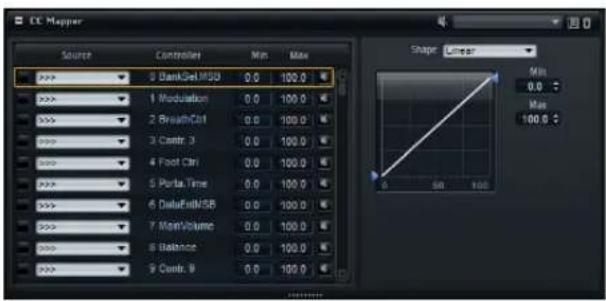
The CC Mapper allows you to map MIDI controllers to other MIDI controllers before they are passed on to the following layers and zones. You can also use it to transform incoming values using curves.
MIDI controllers, Aftertouch and Pitch Bend can be mapped freely to all MIDI controllers, Aftertouch, Pitch Bend, and the eight global controllers Contr. A – Contr. H. Velocity and the global controllers themselves can only be mapped to Contr. A – Contr. H.
To map a MIDI Controller to another MIDI Controller (or Aftertouch or Pitchbend), click in the Source column for the MIDI controller and select a new item from the list.
→ Velocity can only be used as Source for the global controllers Contr. A – Contr. H.
Contr. A – Contr. H allow you to change the MIDI controller assignment via a single setting in the CC Mapper instead of changing the modulation matrix assignments of the single zones separately, for example. This can be achieved by assigning them in the modulation matrix and mapping a MIDI controller or velocity to them using the CC Mapper.
Source
Here you can specify the source controller that is to be remapped. By default, no remapping is processed and all controllers are passed through.
Controller
This column lists the available destination controllers.
Bypass
Click the bypass button for a controller to deactivate the remapping for it.
Min
This defines the minimum value to be sent.
Max
This defines the maximum value to be sent.
Using the Curve and Range Editor
You can set up a curve and range for each remapped source. The curve and range editor displays the settings of the selected source controller, marked by an orange frame. To select a different source, click the button to the left of it.
The Curve editor allows you to set up a transformation function. You can use one of the provided curve types like linear, logarithmic, dB, etc., or create your own custom curve. By setting the minimum and maximum values, the function output stays within the specified range only. The values correspond to the Min and Max columns in the list on the left.
To set up your own curve, select the Custom preset. This allows for the following editing:
- You can double-click in the editor to insert a new node. Double-click on a node to delete it.
- Drag the nodes to new positions to adjust the basic shape of the curve.
- Drag the lines between the nodes up or down to change the curvature.
Velocity Curve
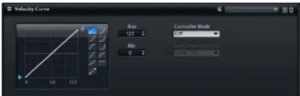
The Velocity Curve module allows you to map incoming velocity values to different output values using an adjustable curve. You can also use this module to limit the output velocity range or use its side-chain controller input to control the effect of the curve using a MIDI controller.
Curve display
In the Curve display section to the left, you can use one of 10 preconfigured curve types, or create a custom curve. To select a curve type, click on one of the buttons to the right of the curve display.
When the Custom curve is selected, you can make the following settings:
- To insert a new node, double-click in the editor. Double-click on a node to delete it.
- To adjust the basic shape of the curve, drag the nodes to another position.
- To change the curvature, drag the lines between the nodes up or down.
Minimum and Maximum
With the minimum and maximum values, you can specify the output velocity. The curve is compressed accordingly.
Controller Mode
Sometimes it is useful to control the effect of the curve dynamically. For that purpose, you can use a definable side-chain controller, either in Switch or Continuous mode.
Off
When Controller Mode is set to Off, the curve is applied at 100 %. The side-chain controller cannot be used.
Switch
In this mode, the velocity curve is only applied when the side-chain controller sends a value higher than 64. This allows you to use a foot switch to activate or deactivate the influence of the velocity curve, for example.
Continuous
In this mode, the incoming side-chain controller value is used to scale the influence of the velocity curve. When set to 0, the curve has no effect, when set to 127, the curve is applied at 100%.
Side-Chain Controller
Here, you can specify which MIDI Controller is used to control the effect of the velocity curve.
Tuning Scale
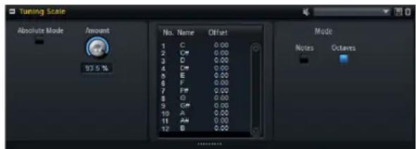
The Tuning Scale MIDI module comes with many ready-to-use tuning scale presets. These can be loaded and saved using the regular editing methods, see the chapter "Working with Presets" on page 51.
The most commonly used scale in western music is the equal temperament, where adjacent notes have an equal distance of 100 cents. Therefore, the Equal Temperament preset is loaded by default. In the Concert Grand scale, the upper notes are tuned increasingly higher and the lower notes are tuned increasingly lower. Use this for the most natural sound of the pianos. Furthermore, many well-known traditional tuning scales in different keys are available, like the Well Tempered scale or the Kirnberger scale.
Editing Tuning Scales
You can create custom tuning scales by editing the notes per octave (the tune offsets apply equally to all octaves on the keyboard) or by editing the 128 MIDI notes individually (the tune offsets apply only to single notes). Editing the scale per octave is particularly useful for creating different temperaments. Editing the scale per note is useful for creating stretched tunings.
Editing Scales per Octave
Proceed as follows:
- To the right of the scale editor, click the Octaves button.
- In the scale editor, click the Offset field of the note you want to adjust and set the tune offset.
The offsets of the 12 notes are applied equally to all octaves.
Editing Scales per Note
Proceed as follows:
- To the right of the scale editor, click the Notes button.
- In the scale editor, click the Offset field of the note you want to adjust and set the tune offset.
The offsets are applied individually to the 128 MIDI notes.
Absolute Mode
MIDI notes can contain micro-tuning information, i.e., tune offsets per note. In Absolute mode, this information is ignored and only the settings of the tuning scale are applied. When Absolute mode is deactivated, the tuning scale settings are applied on top of the incoming micro-tuning information.
Importing Scala Files
You can import tuning scales in the popular Scala file format via the scale preset pop-up menu. This gives you access to thousands of tuning scale presets from the internet.
Adjusting the Amount
With the Amount parameter, you can specify how the tuning scale is applied. At a setting of 100% the tune offsets are applied as specified in the tuning scale. Lower values reduce the tune offsets relatively. At 0%, the tuning scale is not applied at all.
Key Commands Reference
The Default Key Commands
Below, the default key commands are listed according to category:
Edit
Option Key command
| AutoVisibility [V] | |
| Copy [Ctrl]/[Command]-[C] | |
| Cut [Ctrl]/[Command]-[X] | |
| Delete [Delete] or [Backspace] | |
| Hide Non-Selected [Ctrl]/[Command]-[Shift]-[H] | |
| Hide Selected [Ctrl]/[Command]-[H] | |
| Move Down [Shift]-[Down Arrow] | |
| Move Hi Key Left [Alt]/[Option]-[Left Arrow] | |
| Move Hi Key Right [Alt]/[Option]-[Right Arrow] | |
| Move Hi Velocity Down [Alt]/[Option]-[Down Arrow] | |
| Move Hi Velocity Up [Alt]/[Option]-[Up Arrow] | |
| Move Left [Shift]-[Left Arrow] | |
| Move Low Key Left [Ctrl]/[Command]-[Left Arrow] | |
| Move Low Key Right | [Ctrl]/[Command]-[Right Arrow] |
| Move Low Velocity Down | [Ctrl]/[Command]-[Down Arrow] |
| Move Low Velocity Up | [Ctrl]/[Command]-[Up Arrow] |
| Move Right | [Shift]-[Right Arrow] |
| Move Up | [Shift]-[Up Arrow] |
| Mute | [M] |
| Paste | [Ctrl]/[Command]-[V] |
| Redo [Ctrl]/[Command]-[Shift]-[Z] | |
| Rename | [F2] |
| Replace Samples | [Ctrl]/[Command]-[R] |
| Select All | [Ctrl]/[Command]-[A] |
| Select None | [Ctrl]/[Command]-[Shift]-[A] |
| Select Tree | [Ctrl]/[Command]-[T] |
| Show All | [Ctrl]/[Command]-[Shift]-[U] |
| Show Selected | [Ctrl]/[Command]-[U] |
| Solo | [S] |
| Undo | [Ctrl]/[Command]-[Z] |
Global
| Option | Key command |
| Down | [X] |
| Import Samples | [Ctrl]/[Command]-[I] |
| Left | [A] |
| Enable MIDI Mapping Selection Options | [Ctrl]/[Command]-[M] |
| Right | [D] |
| Up [W] |
Media
| Option | Key command |
| Open | [Return] or [L] |
Navigate
| Option | Key command |
| Bottom [End] (Win) | |
| Down | [Down Arrow] |
| Left | [Left Arrow] |
| Less | [Ctrl]/[Command]-Num [-] |
| More | [Ctrl]/[Command]-Num [+] |
| Right | [Right Arrow] |
| Toggle Selection | [Ctrl]/[Command]-[Space] |
| Top | [Home] (Win) |
| Up [Up Arrow] | |
Zoom
| Option | Key command |
| Zoom In [H] | |
| Zoom Out | [G] |
Using the HALion Standalone Version
Introduction

When you use HALion as a standalone application, an additional section is added at the top of the control panel. Here, you can define key commands, set up audio and MIDI interface routings, adjust the master volume and access the integrated MIDI scratch pad, which allows you to record your musical ideas without having to start a MIDI sequencer application. It can also be used to play multi-track arrangements that trigger the different programs of HALion.
Making Preferences Settings
You can configure the standalone version of HALion in the Plug-In Preferences dialog. To open the Plug-In Preferences dialog, proceed as follows:
- Click the Open Preferences button (the cogwheel symbol) to the right of the audio output field.
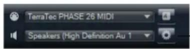
Click here to open the Plug-In Preferences dialog.
- Right-click in the topmost section of the control panel and select "Plug-In Preferences" on the context menu.
The Plug-In Preferences dialog has several tabs on which you can make the following settings:
- On the MIDI Routing tab, you can access the 64 input ports in groups of 16. The groups of input ports are named Rack A, B, C and D. For each rack, you can make the following routing settings:
Option Description
| MIDI Input Ports Use this pop-up menu to specify a MIDI input. | |
| Channel Filter | Use this parameter to decide whether HALion records MIDI events on all MIDI channels, or only on one specific channel. |
| Filter ‘All Notes Off’ Controller | Activate this parameter to avoid unwanted “All Notes Off” messages.Such messages are sent by some keyboards when the last key is released. This causes HALion to stop playback, even when the sustain pedal is still in use. |
- On the Audio Routing tab, use the Audio Output Ports pop-up menus to assign different audio outputs.
HALion supports 64 channels (two Master channels (left and right) and 31 additional left and right stereo channels) and one 5.1 surround channel (with six subchannels). You can assign different audio outputs for each channel. Selecting an audio output on the pop-up menu maps the output to the corresponding channel.
If you press [Shift] and select an audio output, the front and rear channels are set to incrementing audio output ports, for example 1, 2, 3, 4 or 5, 6, 7, 8. If you press [Alt]/[Option]-[Shift] and select an audio output, the audio outputs are assigned in pairs to the front and rear channels, for example 1, 2, 1, 2 or 5, 6, 5, 6.
- On the Metronome tab, you can make the following settings:
Option Description
Mode Here, you can turn the metronome on and off or set it to Count In mode.
Accent Activate this to accentuate the first beat of each bar.
Level Use this fader to adjust the volume of the metronome.
Connections Here, you can select a separate stereo output for the metronome.
- On the General tab, activate "Don't prompt for confirmation when quitting HALion" if you want HALion to close without prompting when quitting the program.
- On the ASIO Driver tab, select your audio hardware driver from the ASIO Driver pop-up menu.
If you plan to use several audio applications simultaneously, you may want to activate the option "Release Driver when Application is in Background".
The input and output latency values for your audio hardware are displayed. "Latency" is the amount of time it takes for your system to respond to any messages that are sent to it. High latency results in a noticeable delay between when you press a key and when you hear the sound. Below the latency values, you can set the sample rate for the connected audio hardware.
When you run HALion, there are several processes fighting for access to processor time in your computer. The parameter "Audio Priority" allows you to determine which processes have priority:
Option Description
Normal In this mode, non-audio processes and audio playback get roughly equal priorities (default setting).
Boost In this mode, audio precedes MIDI in priority. Try this mode if audio playback problems occur when playing back MIDI and audio material.
- Once you have selected the driver, open the Advanced tab to specify which inputs and outputs to use and name these. Click the Control Panel button to open the control panel for the audio hardware and adjust the settings as recommended by the audio hardware manufacturer.
Selecting the MIDI Input and the Audio Output
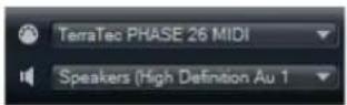
In the top left corner of the control panel, two pop-up menus for selecting the MIDI input and the main audio output of HALion are located.
The MIDI input pop-up menu lists all MIDI devices that are installed on your system.
- Open the MIDI input pop-up menu to select the MIDI device that you want to use.
The MIDI Activity LED in the top left corner of the control panel indicates incoming MIDI messages via the selected MIDI input. The LED lights up on receiving note-on and controller messages. This way, you can check if HALion and your MIDI keyboard are connected to the same MIDI device input.
The Audio output pop-up menu lists all outputs of the selected ASIO device.
- Open the Audio output pop-up menu to select an audio output for the main stereo channel of the plug-in. If you select an audio output, the front and rear channels are set to incrementing audio output ports – for example 1, 2, 3, 4 or 5, 6, 7, 8. Pressing [Alt]/[Option]-[Shift] and selecting an audio output assigns the audio outputs in pairs to the front and rear channels – for example 1, 2, 1, 2 or 5, 6, 5, 6.
Use the Preferences dialog to select the ASIO device and other audio outputs.
The Scratch Pad
Transport controls: Play, Stop, Record, and Loop
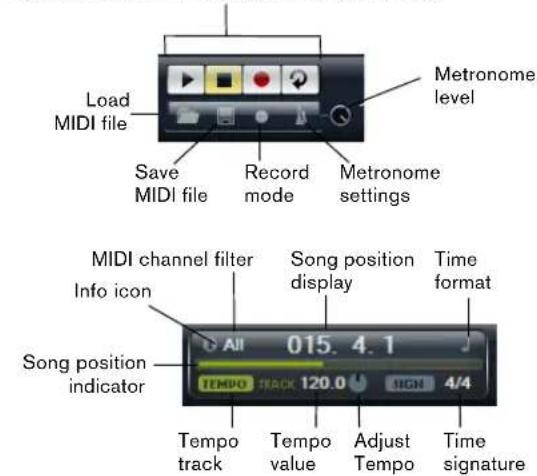
The scratch pad allows you to record and play back MIDI files in Standard MIDI File format (file name extension .mid). You can load existing MIDI files and you can record your own files and save them. The transport section provides buttons for play, stop, record and loop. The display shows the song position, the tempo and the time signature of the MIDI file. In addition, there is a metronome that you can use for recording and practicing.
⇒ The scratch pad can play back multitrack MIDI files sending notes on all 16 MIDI channels. It also sends MIDI program change messages when a MIDI file is loaded.
Using the Transport Controls
- Click the Play button to start playback of the MIDI file. Playback always starts at the song position.
- Click the Stop button to pause the MIDI file at the current position. Click the Stop button twice to reset the song position to the start.
- Click the Record button to start recording.
- Click the Loop button to play the whole MIDI file in a loop.
Loading a MIDI File
To load a standard MIDI file, proceed as follows:
- Click the Load File button below the transport buttons.
- In the file dialog that opens, select the file that you want to use.
- Click Open to load the MIDI file.
Saving a MIDI File
To save the performance you recorded as a MIDI file, proceed as follows:
- Click the Save File button (the disk icon) below the transport buttons.
- In the file dialog that opens, specify a location and a file name.
- Click Save to store the MIDI file.
The Info Icon
To check which MIDI file is currently loaded, point with the mouse at the info icon in the top left corner of the scratch pad. A tooltip appears, showing the name of the MIDI file.
Using the MIDI Channel Filter
When a multitrack MIDI file is loaded, you can decide whether all or only the events of a specific MIDI channel are played back. The control can be found to the right of the info icon in the song position display.
The Song Position Indicator
The song position indicator shows the position of the transport. Above the song position indicator, the position is displayed numerically.
→ After loading a MIDI file, the display shows the full length of the file and the song position indicator is positioned at the end. However, playback starts from the beginning when you click Play.
- To move the transport to a different song position, drag the song position indicator to the new position.
- To change the format, click the time format symbol in the top right corner of the display to switch between the time formats. When Time is selected, a clock is displayed. When Bars is selected, a note is displayed.
Tempo and Time Signature
Below the song position display, the Tempo and Time Signature fields are located. These fields provide HALion with tempo and time signature information. In standalone mode, such information is not available via a host application. In this case, the tempo and time signature settings are used by the scratch pad and the metronome. The following options are available:
Option Description
| Tempo Track/ Fixed | Set this to Track to follow the original tempo of the MIDI file. Set this to Fixed to specify a tempo manually. |
| Tempo Value Determines the tempo of the MIDI file. | |
| Adjust Tempo | When the Tempo Track option is selected, an additional control is displayed that allows you to scale the playback relatively to the original tempo of the MIDI file. |
| Sign (time signature) | Determines the time signature. You can enter the new signature as fractions of beats. |
Recording Your Performance
- Click the record symbol below the Record button to select a record mode.
The following options are available:
Option Description
| Direct The recording starts immediately when you click the record button. | |
| MIDI The recording starts with the first MIDI note. | |
| Count In 1 | The recording starts after a count-in of one bar. |
| Count In 2 | The recording starts after a count-in of two bars. |
- Click the Record button to start the recording.
- When you are done recording, click the Stop button.
- Now you can save your performance as a MIDI file, see "Saving a MIDI File" on page 162.
⇒ To indicate that the recording is running, the song position indicator moves from left to right.
Activating the Metronome
To select the playback mode of the metronome, click the metronome icon. The following options are available on the pop-up menu:
Option Description
Off The metronome is switched off.
Count In The metronome plays only during the count-in of a recording.
On The metronome is always switched on.
The volume control next to the metronome icon allows you to set the volume of the metronome.
Volume
Use the volume control on the right to set the master volume of the outputs of the standalone version of HALion.
This includes the volume of the main outputs, the rear outputs, and the output of the metronome.
Index
A
Activation code 9
Amplifier (effect) 127
Amplifier (section)
Sound (editor) 84
ASIO driver
Selecting 160
Attributes
Editing for Multis 21
Editing in MediaBay 24
Audio
Selecting outputs
(standalone) 161
Audio busses
Adding 36
Audio Routing
About 117
Setup (standalone) 160
Automation 52
AUX busses
Insert effects 53
B
Busses
Adding audio busses 36
Bypassing
Insert effects 53
MIDI modules 54
Note Expression Controller 73
Quick Controls 48
C
CC 121 support 115
CC Mapper 154
CC121, Cl2 & Cl2+ 48
Channel Router (effect) 135
Chorus (effect) 128
Compressor (effect) 131
Content 25
Filtering in MediaBay 23
Loading legacy programs 25
MediaBay 22
Control Panel
About 13
Configuration 13
Cubase
HALion as VST instrument 10
Importing sliced events in HALion 63
D
Distortion (effect) 127
Deactivating globally 40
Insert effects 53
Multi-channel effects 53
Envelope
Snapshots 85
Envelope (section)
Sound (editor) 85
Expander (effect) 132
Exporting
General options 61
Loop sequences 65
Samples 59
External controllers
Al-Knob 48
External sample editors
Specifying 44
F
Filter (section)
Sound (editor) 81
Flanger (effect) 128
FlexPhraser
About 141
Deactivating all instances 40
FXP/FXB files
Importing 26
Loading 25
G
Gate (effect) 133
Global effects 122
Graphic EQ (effect) 126
H
Host application
AU 11
Cubase 10
HSB files
Loading 25
|
Importing
Folders 58
Samples 56
Sliced events from Cubase 63
Sliced loops 63
Third-party programs 62
Insert effects
Adding 36
Installation 9
K
Key commands
Conventions 8
Default key commands 158
Removing Assignments 51
Setting up 51
Key Switch Alternate 151
Key Switch Remote 152
Keyboards
Internal keyboard 41
L
Layer Alternate 150
Layers
About 31
Creating 32
Deleting 32
Editing 67
Muting 35
Saving 32
Soloing 35
Visibility 35
Legacy effects 135
LFO (section)
Sound (editor) 89
Limiter (effect) 132
Loading
Programs into slot 22
Logic Pro 11
Loop layers
Editing 143
Loops
Exporting loop sequences 65
Importing sliced loops 63
REX loops 63
M
Macro pages 17
Main (section)
Sound (editor) 67
Mapping (editor) 98
Mapping Zones 101
Master Section 39
MediaBay
About 22
Attributes 24
Filtering content 23
Rating 23
Results list 23
MegaTrig
About 148
Individual for layers 67
Metronome
Preferences 160
Metronome (standalone)
Activating 163
MIDI
Activity indicator in Slot Rack 20
Routing setup (standalone) 160
Selecting input (standalone) 161
MIDI (editor) 113
MIDI Controller (section)
Options (editor) 44
MIDI Controllers
Assigning 114
Automating 115
MIDI files
Using GM files 26
MIDI modules
Adding 36
Assigning in modulation matrix 54
Bypassing 54
Deleting 54
Inserting 54
MIDI notes
Resetting 41
Selecting zones 41
MIDI Randomizer 153
Mixer 119
Modulation
Destinations 95
Modulation wheel 41
Sources 94
Modulation matrix
Quick controls 48
Modulation Matrix (section)
Assigning MIDI modules 54
Sound (editor) 92
Mono Envelope 145
Mono LFO 147
Multi Delay (effect) 125
Multis
Exporting as VST Sound files 22
Exporting with samples 22
Loading 21
Removing 21
Saving 21
Muting 35
Program Tree 35
Slot Rack 20
N
Navigating
Key commands 158
Program Tree 34
Note Expression 72
0
Options (editor)
Common settings 43
Description 42
Performance (section) 42
Oscillator (section)
Sound (editor) 78
Outputs
Selecting in Cubase 11
P
Performance
Disk streaming 43
Displays 39
Meters 43
RAM Save 40
Performance (section)
Options (editor) 42, 43
Phaser (effect) 129
Pitch (section)
Sound (editor) 78
Pitchbend
Pitchbend wheel 41
Plug-in functions (section) 39
Polyphony
Indicator 39
Programs & layers 70
Setting in Slot Rack 20
Preferences dialog (standalone) 160
Presets
About 51
Editing Attributes 24
Importing in MediaBay 22
VST presets 52
Program slot (section) 39
Program Table
Deleting programs 29
Editing 29
Loading programs 28
Overview 28
Program Tree
About 31
Colors 32
Customizing 36
Selecting elements 33
Sorting 37
Zone numbers 31
Programs 35
About 31
Deleting 32
Editing 67
From Program Table to Slot Rack 29
Importing third-party programs 62
Loading from MediaBay to Slot Rack 22
Loading HALion 3 programs 25
Loading in the Program Table 28
Loading into slot 22
Preloading 29
Saving 32
Q
Quick controls
About 45
Assigning 45
Managing 45
Modulation matrix 48
Quick Controls Assignments (section) 72
R
Recording
To MIDI file (standalone) 162
Registration 10
Release
Programs & layers 71
Repedaling 68
Reverb (effect) 123
REVerence (effect) 123
Root key
Adjusting 102
Importing samples 57
Rotary (effect) 129
Routing 117
S
Sample Editor
About 104
Creating Loops 108
Operations 105
Sample Oscillator (section)
Sound (editor) 80
Samples
Auditioning before replacing 62
Export options 61
Exporting 59
Find missing samples 40
Finding missing samples 58
Importing 56
Prelisten 58
Replacing 61
Setting key range 56
Setting root key 57
Specifying velocity 57
Zone presets 58
Scratch pad (standalone) 161
Screen Sets 15
Signature
Indicator (standalone) 162
Slice Player
Controls 64
Slot Rack
About 19
Loading programs 19, 29
Loading Programs from MediaBay 22
Loading samples & third-party programs 20
Slot controls 20
Soloing 35
Program Tree 35
Slot Rack 20
Sound (editor) 69
Programs & Layers 67
Zones 75
Sphere (control) 42
Splitting
Views & tabs 13
Standalone application
Additional controls 160
Step Modulator (section)
Sound (editor) 91
Stereo Pan (effect) 134
Streaming (section)
Options (editor) 43
Studio EQ (effect) 126
Surround Panner (effect) 134
Sustain
Programs & layers 71
System requirements 9
T
Tabs
Creating 14
Moving 14
Splitting 13
Tempo
Indicator (standalone) 162
Toolbar
Global functions 40
Transport controls (standalone) 161
Tremolo (effect) 129
Trigger (section)
Sound (editor) 67
Trigger mode
For new notes 70
Trigger Pads 144
True Pedaling 154
Tuning Scale 156
U
Undo/Redo
Global functions 41
USB-eLicenser 9
User content 25
V
Variation groups 71
Velocity
Importing samples 57
Velocity Curve 155
Velocity mode
Individual for layers 68
Vibrato (effect) 130
Views
Moving 14
Setting the focus 14
Splitting 13
Voice Control (section)
Sound (editor) 76
Voice groups 70
Voice Management (section) 69
Volume
Control (standalone) 163
VST instrument
HALion in Cubase 10
VST presets 52
VST Sound
Exporting multis 22
W
Wheel controls 41
Window handling 15
Z
Zones
About 31
Creating 32
Deleting 32
Muting 35
Soloing 35
Visibility 35
Zooming
Envelope Section 85
Key commands 158
Mapping Editor 99
Sample Editor 105
Deutsch
Matthias Klag, Michael Ruf
natural_image
Close-up of a transparent plastic USB flash drive (no visible text or symbols)Der USB-eLicenser
Layer in Slots laden
MIDI-Port and Channel
Programme in Slots laden
Enable MIDI Mapping Selection Options
Performance-Bereich
External Wave Editor
Controller Assignment
Receive Program Changes
Octave
Level Velocity Curve
Ind MegaTrig
Filter Ctrls in Release
Ind Sustain
Env Amnt (Envelope Amount)
OSC 1/2/3 Octave (Oct)
Env Amnt (Envelope Amount)
Level Velocity Curve
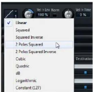
Inv (Invert Envelope)
Bit Red (Bit Reduction)
High EQ Tiefpass-EQ.
KS Off (Key Switches off)
Level Velocity Curve
Available Key Switches
Programme in Slots 190
Layer
Bearbeitung 239
Beschreibung 199
Erzeugen 201
Löschen 201
Soloschalten 204
Speichern 201
Stummschalten 203
Visibility 204
Layer Alternate 332
Legacy-Effekte 315
LFO (Editorbereich)
Sound-Editor 263
Options (Editor) 214
MIDI Randomizer 335
MIDI-Controller
Automation 292
Zuweisen 291
MIDI-Dateien
Options (Editor) 212, 213
Phaser (Effekt) 308
Quick Controls Assignments
(Editorbereich) 244
R
Registerkarten
Erzeugen 181
Teilen 180
Verschieben 181
Registrierung 177
Release
Programme & Layer 243
Repedaling 240
Reverb (Effekt) 301
Options (Editor) 212
431 La section Quick Control Assignments
431 La section Note Expression
natural_image
Close-up of a transparent cylindrical electronic device with a black port and metallic casing (no visible text or symbols)La clé USB-eLicenser
"HALion_Start_Center.exe" (Windows) ou "HALion Start Center.app" (Mac).
Visibility Affiche la colonne Visibility.
Learn Zone Parameter
Find Missing Samples

Section Performance
Key Commands
External Wave Editor
Velocity Note-On to Note-Off
Octave
Level Velocity Curve
Sus, FCtrl, FSw, PB, MW et AT
Filter Ctrls in Release
Ind Sustain
La section Quick Control Assignments
La section Note Expression
Env Amnt (Envelope Amount)
Algorithm Description
Algorithm Description
Env Amnt (Envelope Amount)
Level Velocity Curve
Inv (Invert Envelope)
La barre d'outils

L'onglet Main
Snap to Zero Crossing

Read Root Key and Tuning from File
Show File in Explorer
Commande Description
Slot Output Depending busses
Commande Description
Rate Red (Rate Reduction)
Bit Red (Bit Reduction)
KS Off (Key Switches off)
Level Velocity Curve
Key Follow, Center Key et KeyF Rel (Key Follow Release)
Available Key Switches
MIDI Controller (section)
Modulation Matrix (section)
Assignation de modules MIDI 411
Sound (éditeur) 454
Modules MIDI
Ajout 390
Performance (section) 397
Oscillator (section)
Sound (éditeur) 438
P
Pages Macro 369
Performance
Indicateurs 393
Performance (section)
Quick Controls Assignments
(section) 431
R
Raccourcis clavier
Configuration 407
Conventions 359
Sample Oscillator (section)
Sound (éditeur) 440
Section Master 393
Signature
Slot de programme (section) 393
Slot Rack
À propos 371
Step Modulator (section)
Sound (éditeur) 452
Stereo Pan (effet) 501
Streaming (section)
Voice Control (section)
Sound (éditeur) 435
Voice Management (section) 427
Volume
Commande (version autonome) 533
VST Sound
Exportation de multi-programmes 375
Vues
Déplacement 366
Fractionnement 365
Section Envelope 446
日本語
Matthias Klag, Michael Ruf
改訂管理および品質管理: Cristina Bachmann, Heiko Bischoff, Marion Bröer, Sabine Pfeifer, Heike Schilling, Benjamin Schütte
All rights reserved.
目次
544 インストールと設定
natural_image
Close-up of a black plastic USB flash drive with a circular lens (no visible text or symbols)USB-eLicenser
使用可能なエディターを以下に示します。
Slot Rack
MIDI Port and Channel
Find Missing Samples

natural_image
Close-up of a piano keyboard with green keys and black keys (no visible text or symbols)「PERFORMANCE」セクション
Key Commands
External Wave Editor
Controller Assignment
Receive Program Changes
Velocity Note-On to Note-Off
変数を使用したフォルダーの作成
Octave
音程をオクターブ単位で設定します。
Coarse
音程を半音単位で設定します。
Fine
Filter Ctrls in Release
Ind Sustain
Low Velocity/High Velocity
Env Amnt (Envelope Amount)
OSC 1/2/3 Oct (Octave)
音程をオクターブ単位で設定します。
OSC 1/2/3 Crs (Coarse)
音程を半音単位で設定します。
OSC 1/2/3 Fine
CF Offset (Cutoff Frequency)
Res Offset (Resonance)
Env Amnt (Envelope Amount)
Level Velocity Curve
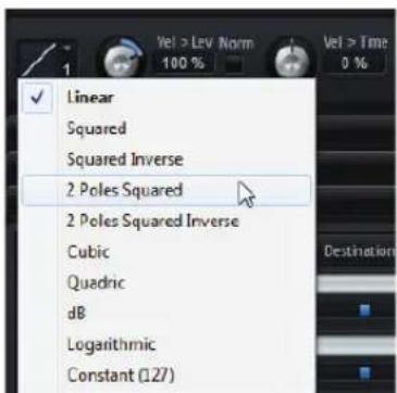
Snap to Zero Crossing

Read Root Key and Tuning from File
Level Velocity Curve
Available Key Switches
- HALION4
- Installation and Setup
- The HALion Control Panel
- Managing Your Sounds
- Loading and Managing Programs
- Using the Program Tree
- Global Functions and Settings
- Common Editing Methods
- Importing and Exporting Samples
- Editing Programs and Layers in the Sound Editor
- Editing Zones in the Sound Editor
- Mapping Zones
- Editing Samples in the Sample Editor
- MIDI Editing and Controllers
- Mixing and Routing
- Effects Reference
- MIDI Modules Reference
- Key Commands Reference
- Using the HALion Standalone Version
- Welcome
- Key Command Conventions
- How You Can Reach Us
- Installation
- The USB-eLicenser
- System Requirements
- Windows
- Macintosh
- Installing HALion
- Register Your Software!
- Setting Up
- Setting Up HALion as a VST Instrument in Cubase
- Accessing HALion via the VST Instruments Window
- Accessing HALion via an Instrument Track
- Selecting Outputs
- Using HALion in an AU Compatible Application
- Introduction
- Configuring the Control Panel
- Select... (Editor)
- "Split |" and "Split --"
- Adjusting the Size of a Split View
- Create Tab
- Renaming Tabs
- Close
- Undock
- Further Setup Options
- Moving Views and Tabs
- Expanding and Resizing Editor Sections
- Setting the Focus
- Working with Multiple Windows
- Creating Additional Windows
- Using Window Presets
- Locking Windows
- Screen Sets
- Screen Set Recommended Resolution
- Description
- Managing Screen Sets
- Overview of the Available Editors
- Slot Rack
- MIDI
- Program Table
- Program Tree
- Sound Editor
- Zone Editor
- MIDI Modules Editor
- Macro
- Mapping Editor
- Sample Editor
- Mixer
- Import
- MediaBay
- Options
- Undo History
- Keyboard
- Quick Controls
- Trigger Pads
- Macro Pages
- The Slot Rack
- Changing the Slot Size
- Size Features
- Showing Empty Slots
- Loading Programs
- Replacing Programs
- Loading Programs in between Slots
- Loading Layers into Slots
- Managing Programs via the Slot Context Menu
- Option Description
- Loading Samples and Third-Party Programs
- Renaming Programs
- Sorting Modes
- Mode Description
- Slot Controls
- Level
- Pan
- Solo
- Mute
- MIDI Port and Channel
- MIDI Activity Indicator
- Polyphony
- Output
- Level Meter
- The Relationship between Slot and Program Table
- Managing Multis
- Loading Multis
- Removing Multis
- Saving Multis
- Creating Subfolders for User-Defined Multis
- Navigating Through the Folder Hierarchy
- Editing Attributes
- Exporting Multis with Samples
- Exporting VST Sound Files
- Managing Files via the MediaBay
- Loading Programs into Slots
- Importing Presets
- Deleting Presets
- Applying Filters
- Category Filter
- Instrument Set Filter
- Using the Results List
- View Filters
- Columns
- Setting Up the Result Columns
- Rating Filter
- Text Search
- Resetting the Result Filter
- Content Filter
- The Results Counter
- Using the Context Menu of the Results List
- Editing Preset Attributes
- Attributes
- Setting the Character Values
- Content Files and Folder Structure
- Loading HALion 3 Programs
- Registering HSB Files
- Registering VST Sound Files
- Loading FXP/FXB Files
- Importing FXP/FXB Files
- Working with General MIDI Files
- The Columns of the Program Table
- Configuring Columns
- Inserting Columns
- Removing Columns
- Reordering Columns
- Changing the Width of a Column
- Loading Programs into the Program Table
- Loading Programs from the Program Table to the Slot Rack
- Creating New Slots
- Replacing Programs in Slots
- Preloading Programs
- Editing the Program Table
- Deleting Programs
- Exchanging the List Positions of Two Programs
- Cut, Copy, and Paste
- Programs and Layers
- Zones
- Busses
- MIDI Modules
- Audio Effects
- The Program Tree Structure
- Number of Selected Zones
- The Color Scheme
- Editing Zones, Programs, and Layers
- Creating Zones
- Creating Layers
- Saving Programs and Layers
- Deleting Programs, Layers, and Zones
- Renaming Entries
- Drag and Drop
- Using Cut, Copy, and Paste
- Paste to New Layer
- Copying and Pasting Zone Settings
- Transfer Settings to Mapping
- Applying Layer Settings to Zones
- Example:
- Making Selections
- Selecting Elements
- Using the Selection Filter
- Expanding and Collapsing the Tree
- Navigating in the Program Tree
- Editing the Focused Entry
- Muting, Soloing, and Hiding
- Muting Layers, Zones, and the Program
- Soloing Layers, Zones, and the Program
- Making all Zones Audible Again
- Using "Solo Follows Selection"
- Using the Visibility Settings
- Using "Auto Visibility"
- Adding MIDI Modules
- Adding Insert Effects
- Changing the Order of MIDI Modules and Insert Effects
- Adding Audio Busses
- Customizing the Program Tree
- Column Description
- Sorting Layers and Zones
- Sorting by Columns
- Sorting the Name Column
- Changing the Sorting Order Manually
- Global Functions and Settings
- The Plug-in Functions Section
- The Plug-in Name
- The Program Slot Section
- Program Icon
- Slot Number
- The Master Section
- Master Volume
- Master Tune
- The Performance Displays
- CPU
- Disk
- # - Polyphony
- MEM (Memory)
- The Toolbar
- Missing Busses
- Find Missing Samples
- Global Insert Effects/AUX Effects/FlexPhrasers
- RAM Save Mode
- MIDI Select
- MIDI Reset
- Undo/Redo
- The Keyboard Editor
- Wheel Controls
- Internal Keyboard
- Display Options
- Color Description
- Triggering Notes
- Sphere Control
- The Options Editor
- Performance Section
- Max Voices
- Max CPU
- Voice Fade Out
- Osc ECO Mode
- Streaming Section
- Balance
- Used Memory and Available Memory
- Performance Meter Section
- Edit Section
- Show Tooltips
- Show Value Tooltips
- Auto Collapse Sections
- Key Commands
- External Wave Editor
- Temp Folder
- Update Sample
- Temp Cleanup
- MIDI Controller Section
- Controller Assignment
- Receive Program Changes
- Receive RPNs 0/1/2
- Smoothing
- Velocity Note-On to Note-Off
- FlexPhraser Hold Reset
- Assigning Quick Controls
- Single Assignment vs. Multi Assignment
- Managing Quick Controls
- Naming Quick Controls
- Duplicating Quick Controls
- Changing the Order of Quick Control Assignments
- Replacing Quick Control Assignments
- Assigning Quick Controls to Another Parameter
- Setting the Scope of Quick Control Assignments
- Setting the Minimum/Maximum Range
- Trimming the Range
- Setting the Default Range
- Adjusting the Curvature
- Setting the Behavior of Quick Control Assignments
- Receiving Quick Controls
- Bypassing Quick Controls
- Assigning Quick Controls in the Modulation Matrix
- AI-Knob Support
- Using Controls in HALion
- Knobs and Sliders
- Multi Selection and Parameter Controls
- On/Off Buttons
- Push Buttons
- Value Fields
- Using Key Commands
- Setting Up Key Commands
- Searching for Functions
- Removing Key Command Assignments
- Working with Presets
- Section and Module Presets
- Loading Presets
- Saving Presets
- VST Presets
- Loading VST Presets
- Inserting VST Presets as Layers
- Replacing Programs and Layers with VST Presets
- Reverting to the Last Saved Program
- Using Automation
- Automation Parameters
- Using Effects
- Using the Insert Effect Slots
- Changing the Output Assignments
- Adjusting the Output Levels
- Muting AUX Busses
- The Master Effect Bus
- Multi-Channel Effects
- Using MIDI Modules
- Inserting a MIDI Module
- Changing the Order of MIDI Modules
- Deleting a MIDI Module
- Bypassing a MIDI Module
- Assigning MIDI Modules in the Modulation Matrix
- Importing and Exporting Samples
- Importing Samples
- Setting the Key Range
- Setting the Root Key
- Specifying the Velocity Range
- Obtaining Information from File and Folder Names
- Using Name Patterns
- Using the Position Setting
- The Tune and Gain Settings
- Listening to Samples before Import
- Sample Zone Presets
- Importing Folders
- Finding Missing Samples
- Entering a Search Path
- Start the Search
- Using Favorite Paths
- Multiple Results
- Search Options
- Exporting Samples
- Creating Folders using Variables
- Renaming Samples
- Example Name Field and Status Messages
- Setting the File Format
- Including Zone Settings
- Setting Up General Export Options
- Replacing Samples
- Replacing a Single Sample
- Replacing Multiple Samples
- Locate the new samples.
- Click OK.
- Auditioning Samples before Replacing Them
- Detecting the Root Key
- The "Change Sample Folder" Option
- Importing Third-Party Sampler Programs
- Using the Import Editor
- Adding a Folder
- Specifying a Destination Folder
- Hide Empty Folders
- Add to MediaBay
- Importing Sliced Loops
- Importing REX Loops
- Importing Sliced Audio Events from Cubase
- Playing back Sliced Loops
- The Slice Player Controls
- Slice Player Presets
- Restart Mode
- Start
- Length
- Quantize
- Amount
- Key Follow
- Center Key
- Random
- Exporting the Loop Sequence
- Using Variations
- Editing Programs and Layers in the Sound Editor
- The Main Section
- Octave
- Coarse
- Fine
- Level Velocity Curve
- Low Key
- High Key
- Low Vel
- High Vel
- Sus, FCtrl, FSw, PB, MW, and AT
- The Trigger Section
- Ind MegaTrig
- Transpose
- Start Key
- Key Switch Mode
- Default Switch
- Filter Ctrls in Release
- Repedaling
- Sustain
- Sostenuto
- Ind Velocity Mode
- Velocity Mode
- Controller
- Velocity Fade
- The Voice Management Section
- Voice Manager
- Voice Mode
- Trigger Mode
- Voice Groups
- Assigning Zones to Voice Groups
- Editing Voice Groups
- Exclusive Groups
- The Poly Tab
- Mono
- Retrigger
- Key Poly
- Low Amp
- Min Low Notes
- The Sus/Rel Tab
- Ind Sustain
- Sustain Mode
- Play Release
- The Variation Groups Section
- Assigning Zones to Variation Groups
- The Quick Control Assignments Section
- Name
- The Note Expression Section
- Naming Note Expression Controllers
- Bypassing the Note Expression Controller
- Changing the Modulation Depth
- Editing Zones in the Sound Editor
- Global Zone Settings
- Focused Zone
- Low Key/High Key
- Low Vel/High Vel
- Root Key
- Zone Type
- Editing Selected Zones or All Zones
- Absolute and Relative Editing
- HALion 3 compatibility
- The Voice Control Section
- The Trigger Tab
- Voice Group
- Variation Group
- Priority
- Fade Out
- Key On Delay
- Release Mode and Amount
- The Unison/Glide Tab
- Unison
- Glide
- Glide Groups
- Use Start Range
- The Pitch Section
- Pitchbend
- Env Amnt (Envelope Amount)
- The Oscillator Section
- OSC 1/2/3 Waveform
- OSC 1/2/3 Octave (Oct)
- OSC 1/2/3 Coarse (Crs)
- OSC 1/2/3 Fine
- OSC 1/2/3 Level
- Sub Oscillator (SUB)
- Ring Modulation (RING)
- Noise
- The Sample Oscillator Section
- The Main Tab
- Playback Mode
- Quality
- Preload
- Sample Start Range
- Fixed Pitch
- The Loop Tab
- The Filter Section
- Filter Type
- Filter Mode
- Filter Shape
- Cutoff
- X/Y Control
- Resonance
- Distortion
- CF Offset
- Res Offset
- Velocity
- Norm
- Fatness
- Bypass
- The Amplifier Section
- Headroom
- Mode
- Alternate
- Reset
- The AUX Tab
- AUX 1-4
- The Envelope Section
- Zooming and Navigating in the Graphical Envelope Editor
- Envelope Zoom Snapshots
- Saving and Loading Envelope Zoom Snapshots
- Editing the Envelope
- Selecting Nodes
- Adjusting the Time Parameter
- Adjusting the Level Parameter
- Adjusting the Curve Parameter
- Adding and Removing Nodes
- Adding Nodes Using the Fill Function
- Fixed
- Snap
- Using Sync
- Selecting an Envelope Mode
- Setting Up the Loop
- Level Velocity (Vel>Lev)
- Time Velocity (Vel>Time)
- Segments
- Key Follow and KeyF Rel
- The LFO Section
- LFO Waveform and Shape
- Sync Mode
- Retrigger Mode
- Frequency
- Phase
- Rnd (Random)
- Delay
- Fade In
- Hold
- Inv (Invert Envelope)
- Envelope Mode
- Graphical Envelope Editing
- The Step Modulator Section
- Editing Steps
- Steps
- Note
- Triplets
- Slope
- Step
- Producing Modulations in Steps of Semitones
- The Modulation Matrix Section
- Using the Modulation Rows
- Managing Modulation Rows
- Unipolar vs. Bipolar Sources
- Using the Curve and Range Editor
- Setting Up a Modulation
- Modulation Sources
- Modulation Destinations
- Sample & Hold
- Using Global MIDI Controllers
- The Mapping Editor
- The Zone Range Section
- The Mapping Editor Keyboard
- Testing the Sample Mapping
- The Velocity Scale
- Setting the Focus in a Multi-Selection
- Zooming and Scrolling
- Automatic Scrolling to a Tree Selection
- Zoom Snapshots
- Selecting Zones
- Moving Zones
- Move Lock
- Setting Key and Velocity Range
- Graphically
- Numerically
- Muting and Soloing Zones
- Showing and Hiding Zones
- Auto Visibility
- Fading and Crossfading Zones
- Curve Shape
- Auto Crossfades
- Symmetric Crossfades
- Triggering Zones
- Importing Samples Using Drag and Drop
- Mapping Zones
- Filling Gaps between Zones
- Selecting Zones with the Mapping Editor Keyboard
- Editing Samples in the Sample Editor
- Overview
- The Info Line
- The Overview Line
- The Ruler
- The Waveform Display and the Level Scale
- The Parameter Section
- General Operations
- Zooming
- View Range
- Auditioning Samples
- Using the Edit Loop Function
- Using the Play Tool
- Scrubbing
- Selecting an Output for the Sample Editor
- Markers
- Marker Function
- Selections
- Defining Sample Start and End from a Selection
- Creating New Zones from Selections
- Snapping
- Snap to Markers
- Snap to Zero Crossing
- Auto-Scroll
- Read Root Key and Tuning from File
- Show File in Explorer
- Editing Samples in an External Editor
- Channel View Options
- Creating Loops
- Setting Up a Loop
- Selecting a Loop Type
- Moving Start and End Markers
- Detecting Loop Start and End Automatically
- Using Edit Mode
- Setting Up Loop Crossfades
- Adjusting the Crossfade Curve
- Adjusting the Tuning
- Using Loopsets A and B
- Additional Loop Options
- Creating Loops from Selections
- Reading Loop Information from Sample Files
- Using the Loop Submenu
- The MIDI Editor
- Parameters
- Channel
- Poly (Polyphony)
- Key Range (Low Key, High Key)
- Velocity Range (Low Vel, High Vel)
- Controller Filter
- Using MIDI Controllers
- Assigning MIDI Controllers
- Setting the Parameter Range
- Assigning MIDI Controllers to AUX FX
- Saving a MIDI Controller Mapping as Default
- Restoring the Factory MIDI Controller Assignment
- Automation and Factory MIDI Controller Assignments
- CC 121 Support
- The Audio Bus Architecture
- The Default Audio Signal Flow
- Audio Busses
- AUX Busses
- Layers
- Programs
- Slots
- Editing Audio Busses
- Creating Audio Busses
- Changing the Output Assignment of an Audio Bus
- Changing the Output Assignment of an AUX Bus
- Changing the Output Assignments of Zones
- Automatic Bus Width Adaptation
- Automatic Output Connection
- Output Configurations in Different Hosts
- Apple Logic 9
- Ableton
- Sonar 9
- The HALion Mixer
- The Toolbar Options
- Displaying Different Mixer Channels
- Expanding and Collapsing all Mixer Channels
- Showing Empty Slot Channels
- Hiding Deactivated Output Channels
- Channel Color
- Meter
- Peak Level
- Channel Label
- Insert Effects
- Pre-Fader Send Effects
- Changing the Order of Effects
- Effects Reference
- Reverb and Delay Effects
- Impulse Response
- Reverse
- PreDelay
- Time
- Size
- Equalizer
- ER Tail Split
- ER/Tail Mix
- Early Reflections
- Low Cut
- High Cut
- Room Size
- Main Time
- High Time
- High Freq
- Low Time
- Low Freq
- Shape
- Density
- Width
- Mix
- Sync
- Delay L/R
- Feedback
- Feedback L/R
- Filter Low
- Filter High
- EQ Effects
- Range
- Invert
- Flatten
- Distortion Effects
- Amplifier
- Amp Model
- Speaker Model
- Drive
- Bass
- Middle
- Treble
- Presence
- Low Damp
- High Damp
- Channel Mode
- In Gain
- Rate Red (Rate Reduction)
- Tube Drive
- Hard Clip
- Bit Red (Bit Reduction)
- Out Gain
- Modulation Effects
- Chorus
- Rate
- Depth
- Flanger
- Cross FB
- Tone
- Phaser
- Shift
- Tremolo
- Rotary
- Rotation
- Distance
- Cabinet
- Slow
- Fast
- Accel
- Horn Mic Angle
- Drum Mic Angle
- Gain
- Vibrato
- Type
- Custom Mode
- Vibr/Chor
- Dynamics Effects
- Threshold
- Ratio
- Soft Knee
- Make-Up
- Auto
- Attack
- Release
- Auto Release
- Peak - RMS
- Limiter
- Input
- Expander
- Filter
- Monitor
- Center
- Q-Factor
- Panner and Routing Effects
- Input Swap
- Restricting Movement
- Modifier key(s) Description
- Left / Right
- Front / Rear
- LFE
- Rotate
- Orbit Center
- Radius
- Center Distribution
- Channel Router
- Downmix
- HALion 3 Legacy Effects
- Hall Reverb
- Parameter Description
- Non-Linear Reverb
- Stereo Delay
- Long Delay
- Tape Delay
- Ensemble
- Pan / Tremolo
- Stereo Width
- Rotary Speaker
- Wah Pedal
- TalkBox
- Shelf EQ
- Parametric EQ
- Enhancer
- Compressor
- Multiband
- Gate
- Overdrive
- Bit Reduction
- Amp Simulator
- Modulate L/R
- The FlexPhraser
- FlexPhraser presets
- Loading Phrases for the FlexPhraser
- Phrase Playback Types
- KS Off (Key Switches off)
- Loop
- Key Mode
- Vel Mode
- Tempo
- Tempo Scale
- Swing
- Gate Scale
- Vel Scale
- Octaves
- Play Range
- Working with FlexPhraser Variations
- Creating Variations
- Switching Variations with the Trigger Pads
- The Trigger Pads
- Assigning Trigger Notes to Pads
- Using Default Trigger Note Settings
- Naming a Pad
- Triggering Chords or Single Notes
- Switching between FlexPhraser Variations
- Bypassing the Trigger Pads
- Using Pad Presets
- Mono Envelope
- Release Mode
- Level Velocity
- Time Velocity
- Key Follow, Center Key, and KeyF Rel (Key Follow Release)
- Mono LFO
- LFO Presets
- LFO Parameters
- LFO Waveform Types
- LFO Bypass
- MegaTrig
- Setting up Conditions
- Setting up the Expression Manually
- Selecting a Condition
- Trigger Options
- Note-Off Velocity
- Layer Alternate
- Alternation
- Expression Pool
- Alternation List
- Using Key Switches
- Alternation Mode
- Per Key
- Enable
- Previous/Next
- Grace Time
- Key Switch Alternate
- Available Key Switches
- Adding New Alternations
- Naming Alternations
- Alternation Mode, Per Key, Reset, and Enable
- Key Switch Remote
- Key Switch
- Remapped
- MIDI Controller
- Refreshing the Expression List
- MIDI Randomizer
- True Pedaling
- CC Mapper
- Source
- Min
- Max
- Velocity Curve
- Curve display
- Minimum and Maximum
- Controller Mode
- Off
- Switch
- Continuous
- Side-Chain Controller
- Tuning Scale
- Editing Tuning Scales
- Editing Scales per Octave
- Editing Scales per Note
- Absolute Mode
- Importing Scala Files
- Adjusting the Amount
- The Default Key Commands
- Edit
- Using the HALion Standalone Version
- Making Preferences Settings
- Selecting the MIDI Input and the Audio Output
- The Scratch Pad
- Using the Transport Controls
- Loading a MIDI File
- Saving a MIDI File
- The Info Icon
- Using the MIDI Channel Filter
- The Song Position Indicator
- Tempo and Time Signature
- Recording Your Performance
- Activating the Metronome
- Volume
- A
- B
- C
- D
- F
- G
- H
- |
- K
- L
- M
- N
- 0
- P
- Q
- R
- S
- T
- U
- V
- W
- Z
- Layer in Slots laden
- MIDI-Port and Channel
- Programme in Slots laden
- Enable MIDI Mapping Selection Options
- Performance-Bereich
- Section Performance
- Sus, FCtrl, FSw, PB, MW et AT
- La section Quick Control Assignments
- La section Note Expression
- La barre d'outils
- L'onglet Main
- Commande Description
- Key Follow, Center Key et KeyF Rel (Key Follow Release)
- Alternation Key Switch
- 「PERFORMANCE」セクション
- 変数を使用したフォルダーの作成
- Low Velocity/High Velocity
- OSC 1/2/3 Oct (Octave)
- OSC 1/2/3 Crs (Coarse)
- CF Offset (Cutoff Frequency)
- Res Offset (Resonance)
Brand : STEINBERG
Model : HALion 4
Category : Audio software