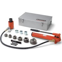
HKO-186 - Hydraulic tool RIDGID - Free user manual and instructions
Find the device manual for free HKO-186 RIDGID in PDF.


| Product Type | Hydraulic Knockout Set |
| Brand | RIDGID |
| Model | HKO-186 |
| Pump | Manual type H-18 |
| Maximum Pressure | 10,000 PSI (689 bar) |
| Punching Capacity | 1/2 in to 2 in (12.7 mm to 50.8 mm) |
| Max. Sheet Thickness (Mild Steel) | 3.4 mm (10 gauge) |
| Max. Sheet Thickness (Stainless Steel) | 1.6 mm (16 gauge) |
| Piston Stroke | 1 in (25.4 mm) |
| Piston Capacity | 11.2 tons |
| Piston Weight | 5.3 lb (2.4 kg) |
| Pump Weight (without oil) | 7.5 lb (3.4 kg) |
| Reservoir Capacity | 18.6 in³ (305 cm³) |
| Usable Oil Volume | 16 in³ (262 cm³) |
| Hose Length | 3 ft (0.91 m) |
| Power Source | Manual (hydraulic pump) |
| Main Functions | Punching holes in sheet metal |
| Maintenance | Drain every 300 hrs, bleed air, clean fittings |
| Safety | Safety glasses, hose inspection, do not exceed pressure |
| Spare Parts | Use genuine RIDGID parts |
| Warranty | RIDGID Lifetime Warranty |
Frequently Asked Questions - HKO-186 RIDGID
User questions about HKO-186 RIDGID
0 question about this device. Answer the ones you know or ask your own.
Ask a new question about this device
Download the instructions for your Hydraulic tool in PDF format for free! Find your manual HKO-186 - RIDGID and take your electronic device back in hand. On this page are published all the documents necessary for the use of your device. HKO-186 by RIDGID.
USER MANUAL HKO-186 RIDGID
HKO-186 HKO-1810 FKO-186 FKO-1810
OPERATOR'S MANUAL
Read this Operator's Manual carefully before using this tool. Failure to understand and follow the contents of this manual may result in serious personal injury.
Hydraulic Knockout Sets
natural_image
Product photo of a red hydraulic pressure pump with attached mechanical components and a gray metal toolbox labeled 'RIDGID' (no text or symbols on main objects)Table of Contents
General Safety Information
Work Area 2
Personal Safety 2
Tool Use and Care....2
Service....2
Specific Safety Information
Hydraulic Hose 2
Hydraulic Pump 3
Hydraulic Cylinder 3
Description, Specifications and Standard Equipment
Description....3
Specifications....3
Standard Equipment 4
Tool Assembly And Inspection....4
Operating Instructions
Set-Up To Punch 12 " Holes .....5
Set-Up To Punch ^3/4 Through 4" Holes....5
Using Model H-18 Hand Pump 6
Using Model HF-18 Foot Pump 6
Maintenance Instructions
Lubrication 6
Periodic Cleaning....6
Bleeding Air From System....7
Inspecting The Fluid Level....7
Draining And Flushing The Reservoir 7
Refilling The Reservoir 7
Tool Storage 7
Service And Repair 8
Troubleshooting....9
Lifetime Warranty ....Back Cover
HK0-186/1810
FK0-186/1810
Hydraulic Knockout Sets
natural_image
Product photo of a RIDGID hydraulic tool kit with attached cylindrical and mechanical components (no visible text or symbols)| HKO-186/1810, FKO-186/1810 Hydraulic Knockout Sets | |
| Record Serial Number below and retain product serial number which is located on nameplate. | |
| Serial No. | |
General Safety Information
WARNING! Read and understand all instructions. Failure to follow all instructions listed below may result in serious personal injury.
SAVE THESE INSTRUCTIONS!
Work Area
- Keep your work area clean and well lit. Cluttered benches and dark areas invite accidents.
- Keep by-standers, children, and visitors away while operating a tool. Distractions can cause you to lose control.
Personal Safety
- Stay alert, watch what you are doing and use common sense when operating a tool. Do not use tool while tired or under the influence of drugs, alcohol, or medications. A moment of inattention while operating tools may result in serious personal injury.
- Dress properly. Do not wear loose clothing or jewelry. Contain long hair. Keep your hair, clothing, and gloves away from moving parts. Loose clothes, jewelry, or long hair can be caught in moving parts.
- Do not overreach. Keep proper footing and balance at all times. Proper footing and balance enables better control of the tool in unexpected situations.
- Use safety equipment. Always wear eye protection. Dust mask, non-skid safety shoes, hard hat, or hearing protection must be used for appropriate conditions.
Tool Use and Care
- Store idle tools out of the reach of children and other untrained persons. Tools are dangerous in the hands of untrained users.
- Maintain tools with care. Keep cutting tools sharp and clean. Properly maintained tools with sharp cutting edges are less likely to bind and are easier to control.
- Check for misalignment or binding of moving parts, breakage of parts, and any other condition that may affect the tool's operation. If damaged, have the tool serviced before using. Many accidents are caused by poorly maintained tools.
- Use only accessories that are recommended for your tool. Accessories that may be suitable for one tool may become hazardous when used on another tool.
- Keep handles dry and clean; free from oil and grease. Allows for better control of the tool.
Service
- Tool service must be performed only by qualified repair personnel. Service or maintenance performed by unqualified repair personnel could result in injury.
- When servicing a tool, use only identical replacement parts. Follow instructions in the Maintenance Section of this manual. Use of unauthorized parts or failure to follow maintenance instructions may create a risk of injury.
Specific Safety Information
WARNING
Read this operator's manual carefully before using the RIDGID Hydraulic Knockouts. Failure to understand and follow the contents of this manual may result in serious personal injury.
Call the Ridge Tool Company, Technical Service Department at (800) 519-3456 if you have any questions.
Hydraulic Knockout Safety
- The hydraulic components in this set are designed only for punching holes in metal. The ram, pump, hose or coupling from this system should not be used for other applications such as jacking, pulling, pushing or raising loads. Other uses or modifying the hydraulic components for other applications may increase the risk of injury.
- The knockouts are designed to punch holes in low carbon, mild steel up to 10 gauge maximum thickness or stainless steel up to 16 gauge. Using this tool for any other purpose can result in serious personal injury and damage to the tool.
Hydraulic Hose
- Should a hydraulic hose burst or rupture, immediately stop operating the pump before attempting to remedy the situation. Never attempt to grasp a leaking hose under pressure with your hands. A leaking hose should be replaced. The force of the escaping hydraulic fluid could cause serious injury.
- Avoid any conditions which could damage the hose and impair the pump's performance. Never allow the hose to kink, twist, curl or bend so tightly that the oil flow within the hose is blocked or restricted. This damages the hose and could possibly result in serious injury to persons working in the immediate vicinity.
- Do not over-tighten the connections. Connections need only be tightened securely and leak-free. Over-torque may cause premature thread failure and may cause high pressure fittings to split at pressures lower than their rated capacities.
- Do not subject the hose to any potential hazard such as fire, extreme heat or cold, heavy impact or sharp surfaces. Do not use the hose to lift or move the equipment connected to it.. Might rupture or weaken the hose.
- Periodically inspect the hose for signs of wear. Never use a defective hose with any pressurized equipment. Escaping hydraulic fluid could cause serious injury.
- Never paint the couplers, fittings or hose. Make sure that the hose material and coupler seals are compatible with the hydraulic fluid used. Avoid contact with creosote-saturated materials. May result in hose damage and leaking of hydraulic fluid.
Hydraulic Pump
- Never exceed the rated capacity of the unit. Never tamper with the internal high pressure relief valve. May result in pump failure.
- Always retract the system before replenishing the oil level. Never over-fill the pump reservoir with oil. Could damage the pump.
Hydraulic Cylinder
- Keep the cylinder clean at all times. Keep the piston fully retracted when the cylinder is not in use. Prevents damaging the cylinder.
- Make certain that the hydraulic fluid added to the system is compatible with the seals and the existing fluid. Never use brake fluid. May result in leaking of the hydraulic fluid.
Description, Specifications and Standard Equipment
Description
RIDGID Hydraulic Knockout Sets are designed for punching holes of 12 " through 4" (conduit size) diameter in mild steel of up to 10 gauge (.134" / 3.40mm) maximum thickness.
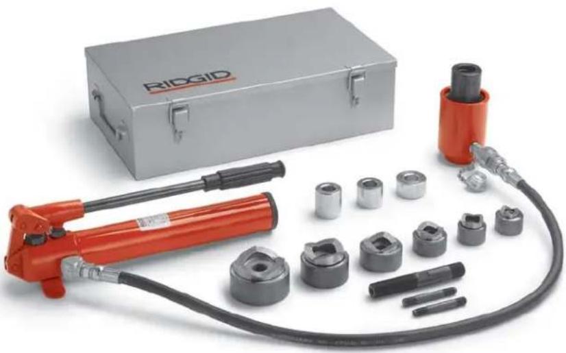
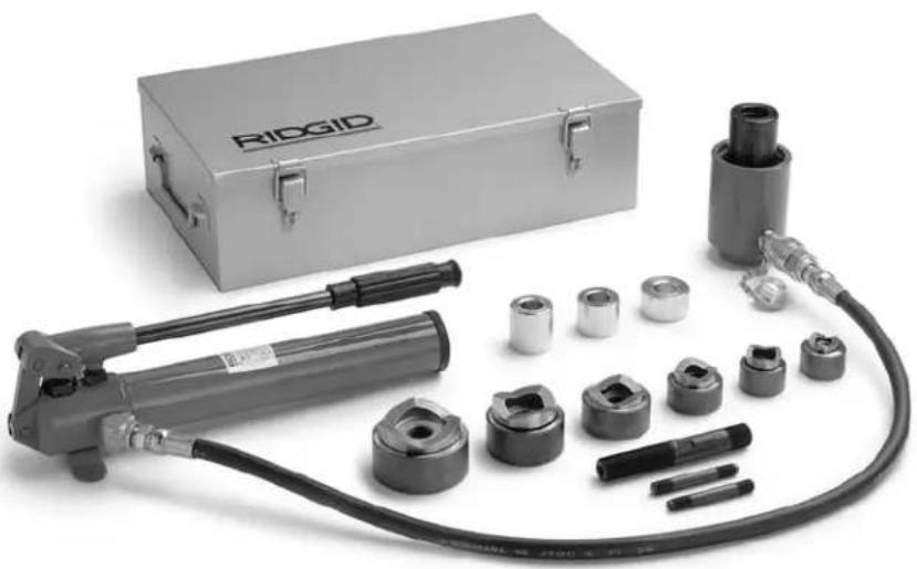
The RIDGID Model HKO-186 Knockout Set includes the H-18 Hand Pump, 8R111S Hydraulic Cylinder, 3 ft. hose, 12'' -2" Punch/Die Sets and various accessories. The Model FKO-186 Knockout Set is the same basic set
except that the HF-18 Foot Pump is included in place of the hand pump and a 10 ft. hose is provided.
The single-stage hand pump will develop up to 10,000 PSI pressure with a maximum handle effort of 80 lbs. The two-stage foot pump will develop 10,000 PSI of pressure with maximum lever effort of 143 lbs. Both pumps incorporate an internal relief valve set at 10,000 PSI. The ram will develop up to 100 tons of force at 10,000 PSI and has a 1" stroke.
Specifications
Ram:
Capacity......11.2 Tons
Stroke.....1 Inch
Oil Volume......2.45 cu. in.
Weight 5.3 lbs.
Punch Diameter
(Conduit Size).... ^1/2 " through 4"
Maximum Plate
Thickness.....10 Gauge (.134" / 3.4mm)
Pump: H-18 HF-18
Stage .... Single.... Two
Volume Per Stroke:
Low Pressure 670 cu. in.
High Pressure ....0.061 cu. in....0.061 cu. in.
Valve ....2-Way ....2-Way
Maximum Pressure .....10,000 PSI.....10,000 PSI
Reservoir Capacity.....18.6 cu. in. .....18.6 cu. in
Useable Volume.....16 cu. in. .....16 cu. in
Maximum Lever Effort ...80 lbs.....143 lbs.
Oil Port....3/8" NPTF....3/8" NPTF
Weight (w/o Oil) .....7.5 lbs. .....11 lbs.
Relief Valve.....Yes .....Yes
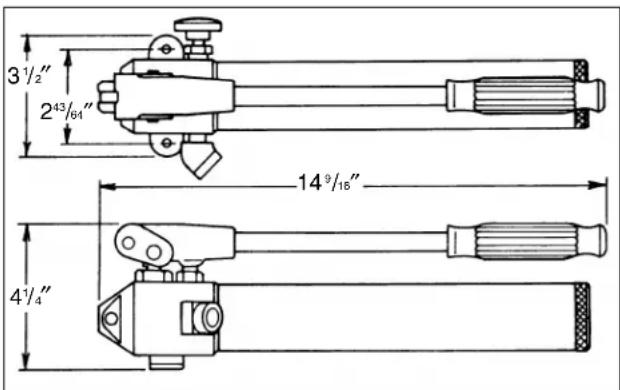
Hydraulic Hand Pump
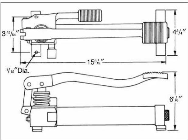
Hydraulic Foot Pump
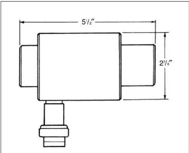
Hydraulic Ram
Standard Equipment
Model No. Description
HKO-186 12 - 2" Hydraulic Kit w/Hand Pump Includes:
• H-18 Hand Pump
- Hydraulic Cylinder
- 3 ft. Hose
- 1/2 - 2'' Pump/Die Sets
HKO-1810 12 - 4" Hydraulic Kit w/Hand Pump Includes:
• H-18 Hand Pump
• Hydraulic Cylinder
- 3 ft. Hose
- 1/2 - 4" Pump/Die Sets
FKO-186 12 - 2" Hydraulic Kit w/Foot Pump Includes:
- HF-18 Foot Pump
- Hydraulic Cylinder
- 10 ft. Hose
- ^1/_2 - 2" Pump/Die Sets
FKO-1810 12 - 4" Hydraulic Kit w/Foot Pump Includes:
- FF-18 Foot Pump
• Hydraulic Cylinder - 10 ft. Hose
- ^1/_2 - 4" Pump/Die Sets
Tool Assembly and Inspection
WARNING
To prevent serious injury, proper assembly and inspection of the Hydraulic Knockout Sets is required. Inspection procedures should be performed before each use
Assembly
- Clean all the areas around the oil port of the pump and ram. Inspect all threads for signs of wear or damage and replace as needed. Clean all hose ends, couplers and union ends. Remove the thread protector (if so equipped) from the hydraulic oil outlet.
- Connect the hose half coupler at the end of the hose to the ram half coupler on the cylinder. Turn the collar completely on hand-tight (Figure 1).
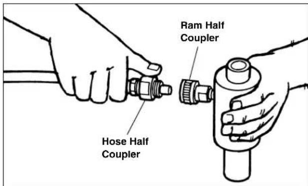
Figure 1 – Hydraulic Connections
NOTE! Although a high-grade, non-hardening thread sealant is preferred, PTFE tape may be used to seal hydraulic connections provided only one layer of tape is used. To prevent the tape from being "pinched" and broken off inside the system, apply tape carefully avoiding the first one or two threads. Any loose pieces of tape will travel through the system and obstruct the flow of oil or cause jamming of precision parts.
CAUTION Do not over-tighten the connections. Connections need only be tightened securely and leak-free. Over-torque may cause premature thread failure.
Inspection
- Inspect pump and ram for signs of wear or damage which may affect its safe and normal operation. If any of these conditions exist, do no use the tool until it has been repaired.
- Clean any oil, grease or dirt from the handles. This reduces risk of injury due to a tool slipping from your grip.
- Inspect the hose for signs of wear. Never use a defective hose with any pressurized equipment. Hose should be replaced before using this tool.
Operating Instructions
WARNING
The Knockouts are designed to punch holes in low carbon, mild steel up to 10 gauge maximum thickness or stainless steel up to 16 gauge. Never use pump, hose or ram if damaged, altered or in poor repair.
Always wear eye protection to protect your eyes against dirt and other foreign objects. Never exceed rated capacity of the unit or tamper with the internal high pressure relief valve.
Set-Up To Punch ^1/_2 Holes
- Mark the center of the hole to be punched and drill a 716 " pilot hole. If accuracy is critical in locating a hole, scribe center gage lines at 90 degrees to each other through the center mark. Gage marks on the outside diameter of the die can then be aligned with the scribed lines for accurate hole positioning.
-
Screw the short threaded end of the 34 " draw bolt into the threaded hole of the ram. The bolt should be screwed in fully, but only hand-tight.
-
Screw the 38 " adapter screw into the 34 " bolt fully but only hand-tight.
- Place three spacers over the 34 " draw bolt starting with the shortest and continuing with medium and long spacers (Figure 2).
NOTE! Be sure ram is fully retracted before assembling punch and die set on ram. - Place the 12 " die over the 38 " draw bolt, pass the end of the bolt through the previously drilled pilot hole and thread the punch on the end of the bolt so that the points just touch the material (Figure 3). Operate the pump as described below.
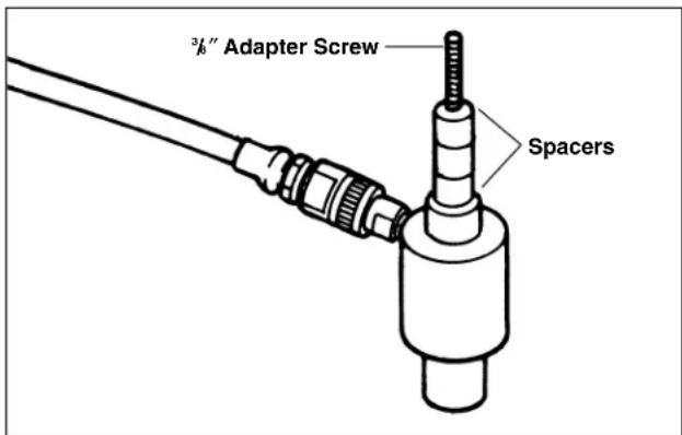
Figure 2 – Set-Up For ^1/2 " Holes
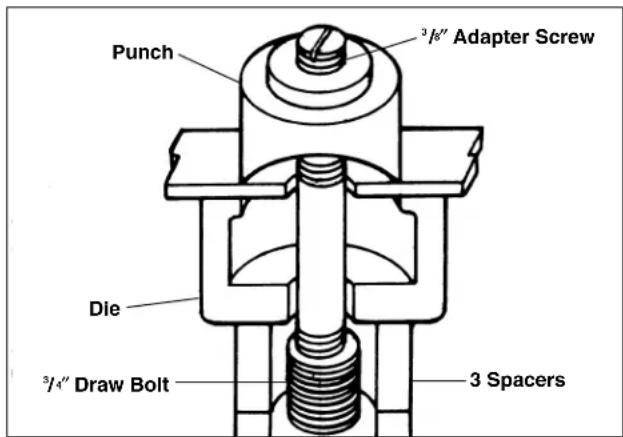
Figure 3 – Punching ^1/2 " Holes
Set-Up To Punch ^3/_4 " Through 4" Holes
-
Mark the center of the hole to be punched and drill a ^13/16'' or ^7/8'' pilot hole. If accuracy is critical in locating a hole, scribe center gage lines at 90 degrees to each other through the center mark. Gage marks on the outside diameter of the die can then be aligned with the scribed lines for accurate hole positioning.
-
Screw the short threaded end of the 34 " draw bolt into the threaded hole of the ram. The bolt should be screwed in fully, but only hand-tight.
NOTE! Be sure ram is fully retracted before assembling punch and die set on ram.
-
When using 34 " or 1" die, place the shortest spacer over the draw bolt and then add the desired die. When using 114 " through 4" die, no spacer should be used since the die is designed to rest directly on the ram body.
-
Pass the end of the draw bolt and the end of the bolt through the previously drilled pilot hole and thread the punch onto the end of the bolt so that the punch points just touch the material (Figure 4). Operate the pump as described below.
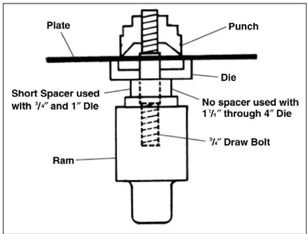
Figure 4 – Punching ^3/_4 " Through 4" Holes
A. Using Model H-18 Hand Pump
- Close the release valve of the pump by turning fully clockwise.
- Operate the pump handle until the punch has cut completely through the material
CAUTION Sudden application of hydraulic pressure may cause punch/die misalignment and damage the points. Operate the pump at a moderate speed.
⚠ WARNING As the hole is punched, the ram will punch and die may fall out of the hole. To prevent injury, support the ram as the hole is completed.
-
Open the release valve of the pump to allow punch to be returned from die. Be sure ram retracts completely.
-
Unscrew the punch from the draw bolt and remove the slug from the die.
B. Using Model HF-18 Foot Pump
- Operate the foot pedal until the punch has cut completely through the material.
CAUTION Sudden application of hydraulic pressure may cause punch/die misalignment and damage the points. Operate the pump at a moderate speed.
⚠ WARNING As the hole is punched, the ram will punch and die may fall out of the hole. To prevent injury, support the ram as the hole is completed.
- Depress the release pedal to allow punch to be returned from die. Be sure ram retracts completely.
- Unscrew the punch from the draw bolt and remove the slug from the die.
NOTE! When the points of the punch become worn, it should be replaced immediately. Otherwise, cuts will not be uniform and damage to the draw bolt may result. Stop pumping as soon as the hole has been complete to avoid damaging the punch set. Never force points of punch into contact with the die.
Maintenance Instructions
WARNING
Any repairs or service which requires dismantling the pump or ram must be performed in a dirt-free environment. All maintenance should be performed by a qualified technician.
Lubrication
Apply lubrication periodically to all pivot and rubbing points. Use a good grade of No. 10 motor oil. Do not use dry lubricants.
Periodic Cleaning
A preventative maintenance program should be established to keep the hydraulic components as free from dirt as possible. Make certain that the hydraulic oil outlet and all unused couplers are sealed with thread protectors whenever the hydraulic system is dismantled. Be sure all hose connections are free of contamination. Use only an approved, clean hydraulic oil and change as recommended, every 300 hours.
Bleeding Air From The System
During the initial moments of activation or after prolonged use, a significant amount of air may accumulate within the hydraulic system. This entrapped air may cause the cylinder to respond slowly or behave in an unstable manner. To remove the air, operate the system through several cycles (extending and retracing the ram) free of any load. Make certain the ram is at a lower level than the pump with the coupling pointing upwards to allow air to be released into the pump reservoir. Once all the air has been bled from the system, inspect the oil level and fill the reservoir to the proper level if necessary.
Inspecting The Hydraulic Fluid Level
IMPORTANT: Always retract the ram completely before attempting this procedure.
Check the oil level in the reservoir after approximately every ten hours of use. Place the pump in a vertical position with the reservoir cap up. While holding the reservoir, unscrew the cap to determine if the oil level is between the fill marks on the inside of the reservoir (Figure 5). If oil is low, add enough to bring level between lines. If oil is dirty, following instructions below in the section entitled, "Draining and Flushing the Reservoir".
NOTE! On Foot Pump Model HF-18, a dipstick is attached to the filler cap. To check oil level, hold pump in a vertical position with filler cap up, remove dipstick and wipe clean. Insert dipstick and remove to view oil level. Proper oil level is indicated by upper mark on dipstick (Figure 5).
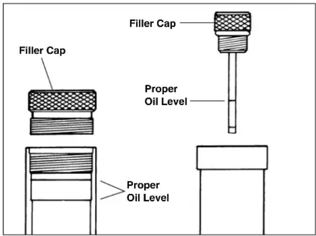
Figure 5 – Checking Oil Levels
Before replacing the reservoir cap, visually inspect the o-ring which seals the cap/reservoir assembly. Replace this o-ring if it is damaged. Reinstall reservoir cap to reservoir and tighten securely. Check for leaks.
CAUTION Do not overfill the pump reservoir as this will adversely affect pump performance.
Draining and Flushing The Reservoir
Wipe the pump exterior completely clean before attempting this procedure.
It is important that after 300 hours of operation, the pump be drained of oil completely and flushed out with a suitable, compatible flushing solution before refilling it with clean hydraulic fluid. To do this, unscrew the reservoir cap from the reservoir and properly discard the used hydraulic fluid. Flush the reservoir vigorously to ensure that no contaminants remain. Clean or replace the pump intake screen at this time. Refill the reservoir in the manner described below in the section entitled "Refilling The Reservoir".
NOTE! Drain and clean the other hydraulic system components (hoses, cylinders, etc.) before reconnecting them to the pump. This will prevent contaminated oil from reentering the pump.
Refilling The Reservoir
NOTE! Always retract the ram completely before attempting this procedure.
Place and support the pump in a vertical position with the filler cap facing upward. Unscrew and remove the reservoir cap from the reservoir. If additional oil must be added to the reservoir, use only an approved high grade hydraulic oil. Clean the entire area around the open rim of the reservoir cap, visually inspect the o-ring which seals the cap/reservoir assembly. Replace this o-ring if it is damaged. Reinstall cap to reservoir and tighten securely. Check for leaks.
CAUTION Do not overfill the pump reservoir as this will hinder pump performance.
Tool Storage
WARNING
Tools must be kept indoors or well covered in rainy weather. Store the Hydraulic Knockout in a locked area that is out of reach of children and people unfamiliar with these tools. This tool can cause serious injury in the hands of untrained users.
Service and Repair
WARNING
Service and repair work on this Hydraulic Knockout must be performed by qualified repair personnel. Tool should be taken to a RIDGID Independent Authorized Service Center or returned to the factory. All repairs by Ridge service facilities are warranted against defects in material and workmanship.
WARNING
When servicing this tool, only identical replacement parts should be used. Failure to follow these steps may create a risk of serious injury.
If you have any questions regarding the service or repair of this machine, call or write to:
Ridge Tool Company
Technical Service Department
400 Clark Street
Elyria, Ohio 44036-2023
Tel: (800) 519-3456
E-Mail: rtctechservices@emerson.com
For name and address of your nearest Independent
Authorized Service Center, contact the Ridge Tool
Company at (800) 519-3456 or http://www.RIDGID.com
Troubleshooting
Troubleshooting Table - Ram
| PROBLEM POSSIBLE CAUSE REMEDY | ||
| Erratic Action | Air in system | Bleed air and check for leaks |
| Leakage in cylinder | Replace worn packings. Check for excessive contamination or wear | |
| Cylinder sticking or binding | Check for dirt, gummy deposits or leaks as above. Check for misalignment, worn parts or defective piston seal | |
| Cylinder does not advance | Pump release valve open | Close release valve |
| Low or no oil in pump reservoir | Fill with oil and bleed the system | |
| Air locked in pump | Bleed the system | |
| Loose couplers | Tighten couplers and bleed | |
| Plugged hydraulic line | Flush and clean system | |
| Pump not operating correctly | Review Troubleshooting Table for pump | |
| Cylinder extends only partially | Pump reservoir is low on oil | Fill and bleed the system |
| Cylinder piston rod binding | Check for dirt, gummy deposits, or leaks as above. Check for misalignment, worn parts or defective packing | |
| Cylinder advances slower than normal | Loose connection | Tighten and bleed the system |
| Leaky connection | Clean connection and use a non-hardening pipe thread compound or PTFE tape if needed | |
| Restricted hydraulic line or fitting | Clean or replace if damaged | |
| Pump not operating correctly | Review Troubleshooting Table for Pump | |
| Leaky seals | Replace seals | |
| Cylinder leaks oil | Worn or damaged seals | Replace seals |
| Loose connections | Tighten fittings | |
| Worn/scored cylinder wall | Repair or replace | |
| Cylinder will not retract or retracts slower than normal | Pump release valve closed | Open pump release valve |
| Couplers not fastened | Fasten couplers | |
| Blocked hydraulic lines | Clean and flush | |
| Weak or broken return springs | Send to service center | |
| Cylinder damaged internally | Send to service center | |
| Pump reservoir too full | Drain oil to correct level | |
Troubleshooting Table - Pump
| PROBLEM POSSIBLE CAUSE REMEDY | ||
| Pump not delivering oil | Low oil level in reservoir | Check oil level per instructions |
| Dirt in pump body | Disassemble pump body and clean all parts | |
| Ball check seats worn and not seating properly | Reseat required seats in casting | |
| Reservoir overfilled with oil | Check oil level per reservoir instructions | |
| Check valve springs weak or broken | Replace springs | |
| Pump losing pressure | Oil leaking past outlet ball seat | Reseat ball seat |
| Damaged or dirty control valve seat | Reseat pressure control assembly and/or replace assembly | |
| Pump does not reach full pressure | Low oil level | Check oil level per reservoir instructions |
| Internal relief valve set too low | Send to service center | |
| Reservoir overfilled with oil | Check oil level per reservoir instructions | |
| Handle raises after each stroke | Oil leaking past outlet ball seat(s) | Replace ball and/or reseat |
| Pump handle can be pushed down (slowly) without advancing ram. | The inlet check ball is not seating | Check for dirt and/or reseat valve seat |
| Pump handle operates with a spongy action. | Air has been trapped in the line | Set ram lower than the pump and extend and return ram several times |
| Reservoir overfilled with oil | Check oil level per reservoir instructions | |
| Low oil level in reservoir | Fill to proper level and bleed the system | |
natural_image
Product photo of a mechanical hydraulic tool with attached cylindrical components and a metal rig, no visible text or symbols.Lubrification ....18
CONSERVEZ CES INSTRUCTIONS!
Chantier
Figure 1 – Raccordement hydraulique
Technical Service Department
400 Clark Street
Elyria, Ohio 44036-2023
natural_image
Product photo of a metal RIDGID hydraulic tool with attached tubing and multiple cylindrical components (no visible text or symbols)Technical Service Department
400 Clark Street
Elyria, Ohio 44036-2023
RIDGID ^4 tools are warranted to be free of defects in workmanship and material.
How long coverage lasts
This warranty lasts for the lifetime of the RIDGID® tool. Warranty coverage ends when the product becomes unusable for reasons other than defects in workmanship or material.
How you can get service
To obtain the benefit of this warranty, deliver via prepaid transportation the complete product to RIDGE TOOL COMPANY, Elyria, Ohio, or any authorized RIDGIDs INDEPENDENT SERVICE CENTER. Pipe wrenches and other hand tools should be returned to the place of purchase.
What we will do to correct problems
Warranted products will be repaired or replaced, at RIDGE TOOL'S option, and returned at no charge; or, if after three attempts to repair or replace during the warranty period the product is still defective, you can elect to receive a full refund of your purchase price.
What is not covered
Failures due to misuse, abuse or normal wear and tear are not covered by this warranty. RIDGE TOOL shall not be responsible for any incidental or consequential damages.
How local law relates to the warranty
Some states do not allow the exclusion or limitation of incidental or consequential damages, so the above limitation or exclusion may not apply to you. This warranty gives you specific rights, and you may also have other rights, which vary, from state to state, province to province, or country to country.
No other express warranty applies
This FULL LIFETIME WARRANTY is the sole and exclusive warranty for RIDGID ^® products. No employee, agent, dealer, or other person is authorized to alter this warranty or make any other warranty on behalf of the RIDGE TOOL COMPANY.

Ce qui est couvert
Elyria, Ohio 44035-6001

Qué cubre
Commercial & Residential Solutions
Printed in U.S.A. 11/13 999-998-013.10
EC 39890 REV. A
- OPERATOR'S MANUAL
- Hydraulic Knockout Sets
- Table of Contents
- General Safety Information
- Specific Safety Information
- Description, Specifications and Standard Equipment
- Tool Assembly And Inspection....4
- Operating Instructions
- Maintenance Instructions
- Tool Storage 7
- Service And Repair 8
- Troubleshooting....9
- Lifetime Warranty ....Back Cover
- HK0-186/1810
- FK0-186/1810
- SAVE THESE INSTRUCTIONS!
- Work Area
- Personal Safety
- Tool Use and Care
- Service
- WARNING
- Hydraulic Knockout Safety
- Hydraulic Hose
- Hydraulic Pump
- Hydraulic Cylinder
- Description
- Specifications
- Ram:
- Standard Equipment
- Model No. Description
- Tool Assembly and Inspection
- Assembly
- Inspection
- Set-Up To Punch 1/_2 Holes
- Set-Up To Punch 3/_4 " Through 4" Holes
- Using Model H-18 Hand Pump
- Using Model HF-18 Foot Pump
- Lubrication
- Periodic Cleaning
- Bleeding Air From The System
- Inspecting The Hydraulic Fluid Level
- IMPORTANT: Always retract the ram completely before attempting this procedure.
- Draining and Flushing The Reservoir
- Refilling The Reservoir
- Tool Storage
- Service and Repair
- Troubleshooting
- CONSERVEZ CES INSTRUCTIONS!
- Chantier
- How long coverage lasts
- How you can get service
- What we will do to correct problems
- What is not covered
- How local law relates to the warranty
- No other express warranty applies
- Ce qui est couvert
- Qué cubre
Brand : RIDGID
Model : HKO-186
Category : Hydraulic tool