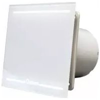
MT-100 - Extraction fan CATA - Free user manual and instructions
Find the device manual for free MT-100 CATA in PDF.

| Product type | In-line extraction fan |
| Brand | CATA |
| Model | MT-100 |
| Duct diameter | 100 mm (MT-100), 125 mm (MT-125) |
| Max distance between suction and discharge | 3 m |
| Power supply | Single-phase, voltage and frequency according to rating plate |
| Required cable type | Rigid two-conductor cable, min. cross-section 1 mm² |
| Double insulation | Yes (no earth connection required) |
| Required switch | All-pole with contact gap ≥ 3 mm |
| Installation | In a rigid or flexible duct of 100 mm |
| Fixing | Hose clamps or wall brackets (plugs and screws) |
| Main functions | Air extraction, ventilation |
| Noise level | Silent (typical value not provided) |
| Maintenance and cleaning | Clean the blades and housing regularly with a damp cloth |
| Safety | Double insulation, emergency stop via all-pole switch |
| Spare parts | Hose clamps, covers, connection terminal block |
| Repairability | Can be disassembled to access electrical connections |
| Approximate weight | ~1 kg |
Frequently Asked Questions - MT-100 CATA
User questions about MT-100 CATA
0 question about this device. Answer the ones you know or ask your own.
Ask a new question about this device
Download the instructions for your Extraction fan in PDF format for free! Find your manual MT-100 - CATA and take your electronic device back in hand. On this page are published all the documents necessary for the use of your device. MT-100 by CATA.
USER MANUAL MT-100 CATA
Operation and maintenance instructions
INSTALLATIE AAN BUIZEN
INSTALLATION IN THE PIPING
For installation of the extractor in the air conduit piping, an opening (A) has to be made in the piping where there is the outlet for the extractor connection cables.
The opening must be long enough so that there is no interference with the cables emerging.
The width of the opening will be equal to or greater than the diameter of the drilling cover trim.
To fix the piping to the extractor, use the clamp flanges (C).
A) This tubular extractor is designed to be installed in a flexible or rigid conduit of 100mm . diameter for the MT-100 and 125mm diameter for the MT-125.
B) The distance between the intake and exhaust openings should not be more than 3m .
C) The extractor (C) is placed between points A and B (intake and exhaust) and fixed to the conduits by clamps that hold it securely in position.
D) It should be placed so that the arrows indicating the direction of the air flow coincide with the direction of intake and exhaust.
MT-100 AND MT-125 WITH SUPPORT BRACKET
The extractor (C) is placed between points A and B (intake and exhaust) and fixed in position using the plugs and screws provided.
60801860
28/2/05
12:39
Pagina 18
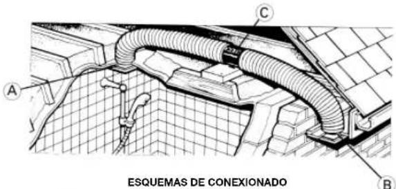
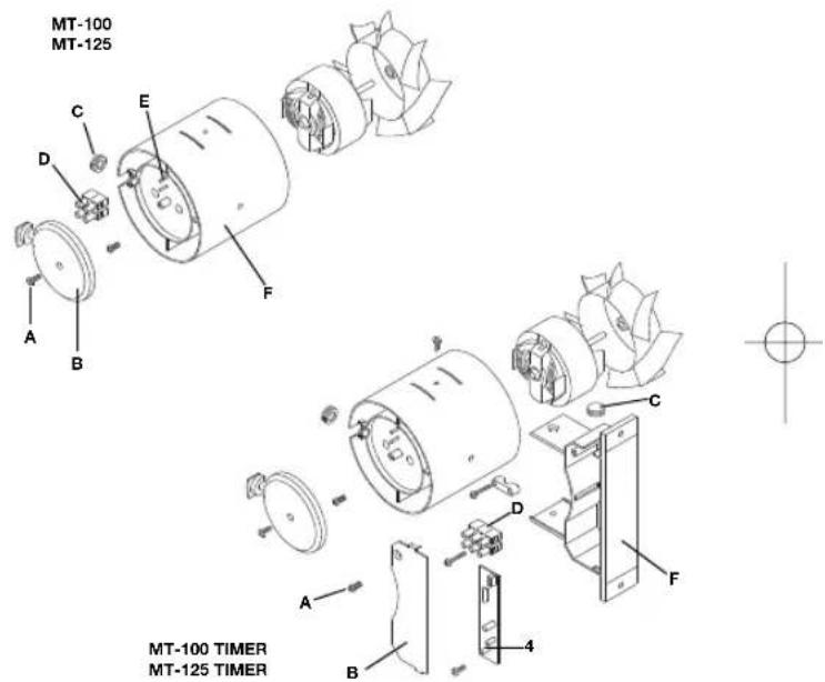
Fig.1
MT-100 MT-125
MT-100 TIMER MT-125 TIMER
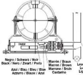
The extractor unit should be connected to a single phase supply network at the voltage and frequency indicated on the extractor characteristics plate.
The electrical installation must be fitted with a single-pole switch with a distance between contacts of at least 3mm
The unit should be connected to the power supply network before being installed in the conduit (MT-100 and MT-125).
1) Loosen the screw (A) and remove the cover (B).
2) Perforate the plug (C) and thread the power cables through the hole.
3) Connect the power cables to the terminals for the connection strip (D) and, once connected fix it firmly between the pivots (E).
4) Insert the plug (C) in the hole between the housing (F) and the cover (B).
5) Replace the cover (B) and fix it in place using the screw (A).
The appliance must be permanently connected to a fixed installation of tubing and power supply cable. (Rigid cable with two conductors of at least 1mm^2 section. It does not require an earth connection as the unit has double insulation).