
Hydro K Pro 500W ATX 2.52 - PC Power Supply FSP - Free user manual and instructions
Find the device manual for free Hydro K Pro 500W ATX 2.52 FSP in PDF.




User questions about Hydro K Pro 500W ATX 2.52 FSP
0 question about this device. Answer the ones you know or ask your own.
Ask a new question about this device
Download the instructions for your PC Power Supply in PDF format for free! Find your manual Hydro K Pro 500W ATX 2.52 - FSP and take your electronic device back in hand. On this page are published all the documents necessary for the use of your device. Hydro K Pro 500W ATX 2.52 by FSP.
USER MANUAL Hydro K Pro 500W ATX 2.52 FSP
natural_image
Abstract geometric logo design with interlocking shapes (no text or symbols)FSP
POWER NEVER ENDS
Power Supply
manual

Installation
At first, remove the old PSU from the system case. Firstly, draw off all plugs from the PSU, that are connected with the mainboard or other components in the PC. Now remove the screws at the back side of the case which connects the PSU with the case. After the screws are removed, remove the old PSU from the case carefully and replace it with your new FSP PSU.
Set the PSU into the intended position in the housing and tighten it with the supplied screws. If you purchased a PSU with modular cables, put all necessary cables on the PSU. No need to connect cables that are not intended to be used on the PSU.
natural_image
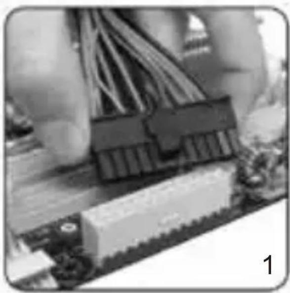
Close-up of electronic circuit board components with visible wiring and connectors (no text or symbols)Put the 20+4 / 24-pin ATX plug through the housing to the correct connection of the mainboard.
natural_image
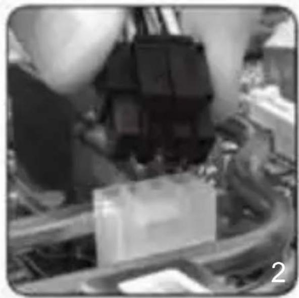
Close-up of mechanical components and wiring (no visible text or symbols)Connect the 8-pin plug to the mainboard. If your mainboard only has a 4-pin connector, then use the 4-pin plug or split the 8-pin connector in half.
natural_image
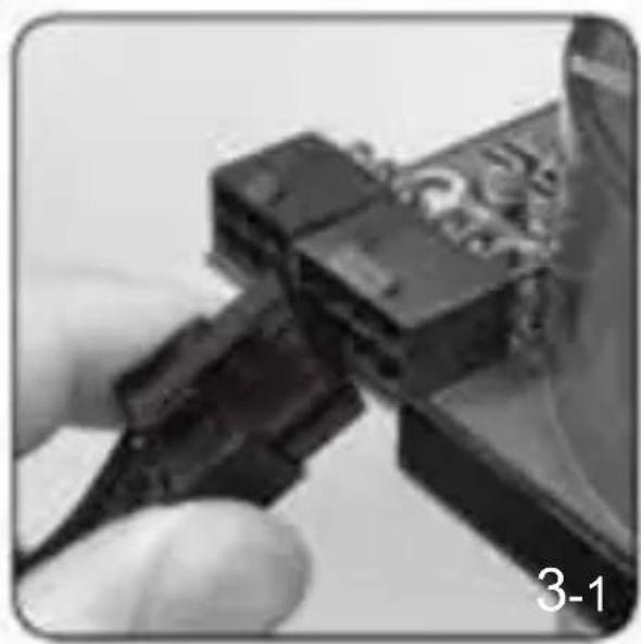
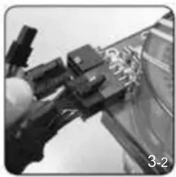
Close-up of a hand holding a black cable with a connector, no visible text or symbolsFor graphic cards with 6-pin connector or connectors, use the suitable cables. Modern graphic cards with 8-pin connectors are also supported. In this case, use the other two pins beside the regular 6-pin plug in order to create an 8-pin connector.
natural_image
Close-up of mechanical components or tools with no visible text or symbols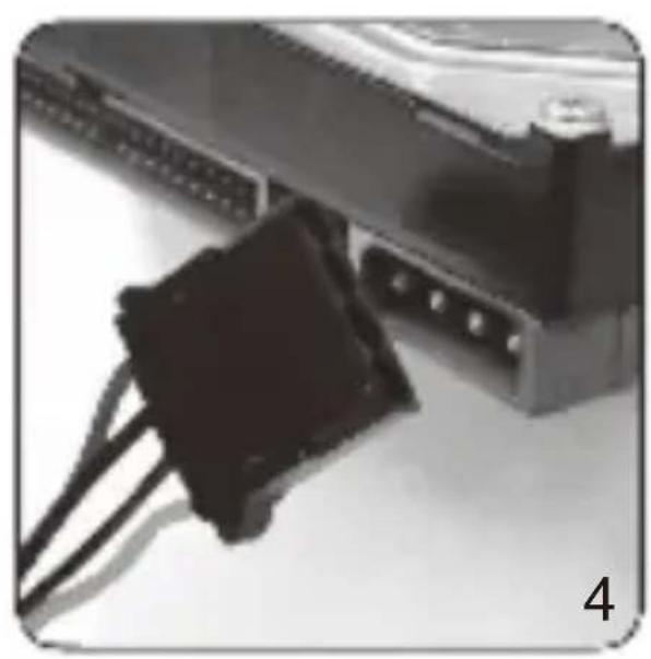
natural_image
Close-up of a black plastic connector attached to a computer interface (no visible text or symbols)Lastly connect the peripheral devices such as hard disks and optical drives with 4-pin Molex-or 15-pin SATA connectors.

Connectors
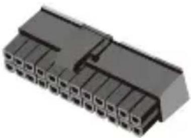
20+4 / 24-pin connection to mainboard (ATX)
natural_image
3D rendering of a black plastic connector with multiple slots and a notch (no text or symbols visible)| Pin 1 | +3.3V | 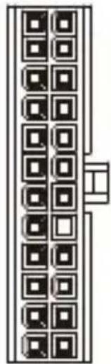 | Pin 13 | +3.3V |
| Pin 2 | +3.3V | Pin 14 | -12V | |
| Pin 3 | GND | Pin 15 | GND | |
| Pin 4 | +5V | Pin 16 | PS-ON | |
| Pin 5 | GND | Pin 17 | GND | |
| Pin 6 | +5V | Pin 18 | GND | |
| Pin 7 | GND | Pin 19 | GND | |
| Pin 8 | PG | NOT CONNECTED | N/C | |
| Pin 9 | +5VSB | Pin 20 | +5V | |
| Pin 10 | +12V | Pin 21 | +5V | |
| Pin 11 | +12V | Pin 22 | +5V | |
| Pin 12 | +3.3V | Pin 23 | GND |
natural_image
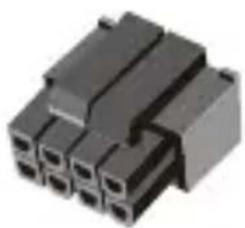
Close-up of a black plastic electrical connector with multiple ports (no visible text or symbols)4+4-pin connection to mainboard (EPS)
| Pin 1 | GND | Pin 5 | +12V | |
| Pin 2 | GND | 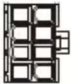 | Pin 6 | +12V |
| Pin 3 | GND | Pin 7 | +12V | |
| Pin 4 | GND | Pin 8 | +12V |
natural_image
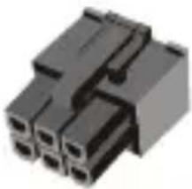
Close-up of a black plastic electrical connector (no visible text or symbols)6-pin connection to graphics card (PCI-E)
| Pin 1 | +12V | Pin 4 | GND | |
| Pin 2 | +12V |  | Pin 5 | GND |
| Pin 3 | +12V | Pin 6 | GND |
natural_image
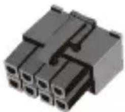
Close-up of a black plastic electrical connector with multiple ports (no visible text or symbols)6+2-pin connection to graphics card (PCI-E)
| Pin 1 | +12V | 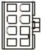 | Pin 5 | GND |
| Pin 2 | +12V | Pin 6 | GND | |
| Pin 3 | +12V | Pin 7 | GND | |
| Pin 4 | GND | Pin 8 | GND |
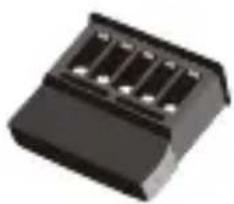
Serial-ATA connection for components (SATA)
natural_image
Black plastic electronic component with four slots (no visible text or symbols)Pin 1 +12V
Pin 2 GND
Pin 3 +5V
Pin 4 GND
Pin 5 +3.3V
natural_image
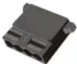
3D rendering of a black plastic electrical connector (no text or symbols visible)4-pin molex connection for components (4P)
Pin 1 +12V
Pin 2 GND
Pin 3 GND
Pin 4 +5V

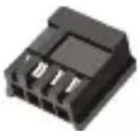
4-pin connector for floppy drives (4P)
Pin 1 +12V
Pin 2 GND
Pin 3 GND
Pin 4 +5V
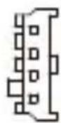
Attention
- Please make sure the modular connector must be connected with flat cable closely.
- If power supply is modular design, please double check the followings:
1) Make sure connectors have been connected until hear "Click"
2) If connectors broken, please stop using and contact with your dealer immediately.
3) It's recommended to check connectors per 6 months.
4) Connectors would be burned or short circuit occurred if connectors loose.
- Warranty does not cover side stickers. Stickers should only be used once.
natural_image
Close-up of electronic components with glowing wires, no visible text or symbols3
Warranty Policy
Thank you for purchasing FSP product!
FSP warrants that the product will be free of defects in material and workmanship, and provides the warranty period-identified on the product package from the power supply on the date of purchase.
In the event that warranty policy might be different in certain regions; please contact local authorized FSP reseller where the product is purchased.
The warranty is applied to damages caused through normal use and is void if it is resulted from, but not limited to, the following situations:
- Wear and tear associated with normal use
- Any modification, abuse, accident, disassembly, misapplication, or unauthorized repair
- Removal of any manufacturer label(s) or sticker(s)
- Any improper operation, including any use not in accordance with any supplied product instructions
- Connection to any improper voltage supply
- Any other cause which does not relate to a product defect in materials or workmanship
4
Trouble Shooting
If the power supply unit fails to function properly, please check the following:
- Is the AC input connected securely and electrical outlet switched out?
- Check that the output connectors are connected properly to all the components.
- Disconnect the power cord from the unit to reset supply unit.
However, if the power supply unit still does not function properly, please contact your original vendor or retailer for repair or replacement.
5
WEEE
ATTENTION!!!
The product contains hazardous waste and/or recycling goods. According to the law it is not allowed to be disposed of in the household waste.
For more detailed information please contact the applicable collection point for hazardous waste or recycling goods.
The product contains hazardous waste and/or recycling goods. According to the law it is not allowed to be disposed of in the household waste. For more detailed information please contact the applicable collection point for hazardous waste or recycling goods.
3
Garantierichtlinie
4 WEEE (Waste Electrical and Electronic Equipment)
FSP TECHNOLOGY INC. (Headquarters)
NO.22, Jianguo E. Rd., Taoyuan Dist.,
Taoyuan City 330, Taiwan.
TEL: +886-3-3577359
FAX: +886-3-3577597
United States Office
FSP Group USA Corp.
14284 Albers Way, Chino, CA 91710, U.S.A.
TEL: +1-909-606-0960
FAX: +1-909-606-0014
E-mail: info@fspgroupusa.com
Germany Office
Fortron/Source (Europa) GmbH
Carl-Friedrich-Benz-Strasse 13, D-47877
Willich, Germany
TEL: +49-2154-894-012-0
FAX: +49-2154-894-012-20
E-mail: sales@fortron-source.de
French Office
FSP Group France
Bat 123A BP625 Zone Juliette, Rue Du Sel,
94392 Orly Aerogare, Cedex France
TEL: + 33(0)1-70-03-60-60
+33(0)1-70-03-60-64
E-mail: contact@fsp-group.fr
commercial@fsp-group.fr
U.K. Office
FSP (GB) LTD.
Unit 8, Curo Park, Frogmore, St. Albans,
Hertfordshire, AL2 2DD, United Kingdom
TEL: +44-1727-873-888
FAX: +44-1727-873-668
E-mail: sales@fspgroup.co.uk
Turkey Office
FSP Technology Inc. İstanbul İrtibat Bürosu
Thank you for purchasing FSP products!
FSP Technology Inc., the world's most respected designer and manufacturer of switching power supply unit(PSU) and mobile power solutions.
| Product Name |
| Date |
| Name |
| Phone |
| Shop |