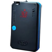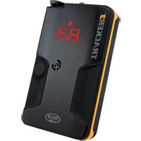
Tracker 3 - Avalanche beacon BCA - Free user manual and instructions
Find the device manual for free Tracker 3 BCA in PDF.


User questions about Tracker 3 BCA
0 question about this device. Answer the ones you know or ask your own.
Ask a new question about this device
Download the instructions for your Avalanche beacon in PDF format for free! Find your manual Tracker 3 - BCA and take your electronic device back in hand. On this page are published all the documents necessary for the use of your device. Tracker 3 by BCA.
USER MANUAL Tracker 3 BCA
flowchart
graph TD
    A["8.3 (↑)"] --> B["Direction Lights"]
    B --> C["Directional indicators"]
    C --> D["Distance Indicator/Battery Power Display"]
    D --> E["Distance Indicator/Battery Power Display"]
    E --> F["Distance Indicator/Battery Power Display"]
    F --> G["Distance Indicator/Battery Power Display"]
    G --> H["Distance Indicator/Battery Power Display"]
    H --> I["Distance Indicator/Battery Power Display"]
    I --> J["Distance Indicator/Battery Power Display"]
    J --> K["Distance Indicator/Battery Power Display"]
    K --> L["Distance Indicator/Battery Power Display"]
    L --> M["Distance Indicator/Battery Power Display"]
    M --> N["Distance Indicator/Battery Power Display"]
    N --> O["Distance Indicator/Battery Power Display"]
    O --> P["Distance Indicator/Battery Power Display"]
    P --> Q["Distance Indicator/Battery Power Display"]
    Q --> R["Distance Indicator/Battery Power Display"]
    R --> S["Distance Indicator/Battery Power Display"]
    S --> T["Distance Indicator/Battery Power Display"]
    T --> U["Distance Indicator/Battery Power Display"]
    U --> V["Distance Indicator/Battery Power Display"]
    V --> W["Distance Indicator/Battery Power Display"]
    W --> X["Distance Indicator/Battery Power Display"]
    X --> Y["Distance Indicator/Battery Power Display"]
    Y --> Z["Distance Indicator/Battery Power Display"]
    Z --> AA["Distance Indicator/Battery Power Display"]
    AA --> AB["Distance Indicator/Battery Power Display"]
    AB --> AC["Distance Indicator/Battery Power Display"]
    AC --> AD["Distance Indicator/Battery Power Display"]
    AD --> AE["Distance Indicator/Battery Power Display"]
    AE --> AF["Distance Indicator/Battery Power Display"]
    AF --> AG["Distance Indicator/Battery Power Display"]
    AG --> AH["Distance Indicator/Battery Power Display"]
    AH --> AI["Distance Indicator/Battery Power Display"]
    AI --> AJ["Distance Indicator/Battery Power Display"]
    AJ --> AK["Distance Indicator/Battery Power Display"]
    AK --> AL["Distance Indicator/Battery Power Display"]
    AL --> AM["Distance Indicator/Battery Power Display"]
    AM --> AN["Distance Indicator/Battery Power Display"]
    AN --> AO["Distance Indicator/Battery Power Display"]
    AO --> AP["Distance Indicator/Battery Power Display"]
    AP --> AQ["Distance Indicator/Battery Power Display"]
    AQ --> AR["Distance Indicator/Battery Power Display"]
    AR --> AS["Distance Indicator/Battery Power Display"]
    AS --> AT["Distance Indicator/Battery Power Display"]
    AT --> AU["Distance Indicator/Battery Power Display"]
    AU --> AV["Distance Indicator/Battery Power Display"]
    AV --> AW["Distance Indicator/Battery Power Display"]
    AW --> AX["Distance Indicator/Battery Power Display"]
    AX --> AY["Distance Indicator/Battery Power Display"]
    AY --> AZ["Distance Indicator/Battery Power Display"]
    AZ --> BA["Distance Indicator/Battery Power Display"]
    BA --> BB["Distance Indicator/Battery Power Display"]
    BB --> BC["Distance Indicator/Battery Power Display"]
    BC --> BD["Distance Indicator/Battery Power Display"]
    BD --> BE["Distance Indicator/Battery Power Display"]
    BE --> BF["Distance Indicator/Battery Power Display"]
    BF --> BG["Distance Indicator/Battery Power Display"]
    BG --> BH["Distance Indicator/Battery Power Display"]
    BH --> BI["Distance Indicator/Battery Power Display"]
    BI --> BJ["Distance Indicator/Battery Power Display"]
    BJ --> BK["Distance Indicator/Battery Power Display"]
    BK --> BL["Distance Indicator/Battery Power Display"]
    BL --> BM["Distance Indicator/Battery Power Display"]
    BM --> BN["Distance Indicator/Battery Power Display"]
    BN --> BO["Distance Indicator/Battery Power Display"]
    BO --> BP["Distance Indicator/Battery Power Display"]
    BP --> BQ["Distance Indicator/Battery Power Display"]
    BQ --> BR["Distance Indicator/Battery Power Display"]
    BR --> BS["Distance Indicator/Battery Power Display"]
Disclaimer
No avalanche transceiver can help save lives without a fully trained user. Practice frequently with your Tracker3 before going into the backcountry. Learn and understand the inherent dangers of backcountry travel. Become educated in avalanche hazard evaluation, route selection, and self-rescue. In addition to your transceiver, always carry a probe and shovel—and always travel with a partner. We also recommend the use of avalanche airbags and group communication devices, such as two-way radios.
Make sure all rescue equipment is functioning properly before venturing into the backcountry. Perform a transceiver trailhead test every time you use your Tracker3. Check that all transceivers transmit and receive properly—and that all receive a signal at a minimum distance of 20 meters (65 feet).
Do not place cellular phones, communication radios, GPS devices, digital cameras, or any other electronic equipment within 50 cm (20 inches) of Tracker3 while performing a transceiver search. In receive mode, irregular readings, decreased range and multiple burial indications can be caused by these and other sources of electrical interference, such as power lines, electrical storms, and electrical generating equipment. In transmit mode, keep Tracker3 at least 20 cm (8 inches) from other electronic equipment or large metal objects. Use only alkaline batteries of identical age and brand. Do not use rechargeable, lithium, Oxyride, PowerPix, or any other non-alkaline battery.
This owner's manual covers the basic techniques required to use Tracker3 effectively. To increase your efficiency, refer to our website: www.backcountryaccess.com. Here you will also find important resources for obtaining avalanche education and updates on regional avalanche conditions.
To ensure warranty protection and to be notified of software updates, please complete an online warranty registration at: www.backcountryaccess.com/warranty.
Conforms to the R&TTE harmonized version of the EN 300 718 and meets or exceeds the requirements of Articles 3.1, 3.2, and 3.3.
Avalanche Awareness
This is a basic introduction to avalanche safety and awareness. We encourage you to read this manual thoroughly. We strongly suggest taking an avalanche course in your area before venturing into the backcountry.
Before leaving, call your local avalanche forecast center and determine the danger level in the area you intend to visit.
U.S. www.avalanche.org
Canada www.avalanche.ca
Europe www.lawinen.org
Figure B
Avalanche Forecasts
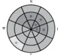

Low

Moderate

Considerable

High

Extreme

Pockets of next danger level
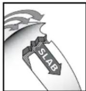
Bulletins from your local avalanche forecast center will enable you to identify the avalanche problems to avoid when planning your route.
Avalanche Awareness
At the trailhead, check that each person has a working transceiver, probe, and shovel—and knows how to use them. We also recommend the use of avalanche airbags and two-way radios.
Learn to recognize avalanche terrain:
- Does this slope have a history of sliding?
• What is the angle and aspect of the slope? - Will recent weather impact snow stability?
Learn to avoid avalanche terrain:
• Is there any evidence of recent avalanche activity?
• Is the slope angle between 30 and 45 degrees?
- Does the slope you plan to use have dangerous terrain traps (rocks, trees, gullies, cliffs, etc.)?
Avalanche Awareness
Familiarization
Travel with considerate partners:
• Cross potentially dangerous terrain one at a time.
- Identify and practice stopping in safe zones.
- Have an escape route in mind if the slope does avalanche.
- Communicate with your partners before moving on to the slope.
When traveling in a group, be aware of the errors groups typically make:
- Recreating at an area that's been visited without incident before and feeling confident in its stability.
- Not speaking out or communicating concerns about a path or slope, fearing conflict.
- Being overconfident in the groups' abilities.
- Determination to reach a destination without re-evaluating terrain and conditions.
If in doubt, it is always best to avoid questionable terrain and return when the snow is stable.
If you are caught in an avalanche:
- Yell "avalanche" and wave your arms to alert your group.
- Deploy your avalanche airbag if you have one.
- Try to escape the slide by grabbing trees or rocks or "swimming" to the side.
- Try to keep your airway clear of snow.
- When you feel the slide slowing, thrust a hand upward in hopes of it being seen.
- Place your other hand in front of your face to increase the air space.
- Remain calm, breathe slowly and conserve your air.
Searching for victims:
- Do not go for help! You are the victim's only chance of survival!
- Establish a last seen point.
- Confirm you are not in danger of a second avalanche occurring.
- Look for visual clues to the victim's location.
- Begin your signal search for the victim using your avalanche transceiver.
Thank you for choosing Tracker3, featuring Tracker2's famous ease-of-use in a smaller, lighter package.
Remember, transceiver searches are only part of the avalanche rescue process. It is equally important to practice the probing and shoveling techniques found later in this section. For training videos on transceiver searching, probing, and strategic shoveling techniques, please visit www.backcountryaccess.com/education.
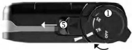
Transmit mode: From the 'Off' position, pull the sliding lock ⑤ in the direction of the arrow and turn the dial switch ① on top of Tracker3 to the transmit ("TR") position (see Figure C).
Figure C
Top view of Tracker3.
text_image
① SE TR OFF ⑤The battery life is then shown in the distance/battery power display ② in Figure A.
After displaying battery power, Tracker3 flashes "TR" and enters transmit mode. The transmit light ③ flashes with every transmit pulse. This light will not flash if the battery power is below 20 percent.
In addition to being displayed at startup, the battery power level can also be checked in transmit mode by pressing the Options button ⑥.
Note: the battery percentage is approximate. Replace batteries ④ before reaching 40 percent.
When in transmit mode, the Tracker3 cannot be turned to off or search without pulling back the sliding lock.
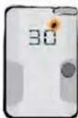
Search mode: Pull the sliding lock ⑤ and rotate the dial switch to the search ("SE") position. In search mode, the display will periodically flash "SE" until a signal is detected. Upon detecting a transmitting signal, Tracker3 will begin to display distance and directional readings. At distances of less than two meters, the directional lights are no longer shown.
Return to transmit: When in search mode, the sliding lock does not need to be moved in order to return to transmit mode. Simply rotate the switch back to the transmit position. The Tracker will beep and flash "TR" before it begins to transmit.
Familiarization
Familiarization
After 30 minutes in search mode, Tracker3 will beep every two minutes. After 12 hours in transmit mode, it will beep every two minutes. These beeps are reminders that there has been no user input and Tracker3 is still on.
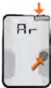
Auto Revert Mode: Auto revert mode will make your Tracker3 automatically revert to TR (transmit) mode if the device does not move for one minute—or if there is movement, but the searcher remains in search mode for more than five minutes. An alarm will sound 30 seconds before the unit returns to transmit mode. This can be avoided by pressing the Options button or turning the dial switch before the 30-second warning period has elapsed.
Auto revert mode is activated by holding down the Options button while turning on the device, in either transmit or search mode. You must continue to hold down the Options button until "Ar" is shown on the display.
Before "Ar" is shown, other diagnostics will be displayed, including "T3," "r.c." (with software version number) and battery power percentage.
If choosing to use auto revert, it must be activated every time the unit is turned on. Otherwise, the unit can only be switched from search to transmit mode manually.
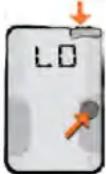
Muting the Sound: The sound in Search mode can be muted by pressing the Options button while switching from transmit to search mode. "LO" will appear in the display and all sounds assisting the search function are muted.
Downloading Tracker3 software: Using BCA software, you can update the Tracker3's programming. Currently this is only possible with a PC (not Mac). To update:
- Go to www.backcountryaccess.com/downloads;
- Download T3 Utility program;
- Install and start the program;
- Connect the Tracker3 to your computer with a standard USB cable;
- Follow the T3 Utility instructions.
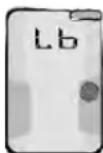
Low battery warning: At 40 percent battery power, the audible sounds at startup will no longer be heard. At 20 percent, no sounds will be heard in search mode.
When the battery power becomes too low to operate, the transceiver will display the "Lb" sign. When you see this,
replace the batteries before further use. When batteries are too low to do startup routines, a simple "0" will blink on the display.
Mismatched batteries can act unpredictably at various temperatures and low batteries can die unexpectedly fast. Therefore, we strongly recommend changing batteries once the battery power indicator reaches 40 percent.
NOTE: never mix new and used batteries in your transceiver-or batteries of mixed brands. Never use lithium or rechargeable batteries. These may all lead to an inaccurate battery power indication.
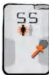
Signal Suppression: Signal Suppression mode suppresses the strongest signal and shows the searcher the second strongest signal, including directional arrows. Always stay in standard search mode when searching for the first transmitter. Once the first victim has been located and your fine search is complete, you are ready to use Signal Suppression.
Signal Suppression mode is activated by pressing the Options button until "SS" is shown on the display. To enter suppression mode, the Options button must be released before "BP" is displayed. The multiple victim icon will flash alternately while in SS mode.
Suppression of the strongest signal will last for one minute, giving the searcher time to move away from the suppressed signal and lock on to the next transmitter. The Tracker3 will automatically default from suppression mode to standard search mode after one minute. This can also be done manually, by pressing the Options button until "SE" is displayed. When returning to search mode, the multiple victim icon will stop flashing and the Tracker3 will isolate the strongest signal.
NOTE: Signal suppression can be unreliable when attempting to suppress older analog transceivers.
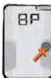
Big Picture: Big Picture mode is the closest thing to an analog transceiver in the digital world. It displays distances and directions of all the transceivers that are transmitting within range. With Big Picture mode, you can estimate how many transceivers are in the search area along with their approximate direction. You can also perform a search in BP mode, but always remember to return to normal search mode
during the fine search when you're getting close to the victim.
Big Picture mode is activated by holding down the Options button until "BP" flashes in the display. You must continue to hold down the Options button to stay in BP mode. Once the mode button is released, the Tracker3 will automatically return to search mode and isolate the strongest signal.
Familiarization
Adjustment/Fitting
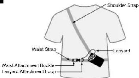
Tracker3 can be worn with or without its harness. When used with a harness, Tracker3 should be worn underneath your outer garments, as shown in Figure D.
Figure D
text_image
Shoulder Strap Waist Strap Lanyard Waist Attachment Buckle Lanyard Attachment LoopDistance/directional display should be against your body and transmit light should be exposed and visible.
To search, remove Tracker3 from its pouch, but keep the harness on and lanyard attached. If using without a harness, keep Tracker3 in a secure pocket, preferably in your pants or other garment that won't be removed while traveling in the backcountry. Attach the lanyard clip to a zipper or other solid fixture. If the lanyard is removed from harness or clothing for searching, keep it attached to your wrist with the loop provided.
Power Supply
Tracker3 operates with three AAA alkaline batteries. Use only high-quality alkaline batteries of identical age and brand. Do not use rechargeable, lithium, Oxyride, PowerPix or any other non-alkaline battery. Replace with fresh batteries at the beginning of every season.
If Tracker3 is exposed to excessive moisture, open the battery door④ to help allow the unit to dry. To prevent corrosion of contacts, remove batteries during extended periods of inactivity. The manufacturer does not warranty damage caused by battery corrosion.
Trailhead Test
To ensure proper transmit and search functions, always perform a trailhead test before starting your tour. One person should walk 20 meters away and make sure his or her signal is detected by the others. Then the rest of the group switches to transmit mode and walks toward the leader, who should confirm their signals can each be detected from 20 meters away. The leader should always switch back to transmit mode after the test is completed.
Operating Instructions
Searching
Tracker3 operates using the 457 kHz international standard frequency. It is fully compatible with all avalanche transceivers adhering to this standard. Do not use with 457 kHz transceivers designed for firefighter rescue.
When searching, keep Tracker3 at least 20" (50 cm) away from electrical equipment, including cell phones and video cameras. Turn all non-essential electrical equipment off if possible.
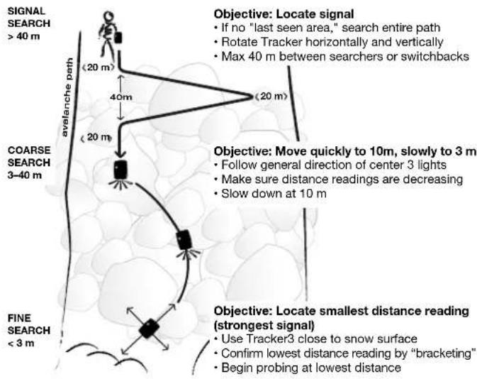
The search process includes four phases: the signal search, the coarse search, the fine search, and the pinpointing/probing phase (See Figure E).
Figure E
flowchart
graph TD
A["SIGNAL SEARCH > 40 m"] --> B["AVELANCHÉ PETH"]
B --> C["AVELANCHÉ PATH"]
C --> D["COARSE SEARCH 3–40 m"]
D --> E["FINE SEARCH < 3 m"]
E --> F["Objective: Locate signal\n• If no "last seen area," search entire path\n• Rotate Tracker horizontally and vertically\n• Max 40 m between searchers or switchbacks"]
F --> G["Objective: Move quickly to 10m, slowly to 3 m\n• Follow general direction of center 3 lights\n• Make sure distance readings are decreasing\n• Slow down at 10 m"]
G --> H["Objective: Locate smallest distance reading (strongest signal)\n• Use Tracker3 close to snow surface\n• Confirm lowest distance reading by "bracketing"\n• Begin probing at lowest distance"]
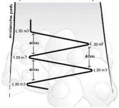
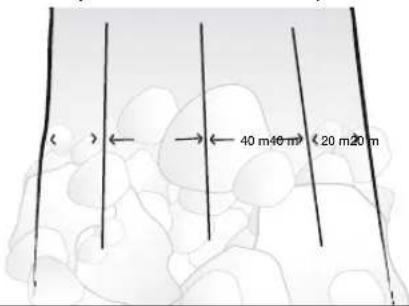
Signal Search: The signal search refers to the process of establishing a search pattern and looking for a signal. The search pattern will be defined by the victim's last seen area, the size of the slide, and the number of searchers. Refer to Figure F to establish a signal search pattern. If the slide is less than 40 meters wide, the signal search path will be directly up or down the center. If the victim's last seen area is well defined, the signal search will follow a direct path along the fall line (up or down) from this point.
Operating Instructions
Operating Instructions
Figure F
Signal search path with one searcher (slide wider than 40 meters).
text_image
avalanche path (20 m) 40m (20 m) 40m (20 m) (20 m)Signal search path with multiple searchers (slide wider than 40 meters).
text_image
( )←→← 40 m 40 m) < 20 m 20 mIf the slide is wider than 40 meters and there is no last seen point, cover the entire slide area by using switchbacks in the search pattern (Figure F). If multiple rescuers are available, establish a search pattern where the space between searchers is no more than 40 meters and the distance to the edges is no more than 20 meters.
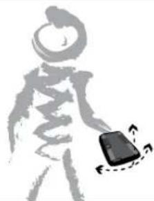
Prior to the signal search, be sure that all transceivers are turned to search mode. Rotate Tracker3 slowly in all directions (Figure G) while moving along your signal search pattern. While searching, be aware of other physical clues, such as equipment or extremities protruding from the snow surface. When no signal is detected, "SE" will flash in the distance indicator. Once a signal is detected consistently, mark this spot and begin the coarse search.
Figure G
Slowly rotate the Tracker horizontally and vertically in your hand, but move rapidly during the signal search. Do not abandon your search path until you have captured a strong, steady signal. Ignore irregular signals, which can sometimes be caused by electrical interference.
natural_image
Silhouette of a person holding a small object with motion arrows, no text or symbols presentCoarse Search: The coarse search is the portion of the search from where you have detected a steady signal to where you are close to the victim.
Once the signal is consistently detected, rotate Tracker3 slowly on a horizontal plane until the center direction light ⑦ is blinking.
Tracker3 is now pointed in the direction of the strongest signal. The four lights on either side of center tell you which way to rotate Tracker3 to engage the center light. The distance indicator ② tells you, in approximate meters, how far you must travel (1 meter = 1.1 yards or 3.3 feet). If the number on the distance indicator is increasing, you are on the same axis as the victim's signal, but moving in the opposite direction. Turn 180 degrees, engage the center search light again, and continue your search in the direction Tracker3 is pointing. If you are stationary, but the distance is significantly changing, you are probably detecting the signal of another rescuer. Make sure all rescuers are in search mode before continuing.
You may find that, while following the directional lights, your route follows an arc. This is because Tracker3 follows the shape of the electromagnetic signal coming from the transmitting transceiver's antenna. The distance displayed is the distance to be traveled along that signal, not the straight-line distance from you to the victim.
Operating InstructionsOper
Fine Search: The fine search is the final part of the transceiver search, which is performed on foot with the transceiver positioned at or near the snow surface. The objective of the fine search is to locate where the signal is strongest (distance reading is lowest) and to reduce the area to be probed.
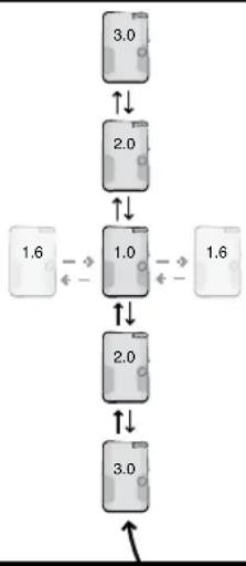
Move Tracker3 slowly in a straight line along the surface of the snow during the final three meters of the fine search. The directional lights do not illuminate in the final two meters, so only pay attention to the distance readings. From the point where you have located the smallest reading, "bracket" at 90-degree angles to the left and then to the right in search of a lower reading (Figure H). Repeat if necessary along both axes. Begin probing at the lowest distance reading.
Pinpointing/Probing
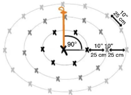
At your lowest distance reading, probe in concentric circles, with each probe hole about 10 inches (25 cm) apart (Figure I). Your probe should enter the snow perpendicular to the slope. Once you have confirmed the victim's location, leave the probe in the snow.
Figure I
text_image
25 10" 90° 10" 10" 25 cm 25 cmFigure H
Bracketing: Make sure you go well past the low reading to confirm it is the lowest. When bracketing, ignore the directional lights, which no longer illuminate at less than two meters. Do not rotate the transceiver during this process, as it can change the distance readings.
flowchart
graph TD
    A["1.6"] --> B["2.0"]
    B --> C["1.0"]
    C --> D["2.0"]
    D --> E["3.0"]
    E --> F["1.6"]
    style A fill:#f9f,stroke:#333
    style B fill:#f9f,stroke:#333
    style C fill:#f9f,stroke:#333
    style D fill:#f9f,stroke:#333
    style E fill:#f9f,stroke:#333
    style F fill:#f9f,stroke:#333
Shoveling
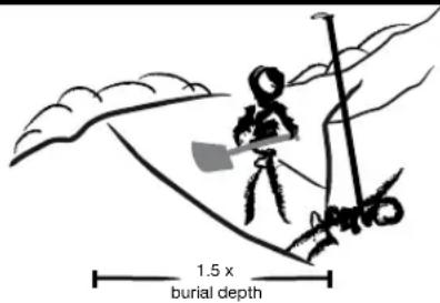
Shoveling is difficult and consumes the majority of time during an avalanche rescue. For best results, start shoveling just downhill of the probe (Figure J). Make sure your hole is at least one "wingspan" wide. In burials deeper than one meter, excavate downhill about 1.5 times the burial depth.
Figure J
text_image
1.5 x burial depthMultiple Burials
When more than one transmitting victim is within the receiving range of Tracker3, the multiple burial icon ⑧ will illuminate and stay solid. (Note: this icon can occasionally illuminate irregularly in the presence of electromagnetic noise or when detecting older analog transceivers). If there are more than two transmitting victims within range, then the "+" icon will illuminate.
If the multiple burial icon is illuminated and/or Tracker3 displays more than one distance and direction, then there are probably several victims within range. Stay in search mode and focus on the closest distance reading, attempting to engage that signal in the center search light.
Once you are significantly closer to one signal than the other, Tracker3 will "lock" onto that signal and mask out the others. Once this signal is isolated, Tracker3 will behave very similar to how it does in a single transceiver search. Once you have located and excavated the first victim, turn his or her transceiver off if you determine the conditions are safe. If you have a clear signal, then begin searching for the next victim.
If it is not possible to turn off the first victim's transceiver—and you have enough people to begin shoveling—then we recommend isolating the next signal using Signal Suppression.
Operating Instructions
Operating Instructions
Isolating multiple victims: Complex multiple burials are rare in recreational settings and usually can be treated as a series of single burials performed in normal search mode. The only time multiple burials can become truly complex is when it's not possible to turn off the first victim's transceiver, when the victims are in close proximity ( ≤ 10 m) to each other, or if there are three or more victims.
The following icons help to determine how many buried victims are within range of the rescuer and whether they are in close proximity to each other:
| More than one signal within range. | Two victims both within six meters of the searcher. | More than two signals within range. | More than two signals within range and at least two within six meters. |
If it's not possible to turn off a victim's transceiver, use Signal Suppression to find the next closest victim. Press and immediately release the Options button (6). "SS" will be shown in the display and the icons in the multiple burial indicator will flash back and forth. Follow the distance and direction to the next victim. Remember that the first victim's signal will be suppressed for one minute, at which time the icons in the multiple burial indicator will stop flashing. To go back to normal search mode before one minute has elapsed, simply press the Options button.
It is important to note that Signal Suppression, marking, and other forms of signal isolation are not 100 percent reliable, especially when searching for older analog transceivers. This is due to the possibility of overlapping signals, especially when more than two transmit signals are within range. Due to their imprecise transmit signals, analog transceivers can sometimes trigger multiple burial indications. For these reasons, it's important to learn some of the backup techniques described at www.backcountryaccess.com/tracker-resources.
Using Big Picture Mode: Big Picture mode is a valuable feature that can be used to gain an overview of the scenario and optimize the efficiency of your search. It can be used at the beginning of a scenario to assign rescuers to each displayed signal. It is also valuable in situations involving more than two signals within range.
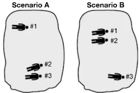
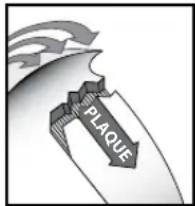
Remember, Tracker3 suppresses only one signal at a time. When you suppress a second signal, it will then show you the next closest signal—even if that victim's signal was suppressed earlier. If victim #3 is closer to victim #2 than victim #1 (scenario A, below), then suppressing victim #2's signal will take you to victim #3 automatically. However, if victim #1 is closer than victim #3, (scenario B), Tracker3 will bring you back to victim #1. If this is the case, use Big Picture mode to find the general direction to the third signal. After moving closer to the third signal, release the Options button and Tracker3 will automatically isolate that third signal.
Figure K
Tracker3 suppresses one signal at a time. When suppressing victim #2's signal, if victim #3 is further away from victim #2 than #1 (scenario B), then use Big Picture mode to move toward #3.
text_image
Scenario A #1 #2 #3 Scenario B #1 #2 #3text_image
N NW NO W O SW SO S 5 4 3 2 1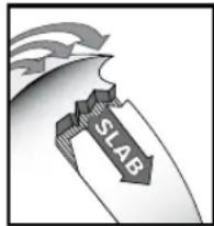
text_image
SLABnatural_image
Silhouette of a person holding a smartphone with motion arrows (no text or symbols)text_image
N NE O E SE S SO NO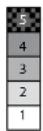
text_image
PLAQUEnatural_image
Silhouette of a human figure holding a small object with motion arrows, no text or symbols presenttext_image
NW W SW S O NO S 4 3 2 1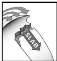
text_image
SLABnatural_image
Silhouette of a human figure holding a small object with motion arrows (no text or symbols)text_image
Scenario A #1 #2 #3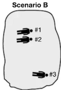
text_image
Scenario B #1 #2 #3text_image
N NW W SW S O NO S SO 5 4 3 2 1
text_image
SLABnatural_image
Silhouette of a person holding a device with motion arrows indicating movement (no text or symbols)text_image
Caso A #1 #2 #3 Caso B #1 #2 #3TRACKER3™
Appendix
Declaration of Conformity
according to ISO/IEC Guide 17050-1:2004
Manufacturer: Backcountry Access, Inc.
2820 Wilderness Place, Unit H
Boulder, CO 80301
USA
Date: 7.12.2013
Declares that the product: Tracker3, 457 kHz Avalanche Rescue Transceiver meets or exceeds all essential requirements and other relevant provisions of the R&TTE Directive 1999/5/EC, including Articles 3.1a, 3.1b, 3.2, and 3.3e and the harmonized standards.
The Declaration of Conformity can be found at the following address: www.backcountryaccess.com/certification

Bruce McGowan
General Manager, Backcountry Access, Inc.
2820 Wilderness Place, Unit H
Boulder, CO 80301
USA
Datum: 07.12.2013
Fabricant: Backcountry Access, Inc. 2820 Wilderness Place, Unit H Boulder, CO 80301 USA
Dated: 7.12.2013
Technical Specifications
• Frequency: 457 kHz
- Batteries: Three AAA/LR03 alkaline batteries. Do not use rechargeable, lithium, Oxyride, PowerPix or any other non-alkaline battery.
- Battery life: minimum 1 hour in search mode after 200 hours in transmit mode (approximately 250 hours in transmit only or 50 hours in search only)
- Search strip width: 50 meters
• Weight: 5.8 ounces (165 grams) without strap and batteries
- Size: 4.6" x 2.8" x 0.9" (11.6 cm x 7.1 cm x 2.3 cm)
- Minimum temperature range (at 66.7 percent battery power): transmit mode: -20°C to +40°C (-4°F to 104°F); search mode: -20°C to +40°C (-4°F to 104°F)
• U.S. Patent number 6,167,249 & 6,484,021 B1
FCC ID: OUNT3 Model No.: Tracker3 IC: 3561A-Tracker3
This device complies with part 15 of the FCC Rules. Operation is subject to the following two conditions:
- This device may not cause harmful interference, and
- This device must accept any interference received, including interference that may cause undesired operation.
Note: This equipment has been tested and found to comply with the limits for a Class B digital device, pursuant to part 15 of the FCC Rules. These limits are designed to provide reasonable protection against harmful interference in a residential installation. This equipment generates, uses and can radiate radio frequency energy and, if not installed and used in accordance with the instructions, may cause harmful interference to radio communications. However, there is no guarantee that interference will not occur in a particular installation. If this equipment does cause harmful interference to radio or television reception, which can be determined by turning the equipment off and on, the user is encouraged to try to correct the interference by one or more of the following measures:
- Reorient or relocate the receiving antenna.
- Increase the separation between the equipment and receiver.
- Connect the equipment into an outlet on a circuit different from that to which the receiver is connected.
- Consult the dealer or an experienced radio/TV technician for help.
Caution: Any changes or modifications not expressly approved by the party responsible for compliance could void the user's authority to operate this device.
This device complies with Industry Canada licence-exempt RSS standard(s). Operation is subject to the following two conditions:
- This device may not cause interference, and
- This device must accept any interference, including interference that may cause undesired operation of the device."
CE
Warranty Information
Warranty Information
Limited Warranty
Backcountry Access, Inc. (BCA) warrants that for a period of five (5) years from the date of purchase, this product will be free from defects in material and workmanship. Should a defect occur during the five (5) year warranty period, BCA will repair or replace the defective product or component part at its option, free of charge. BCA will repair or replace the product with an identical or reasonably equivalent product, at its election, or it may elect to refund the purchase price (less reasonable depreciation based on actual use) if it cannot readily and quickly provide a replacement. Replacement products provided pursuant to this warranty are under warranty only for the remainder of the original warranty period.
This warranty is valid for the original retail purchaser from the date of initial retail purchase and is not transferable. Keep the original sales receipt. Proof of purchase is required to obtain warranty performance. If the original proof of purchase cannot be provided, BCA will use the product's manufacture date as the start of the warranty period. BCA dealers do not have the right to alter, modify or in any way change the terms and conditions of this warranty.
Limitations
This warranty shall not apply if the product (a) is altered, modified, or tampered with in any way by anyone or (b) is damaged by negligence, accident, unreasonable/abnormal use or by other causes unrelated to defective materials or workmanship. Further, the warranty does not cover Acts of God, such as fire, flood, hurricanes and tornadoes.
BCA SHALL NOT BE LIABLE FOR DEATH OR INJURIES TO PERSONS, DAMAGE TO PROPERTY, OR FOR ANY INCIDENTAL, CONTINGENT, OR CONSEQUENTIAL DAMAGES CAUSED BY THE BREACH OF ANY EXPRESS OR IMPLIED WARRANTY. BCA'S SOLE LIABILITY FROM THIS WARRANTY IS LIMITED TO REPAIR OR REPLACEMENT OF DEFECTIVE PRODUCT. EXCEPT TO THE EXTENT PROHIBITED BY APPLICABLE LAW, ANY IMPLIED WARRANTY OF MERCHANTABILITY OR FITNESS FOR A PARTICULAR PURPOSE IS LIMITED IN DURATION TO THE DURATION OF THE ABOVE WARRANTY. SOME STATES, PROVINCES OR JURISDICTIONS DO NOT ALLOW THE EXCLUSION OR LIMITATION OF INCIDENTAL OR CONSEQUENTIAL DAMAGES OR LIMITATIONS ON HOW LONG AN IMPLIED WARRANTY LASTS, SO THE ABOVE LIMITATIONS OR EXCLUSION MAY NOT APPLY TO YOU. THIS WARRANTY GIVES YOU SPECIFIC LEGAL RIGHTS, AND YOU MAY ALSO HAVE OTHER RIGHTS THAT VARY FROM STATE TO STATE OR PROVINCE TO PROVINCE.
How to Obtain Warranty Service
Prior to the expiration of the five (5) year warranty period, obtain a Return Authorization (RA) number and instructions directly from BCA by clicking here: http://www.backcountryaccess.com/customer-service/warranty-service/
If you have questions, contact the BCA warranty service department at (800) 670-8735 or warranty@backcountryaccess.com.
The purchaser is responsible for shipping and handling charges to the BCA warranty service department. BCA will return the repaired or replacement product at its expense, but if it is determined that there is no defect or that the defect resulted from causes not within the scope of this warranty, storage or return of the product will be at the purchaser's expense.
Garantieinformationen
Backcountry Access, Inc.
2820 Wilderness Place, Unit H
Boulder, Colorado USA
Phone: 303-417-1345
info@backcountryaccess.com
www.backcountryaccess.com
BCA/K2 Europe
K2 Sports Europe GmbH
1 Westside Dr. Unit #7
Etobicoke, ON
M9C 1B2
Phone, local: 416-620-4125
Phone, toll free: 866-455-2748
bca@k2canada.com
BCA/Madshus AS
Madshus AS
Industriveien 29
2936 Biri
P: 61134300
M: madshus@madshus.com
BCA/K2 Japan
TMM Bldg.6F,
1-10-5, Iwamoto-Cho, Chiyoda-Ku,
Tokyo Japan 101-0032
Phone (+81)3-6858-2311
BCA@k2japan.com