
PRX-SMP-15X10 - Mounting bracket Middle Atlantic - Free user manual and instructions
Find the device manual for free PRX-SMP-15X10 Middle Atlantic in PDF.

| Product Type | Sliding Wall Mount Bracket |
| Brand | Middle Atlantic |
| Model | PRX-SMP-15X10 |
| Maximum Supported Weight | 6.8 kg (15 lbs) |
| Fixation | On drywall (3/8 to 5/8 inch thick) |
| Material | Reinforced Steel |
| Mounting Type | Wall mounting with sliding plate for extraction |
| Locking System | Lever lock with safety clip |
| Provided Accessories | Drywall anchors, screws, lever lock |
| Maintenance | Clean with a dry cloth |
| Safety | Do not exceed maximum weight; comply with local electrical codes for grounding |
| Intended Use | Support for lightweight audiovisual equipment up to 6.8 kg |
Frequently Asked Questions - PRX-SMP-15X10 Middle Atlantic
User questions about PRX-SMP-15X10 Middle Atlantic
0 question about this device. Answer the ones you know or ask your own.
Ask a new question about this device
Download the instructions for your Mounting bracket in PDF format for free! Find your manual PRX-SMP-15X10 - Middle Atlantic and take your electronic device back in hand. On this page are published all the documents necessary for the use of your device. PRX-SMP-15X10 by Middle Atlantic.
USER MANUAL PRX-SMP-15X10 Middle Atlantic
Thank you for purchasing the Proximity Series Sliding Mounting Plate. Please read these instructions thoroughly before installing or assembling this product.
PRODUCT FEATURES
- The Sliding Mounting Plate (PRX-SMP-15X10) provides mounting of AV components and power that can be conveniently hidden behind a wall-mounted display.

Middle Atlantic Products
I-00831 Rev A
IMPORTANT SAFETY INSTRUCTIONS
- Read these instructions.
Heed all warnings.
Clean only with dry cloth.
-
Keep these instructions.
-
Follow all instructions.
-
Only use attachments/accessories specified by the manufacturer.
WARNING: A warning alerts you to a situation that could result in serious personal injury or death.

WARNING: Middle Atlantic Products, Inc. electrical systems conform to and should be properly grounded in compliance with requirements of the current National Electrical Code or codes administered by local authorities. All electrical products may present a possible shock or fire hazard if improperly installed or used. Middle Atlantic Products, Inc. electrical products may bear the mark of a Nationally Recognized Testing Laboratory (NRTL) and should be installed in conformance with current local and/or the National Electrical Code.
WARNING: Failure to read, understand and follow the following information can result in serious personal injury, damage to the equipment or voiding of the warranty. It is the responsibility of the Installer/User to ensure that this product is loaded according to specifications.
INSTRUCTIONS IMPORTANTES SUR LA SECURITE
| Model Weight Rating | |
| 15 lbs. Maximum Total Rated LoadPRX-SMP-15X10 |

WARNING: This product is intended for use only with the products and maximum weights indicated. Use with other products or products heavier than the maximum weights indicated may result in instability causing possible injury. Total equipment weight must not exceed 15 lbs. (6.80 kg).

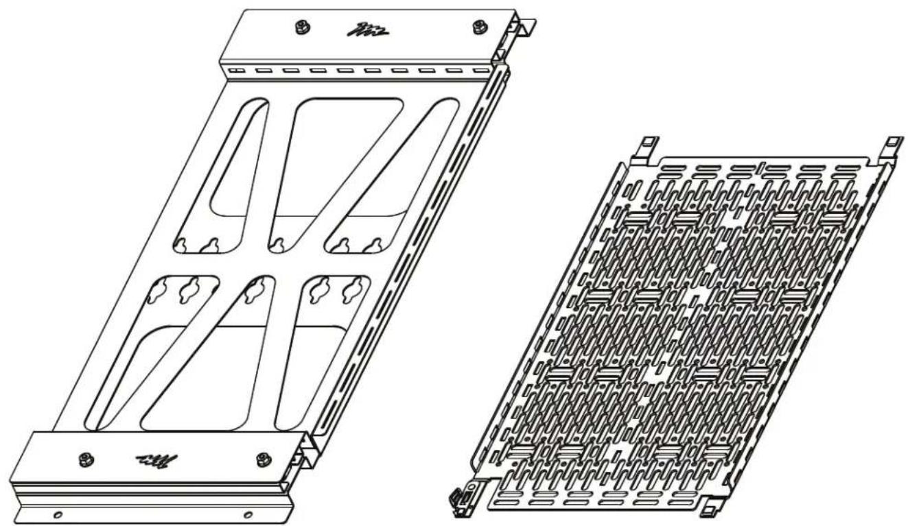
Sliding Mounting Plate A
Lever LockTM B

(2x) Rivet C

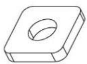
(2x) Washer D
(4x) Binding Head Screw E
(4x) Square Nut F
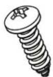
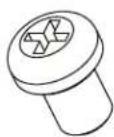
(4x) Pan Head Screw G
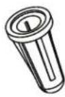
(4x) Drywall Anchor H

(20x) Washer J
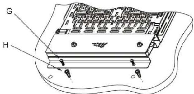
INSTALLING THE SLIDING MOUNTING PLATE TO THE WALL
NOTE: Sliding mounting plate (A) may be installed directly on the wall in 2 horizontal positions as shown.
- Using (4x) pan head screws (G) and (4x) drywall anchors (H) provided, mount the sliding plate to the wall as shown. (FIGURE A)

CAUTION: Only drywall anchors (H) are to be used for mounting to 3/8 minimum to 5/8 maximum thick drywall.

CAUTION: Lever Lock must be mounted with the clip at the bottom.

Horizontal Wall Mount - Left
FIGURE A
INSTALLING THE SLIDING MOUNTING PLATE TO THE FRONT OF AN EXTRAUSION
- Remove screws and endcap to access binding head screws (E) and square nuts (F).
- Pre-load (4x) binding head screws (E) and (4x) square nuts (F) loose prior to mounting the sliding plate providing clearance for mounting. (FIGURE B)
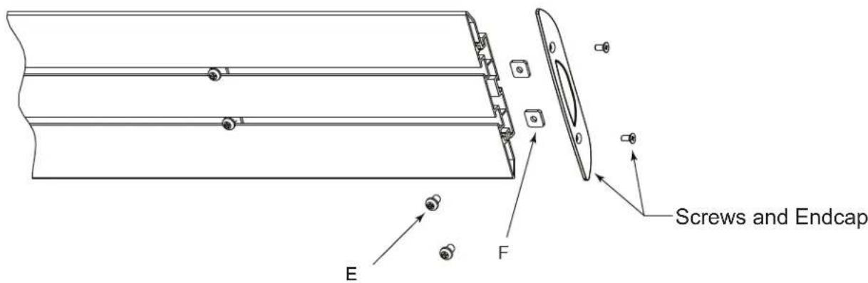
FIGURE B
- Mount sliding plate (A) over screws (E) utilizing keyholes in plate by lowering sliding plate until it rests on screws. (FIGURE C)
- Tighten screws securely against plate.
NOTE: At a minimum use 2 pairs of mounting keyholes to safely mount the sliding plate to the extrusion as far apart as possible.
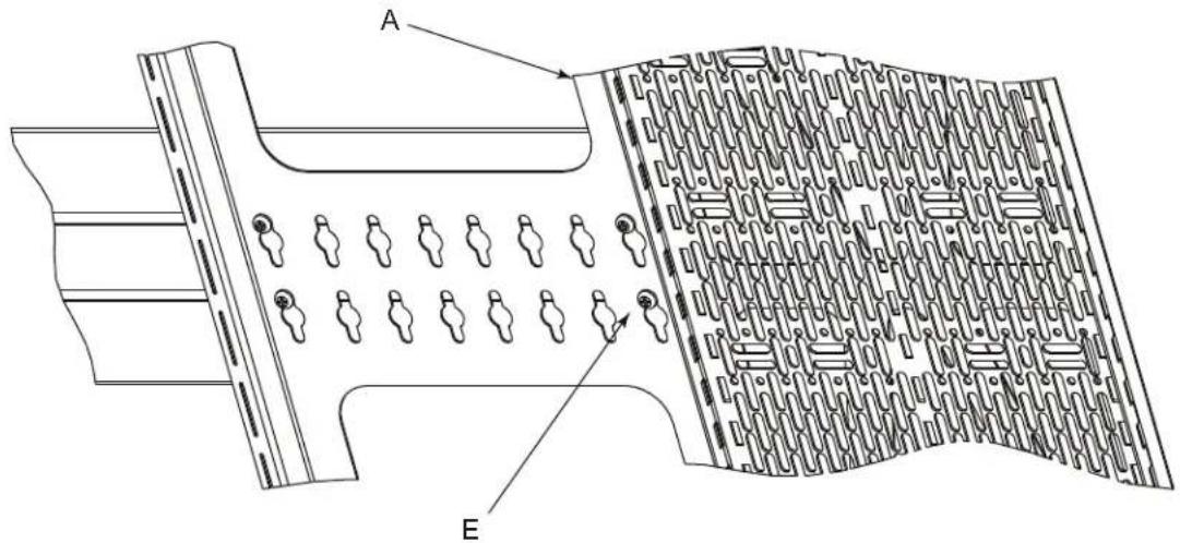
FIGURE C
INSTALLING THE SLIDING MOUNTING PLATE TO THE FRONT OF AN EXTRUSION CONT'D
NOTE: Sliding mounting plate can be place to either the extreme right end of the extrusion, or the extreme left end of the extrusion. (FIGURE D)


CAUTION: Lever Lock must be mounted with the clip at the bottom.

- Remove screws and endcap to access binding head screws (E) and square nuts (F).
- Pre-load (2x) binding head screws (E), (2x) washers (D) and (2x) square nuts (F) loose prior to mounting the sliding plate providing clearance for mounting. (FIGURE E)
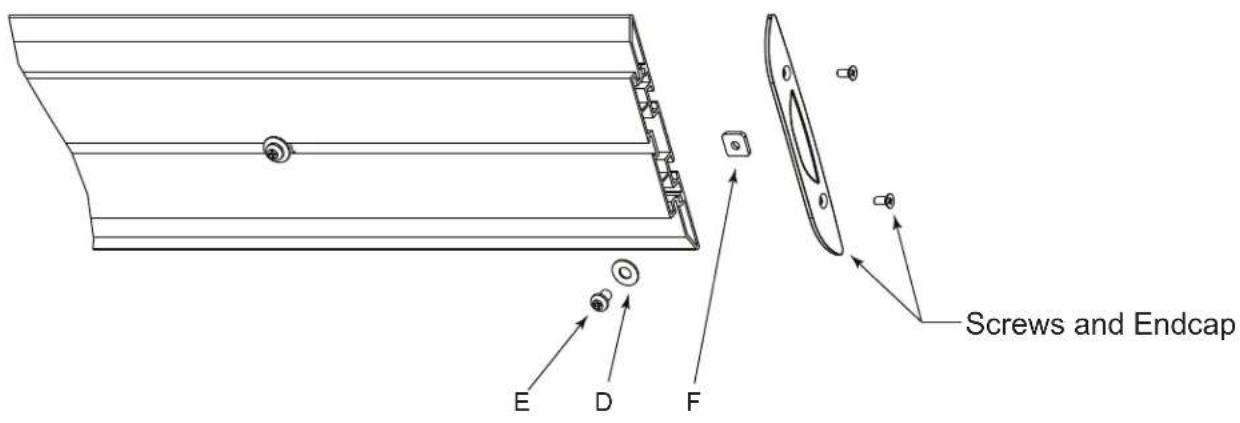
FIGURE E
- Mount sliding plate (A) over screws (E) utilizing keyholes in plate by lowering sliding plate until it rests on screws. (FIGURE F)
- Tighten screws/washers securely against plate.
NOTE: At a minimum use 2 mounting keyholes to safely mount the sliding plate to the extrusion as far apart as possible.
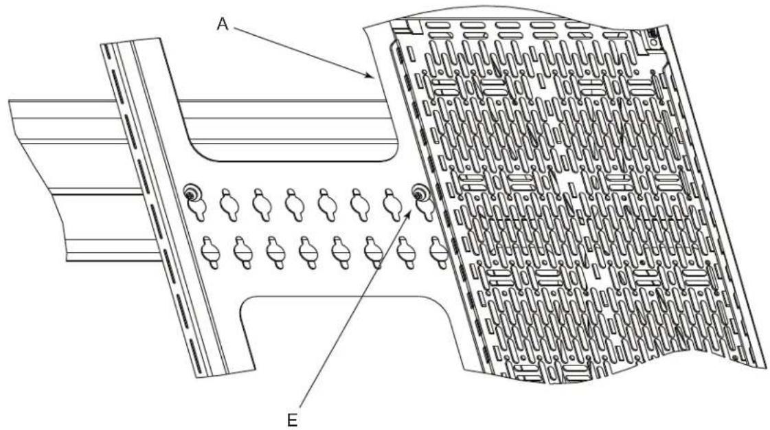
FIGURE F
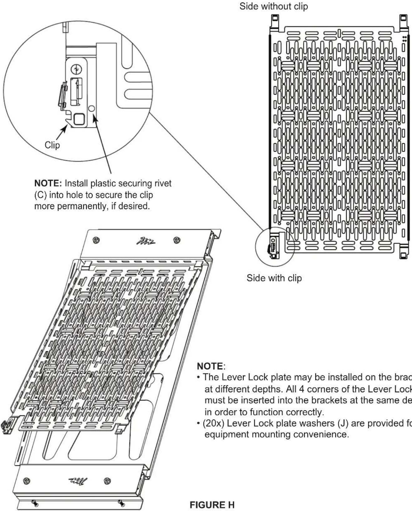
INSTALLING THE SLIDING MOUNTING PLATE TO THE BACK OF AN EXTRAUSION CONT'D
NOTE: Sliding mounting plate can be place to either the extreme right end of the extrusion, or the extreme left end of the extrusion. (FIGURE G)
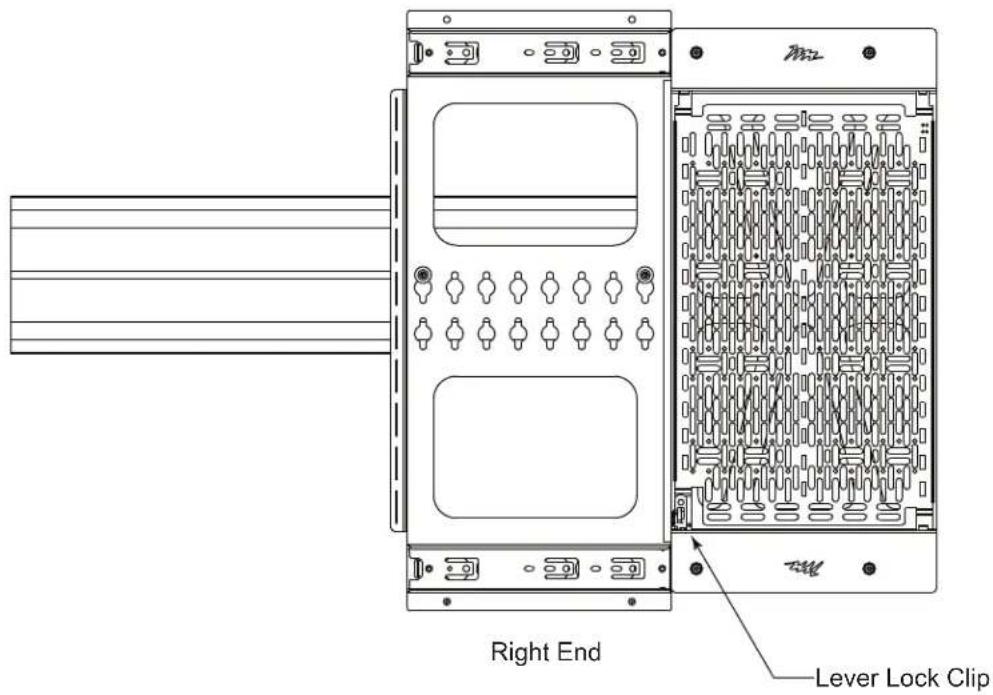

CAUTION: Lever Lock must be mounted with the clip at the bottom.

- Attach the Lever Lock plate (B) by installing the side without the clip into the bracket first.
- Install the side with the clip until it clicks into place. (FIGURE H)
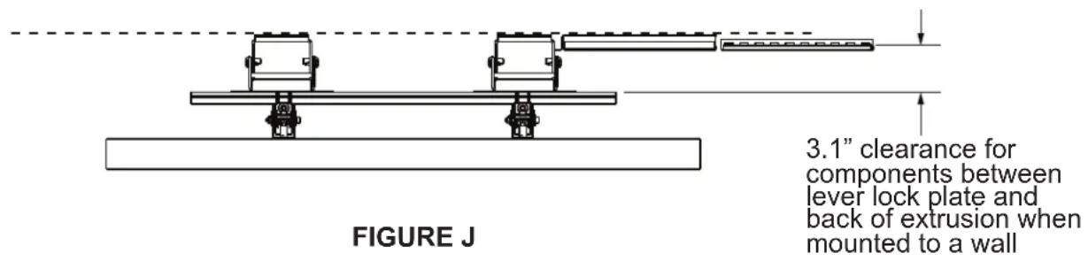
Method 1 - Attach the sliding mounting plate (A) directly to the wall. (FIGURE J)
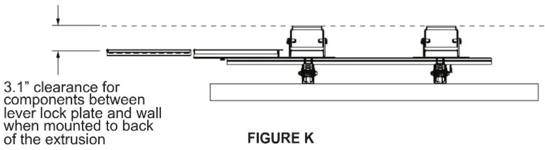
Method 2 - Attach the sliding mounting plate (A) to the back of the extrusion. (FIGURE K)
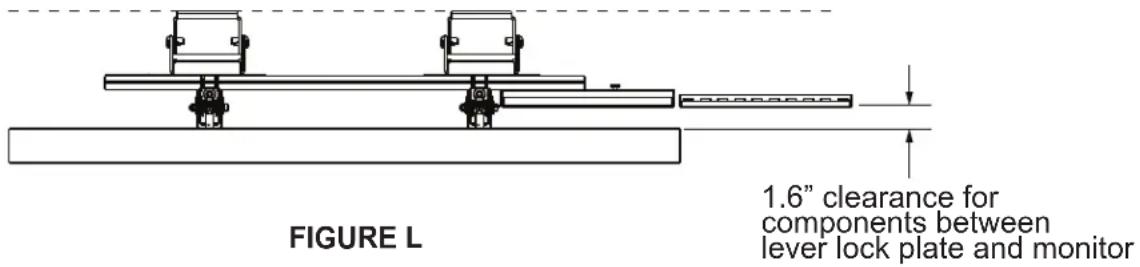
Method 3 - Attach the sliding mounting plate (A) to the front of the extrusion. (FIGURE L)
WARRANTY
For warranty information, refer to http://www.middleatlantic.com/company/about-us.aspx#warranty
Corporate Headquarters
Corporate Voice: 973-839-1011 - Fax: 973-839-1976 / International Voice: +1 973-839-8821 -
Middle Atlantic Canada
Voice: 613-836-2501 - Fax: 613-836-2690 / ca.middleatlantic.com -
customerservicecanada@midgeatlantic.ca
Factory Distribution
USA: NJ - CA - IL Canada: ON - BC
At Middle Atlantic Products we are always listening. Your comments are welcome.
Middle Atlantic Products is an ISO 9001 and ISO 14001 Registered Company.

Middle Atlantic Products
what great systems are built on™
middleatlantic.com 800.266.7225

- PRODUCT FEATURES
- IMPORTANT SAFETY INSTRUCTIONS
- INSTRUCTIONS IMPORTANTES SUR LA SECURITE
- INSTALLING THE SLIDING MOUNTING PLATE TO THE WALL
- INSTALLING THE SLIDING MOUNTING PLATE TO THE FRONT OF AN EXTRAUSION
- INSTALLING THE SLIDING MOUNTING PLATE TO THE FRONT OF AN EXTRUSION CONT'D
- INSTALLING THE SLIDING MOUNTING PLATE TO THE BACK OF AN EXTRAUSION CONT'D
- WARRANTY
- Corporate Headquarters
- Middle Atlantic Canada
- Factory Distribution
- Middle Atlantic Products
Brand : Middle Atlantic
Model : PRX-SMP-15X10
Category : Mounting bracket