RXC50AV1B - Fridge DAIKIN - Free user manual and instructions
Find the device manual for free RXC50AV1B DAIKIN in PDF.

| Product Type | Split air conditioner (outdoor unit) |
| Brand | Daikin |
| Model | RXC50AV1B |
| Category | Air conditioner |
| Refrigerant | R32 (GWP = 675) |
| Dimensions (W x H x D) | 855 x 628 x 328 mm |
| Power supply | 220-240 V ~ 50 Hz |
| Power cable cross-section | 2.5 mm² (3 conductors) |
| Connection cable cross-section | 2.5 mm² (4 conductors) |
| Recommended fuse/circuit breaker | 20 A |
| Maximum pipe length | 30 m |
| Maximum allowable height difference | 15 m |
| Factory refrigerant charge (for 7.5 m) | 1.1 kg |
| Additional charge per meter beyond 7.5 m | 17 g/m |
| Filters | Washable air filter (every 2 weeks) + optional Bio filter |
| Main functions | Cooling, heating (heat pump), automatic mode, timer, sleep mode |
| Protections | Compressor protection (3-minute delayed start), automatic defrost |
| Cleaning and maintenance | Clean the air filter every 2 weeks with warm water (< 40 °C); clean the panel with a soft cloth |
| Installation conditions | Max altitude 2000 m; avoid heat sources and flammable gases; respect minimum clearance distances (300 mm) |
Frequently Asked Questions - RXC50AV1B DAIKIN
User questions about RXC50AV1B DAIKIN
0 question about this device. Answer the ones you know or ask your own.
Ask a new question about this device
Download the instructions for your Fridge in PDF format for free! Find your manual RXC50AV1B - DAIKIN and take your electronic device back in hand. On this page are published all the documents necessary for the use of your device. RXC50AV1B by DAIKIN.
USER MANUAL RXC50AV1B DAIKIN
INSTALLATION AND MAINTENANCE MANUAL
R32 SPLIT SERIES

MODELS
FTXC25AV1B RXC25AV1B
FTXC35AV1B RXC35AV1B
FTXC50AV1B RXC50AV1B
FTXC60AV1B RXC60AV1B
Installation Manual R32 Split Series
OUTLINE AND DIMENSIONS
Indoor Unit [FTXC]
THE MARK (SHOWS)PIPING DIRECTION
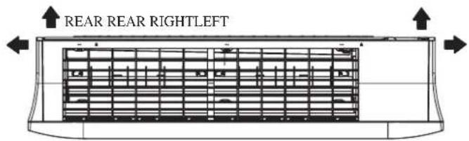
TOP VIEW
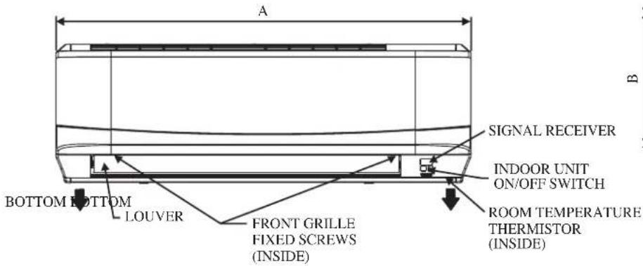
FRONT VIEW
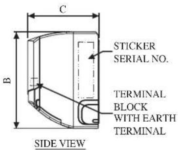
Indoor Unit [FTXC]
| DimensionModel | A | B | C | D | E | F | G | H | I | J | K | L | M | |
| 25/35 859 288 209 104 | 141 30 | 46 55 | 56 153 | 181 207 | 52 |
Indoor Unit [FTXC]
| DimensionModel | A | B | C | D | E | F | G | H | I | J | K | L | M | |
| 50/60 1124 310 237 19 | 0 173 61 | 40 45 | 48 91 2 | 19 580 | 45 |
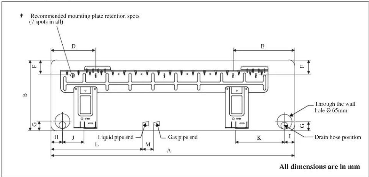
Outdoor Unit [RXC]
![DAIKIN RXC50AV1B - Outdoor Unit [RXC] - 1](/content/2026/04/669707/images/8203b57f86e5feb4e8a96dd541285a5425b4da26d9361702e43cc6457574a249.jpg)
All dimensions are in mm
| Model\Dimension | A | B | C | D | E | F | G | H | I | J | K | L | M | N | O | P | Q | |
| 25/35 550 658 51 11 27 | 3 16 | 14 470 | 96 93 | 94 60 | 14 | 133 8 | 10 299 |
Outdoor Unit [RXC]
![DAIKIN RXC50AV1B - Outdoor Unit [RXC] - 1](/content/2026/04/669707/images/9fa0fc8f879d63a0dbdcc742b52ddc6b936b118119c84abdcc7fd29ccf4968a2.jpg)
All dimensions are in mm
| Model\Dimension | A | B | C | D | E | F | G | H | I | J | K | L | M | N | O | |
| 50 | 855 | 628 | 328 | 520 | 179 | 46 | 93 | 149 | 101 | 113 | 603 | 126 | 164 | 15 | 34 | |
| 60 | 855 | 730 | 328 | 520 | 179 | 46 | 93 | 149 | 101 | 113 | 603 | 126 | 164 | 15 | 34 |
| Model\Dimension | P | Q | R | S | T | U | V |
| 50 | 23 | 362 | 73 | 75 | 8 | 67 | 7 |
| 60 | 23 | 362 | 73 | 75 | 8 | 67 | 7 |
INSTALLATION MANUAL
This manual provides the procedures of installation to ensure a safe and good standard of operation for the air conditioner unit.
Special adjustment may be necessary to suit local requirement.
Before using your air conditioner, please read this instruction manual carefully and keep it for future reference.
This appliance is intended to be used by expert or trained users in shops, in light industry and on farms, or for commercial use by lay persons.
This appliance is not intended for use by persons, including children, with reduced physical, sensory or mental capabilities, or lack of experience and knowledge, unless they have been given supervision or instruction concerning use of the appliance by a person responsible for their safety.
Children should be supervised to ensure that they do not play with the appliance.
SAFETY PRECAUTIONS
⚠ WARNING ⚠ CAUTION
- Installation and maintenance should be performed by qualified persons who are familiar with local code and regulation, and experienced with this type of appliance.
- All field wiring must be installed in accordance with the national wiring regulation.
- Ensure that the rated voltage of the unit corresponds to that of the name plate before commencing wiring work according to the wiring diagram.
- The unit must be GROUNDED to prevent possible hazard due to insulation failure.
- All electrical wiring must not touch the water piping or any moving parts of the fan motors.
- Confirm that the unit has been switched OFF before installing or servicing the unit.
- Disconnect from the main power supply before servicing the air conditioner unit.
- DO NOT pull out the power cord when the power is ON. This may cause serious electrical shocks which may result in the fire hazards.
- Keep the indoor and outdoor units, power cable and transmission wiring, at least 1m from TVs and radios, to prevent distorted pictures and static. {Depending on the type and source of the electrical waves, static may be heard even when more than 1m away}.
WARNING
Do not use means to accelerate the defrosting process (if applicable) or to clean, other than those recommended by the manufacturer. The appliance shall be stored in a room without continuously operating ignition sources (for example: open flames, an operating gas appliance or an operating electric heater). Do not pierce or burn. Be aware that refrigerants may not contain an odour. Appliance shall be installed, operated and stored in a room with a floor area larger than Xm^2 (refer to page 13).
NOTE: The manufacturer may provide other suitable examples or may provide additional information about the refrigerant odour.
Please take note of the following important points when installing.
- Do not install the unit where leakage of flammable gas may occur.
If gas leaks and accumulates around the unit, it may cause fire ignition.
- Ensure that drainage piping is connected properly.
If the drainage piping is not connected properly, it may cause water leakage which will dampen the furniture.
- Do not overcharge the unit.
This unit is factory pre-charged. Overcharge will cause over-current or damage to the compressor.
- Ensure that the unit's panel is closed after service or installation.
Unsecured panels will cause the unit to operate noisily.
- Sharp edges and coil surfaces are potential locations which may cause injury hazards. Avoid from being in contact with these places.
- Before turning off the power supply set the remote controller's ON/OFF switch to the "OFF" position to prevent the nuisance tripping of the unit. If this is not done, the unit's fans will start turning automatically when power resumes, posing a hazard to service personnel or the user.
- Do not install the units at or near doorway.
- Do not operate any heating apparatus too close to the air conditioner unit or use in room where mineral oil, oil vapour or oil steam exist, this may cause plastic part to melt or deform as a result of excessive heat or chemical reaction.
- When the unit is used in kitchen, keep flour away from going into suction of the unit.
- This unit is not suitable for factory used where cutting oil mist or iron powder exist or voltage fluctuates greatly.
- Do not install the units at area like hot spring or oil refinery plant where sulphide gas exists.
- Ensure the color of wires of the outdoor unit and the terminal markings are same to the indoors respectively.
- IMPORTANT : DO NOT INSTALL OR USE THE AIR CONDITIONER UNIT IN A LAUNDRY ROOM.
- Do not use joined and twisted wires for incoming power supply.
- The equipment is not intended for use in a potentially explosive atmosphere.
NOTICE
Disposal requirements
Your air conditioning product is marked with this symbol. This means that electrical and electronic products shall not be mixed with unsorted household waste.
Do not try to dismantle the system yourself: the dismantling of the air conditioning system, treatment of the refrigerant, of oil and of other parts must be done by a qualified installer in accordance with relevant local and national legislation.
Air conditioners must be treated at a specialized treatment facility for re-use, recycling and recovery. By ensuring this product is disposed of correctly, you will help to prevent potential negative consequences for the environment and human health. Please contact the installer or local authority for more information.
Batteries must be removed from the remote controller and disposed of separately in accordance with relevant local and national legislation.
IMPORTANT
Important information regarding the refrigerant used
This product contains fluorinated greenhouse gases.
Do not vent gases into the atmosphere.
Refrigerant type: R32
GWP ^(1) value: 675
(1) GWP = Global Warming Potential
1 Please fill in with indelible ink,
■ ① the factory refrigerant charge of the product,
■ ② the additional refrigerant amount charged in the field and
■ ① + ② the total refrigerant charge
on the refrigerant charge label supplied with the product.
The filled out label must be adhered in the proximity of the product charging port (e.g. onto the inside of the service cover).
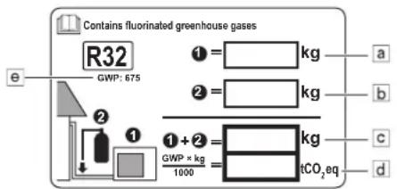
a Factory refrigerant charge: see unit name plate
b Additional refrigerant amount charged
c Total refrigerant charge
d Greenhouse gas emissions of the total refrigerant charge expressed as tonnes CO_2 -equivalent
e GWP = Global warming potential

NOTICE
In Europe, the greenhouse gas emissions of the total refrigerant charge in the system (expressed as tonnes CO_2 -equivalent) is used to determine the maintenance intervals. Follow the applicable legislation.
Formula to calculate the greenhouse gas emissions:
GWP value of the refrigerant × Total refrigerant charge [in kg] / 1000
Fix the label on the inside of the outdoor unit. There is a dedicated place for it on the wiring diagram label.2
INSTALLATION DIAGRAM
INSTALLATION OF THE OUTDOOR UNIT (25/35)
- Where a wall or other obstacle is in the path of outdoor unit's intake or exhaust airflow, follow the installation guidelines below.
- For any of the below installation patterns, the wall height on the exhaust side should be 1200mm or less.
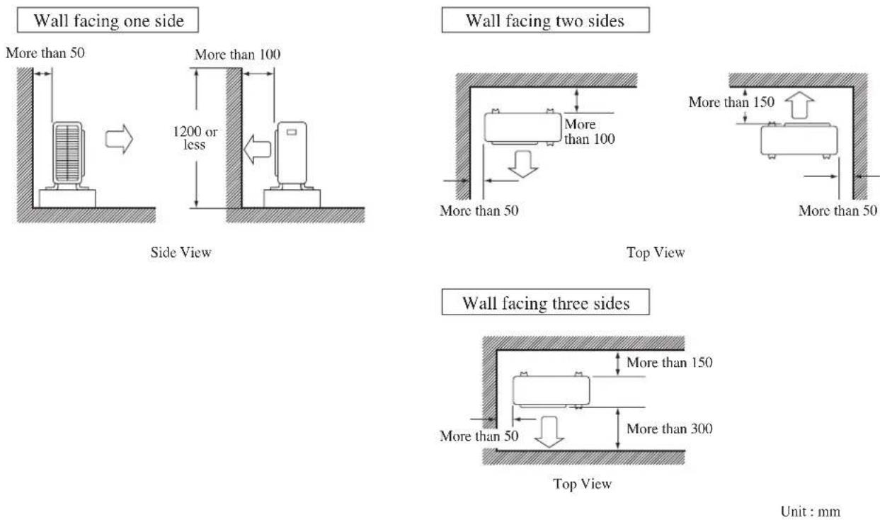
Unit : mm
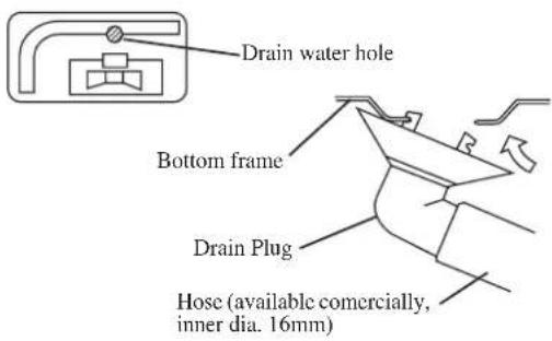
Drain work. (Heat Pump Unit Only)
1) Use drain plug for drainage.
2) If the drain port is covered by a mounting base or floor surface, place additional foot bases of at least 30mm in height under the outdoor unit's feet.
3) In cold areas, do not use a drain hose with the outdoor unit. (Otherwise, drain water may freeze, impairing heating performance.)
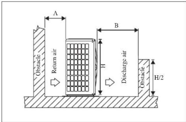
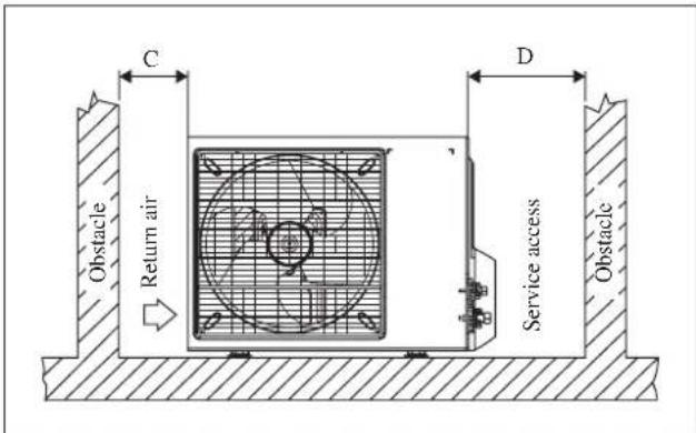
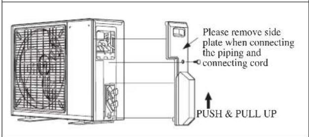
INSTALLATION OF THE OUTDOOR UNIT (50/60)
The outdoor unit must be installed in such a way, so as to prevent short circuit of the hot discharged air or obstruction to the smooth air flow. Please follow the installation clearances shown in the figure. Select the coolest possible place where intake air temperature is not greater than the outside air temperature (Refer to operating range).
Installation clearances
| Dimension | A | B | C | D |
| Minimum Distance, mm | 300 1000 | 300 500 |
Note: If there is any obstacle higher than half, of the unit's height (H), please allow more space than the figure indicated in the above table.
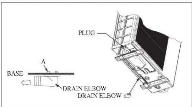
Condensed Water Disposal Of Outdoor Unit (Heat Pump Unit Only)
- There are 2 holes on the base of Outdoor Unit for condensed water to flow out. Insert the drain elbow to one of the holes.
- To install the drain elbow, first insert one portion of the hook to the base (portion A), then pull the drain elbow in the direction shown by the arrow while inserting the other portion to the base. After installation, check to ensure that the drain elbow clings to base firmly.
- If the unit is installed in a snowy and chilly area, condensed water may freeze in the base. In such case, please remove plug at the bottom of unit to smooth the drainage.
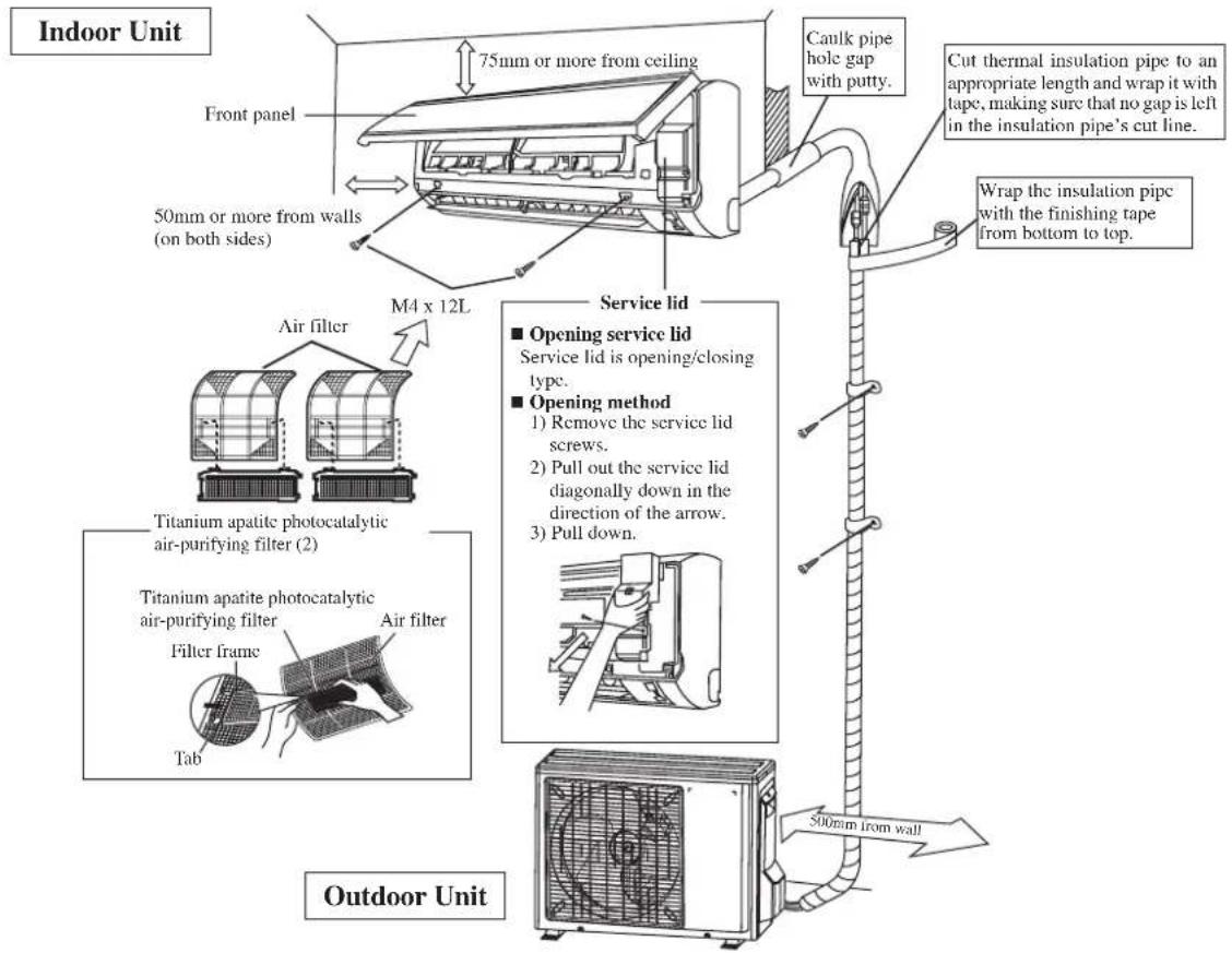
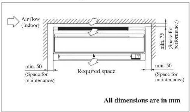
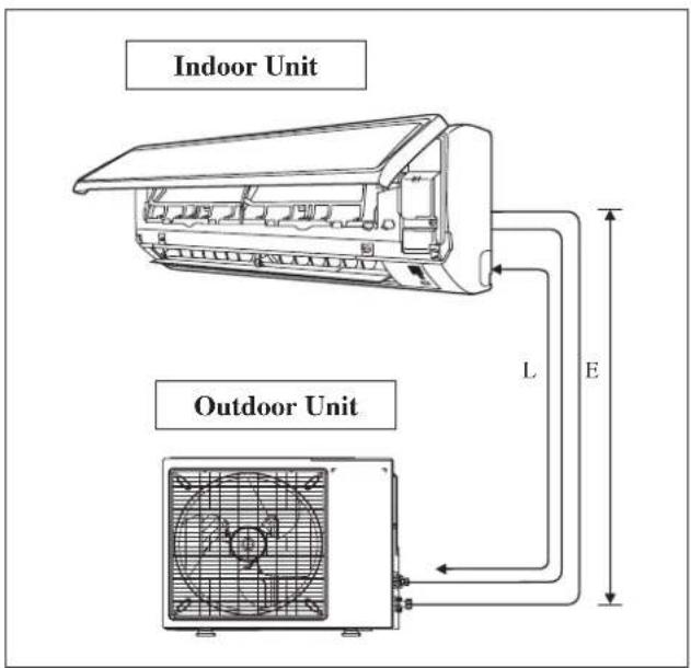
INSTALLATION OF THE INDOOR UNIT
The indoor unit must be installed in such a way so as to prevent short circuit of the cool discharged air with the hot return air. Please follow the installation clearance shown in the figure. Do not place the indoor unit where there could be direct sunlight shining on it. Also, this location must be suitable for piping and drainage, and be away from doors or windows.
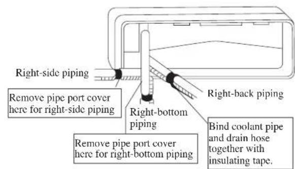
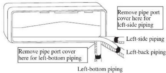
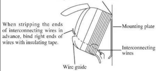
The refrigerant piping can be routed to the unit in a number of ways (left or right from the back of the unit), by using the cut-out holes on the casing of the unit. Bend the pipes carefully to the required position in order to align it with the holes. For the side and bottom out, hold the bottom of the piping and then position it to the required direction. The condensation drain hose can be taped to the pipes.
Right-side, right-back or right-bottom piping
Left-side, left-back or left-bottom piping
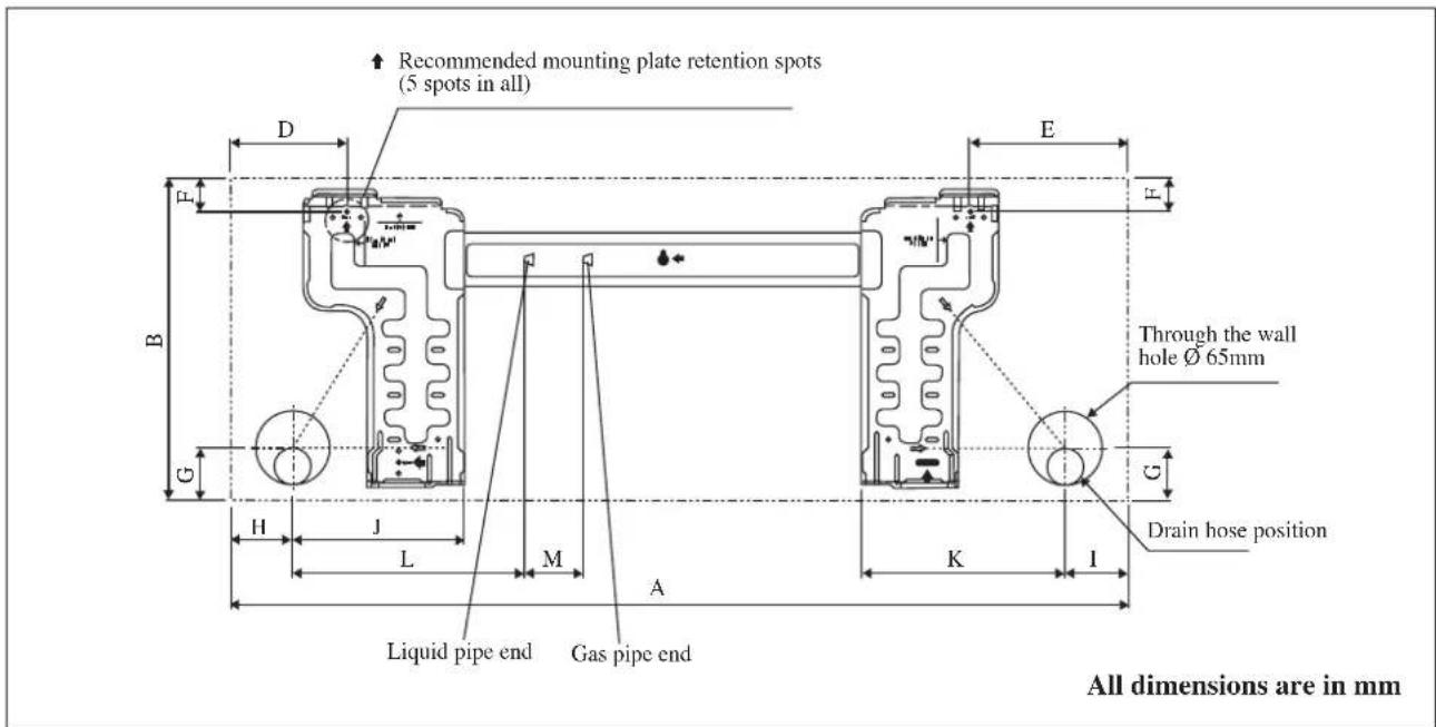
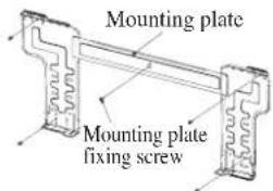
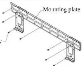
Mounting Installation Plate
Ensure that the wall is strong enough to withstand the weight of the unit. Otherwise, it is necessary to reinforce the wall with plates, beams or pillars.
Use the level gauge for horizontal mounting, and fix it with 5 suitable screws for FTXC 25/35 and 7 suitable screws for FTXC 50/60.
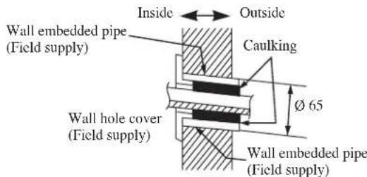
In case the rear piping draws out, drill a hole 65mm in diameter with a cone drill, slightly lower on the outside wall (see figure).
FTXC 25/35
FTXC 50/60
Mounting plate fixing screw
Recommended Mounting Plate Retention Spots And Dimensions
FTXC 25/35

FTXC 50/60
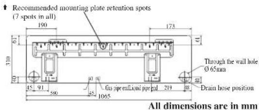
Hole with cone drill
Mount The Unit Onto The Installation Plate
Hook the indoor unit onto the upper portion of the installation plate (Engage the two hooks at the rear top of the indoor unit with the upper edge of the installation plate). Ensure that the hooks are properly seated on the installation plate by moving it to the left and right.
How To Attach The Indoor Unit
Hook the claws of the bottom frame to the mounting plate.
How To Remove The Indoor Unit
Push up the marked area (at the lower part of the front grille) to release the claws.
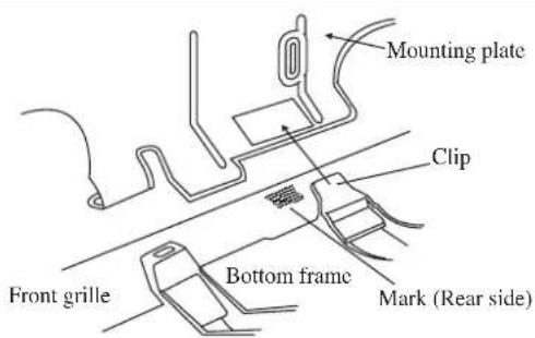
Hang indoor unit's hook here.
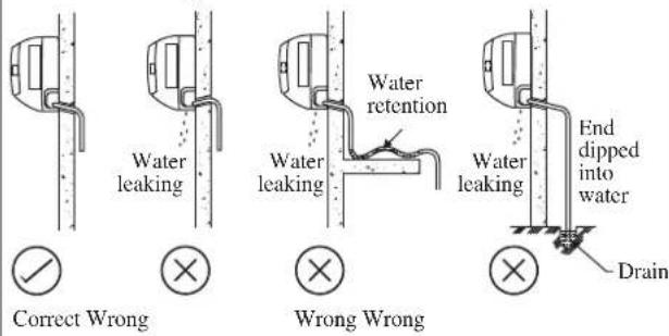
Water Drainage Piping
The indoor drain pipe must be in a downward gradient for smooth drainage. Avoid situations that are likely to cause water to leak.
Water Drainage

CAUTION
- Do not install the unit at altitude over 2000m for both indoor & outdoor.
REFRIGERANT PIPING
Allowable Piping Length
If the pipe is too long, both the capacity and reliability of the unit will drop. As the number of bends increases, resistance to the flow of refrigerant system increases, thus lowering cooling capacity. As a result, the compressor may become defective. Always choose the shortest path and follow the recommendations as tabulated below:
| Model | Indoor (FTXC) | 25 | 35 | 50 | 60 | ||
| Outdoor (RXC) | 25 | 35 | 50 | 60 | |||
| Min. Allowable Length (L), m 3 | 3 | ||||||
| Max. Allowable Length (L), m 20 30 | |||||||
| Max. Allowable Elevation (E), m 15 15 | |||||||
| Gas Pipe Size, mm/(in) | 9.52 (3/8") 12.70 (1/2") | ||||||
| Liquid Pipe Size, mm/(in) | 6.35 (1/4") 6.35 (1/4") | ||||||
*Be sure to add the proper amount of additional refrigerant. Failure to do so may result in reduced performance.
Remark: The refrigerant pre-charged in the outdoor unit is for piping length up to 7.5m.
Equivalent length for various fitting (meter)
| Pipe Size L joint Trap bend |  |  |
| 3/8" (OD9.52mm) 0.18 1.3 | ||
| 1/2" (OD12.7mm) 0.20 1.5 | ||
| 5/8" (OD15.9mm) 0.25 2.0 | ||
| 3/4" (OD19.1mm) 0.35 2.4 | ||
| 7/8" (OD22.2mm) 0.40 3.0 | ||
| 1" (OD25.4mm) 0.45 3.4 | ||
| 1 1/8" (OD28.6mm) 0.50 3.7 | ||
| 1 3/8" (OD34.9mm) 0.60 4.4 |
Notes:
1. Equivalent piping length is obtained with actual length of gas piping.
2. 90° bend of piping is equivalent to L joint.
Bending must be carefully made so as not to crush the pipe. Use a pipe bender to bend a pipe where possible.
REFRIGERANT PIPING
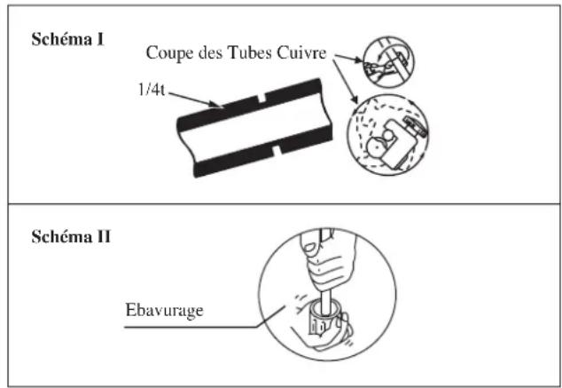
Piping Works And Flaring Technique
- Do not use contaminated or damaged copper tubing. If any piping, evaporator or condenser had been exposed or had been opened for 15 seconds or more, the system must be vacuumed. Generally do not remove plastic, rubber plugs and brass nuts from the valves, fittings, tubing and coils until it is ready to connect suction or liquid line into valves or fittings.
- If any brazing work is required, ensure that nitrogen gas is passed through coil and joints while the brazing work is being done. This will eliminate soot formation on the inside wall of copper tubings.
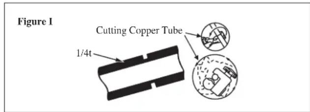
- Cut the pipe stages by stages, advancing the blade of pipe cutter slowly. Extra force and a deep cut will cause more distortion of pipe and therefore extra burr. See Figure I.
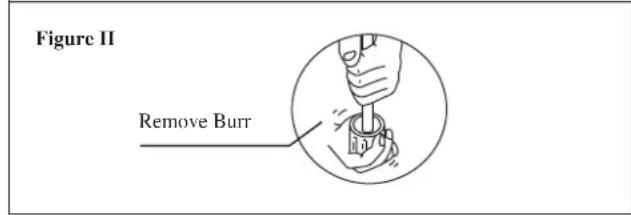
- Remove burrs from cut edges of the pipes with remover. See Figure II. Hold the pipe on top position and burr remover at lower position to prevent metal chips from entering the pipe. This will avoid unevenness on the flare faces which will cause gas leak.
- Insert the flare nuts, mounted on the connection parts of both the indoor unit and outdoor unit, into the copper pipes.
- The exact length of pipe protruding from the top surface of the swaging block is determined by the flaring tool. See Figure III.
- Fix the pipe firmly on the swaging block. Match the centers of both the swaging block and the flaring punch, then tighten the flaring punch fully.
- The refrigerant pipe connection are insulated by closed cell polyurethane.
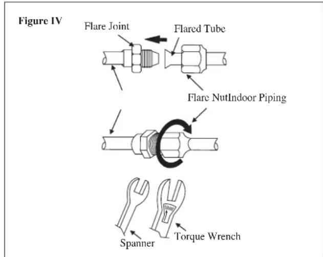
Piping Connection To The Units
- Align the center of the piping and tighten the flare nut sufficiently with fingers. See Figure IV.
- Finally, tighten the flare nut with torque wrench until the wrench clicks.
- When tightening the flare nut with the torque wrench, ensure that the tightening direction follows the arrow indicated on the wrench.
- The refrigerant pipe connection are insulated by closed cell polyurethane.
| Pipe Size, mm (in) Torque, Nm/(ft-lb) | |
| 6.35 (1/4") 18 (13.3) | |
| 9.52 (3/8") 42 (31.0) | |
| 12.70 (1/2") 55 (40.6) | |
| 15.88 (5/8") 65 (48.0) | |
| 19.05 (3/4") 78 (57.6) | |
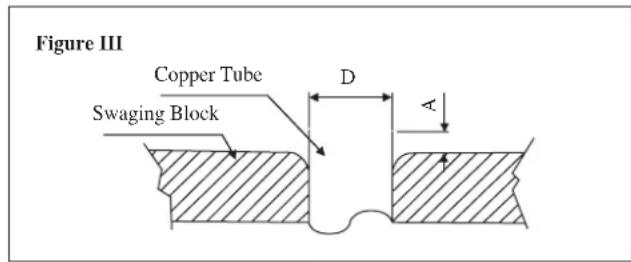
| ∅ Tube, D A (mm) | ||
| Inch mm Imperial(Wing-nut Type) | Rigid(Clutch Type) | |
| 1/4" 6.35 1.3 0.7 | ||
| 3/8" 9.52 1.6 1.0 | ||
| 1/2" 12.70 1.9 1.3 | ||
| 5/8" 15.88 2.2 1.7 | ||
| 3/4" 19.05 2.5 2.0 | ||
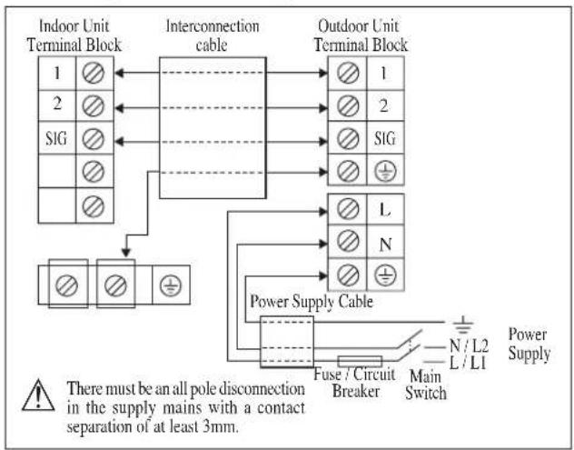
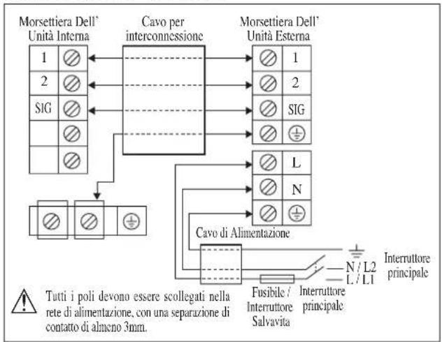
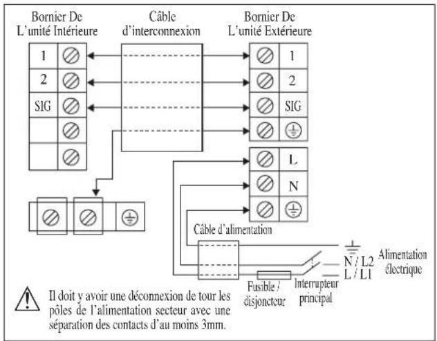
ELECTRICAL WIRING CONNECTION
IMPORTANT: * The figures shown in the table are for information purpose only. They should be checked and selected to comply with the local/national codes of regulations. This is also subject to the type of installation and conductors used.
** The appropriate voltage range should be checked with label data on the unit.
Inverter (Power Outdoor)
flowchart
graph TD
    A["Indoor Unit Terminal Block"] --> B["Interconnection cable"]
    C["Outdoor Unit Terminal Block"] --> B
    B --> D["Power Supply Cable"]
    D --> E["Fuse / Circuit Breaker"]
    E --> F["Main Switch"]
    F --> G["Power Supply"]
    style A fill:#f9f,stroke:#333
    style C fill:#f9f,stroke:#333
    style B fill:#ccf,stroke:#333
    style D fill:#cfc,stroke:#333
    style E fill:#fcc,stroke:#333
    style F fill:#cff,stroke:#333
    note1["There must be an all pole disconnection in the supply mains with a contact separation of at least 3mm."] --> A
    note2["SIG"] --> A
    note3["L"] --> D
    note4["N"] --> D
    note5["⊕"] --> B
    note6["L"] --> D
    note7["⊕"] --> B
| Model | Indoor(FTXC) | 25 35 50 60 | |||
| Outdoor(RXC) | 25 35 50 60 | ||||
| Voltage range** | 220-240V~/50Hz + ⊕ | ||||
| Power supply cable size* mm2Number of conductors | 1.5 | 2.5 | |||
| 3 | 3 | ||||
| Interconnection cable size* mm2Number of conductors | 1.5 | 2.5 | |||
| 4 | 4 | ||||
| Recommended fuse /circuit breaker rating A 16/20 | |||||
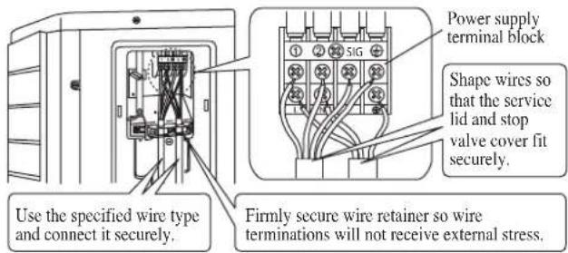
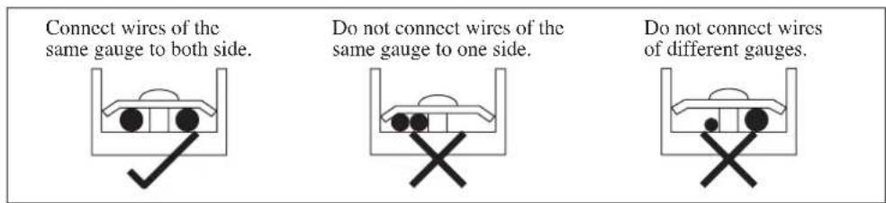
- All wires must be firmly connected.
- Make sure all the wire do not touch the refrigerant pipings, compressor or any moving parts.
- The connecting wire between the indoor unit and the outdoor unit must be clamped by using provided cord anchorage.
- The power supply cord must be equivalent to H07RN-F which is the minimum requirement.
- Make sure no external pressure is applied to the terminal connectors and wires.
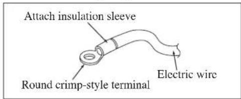
• Make sure all the covers are properly fixed to avoid any gap. - Use round crimp-style terminal for connecting wires to the power supply terminal block. Connect the wires by matching to the indication on terminal block. (Refer to the wiring diagram attached on the unit).
• Used the correct screwdriver for terminal screws tightening. Unsuitable screwdrivers can damage the screw head.
• Over tightening can damage the terminal screws.
- Do not connect wire of different gauge to same terminal.
- Keep wiring in an orderly manner. Prevent the wiring from obstructing other parts and the terminal box cover.
SPECIAL PRECAUTIONS WHEN DEALING WITH R32 UNIT
| Model | R32 charge, kg for 7.5m piping | Minimum floor area, Xm^2 (based on 7.5m piping) | R32 charge, kg for max allowable pipe length* | Minimum floor area, Xm^2 (based on max allowable pipe length *) |
| FTXC25AV1B - RXC25AV1B 0.6 | 0.34 0.94 0.84 | |||
| FTXC35AV1B - RXC35AV1B 0.8 | 0.61 1.14 1.24 | |||
| FTXC50AV1B - RXC50AV1B 1.1 | 1.15 1.61 2.47 | |||
| FTXC60AV1B - RXC60AV1B 1.2 | 1.37 1.71 2.79 |
Installation Height, h_n (m) = 1.8
*Max. Allowable Length (L), m for:-
FTXC25/35A-RXC25/35A : 20
FTXC50/60A-RXC50/60A : 30
- Installation of pipe work shall be kept to a minimum and pipe work shall be protected from physical damage and shall not be installed in an unventilated space;
- Reusable mechanical connectors and flare joints shall be accessible for maintenance purposes;
WARNING
Prior to installation, ensure risk of ignition is minimised and avoid working in confined space. Ensure adequate ventilation is available by opening windows or doors.
- When flared joints are reused indoors, the flare part shall be re-fabricated.
- Avoid installation of the air conditioner in a place where there is danger of exposure to continuously operating open flames (for example an operating electric heaters).
- Any person who is involved with working on or breaking into a refrigerant circuit should hold a current valid certificate from an industry-accredited assessment authority, which authorises their competence to handle refrigerants safely in accordance with an industry recognised assessment specification.
- Checking for presence of refrigerant
The area shall be checked with an appropriate refrigerant detector prior to and during work, to ensure the technician is aware of potentially flammable atmospheres. Ensure that the leak detection equipment being used is suitable for use with flammable refrigerants, i.e. nonsparking, adequately sealed or intrinsically safe.
• Presence of fire extinguisher
If any hot work is to be conducted on the refrigeration equipment or any associated parts, appropriate fire extinguishing equipment shall be available to hand. Have a dry powder or CO_2 fire extinguisher adjacent to the charging area.
- No ignition sources
All possible ignition sources, including cigarette smoking, should be kept sufficiently far away from the site of installation, repairing, removing and disposal, during which flammable refrigerant can possibly be released to the surrounding space. "No Smoking" signs shall be displayed.
- The following checks shall be applied to installations:
– marking to the equipment continues to be visible and legible. Markings and signs that are illegible shall be corrected;
- refrigeration pipe or components are installed in a position where they are unlikely to be exposed to any substance which may corrode refrigerant containing components, unless the components are constructed of materials which are inherently resistant to being corroded or are suitably protected against being so corroded.
- Initial safety checks shall include:
– that capacitors are discharged, this shall be done in a safe manner to avoid possibility of sparking
– there shall be no live electrical components and wiring are exposed while charging, recovering or purging the system;
• Repair to intrinsically safe components
Do not apply any permanent inductive or capacitance loads to the circuit without ensuring that this will not exceed the permissible voltage and current permitted for the equipment in use.
Replace components only with parts specified by the manufacturer.
- Leak detection methods
Ensure that the detector is not a potential source of ignition (for example a halide torch) and is suitable for the refrigerant used. Leak detection equipment shall be set at a percentage of the LFL of the refrigerant (for R32, LFL is 13%) and shall be calibrated to the refrigerant employed and the appropriate percentage of gas (25 % maximum) is confirmed.
Leak detection fluids are suitable for use with most refrigerants but the use of detergents containing chlorine shall be avoided as the chlorine may react with the refrigerant and corrode the copper pipe-work. If a leak is suspected, all naked flames shall be removed/extinguished. If a leakage of refrigerant is found which requires brazing, all of the refrigerant shall be recovered from the system, or isolated (by means of shut off valves) in a part of the system remote from the leak. Oxygen free nitrogen (OFN) shall then be purged through the system both before and during the brazing process.
- Removal and evacuation
When breaking into the refrigerant circuit to make repairs – or for any other purpose – conventional procedures shall be used. However, it is important that best practice is followed since flammability is a consideration. The following procedure shall be adhered to:
- remove refrigerant;
• purge the circuit with inert gas; - evacuate;
• purge again with inert gas; - open the circuit by cutting or brazing.
The refrigerant charge shall be recovered into the correct recovery cylinders. The system shall be “flushed” with OFN to render the unit safe. This process may need to be repeated several times. Compressed air or oxygen shall not be used for this task. Flushing shall be achieved by breaking the vacuum in the system with OFN and continuing to fill until the working pressure is achieved, then venting to atmosphere, and finally pulling down to a vacuum. This process shall be repeated until no refrigerant is within the system. When the final OFN charge is used, the system shall be vented down to atmospheric pressure to enable work to take place. This operation is absolutely vital if brazing operations on the pipe-work are to take place. Ensure that the outlet for the vacuum pump is not close to any ignition sources and there is ventilation available.
- Labelling
This unit shall be labelled ‘de-commissioned and emptied of refrigerant’. This label shall be dated and signed. Ensure that there are labels on the equipment stating the equipment contains flammable refrigerant.
VACUUMING AND CHARGING
Vacuuming is necessary to eliminate all moisture and air from the system.
Vacuuming The Piping And The Indoor Unit
Except for the outdoor unit which is pre-charged with refrigerant, the indoor unit and the refrigerant connection pipes must be air-purged because the air containing moisture that remains in the refrigerant cycle may cause malfunction of the compressor.
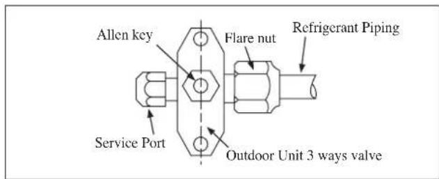
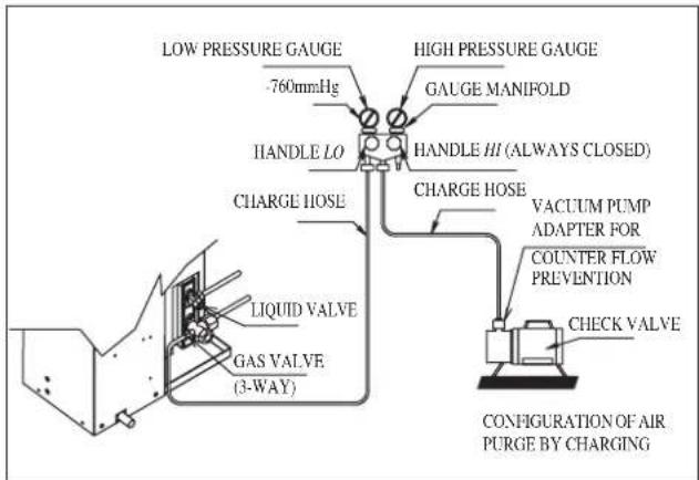
- Remove the caps from the valve and the service port.
- Connect the center of the charging gauge to the vacuum pump.
- Connect the charging gauge to the service port of the 3-way valve.
- Start the vacuum pump. Evacuate for approximately 30 minutes. The evacuation time varies with different vacuum pump capacity. Confirm that the charging gauge needle has moved towards -760mmHg.
Caution
- If the gauge needle does not move to -760mmHg, be sure to check for leakage at flare type connection of the indoor and outdoor unit and repair the leak before proceeding to the next step.
- Close the valve of the changing gauge and stop the vacuum pump.
- On the outdoor unit, open the suction valve (3 way) and liquid valve (2 way) (in anti-clockwise direction) with 4mm key for hexagon sacked screw.
Charge Operation
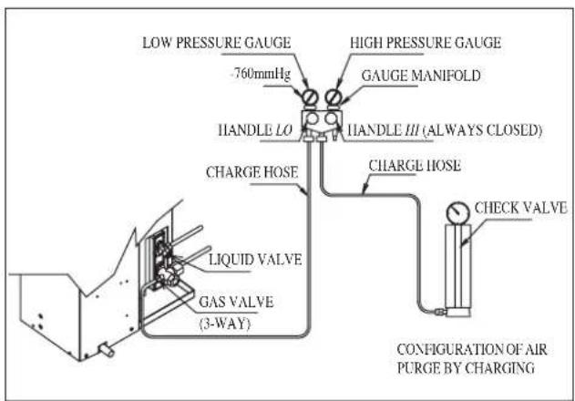
This operation must be done by using a gas cylinder and a precise weighing machine. The additional charge is topped-up into the outdoor unit using the suction valve via the service port.
- Remove the service port cap.
- Connect the low pressure side of the charging gauge to the suction service port center of the cylinder tank and close the high pressure side of the gauge. Purge the air from the service hose.
- Start the air conditioner unit.
- Open the gas cylinder and low pressure charging valve.
- When the required refrigerant quantity is pumped into the unit, close the low pressure side and the gas cylinder valve.
- Disconnect the service hose from service port. Put back the service port cap.
ADDITIONAL CHARGE
The refrigerant is pre-charged in the outdoor unit. If the piping length is less than 7.5m, then additional charge after vacuuming is not necessary. If the piping length is more than 7.5m, then use the additional charge value as indicated in the table.
Additional refrigerant charge [g] per additional 1m length as tabulated
| Model | Indoor (FTXC) | 25 | 35 | 50 | 60 | |
| Outdoor (RXC) | 25 | 35 | 50 | 60 | ||
| Additional charge [g/m] 17 17 17 17 | ||||||
Example:
FTXC25 & RXC25 with 12m piping length, additional piping length is 4.5m. Thus,
Additional charge = 4.5[m] x 17[g/m]
$$ = 7 6. 5 [ \mathrm{g} ] $$
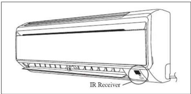
INDICATOR LIGHTS
IR Signal Receiver
When an infrared remote control operating signal has been transmitted, the signal receiver on the indoor unit will respond as below to confirm acceptance of the signal transmission.
| ON to OFF 1 Long Beep | |
| OFF to ON Pump down / Cool force on | 2 Short Beep |
| Others 1 Short Beep |
Cooling Unit/Heat Pump Unit
The table shows the LED indicator lights for the air conditioner unit under normal operation and fault conditions. The LED indicator lights are located at the side of the air conditioner unit.
The heat pump units are equipped with an “auto” mode sensor whereby it will provide reasonable room temperature by switching automatically to either “cool” or “heat” mode according to the temperature set by the user.
LED Indicator Lights for Cooling Unit/Heat Pump Unit

LED Indicator Lights: Normal Operation And Fault Conditions For Cooling/Heat Pump Unit
 |  COOL/HEAT(BLUE/RED) COOL/HEAT(BLUE/RED) |  | Operation |
 | Cool mode | ||
 | Heat mode | ||
 | Auto mode in Heating operation | ||
| [7ZW6] | Auto mode in Cooling operation | ||
| [0846] | ○ | Timer on | |
| ○ | [A870] | Sleep mode on | |
 | Fan mode on | ||
 | Dry mode on | ||
 | Defrost operation | ||
 | Unit error |
ON
Blinking
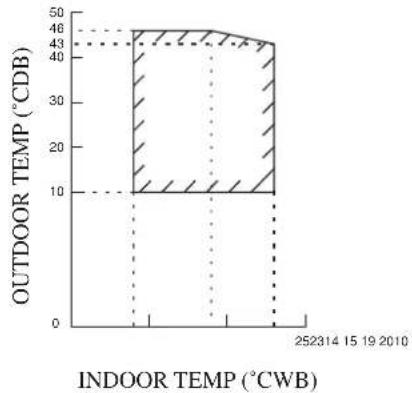
OPERATING RANGE
Heat Pump Model
Model: FTXC 25/35 RXC 25/35
COOLING HEATING
area
| INDOOR TEMP (°CWB) | OUTDOOR TEMP (°CDB) | |---|---| | 252314 | 46 | | 15 | 43 | | 19 | 43 | | 2010 | 43 |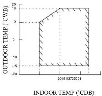
area
| Year | Indoor Temp (°CDB) | Outdoor Temp (°CWB) | | :--- | :--- | :--- | | 2015 | 0.03725201 | -18 | | 2016 | 0.03725201 | -18 | | 2017 | 0.03725201 | -18 | | 2018 | 0.03725201 | -18 | | 2019 | 0.03725201 | -18 | | 2020 | 0.03725201 | -18 | | 2021 | 0.03725201 | -18 | | 2022 | 0.03725201 | -18 | | 2023 | 0.03725201 | -18 | | 2024 | 0.03725201 | -18 | | 2025 | 0.03725201 | -18 | | 2026 | 0.03725201 | -18 | | 2027 | 0.03725201 | -18 | | 2028 | 0.03725201 | -18 | | 2029 | 0.03725201 | -18 | | 2030 | 0.03725201 | -18 | | 2031 | 0.03725201 | -18 | | 2032 | 0.03725201 | -18 | | 2033 | 0.03725201 | -18 | | 2034 | 0.03725201 | -18 | | 2035 | 0.03725201 | -18 | | 2036 | 0.03725201 | -18 | | 2037 | 0.03725201 | -18 | | 2038 | 0.03725201 | -18 | | 2039 | 0.03725201 | -18 | | 2040 | 0.03725201 | -18 | | 2041 | 0.03725201 | -18 | | 2042 | 0.03725201 | -18 | | 2043 | 0.03725201 | -18 | | 2044 | 0.03725201 | -18 | | 2045 | 0.03725201 | -18 | | 2046 | 0.03725201 | -18 | | 2047 | 0.03725201 | -18 | | 2048 | 0.03725201 | -18 | | 2049 | 0.03725201 | -18 | | 2050 | 0.03725201 | -18 | | 2051 | 0.03725201 | -18 | | 2052 | 0.03725201 | -18 | | 2053 | 0.03725201 | -18 | | 2054 | 0.03725201 | -18 | | 2055 | 0.03725201 | -18 | | 2056 | 0.03725201 | -18 | | 2057 | 0.03725201 | -18 | | 2058 | 0.03725201 | -18 | | 2059 | 0.03725201 | -18 | | 2060 | 0.03725201 | -18 | | 2061 | 0.03725201 | -18 | | 2062 | 0.03725201 | -18 | | 2063 | 0.03725201 | -18 | | 2064 | 0.03725201 | -18 | | 2065 | 0.03725201 | -18 | | 2066 | 0.03725201 | -18 | | 2067 | 0.03725201 | -18 | | 2068 | 0.03725201 | -18 | | 2069 | 0.03725201 | -18 | | 2070 | 0.037252 | -18 | | 2 | nan | nan | The chart displays the spatial distribution of outdoor temperature over time (in degrees Celsius). The x-axis represents the time in years (from January to December), and the y-axis represents the temperature in degrees Celsius. There are no labels or additional data series in this image.DB: Dry bulb WB: Wet bulb
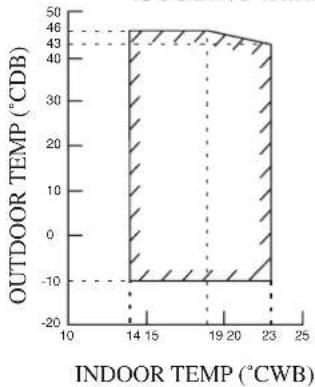
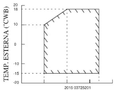
Model: FTXC 50/60 RXC 50/60
COOLING HEATING
bar
| INDOOR TEMPERATURE (°CWB) | OUTDOOR TEMPERATURE (°CDB) | | ------------------------- | -------------------------- | | 14 | 43 | | 19 | 43 | | 23 | 43 |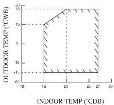
area
| INDOOR TEMP (°CDB) | OUTDOOR TEMP (°CWB) | |---|---| | 15 | 10 | | 20 | 18 | | 27 | -15 | | 30 | -15 |DB: Dry bulb WB: Wet bulb
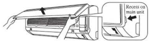
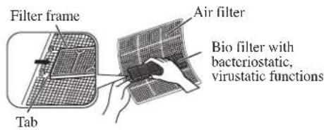
AIR FILTER
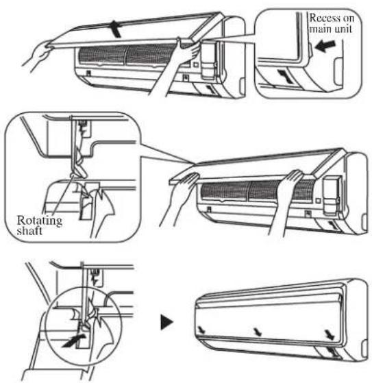
1. Open the front panel.
- Hold the panel at the recesses on the main unit (2 recesses on right and left sides) and lift it until it stops.
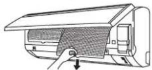
2. Pull out the air filters.
- Push a little upwards the tab at the center of each air filter, then pull it down.
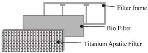
3. Take off the Bio filter with bacteriostatic, virustatic functions.
- Hold the recessed parts of the frame and unhook the four claws.
Titanium Apatite Filter (Bio Filter)
Attached Concept
natural_image
Diagram of a car air conditioner unit with a handle and ventilation grille (no text or symbols)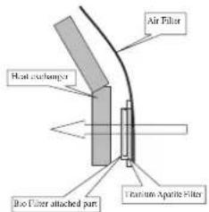
4. Clean or replace each filter.
See figure.
- When shaking off remaining water, do not wring the filter.
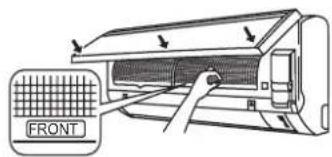
5. Set the air filter and Bio filter with bacteriostatic, virustatic functions as they were and close the front panel.
- Insert claws of the filters into slots of the front panel. Close the front panel slowly and push the panel at the 3 points. (1 on each side and 1 in the middle.)
- The air filter and Bio filter with bacteriostatic, virustatic functions have a symmetrical form in the horizontal direction.
* Bio Filter and Titanium Apatite Filter are optional accessories.
Installation Procedure for Bio Filter
Bio Filter packs in a hermetically-sealed bag.
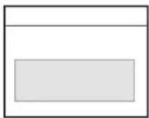
Take it out
at the time of installation.

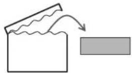

Slip the Filter in between Filter frame and Titanium Apatite Filter.
CAUTION
- Please use this Bio Filter during dry season such as winter.
• Storage, handling and disposal methods.
• The lifetime of this Bio Filter is about a year after opening.
- In case you do not use this Bio Filter right away, please don't place the Bio Filter in any place where it will be subjected to direct sunlight, high temperatures and/or high humidity.
- There can be slight differences between Bio Filter color because of the manufacturing reasons, there is no effect on the unit performance.
- Please open this bag right before you use it. Bio Filter should remain unopened and sealed in its packaging until right before usage. (It may cause performance deterioration or quality change.)
- To avoid danger of suffocation and any unexpected accident, please dispose the plastic bag immediately after you remove the Bio Filter. Keep out of reach of babies and children.
- If you keep this Bio Filter for a long time, please keep it unopened and store in a cool place avoiding direct sunlight.
- Please dispose the old Bio Filter as nonflammable garbage after use.
• Operation with dirty filters:
(1) cannot deodorize the air. (3) results in poor heating or cooling.
(2) cannot clean the air. (4) may cause odour.
• To order Bio Filter, contact the service shop where you bought the air conditioner.
SERVICE AND MAINTENANCE
| Service Parts Maintenance Procedures Period | ||
| Indoor air filter | Remove any dust adhering to the filter by using a vacuum cleaner or wash in lukewarm water (below 40°C/104°F) with a neutral cleaning detergent.2. Rinse the filter well and dry before placing it back onto the unit.3. Do not use gasoline, volatile substances or chemicals to clean the filter. | At least once every 2 weeks.More frequently if necessary. |
| Indoor unit Clean | any dirt or dust on the grille or panel by wiping it with a soft cloth soaked in lukewarm water (below 40°C/104°F) and a neutral detergent solution.2. Do not use gasoline, volatile substances or chemicals to clean the indoor unit. | At least once every 2 weeks.More frequently if necessary. |

CAUTION
- Avoid direct contact of any coil treatment cleaners on plastic part. This may cause plastic part to deform as a result of chemical reaction.
1. Open the front panel.
- Hold the panel at the recesses on the main unit (2 recesses on right and left sides) and lift it until it stops.
2. Remove the front panel.
- While lifting the front panel further, slide it to the right and pull it to the front side. The left rotating shaft is detached. Slide the right rotating shaft to the left and pull it to the front side to remove it.
3. Attach the front panel.
- Align the right and left rotating shafts of the front panel with the grooves and push them all the way in.
- Gently close the front panel. (Push both ends and the center on the front panel.)
CAUTION
- Don't touch the metal parts of the indoor unit. It may cause an injury.
- When removing or attaching the front panel, support the panel securely with hand to prevent it from falling.
- For cleaning, do not use hot water above 40^ C, benzine, gasoline, thinner, nor other volatile oils, polishing compound, scrubbing brushes, nor other hand stuff.
• After cleaning, make sure that the front panel is securely fixed.
When The Unit Is Not To Be Used For An Extended Long Period Of Time
| Operate the unit for 2 hours with the following setting.Operating mode : coolTemperature : 30°C/86°F |  | Remove the power plug.If you are using an independent electric circuit for your unit, cut off the circuit.Remove the batteries in the remote control. | 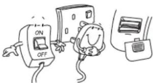 |
TROUBLESHOOTING
For any enquiries on spare part, please contact your authorized dealer. When any malfunction of the air conditioner unit is noted, immediately switch off the power supply to the unit. Check the following fault conditions and causes for some simple troubleshooting tips.
| Fault Causes / Action | |
| 1. Fbetection page is done in the operation.3 Main features after minutes conditioner unit is started. | – for the compressor to start operating. |
| The air conditioner unit does not operate.2. Power failure, | or the fuse needs to be replaced.– The power plug is disconnected.– It is possible that your delay timer has been set incorrectly.– If the fault persist after all these verifications, please contact the air conditioner unit installer. |
| The air flow is too low.3. The air filter is dirty. | –– The doors or windows are open.– The air suction and discharge are clogged.– The regulated temperature is not high enough. |
| Discharge air flow has bad odour.4. Odours may be caused by cigarettes, smoke particles, perfume etc. which might have adhered onto the coil. | |
| Condensation on the front air grille of the indoor unit.5. This is caused by air humidity after an extended long period of operation.– The set temperature is too low, increase the temperature setting and operate the unit at high fan speed. | |
| Water flowing out from the air conditioner unit.6. Switch off unit and call dealer. | |
If the fault persists, please call your local dealer / serviceman.
DISEGNI E DIMENSIONIS
Inverter (Power Outdoor)
area
| Date | Temperature (°CDB) | | :--- | :--- | | 25/23/14 | 43 | | 15 | 46 | | 19 | 43 | | 20/20/10 | 43 | The chart displays a single data series representing total temperature over time. The top segment is shaded with diagonal hatching, and the bottom segment is dotted with horizontal lines. No explicit numerical values are provided for the data series.TEMP. INTERNA (°CWB)
area
| Date | Temperature Esterna (°CWB) | | :--- | :--- | | 2015-03725201 | -18 | | 2015-03725201 | -15 | | 2015-03725201 | 10 | | 2015-03725201 | 18 |TEMP. INTERNA (°CDB)
DB: Termometro asciutto WB: Termometro bagnato
Modello: FTXC 50/60 RXC 50/60
natural_image
Line drawing of a car air conditioner unit with a mesh grille and handle (no text or symbols)
(1) GWP = Treibhauspotential
Inverter (Power Outdoor)

natural_image
Line drawing of a car air conditioner unit with a handle and ventilation grille (no text or symbols)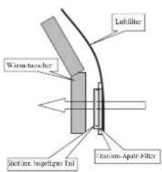
Unidad interior [FTXC]
Unidad interior [FTXC]
![DAIKIN RXC50AV1B - Unidad interior [FTXC] - 1](/content/2026/04/669707/images/664275dc0dbe5fc33c6b56c81aaa074e2967d24ba521acc4baa9291d45addf1a.jpg)
Unidad interior [FTXC]
![DAIKIN RXC50AV1B - Unidad interior [FTXC] - 2](/content/2026/04/669707/images/2b9c4725f7b3e8a055f94bf01bebc94edce8def48d1dba2acc2d85b4f2c3cdf4.jpg)
Inversor (Outdoor Power)
![DAIKIN RXC50AV1B - Unidad interior [FTXC] - 3](/content/2026/04/669707/images/85af99adc505d279a47f012ad48ae62106a31d282e1b81733c3ad0d44502409c.jpg)
natural_image
Line drawing of a car air conditioner unit with a hand inserting a mesh component (no text or symbols)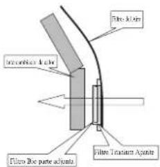
MANUEL D'INSTALLATION
| Tuyau, mm (pouce) Couple, Nm / (ft-lb) | |
| 6,35 (1/4") 18 (13,3) | |
| 9,52 (3/8") 42 (31,0) | |
| 12,70 (1/2") 55 (40,6) | |
| 15,88 (5/8") 65 (48,0) | |
| 19,05 (3/4") 78 (57,6) | |
Inverter (Power Outdoor)
natural_image
Technical line drawing of a mechanical component with a meshed base and mounting bracket (no text or symbols)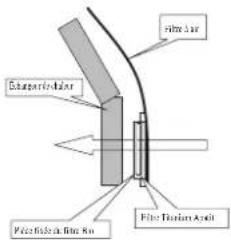
natural_image
Technical line drawing of a door frame with labeled dimensions E and F (no text or symbols beyond labels)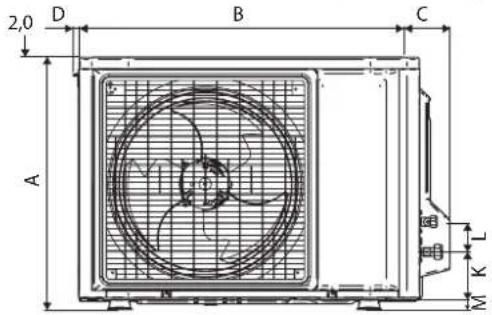
natural_image
Technical line drawing of a mechanical device with internal components (no text or symbols)| Modeller\Boyutlar | A | B | C | D | E | F | G | H | I | J | K | L | M | N | O | ||
| 25/35 550 658 51 11 2 | 73 16 | 14 47 | 0 96 9 | 3 94 | 60 14 | 133 8 | 10 29 | 9 |
| Modeller\Boyutlar | A | B | C | D | E | F | G | H | I | J | K | L | M | N | |
| 50 | 855 | 628 | 328 | 520 | 179 | 46 | 93 | 149 | 101 | 113 | 603 | 126 | 164 | 15 | 34 |
| 60 | 855 | 730 | 328 | 520 | 179 | 46 | 93 | 149 | 101 | 113 | 603 | 126 | 164 | 15 | 34 |
| Modeller\Boyutlar | P | Q | R | S | T | U | V |
| 50 | 23 | 362 | 73 | 75 | 8 | 67 | 7 |
| 60 | 23 | 362 | 73 | 75 | 8 | 67 | 7 |
KURULUM KILAVUZU
area
НАРУЖНАЯ ТЕМПЕРАТУРА (°CWB) | Date | Temperature (°CWB) | |---|---| | 03/15 | 10 | | 03/16 | 12 | | 03/17 | 14 | | 03/18 | 16 | | 03/19 | 18 | | 03/20 | 18 | The chart displays a shaded area representing temperature variation over time. The x-axis is labeled as "2015 03725201", and the y-axis is labeled as "НАРУЖНАЯ ТЕМПЕРАТУРА (°CWB)". There are no additional data series or categories visible in the image.bar
HAPYKHAR TEMPERATURA (°CDB) | Temperature (°CDB) | Value | | :--- | :--- | | 14 | -10 | | 15 | 46 | | 19 | -10 | | 23 | 43 | The chart displays a single vertical bar centered at 14, indicating a temperature range of approximately 46 to 43 degrees Celsius. Error bars are present but lack explicit labels or data series.natural_image
Diagram of a car air conditioner unit with a handle and ventilation grille (no text or symbols)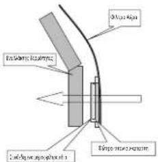
Note: The chart shows the original text in the original text of the Dossier de Construction Technique.
Note: The chart shows the original text in the original text of the Dossier de Construction Technique.
Note: The chart shows the original text in the original text of the Dossier de Construction Technique.
Note: The chart shows the original text in the original text of the Dossier de Construction Technique.
Note: The chart shows the original text in the original text of the Dossier de Construction Technique.
Note: The chart displays the original text in the original text of the Dossier de Construction Technique.
Note: The chart displays the original text in the original text of the Dossier de Construction Technique.
Note: The chart displays the original text in the original text of the Dossier de Construction Technique.
Note: The chart displays the original text in the original text of the Dossier de Construction Technique.
Note: The chart displays the original text in the original text of the Dossier de Construction Technique.
Note: The chart illustrates the original text in the original text of the Dossier de Construction Technique.
Note: The chart displays the original text in the original text of the Dossier de Construction Technique.
Note: The chart illustrates the original text in the original text of the Dossier de Construction Technique.
Note: The chart displays the original text in the original text of the Dossier de Construction Technique.
Note: The chart illustrates the original text in the original text of the Dossier de Construction Technique.
Note: The chart illustrates the original text in the original text of the Dossier de Construction Technique.
Note: The chart illustrates the original text in the original text of the Dossier de Construction Technique.
Note: The chart displays the original text in the original text of the Dossier de Construction Technique.
Note: The chart illustrates the original text in the original text of the Dossier de Construction Technique.
Note: The chart displays the original text in the original text of the Dossier de Construction Technique.
Note: The chart highlights that
Tan Yong Cheem General Manager
Issue Date:09 Dec 2016
3, Lot 60334, Persiaran Bukit Rahma Taman Perindustrian Bukit Rahman Putra, 47000 Sungai Buloh, Selangor Darul Ehsan, Malaysia.
3SLY-C V0
| CE - DECLARATION-OF-CONFORMITY | CE - DECLARACION-DE-CONFORMIDAD | CE - DECLARAÇÃO-DE-CONFORMIDADE | CE - ERKLÆRING OM-SAMSVAR | CE - IZJAVA-O-USKLÆDENOSTI | CE - IZJAVA O SKLADNOSTI | CE - ATITIKTIES-DEKLARACIJA |
| CE - KONFORMITÄTŠERKLÁRUNG | CE - DICHIARAZIONE-DI-CONFORMITA | CE - 3AÆBLEHIE-O-COOTBETCTBIII | CE - ILMOITUŞ-YHĐENMUKAISUUDESTA | CE - MEGFELELOSEĞI-NYILATKOZAT | CE - VASTAVUSDEKLARATSIOON | CE - ATBILSTAS-DEKLARACIJA |
| CE - DECLARATION-DE-CONFORMITE | CE - ΔΗΛΩΣΗ ΣΥΜΜΟΡΦΩΣΗΣ | CE - OVERENSSTEMMELSESERKLÆRING | CE - PROHLÅSENI-O-SHODĘ | CE - DEKLARACJA-ZGODNOŚCI | CE - DEKŁPARAÇIJA-3A-СЪОТВЕТСТВИЕ | CE - VYHLASENIE-ZHODY |
| CE - CONFORMITEITSVERKLARING | CE - FÓRSÁKRAN-OM-ÖVERENSTÄMMELSE | CE - DECLARAȚIE-DE-CONFORMITATE | CE - UYUMLULUK-BEYANI |
DAIKIN MALAYSIA SDN. BHD.
01(GB) declares under its sole responsibility that the air conditioning models to which this declaration relates:
At 6.5% (and one kind) in case and again, the first additional data is available to be available for
(1) 2016, 10:47, 10:48, 10:49, 10:50, 10:51, 10:52, 10:53, 10:54, 10:55, 10:56, 10:57, 10:58, 10:59, 10:60, 10:61, 10:62, 10:63, 10:64, 10:65, 10:66, 10:67, 10:68, 10:69, 10:70, 10:71, 10:72, 10:73, 10:74, 10:75, 10:76, 10:77, 10:78, 10:79, 10:80, 10:81, 10:82, 10:83, 10:84, 10:85, 10:86, 10:87, 10:88, 10:89, 10:90, 10:91, 10:92, 10:93, 10:94, 10:95, 10:96, 10:97, 10:98, 10:99, 11:00, 11:01, 11:02, 11:03, 11:04, 11:05, 11:06, 11:07, 11:08, 11:09, 11:10, 11:11, 11:12, 11:13, 11:14, 11:15, 11:16, 11:17, 11:18, 11:19, 11:20, 11:21, 11:22, 11:23, 11:24, 11:25, 11:26, 11:27, 11:28, 11:29, 11:30, 11:31, 11:32, 11:33, 11:34, 11:35, 11:36, 11:37, 11:38, 11:39, 12:00
RXC25AV1B, RXC35AV1B
12.4. Subsidiaries (or not known), (or not known).
01 Note * as set out in and judged positively by 06 Nota * delineable e judicato pos
according to the Certificate
- Drakin Europe N.V. is proposed to compile the Tensional Construction File. 07. H. Dink
20.1. Berlin, Europe N.V. is authorised to copy the 30% Fair Collection No.
Issue Date: 09 Dec 2016


3SLY-F V0
| < A > | OYLR&D-054-EMC |
| < B > | INTERTEK SEMKO AB(NB0413) |
| < C > | 1620320 |
19** Daikin Europe N.V. je podblašben za sestavo datoteke s tehnično mapo.
01(GB) declares under its sole responsibility that the air conditioning models to which this declaration relates:
- Đ erklärt auf seine alleinige Verantwortung daß die Modelle der Klageräre für die diese Erklärung bestimmt ist
- Đ declare sous sa seule responsabilité que os appareils d'air conditionné visés par la présente déclaration:
- NL verdictar hier bi een gen exclusieve verantwoordelijkneid de ar a conditioning units waarop deze verklaring betrekking heeft:
- Đ declare baja su única responsabilidad que los modelos de ara acondicionado a los cuales hace referencia la déclaration:
- ① dicha sottu sua responsabilité che i condicionation modelo o así è riferta questa dichiarazione:
- GR Şİkjavuje amokisokrış men şübing en ta povráska tuw vklum ortaków onkaskivem cme moeda evapiperatur mapólica Şİkjavu:
- P declare sob sua exclusiva responsabilidade que os modelos de ar condicionado a que este declaração se refere:
FTXC25AV1B, FTXC35AV1B, FTXC50AV1B, FTXC60AV1B,
| 01 are in conformity with the following standard(s) or other normative document(s), provided that these are used in accordance with our instructions: | 08 estão em conformidade com at(e) seguinte(s) norma(s) ou outro(s) documento(s) normativo(s), desde que estes sejam utilizados de acordo com as nossas instrupées. | 16 negleterek az alábi szanávýjoknak vagy egyb irányacó dokumentum(joknak, ha azokat ebitlás szerint hasznělják; |
| 02 denden fogenden Nom(ren) oder einem anderen Nomnökument oder -dokumenter entsorichtentsorechen, unter der Voraussetzung, daß sie gemás unseren Anweisungen ergesetzt werden: | 09 соответsteuer следующим стандартam или други нормативным документам, том условим и использования согласно нашими инструкции: | 17 spelnija zymogi naspejouçych nom i innych dokumentów normalizacyjnych, pod warunkem že używane są zgodnie z raszymi instrukcijani: |
| 03 sont conformes à laixa norma(s) ou autre(s) document(s) normall(s), pour autant qu'ils sovent utilisés conformément à nos instructions: | 10 overnoder folgende standard(er) eller ander/andre retningsgivende dokument(er), fouscat at disse anvendes i berhoic tl vore instrukser: | 18 sunt in conformitate cu umázonul (urmátocarele) standard(e); sau at(e) document(e) normativ(e), cu condija za acestea sá fe utilizate în conformitate cu instruktionile roestre: |
| 04 conform de volgende norm(en) of één de meer andere bindende documenten zijn, op voorwaarde dat ze worden gebruikt overeenkomstig orze instructees: | 11 respective ustrasting är utföd i överensstämme med och föjer föjande standardier) eller andra normgivende dokument, under forutsätning att användring sker i överensstämme med våra instrukcerer: | 19 skladni z nasledními standardı in drugníi normativ, pod pogojem, da se uaporabljao v skladu z našni navoditi: |
| 05 están en conformidad con la(s) siguiente(s) norma(s) u otro(s) documento(s) normativo(s), siempre que sean utilizados de acuerdo con nuestras instrucciones: | 12 respective ústyr er i overensstemme med folgende standardier) eller andre normgivende dokumentier), under forutsätning av at disse brukes i herhoic tl våra instrukcer: | 20 on vastavises järgmistje standanditelga vii teste normalvisete dokumentcega, ku neid kasuzatkse vastavati meie junendele: |
| 06 sont conformiti a(t) sequenta(t) standard(s) o alto(t) documentati) a canaltone normative, a palle che vengano usal in conformità alle incste istruzione: | 13 respective ústyr er i overensstemme med folgende standardier) eller andre normgivende dokumentier), under forutsätning av at disse brukes i herhoic tl våra instrukcer: | 21 obvictaat na следicate standardy mit други нормативным документy, при усилке, на се волоюват зъръзасно нашите инструкции: |
| 07 evon cuqupova pe rato t'inkovoujo(s) npromu(o) ŷ ákko svýpropo(o) kovovopov, umb tvro spočmotéam om gynaputomotivno cýqupovo pe tiis obýnos μος: | 14 vastavat seuravaen standarden ja muden ohjeelisten dokumentien vaatimursia ecelýtráen, että nitá käytetáan ohjećenne mukaisesti: | 22 atitika žemiu nurocytus stancartus ir (arba) ititus nominulus dokumentus su sayga, kad yra naudojami pagal niúsy nurodymus: |
| 14 za predpakadu, že jsou využívany v souladu s našnii poikyny, odpovidaji násedujícím normám nebo normativním dokumentím: | 23 rad, ja ieloti atkostii raždaja noradijami, atistit seviropistem standariem un citem normativním dokumentiem: | |
| 15 u skladu sa siječedim standardom(ims) tl drugim normativním dokumentim(maj), uz uvjet da se ori korise u skladu s našni uputana: | 24 sú v zhode s nasledovrouj(km) normoutami) aklo irýjmi' normativým(i) dokumentum(ami), za predpakladu, že sa použňaju v sálade s našni návodom: | |
| 25 ünitún, taismallamam za göre vullanlasí kosytuvla agačjdavi standartar ve norm belirter belgelete uynumudur: |
EN60335-2-40.
01 following the provisions of: 10 under iagttagelse af bestemme serne b 19 ob upoštevanju določo:
Issue Date: 09 Dec 2016
- In the event that there is any conflict in the interpretation of this manual and any translation of the same in any language, the English version of this manual shall prevail.
- The manufacturer reserves the right to revise any of the specification and design contain herein at any time without prior notification.
- Nel caso ci fossero conflitti nell'interpretazione di questo manuale o delle sue stesse traduzioni in altre lingue, la versione in lingua inglese prevale.
- Il fabbricante mantiene il diritto di cambiare qualsiasi specificazione e disegno contenuti qui senza precedente notifica.
- Im Falle einer widersprüchlichen Auslegung der vorliegenden Anleitung bzw. einer ihrer Übersetzungen gilt die Ausführung in Englisch.
- Änderungen von Design und technischen Merkmalen der in dieser Anleitung beschriebenen Geräte bleiben dem Hersteller jederzeit vorbehalten.
- En caso de conflicto en la interpretación de este manual, y en su traducción a cualquier idioma, prevalecerá la versión inglesa.
- El fabricante se reserva el derecho a modificar cualquiera de las especificaciones y diseños contenidos en el presente manual en cualquier momento y sin notificación previa.
- En cas de désaccord sur l'interprétation de ce manuel ou une de ses traductions, la version anglaise fera autorité.
- Le fabriquant se réserve le droit de modifier à tout moment et sans préavis la conception et les caractéristiques techniques des appareils présentés dans ce manuel.
- Bu kılavuzun anlaşılmasında bir çatışma olduğunda ve farklı dillerdeki tercümeler farklılık gösterdiğinde, bu kılavuzun ingilizce sürümü üstün tutulacaktır.
- Üretici burada bulunan teknik özellikleri ve tasarımları herhangi bir zamanda ve önceden haber vermeden değiştirme hakkını saklı tutar.
- В случае противоречия перевода данного руководства с другими переводами одного и того же текста, английский вариант рассматривается как приоритетный.
- Завод-изготовитель оставляет за собой право изменять характеристики и конструкцию в любое время без предварительного уведомления.
- Σε περίπτωση διαφορών μεταξύ του εγχειριδίου αυτού και τυχόν μετάφρασής του σε οποιαδήποτε γλώσσα, υπερισχύει η Αγγλική έκδοση αυτού του εγχειριδίου.
- Ο κατασκευαστής διατηρεί το δικαίωμα αναθεώρησης των προδιαγραφών και σχεδίων που περιέχονται στο παρόν οποιαδήποτε στιγμή χωρίς προηγούμενη ειδοποίηση.
DAIKIN EUROPE N.V.
P.O.Box 18674, Jebel Ali Free Zone, Dubai-UAE
Email: info@daikinmea.com
Web: www.daikinmea.com
Importer for Turkey
DAIKIN ISITMA ve SOĞUTMA SISTEMLERI SAN TIC A.Ş.
Allianz Plaza-Kucukbakkalkoy Mah.Kayısdagi Cad.No:1 34750
Atasehir-ISTANBUL / TURKIYÉ
DAIKIN INDUSTRIES, LTD.
Head office:
Umeda Center Bldg., 2-4-12, Nakazaki-Nishi, Kita-ku, Osaka, 530-8323 Japan
Tokyo offi ce:
JR Shinagawa East Bldg., 2-18-1, Konan,
Minato-ku, Tokyo, 108-0075 Japan
http://www.daikin.com/global/
DAIKIN MALAYSIA SDN. BHD.
Lot 60334, Persiaran Bukit Rahman Putra 3,
Taman Perindustrian Bukit Rahman Putra,
47000 Sungai Buloh, Selangor Darul Ehsan, Malaysia.