
EG4500CL - Generator Honda - Free user manual and instructions
Find the device manual for free EG4500CL Honda in PDF.

| Product Type | Honda EG4500CL Electric Generator |
| Brand | Honda |
| Model | EG4500CL |
| Engine | GX390, 4-stroke single cylinder, 389 cm³, 8.2:1, 3000 rpm |
| Ignition Type | CDI electromagnetic ignition |
| Recommended Spark Plug | BPR5ES (NGK) |
| Fuel | Unleaded gasoline (octane rating 91 RON min) |
| Fuel Tank Capacity | 24,0 liters |
| Engine Oil | SAE 10W-30 (API SE or higher), 1,1 liter |
| Rated AC Output | 4,0 kVA (230 V) / 3,68 kVA (115/230 V) |
| Maximum AC Output | 4,5 kVA (230 V) / 3,68 kVA (115/230 V) |
| Rated Voltage | 230 V single-phase (or 115/230 V depending on type) |
| Frequency | 50 Hz |
| Rated Current | 17,4 A (230 V) / 32,0 A (115 V) |
| Dimensions (L × W × H) | 681 × 530 × 571 mm |
| Dry Weight | 79,5 kg |
| Sound Level (acoustic pressure) | 81 dB(A) (at operator station) |
| Safety | Oil level detection, automatic shutdown on overspeed and abnormal voltage, AC circuit protectors |
| Starting Method | Manual recoil starter |
| Routine Maintenance | Oil change (every 3 months/50 h), air filter cleaning (every 6 months/100 h), spark plug (every year/300 h) |
| Optional Accessories | Wheel kit (2 or 4 wheels), transport handles |
Frequently Asked Questions - EG4500CL Honda
User questions about EG4500CL Honda
0 question about this device. Answer the ones you know or ask your own.
Ask a new question about this device
Download the instructions for your Generator in PDF format for free! Find your manual EG4500CL - Honda and take your electronic device back in hand. On this page are published all the documents necessary for the use of your device. EG4500CL by Honda.
USER MANUAL EG4500CL Honda
natural_image
Line drawing of a mechanical device with internal components (no text or symbols)
ECOLOGY CONSCIOUS TECHNOLOGY
OWNER'S MANUAL
MANUEL DE L'UTILISATEUR
BEDIENUNGSANLEITUNG
Original instructions
MANUEL DE L'UTILISATEUR
Notice originale
BEDIENUNGSANLEITUNG
Thank you for purchasing a Honda generator.
This manual covers operation and maintenance of the EG3600CL·EG4500CL·EG5500CL generators.
All information in this publication is based on the latest product information available at the time of approval for printing.
Honda Motor Co., Ltd. reserves the right to make changes at any time without notice and without incurring any obligation.
No part of this publication may be reproduced without written permission.
This manual should be considered a permanent part of the generator and should remain with it if it is resold.
Pay special attention to statements preceded by the following words:
⚠ WARNING Indicates a strong possibility of severe personal injury or death if instructions are not followed.
CAUTION: Indicates a possibility of personal injury or equipment damage if instructions are not followed.
NOTE: Gives helpful information.
If a problem should arise, or if you have any questions about the generator, consult an authorized Honda dealer.
▲WARNING
Honda generator is designed to give safe and dependable service if operated according to instructions. Read and understand the Owner's Manual before operating the generator. Failure to do so could result in personal injury or equipment damage.
The illustrations herein are mainly based on: EU type
- The illustration may vary according to the type.
1.SAFETY INSTRUCTIONS ....3
2.SAFETY LABEL LOCATIONS....7
CE mark and noise label locations.... 10
3.COMPONENT IDENTIFICATION.... 11
4.PRE-OPERATION CHECK 17
5. STARTING THE ENGINE....22
• High altitude operation
6.GENERATOR USE.... 26
7.STOPPING THE ENGINE 33
8.MAINTENANCE.... 35
9. TRANSPORTING/STORAGE 43
10.TROUBLESHOOTING 47
11.SPECIFICATIONS 49
12.INSTALLATION OF KIT PARTS....52
13.WIRING DIAGRAM 55
SWITCH CONNECTIONS 55
RECEPTACLE....56
MAJOR Honda DISTRIBUTOR ADDRESSES ......inside back cover
"EC Declaration of Conformity"
CONTENT OUTLINE......inside back cover
IMPORTANT SAFETY INFORMATION
Honda generators are designed for use with electrical equipment that has suitable power requirements. Other uses can result in injury to the operator or damage to the generator and other property.
Most injuries or property damage can be prevented if you follow all instructions in this manual and on the generator. The most common hazards are discussed below, along with the best way to protect yourself and others.
Never attempt to modify the generator. It can cause an accident as well as damage to the generator and appliances.
- Do not connect an extension to the muffler.
- Do not modify the intake system.
- Do not adjust the governor.
- Do not remove the control panel or do not change the wiring of the control panel.
Operator Responsibility
Know how to stop the generator quickly in case of emergency. Understand the use of all generator controls, output receptacles, and connections.
Be sure that anyone who operates the generator receives proper instruction. Do not let children operate the generator without parental supervision.
Be sure to observe the instructions in this manual for how to use the generator and maintenance information. Ignoring or improperly following the instructions can cause an accident such as an electric shock, and the condition of the exhaust gas may deteriorate.
Obey all applicable laws and regulations where the generator is used.
Gasoline and Oil is toxic. Follow the instructions provided by each manufacturer before use.
Place the generator on a firm level place before operation.
Do not operate the generator with any cover removed. You may get your hand or foot caught in the generator and it may cause accident.
Consult your authorized Honda dealer for disassembly and service of the generator that are not covered in this manual.
Carbon Monoxide Hazards
Exhaust contains poisonous carbon monoxide, a colorless, odorless gas. Breathing exhaust can cause loss of consciousness and may lead to death.
If you run the generator in an area that is confined, or even partially enclosed area, the air you breathe could contain a dangerous amount of exhaust gas.
Never run your generator inside a garage, house, or near open windows or doors.
Electric Shock Hazards
The generator produces enough electric power to cause a serious shock or electrocution if misused.
Using a generator or electrical appliance in wet conditions, such as rain or snow, or near a pool or sprinkler system, or when your hands are wet, could result in electrocution.
Keep the generator dry.
If the generator is stored outdoors, unprotected from the weather, check all of the electrical components on the control panel before each use. Moisture or ice can cause a malfunction or short circuit in electrical components that could result in electrocution.
If you get an electric shock, consult a doctor and have medical treatment immediately.
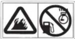
Fire and Burn Hazards
Do not use the generator in areas with a high risk of fire.
The exhaust system gets hot enough to ignite some materials.
- Keep the generator at least 1 meter (3 feet) away from buildings and other equipment during operation.
- Do not enclose the generator in any structure.
- Keep flammable materials away from the generator.
Some parts of the internal combustion engine are hot and may cause burns. Pay attention to the warnings on the generator.
The muffler becomes very hot during operation and remains hot for a while after stopping the engine. Be careful not to touch the muffler while it is hot. Let the engine cool before storing the generator indoors.
Do not pour the water directly on the generator to put out the fire when it occurs. Use an appropriate fire extinguisher specially designed for electric fire or oil fire.
If you inhale fumes produced by an accidental fire with the generator, consult a doctor and have medical treatment immediately.
Refuel With Care
Gasoline is extremely flammable, and gasoline vapor can explode. Allow the engine to cool if the generator has been in operation.
Refuel only outdoors in a well ventilated area with the engine off.
Do not refuel during operation.
Do not overfill the fuel tank.
Never smoke near gasoline, and keep other flames and sparks away.
Always store gasoline in an approved container.
Make sure that any spilled fuel has been wiped up before starting the engine.
Explosion proof
This generator is not complaint with explosion proof.
Disposal
To protect the environment, do not dispose of the used generator, battery, engine oil, etc. carelessly by leaving them in the waste. Observe the local laws or regulations or consult your authorized Honda generator dealer to dispose of these parts.
Please dispose of used motor oil in a manner that is compatible with the environment. We suggest you take it in a sealed container to your local service station for reclamation. Do not throw it in the trash or pour it on the ground.
An improperly disposed battery can hurt the environment. Always confirm local regulations for battery disposal. Contact your servicing dealer for a replacement.
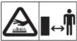
These labels warn you of potential hazards that can cause serious injury. Read the labels and safety notes and precautions described in this manual carefully.
If a label comes off or becomes hard to read, contact your servicing dealer for a replacement.
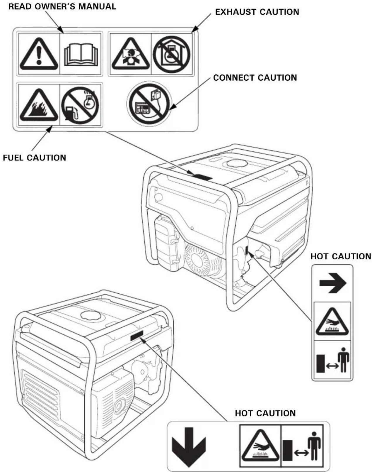
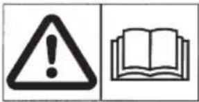
- Honda generator is designed to give safe and dependable service if operated according to instructions. Read and understand the Owner's Manual before operating the generator. Failure to do so could result in personal injury or equipment damage.
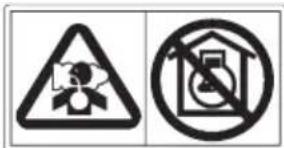
- Exhaust contains poisonous carbon monoxide, a colorless, odorless gas. Breathing carbon monoxide can cause loss of consciousness and may lead to death.
- If you run the generator in an area that is confined, or even partially enclosed area, the air you breathe could contain a dangerous amount of exhaust gas.
- Never run your generator inside a garage, house or near open windows or doors.
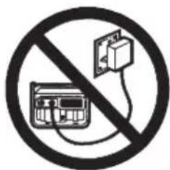
- Improper connections to a building's electrical system can allow current from the generator to backfeed into the utility lines. Such backfeed may electrocute utility company workers or others who contact the lines during a power outage, and the generator may explode, burn, or cause fires when utility power is restored. Consult the utility company or a qualified electrician prior to making any power connections.
- A hot exhaust system can cause serious burns. Avoid contact if the engine has been running.
- Gasoline is highly flammable and explosive. Turn the engine off and let it cool before refueling.
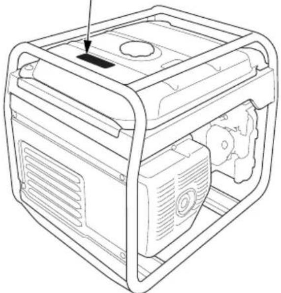
• CE mark and noise label locations
NOISE LABEL AND CE MARK
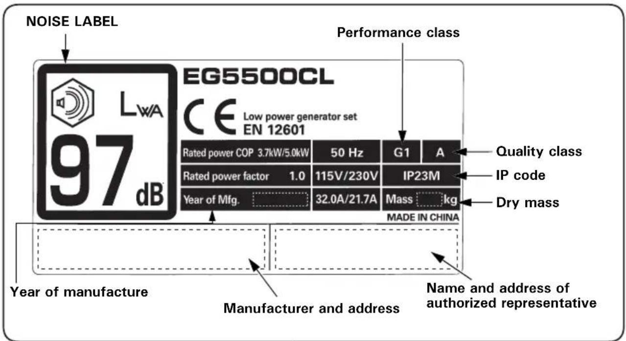
[Example: EG5500CL (BT type)]
natural_image
Line drawing of a portable electric box with ventilation slots and a central vent (no text or symbols)Name and address of manufacturer and authorized representative are written in the "EC Declaration of Conformity" CONTENT OUTLINE in this Owner's Manual.
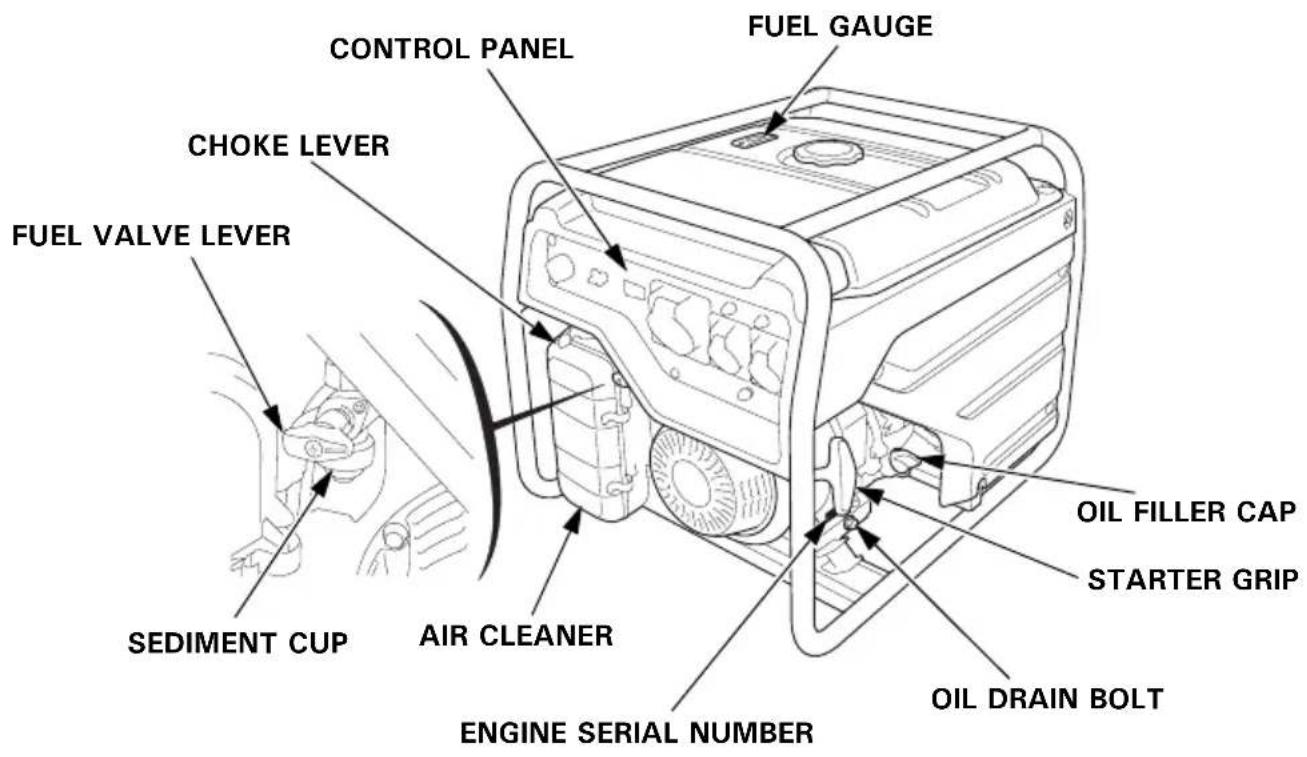
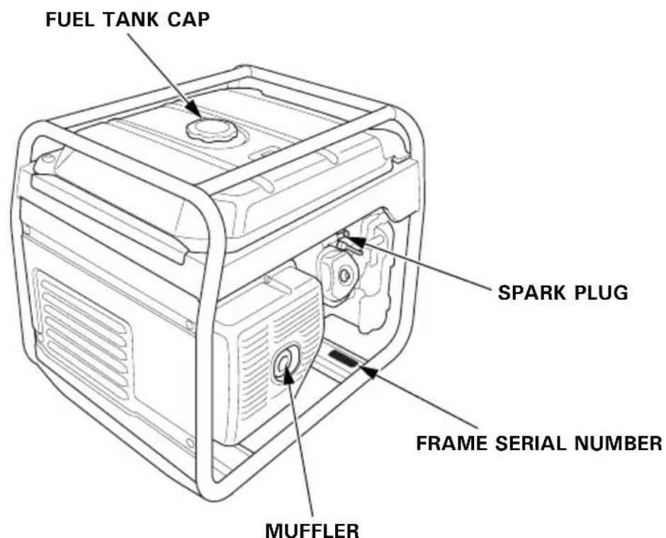
Record the frame serial number and the engine serial number in the spaces below. You will need these serial numbers when ordering parts.
Frame serial number:
Engine serial number:
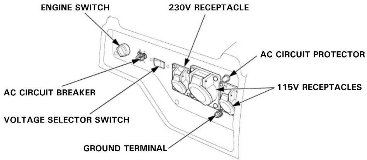
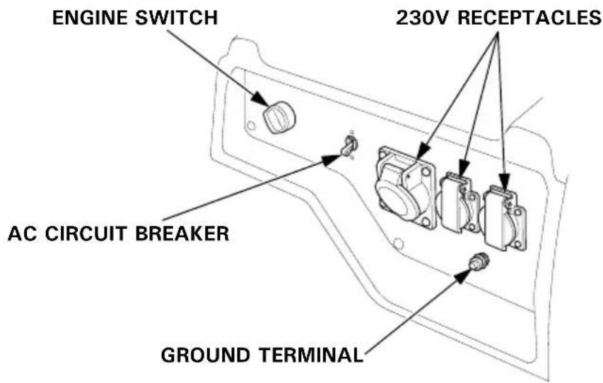
CONTROL PANEL
EG3600CL: BT type
EG3600CL: FT type
EG3600CL: ITT type
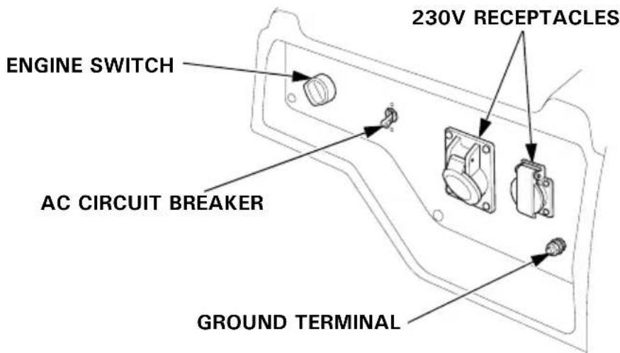
EG3600CL, EG4500CL, EG5500CL: GT, GWT, CLT types
*: Except EG3600CL
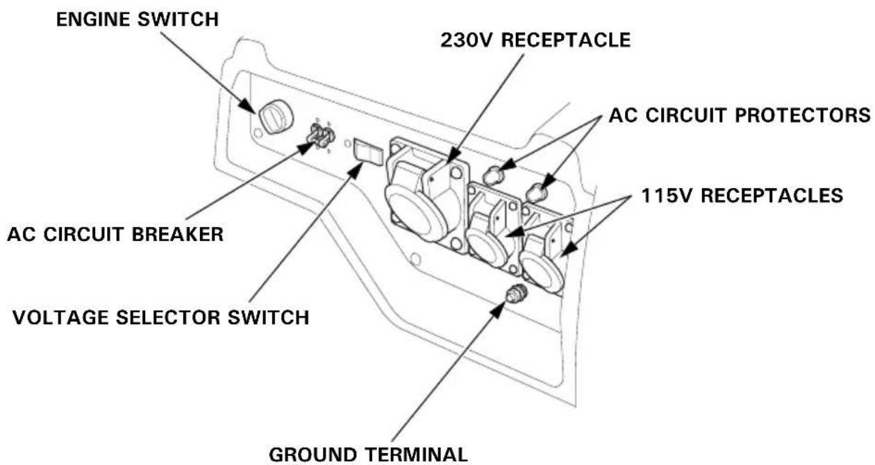
EG4500CL, EG5500CL: BT type
EG4500CL, EG5500CL: FT type
EG4500CL, EG5500CL: ITT type
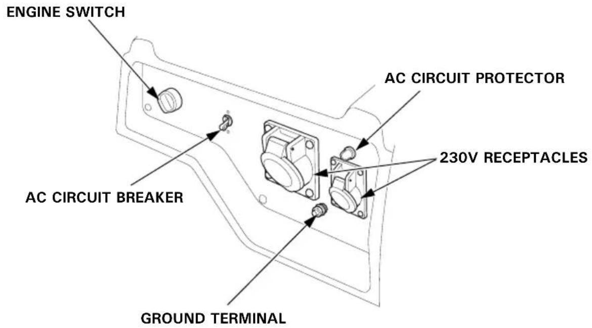
AC Circuit Protectors
The AC circuit protectors will automatically switch OFF if there is a short circuit or a significant overload of the generator at each receptacle. If an AC circuit protector switches OFF automatically, check that the appliance is working properly and does not exceed the rated load capacity of the circuit before resetting the AC circuit protector ON.
EG3600CL: BT type
EG4500CL, EG5500CL: BT type
EG4500CL, EG5500CL: GT, GWT, CLT types
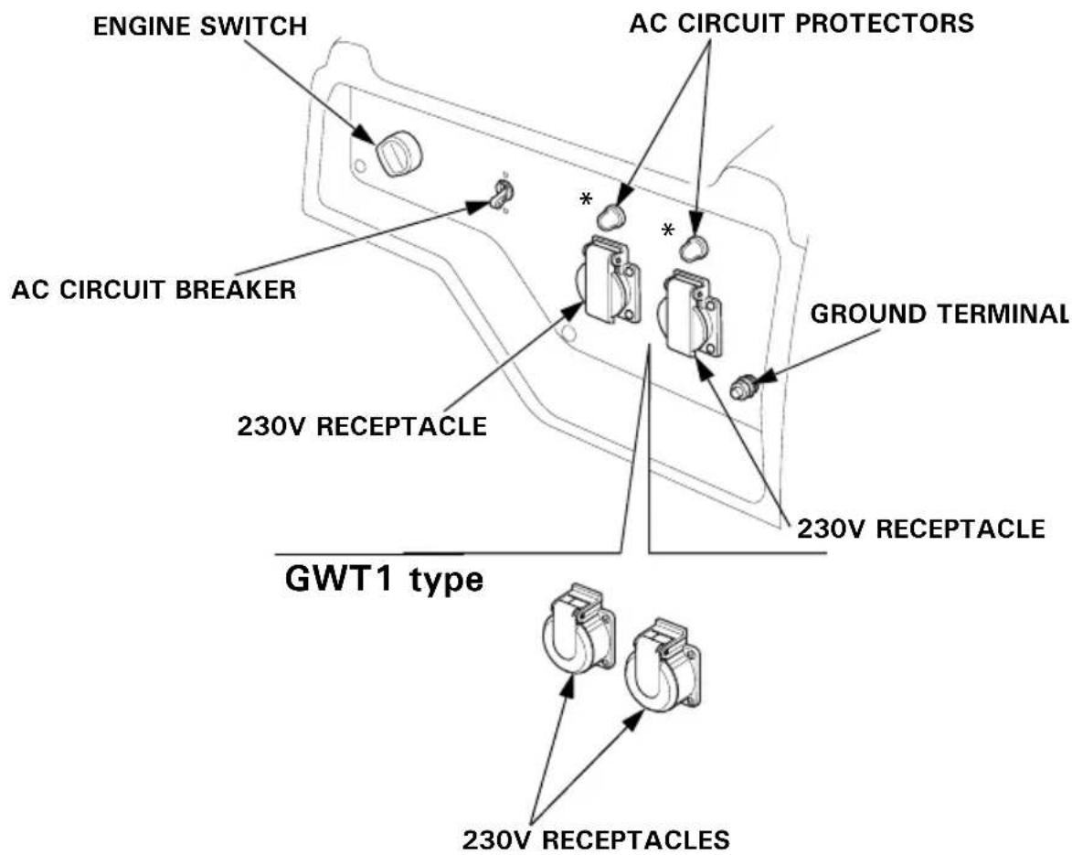
EG4500CL, EG5500CL: GWT1 type
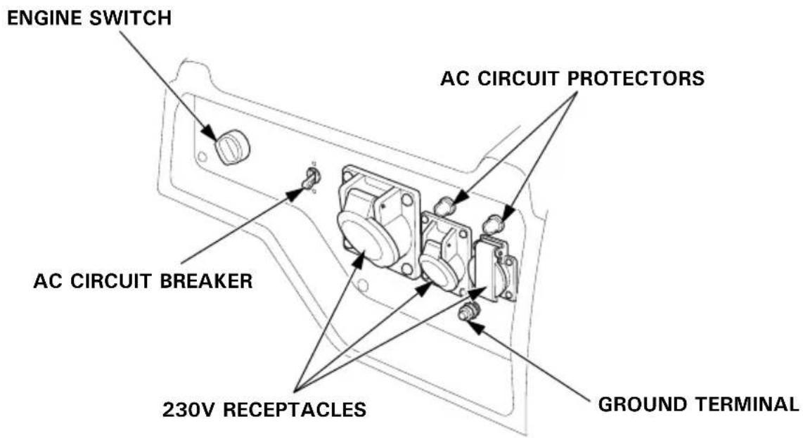
EG4500CL, EG5500CL: FT type
EG4500CL, EG5500CL: ITT type
CAUTION:
Be sure to check the generator on a level surface with the engine stopped.
- Check the engine oil level before each use.
CAUTION:
Using non detergent oil or 2-stroke engine oil could shorten the engine's service life.
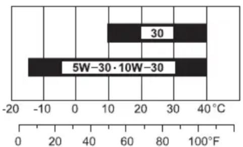
Recommended oil:
Use 4-stroke motor oil that meets or exceeds the requirements for API service category SE or later (or equivalent). Always check the API service label on the oil container to be sure it includes the letters SE or later (or equivalent).
Read the instruction on the oil container before use.
bar
| Category | Value | |---|---| | 30 | 30 | | 5W-30·10W-30 | 5W-30·10W-30 |AMBIENT TEMPERATURE
SAE 10W-30 is recommended for general, all-temperature use. Other viscosities shown in the chart may be used when the average temperature in your area is within the indicated range.
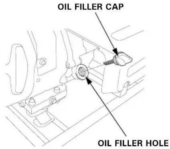
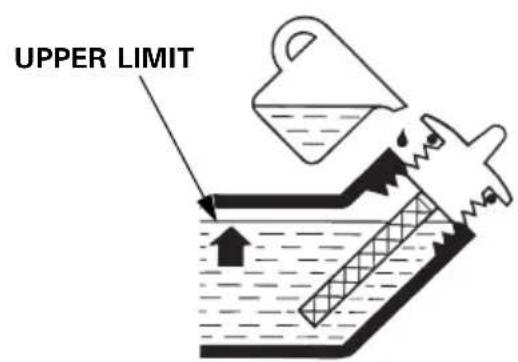
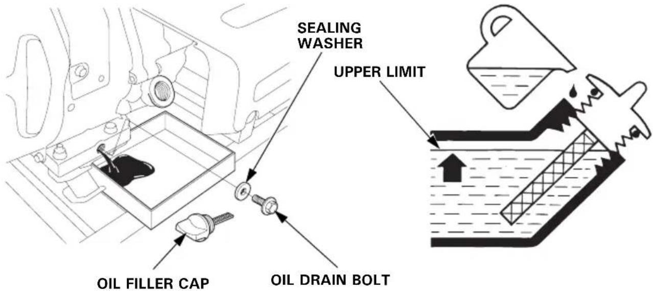
a. Remove the oil filler cap.
b. Check the oil level. If it is below the upper limit, fill with the recommended oil to the upper limit.
c. Reinstall the oil filler cap securely.
CAUTION:
Running the engine with insufficient oil can cause serious engine damage.
NOTE:
The Oil Alert system will automatically stop the engine before the oil level falls below the safe limit. However, to avoid the inconvenience of an unexpected shutdown, it is still advisable to visually inspect the oil level regularly.
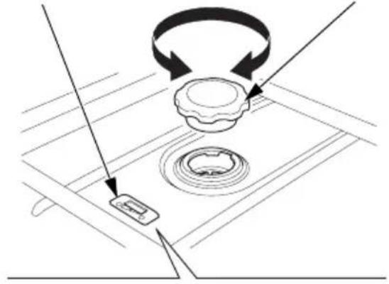
2. Check the fuel level.
Check the fuel gauge. If the fuel level is low, refuel the fuel tank until the level as specified.
After refueling, tighten the fuel tank cap securely.
Use automotive unleaded gasoline with a Research Octane Number of 91 or higher (a Pump Octane Number of 86 or higher).
Never use stale or contaminated gasoline or an oil/gasoline mixture.
Avoid getting dirt or water in the fuel tank.
▲WARNING
- Gasoline is extremely flammable and is explosive under certain conditions.
- Refuel in a well ventilated area with the engine stopped. Do not smoke or allow flames or sparks in the area where the engine is refueled or where gasoline is stored.
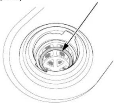
- Do not overfill the fuel tank (there should be no fuel above the upper level mark (red) on the fuel strainer). After refueling, make sure the fuel tank cap is closed properly and securely.
- Be careful not to spill fuel when refueling. Spilled fuel or fuel vapor may ignite. If any fuel is spilled, make sure the area is dry before starting the engine.
- Avoid repeated or prolonged contact with skin or breathing of vapor. KEEP OUT OF REACH OF CHILDREN.
FUEL GAUGE FUEL TANK CAP UPPER LEVEL MARK (RED)
natural_image
Diagram showing a mechanical assembly with rotating components and directional arrows (no text or symbols)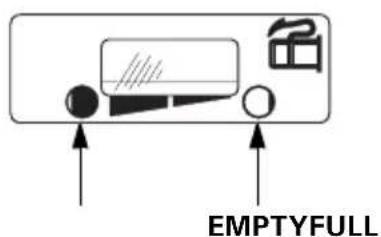
natural_image
Diagram of a car wheel with concentric rings and a pointer indicating the center (no text or labels)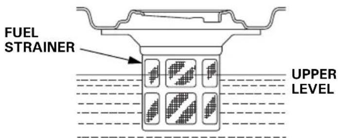
NOTE:
Gasoline spoils very quickly depending on factors such as light exposure, temperature and time.
In worst cases, gasoline can be contaminated within 30 days.
Using contaminated gasoline can seriously damage the engine (caburetor clogged, valve stuck).
Such damage due to spoiled fuel is disallowed from coverage by the warranty.
To avoid this please strictly follow these recommendations:
- Only use specified gasoline (see page 19).
- Use fresh and clean gasoline.
- To slow deterioration, keep gasoline in a certified fuel container.
- If long storage (more than 30 days) is foreseen, drain fuel tank and carburetor (see page 45).
Gasolines Containing Alcohol
If you decide to use a gasoline containing alcohol (gasohol), be sure its octane rating is at least as high as that recommended by Honda.
There are two types of “gasohol”: one containing ethanol, and the other containing methanol.
Do not use gasohol that contains more than 10% ethanol.
Do not use gasoline containing more than 5% methanol (methyl or wood alcohol) and that does not also contain co-solvents and corrosion inhibitors for methanol.
NOTE:
- Fuel system damage or engine performance problems resulting from the use of gasoline that contains more alcohol than recommended is not covered under the warranty.
- Before buying gasoline from an unfamiliar station, first determine if the gasoline contains alcohol, if it does, find out the type and percentage of alcohol used.
If you notice any undesirable operating symptoms while using a particular gasoline. Switch to a gasoline that you know contains less than the recommended amount of alcohol.
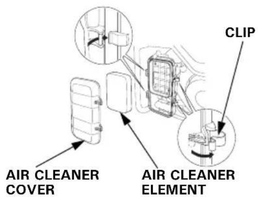
3. Check the air cleaner.
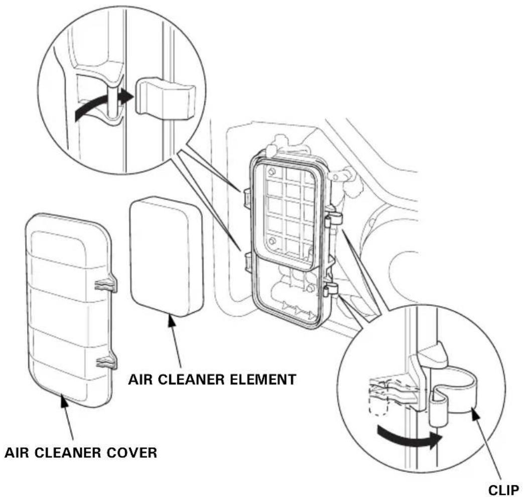
Check the air cleaner element to be sure it is clean and in good condition.
Unsnap the two air cleaner cover clips, remove the air cleaner cover, and remove the air cleaner element.
Clean or replace the air cleaner element if necessary (see page 38).
CAUTION:
Never run the engine without the air cleaner element. Rapid engine wear will result from contaminants, such as dust and dirt, being drawn through the carburetor, into the engine.
5. STARTING THE ENGINE
CAUTION:
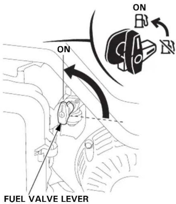
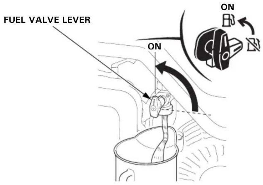
When starting the generator after adding fuel for the first time, after long-term storage, or after running out of fuel, turn the fuel valve lever to the ON position, then wait for 10 to 20 seconds before starting the engine.
Before starting the engine disconnect any load from the AC receptacle.
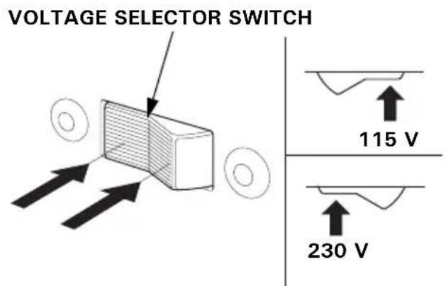
1.BT type only
Set the Voltage Selector Switch to match the voltage requirements for the application.

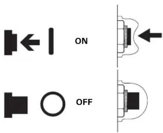
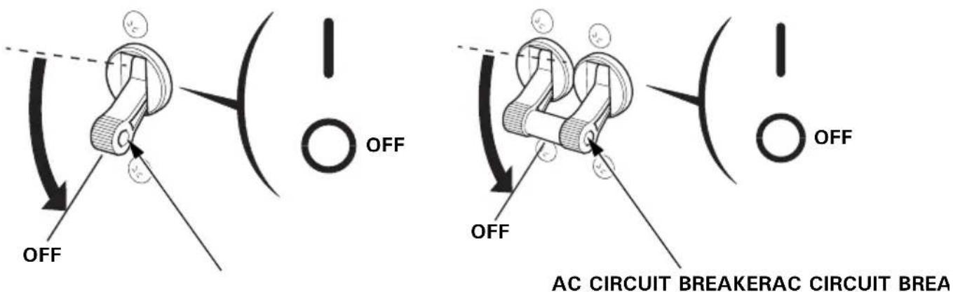
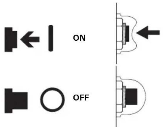
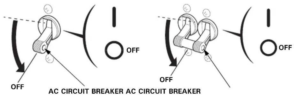
- Make sure that the AC circuit breaker is in the OFF position. The generator may be hard to start if a load is connected.
FT, GT, GWT, GWT1, ITT, CLT types BT type
- Turn the fuel valve lever to the ON position.
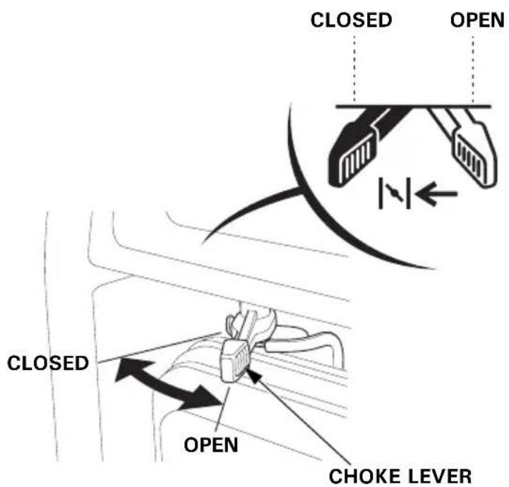
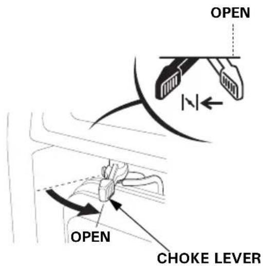
- Move the choke lever to the CLOSED position to start a cold engine. Move the choke lever to the OPEN position as the engine warms up.
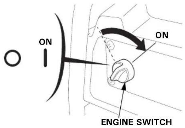
- Turn the engine switch to the ON position.
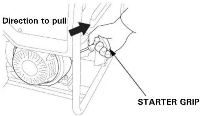
- Pull the starter grip lightly until you feel resistance, then pull the starter grip briskly toward in the direction of the arrow as shown below.
CAUTION:
- The starter grip can be drawn back very quickly before you release it. This may pull your hand forcefully toward the engine and cause an injury.
- Do not allow the starter grip to snap back. Return it slowly by hand.
- Do not let the starter rope rub against the generator body, or the rope will wear out prematurely.
- Move the choke lever to the OPEN position as the engine warms up.
• High altitude operation
At high altitude, the standard carburetor air-fuel mixture will be excessively rich. Performance will decrease, and fuel consumption will increase.
High altitude performance can be improved by specific modifications to the carburetor. If you always operate the generator at altitudes higher than 1,500 meters (5,000 feet) above sea level, have your servicing dealer perform these carburetor modifications.
Even with suitable carburetor jetting, engine horsepower will decrease approximately 3.5% for each 300 meter (1,000 foot) increase in altitude. The affect of altitude on the horsepower will be greater than this if no carburetor modification is made.
CAUTION:
Operation of the generator at an altitude lower than the carburetor is jetted for may result in reduced performance, overheating, and serious engine damage caused by an excessively lean air/fuel mixture.
6. GENERATOR USE
The generator produces enough electric power to cause a serious shock or electrocution if misused.
Be sure to ground the generator when the connected appliance is grounded.
To ground the terminal of the generator, use a copper wire with same or larger diameter than the cord of the connected appliance.
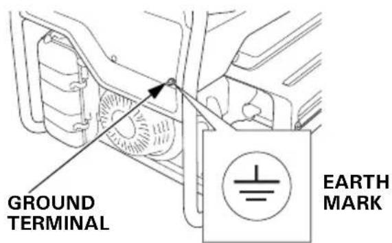
Use extension cord set with ground conductor when connecting an appliance with ground conductor.
To identify the Ground pin in the plug, see RECEPTACLE page 56.
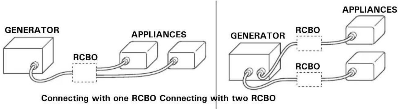
Connect a RCBO (Residual current circuit breaker with overload protection) of 30 mA ground fault detection and cut-off of less than 0.4 seconds at more than 30 A of output current, if you are using two or more appliance.
Follow the instructions provided by each RCBO manufacturer before use.
▲WARNING
Improper connections to a building's electrical system can allow current from the generator to backfeed into the utility lines.
Such backfeed may electrocute utility company workers or others who contact the lines during a power outage, and the generator may explode, burn, or cause fires when utility power is restored.
Consult the utility company or a qualified electrician prior to making any power connections.
CAUTION:
- Do not exceed the current limit specified for any one receptacle.
- Do not modify or use the generator for other purposes than it is intended for. Also observe the following when using the generator.
- Do not connect an extension to the exhaust pipe.
- When an extension cable is required, be sure to use a tough rubber sheathed flexible cable (IEC 245 or equivalent).
- Limit length of extension cables; 60 m (200 feet) for cables of 1.5 mm ^2 (0.0023 in ^2 ) and 100 m (330 feet) for cables of 2.5 mm ^2 (0.0039 in ^2 ). Long extension cables will lower usable power due to resistance in the extension cable.
- Keep the generator away from other electric cables or wires such as commercial power supply lines.
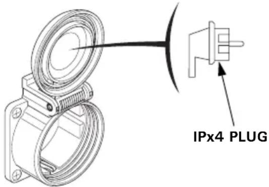
▲WARNING
GWT1 Type
When connecting an angled plug, be sure to use only a IPx4 plug.
NOTE:
- Most appliance motors require more than their rated wattage for startup. Make sure the electrical rating of the tool or appliance does not exceed the maximum power rating of the generator.
Maximum power is:
EG3600CL: 3.6 kVA (BT, FT, GT, GWT, GWT1, ITT, CLT types)
EG4500CL: 3.68/4.5 kVA (BT type)
4.5 kVA (FT, GT, GWT, GWT1, ITT, CLT types)
EG5500CL: 3.68/5.5 kVA (BT type)
5.5 kVA (FT, GT, GWT, GWT1, ITT, CLT types)
- For continuous operation, do not exceed the rated power.
Rated power is:
EG3600CL: 3.2 kVA (BT, FT, GT, GWT, GWT1, ITT, CLT types)
EG4500CL: 3.68/4.0 kVA (BT type)
4.0 kVA (FT, GT, GWT, GWT1, ITT, CLT types)
EG5500CL: 3.68/5.0 kVA (BT type)
5.0 kVA (FT, GT, GWT, GWT1, ITT, CLT types)
- In either case, the total power requirements (VA) of all appliances connected must be considered.
AC Applications
CAUTION:
- Substantial overloading will switch off the AC circuit breaker. Marginal overloading may not switch off the AC circuit breaker, but it will shorten the service life of the generator.
- Be sure that all appliances are in good working order before connecting them to the generator. Electrical equipment (including lines and plug connections) should not be defective. If an appliance begins to operate abnormally, becomes sluggish, or stops suddenly, turn off the generator engine switch immediately. Then disconnect the appliance, and examine it for signs of malfunction.
1.BT type only Set the Voltage Selector Switch to match the voltage requirements for the application.
-
Start the engine (see page 22).
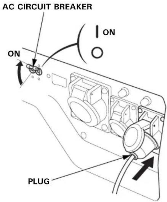
-
Switch the AC circuit breaker ON.
-
Confirm that the appliance to be used is switched off, and plug in the appliance.
Most motorized appliances require more than their rated power for startup.
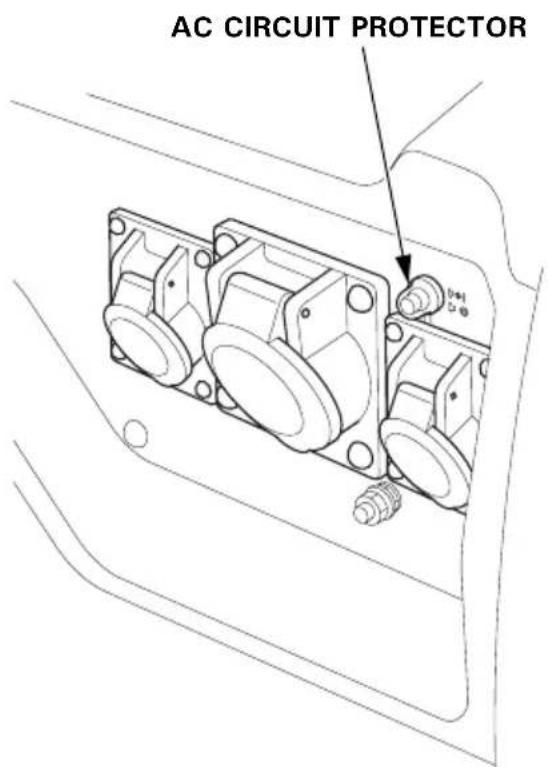
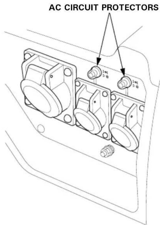
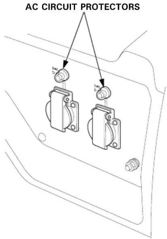
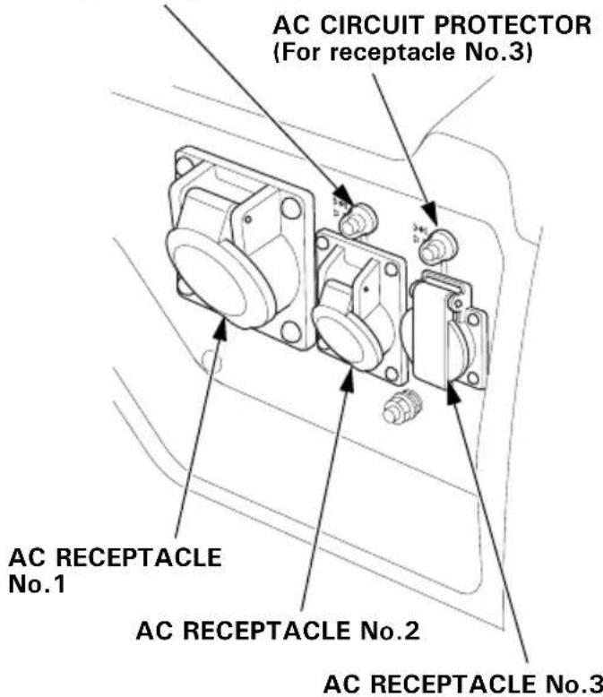
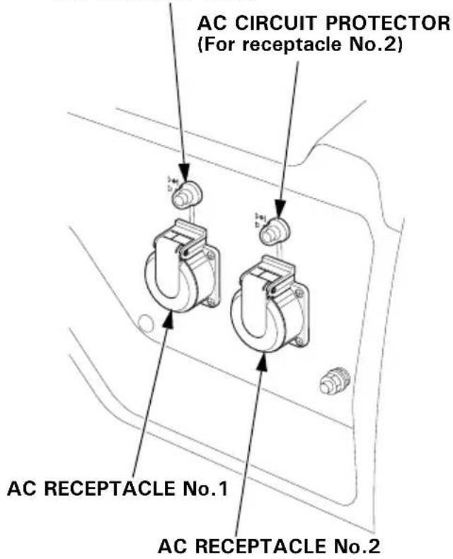
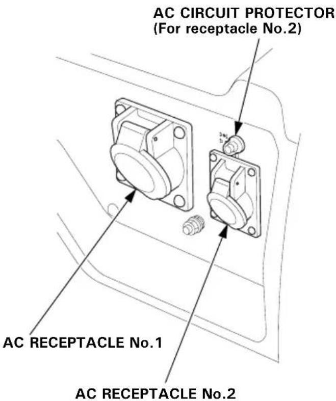
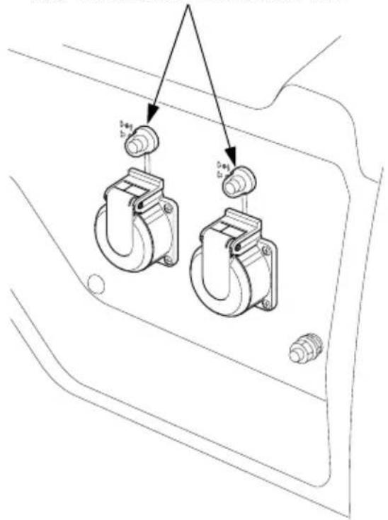
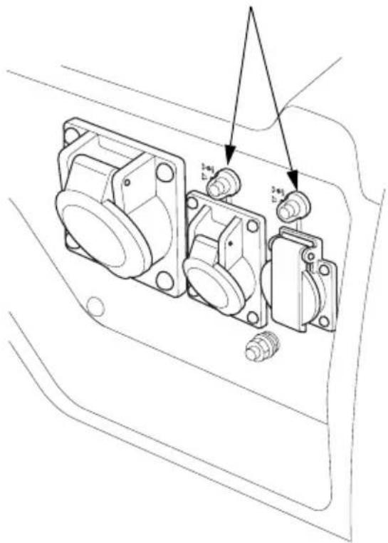
AC Circuit Protectors
The AC circuit protectors will automatically switch OFF (push button comes out) if there is a short circuit or a significant overload of the generator at receptacle.
If an AC circuit protector switches OFF automatically, check that the appliance is working properly and does not exceed the rated load capacity of the circuit before resetting the AC circuit protector ON (pushing the push button in).
EG4500CL, EG5500CL: BT type
EG3600CL: BT type
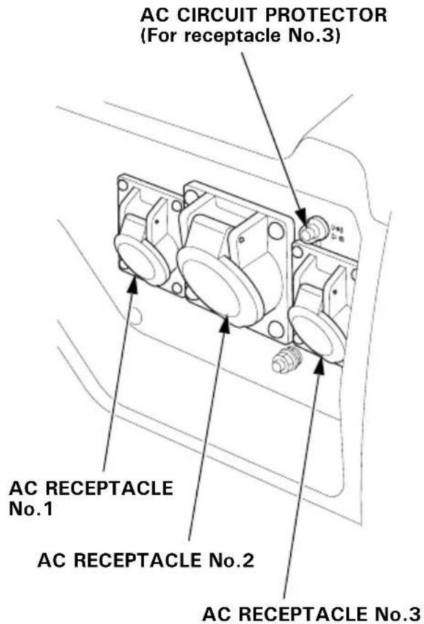

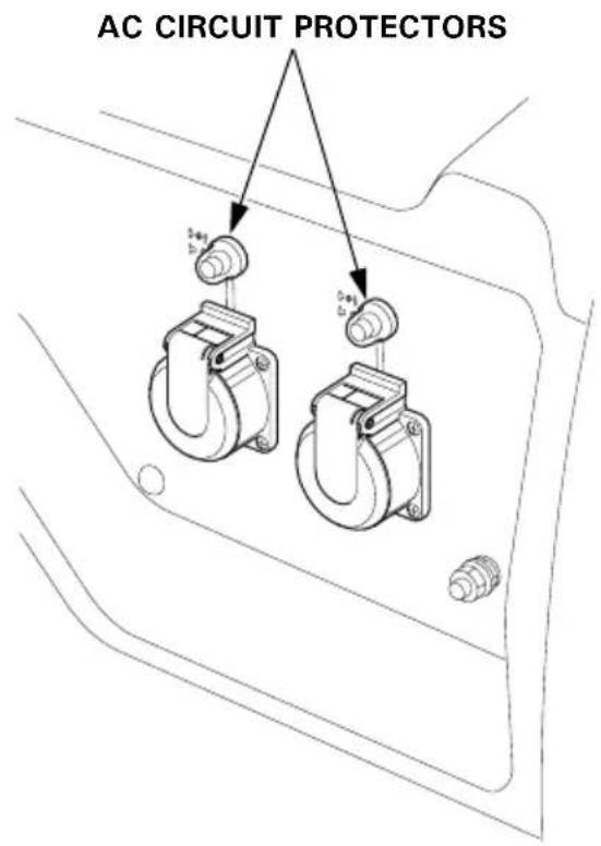
EG4500CL, EG5500CL: GT, GWT, CLT types
AC CIRCUIT PROTECTOR
(For receptacle No.1)
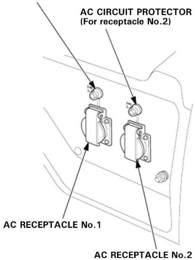
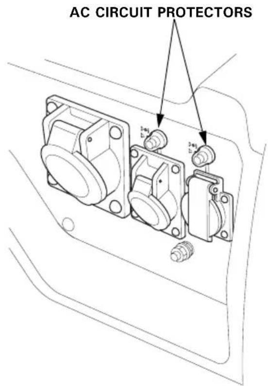
EG4500CL, EG5500CL: FT type
AC CIRCUIT PROTECTOR
(For receptacle No.2)
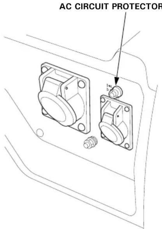
EG4500CL, EG5500CL: GWT1 type
AC CIRCUIT PROTECTOR
(For receptacle No.1)
EG4500CL, EG5500CL: ITT type
Oil Alert System
The Oil Alert system is designed to prevent engine damage caused by an insufficient amount of oil in the crankcase. Before the oil level in the crankcase falls below a safe limit, the Oil Alert system will automatically shut down the engine (the engine switch will remain in the ON position).
If the engine stops and will not restart, check the engine oil level (see page 18) before troubleshooting in other areas.
Automatic Engine Stop Function
Oil Alert Function
During operation, the engine will automatically stop if there is not enough oil in the tank. Moreover, if the generator is on a slope, the oil alert function may operate and stop the engine.
Overspeed Detection Function
To protect the engine from exceeding the engine load, the engine will automatically stop if the engine speed becomes abnormal.
Abnormal Voltage Detection Function
The engine will automatically stop during generation when it detects abnormal voltage.
If the engine stops, inspect the amount of engine oil, and a while, then try to restart the engine. When the engine will not start at all, take your generator to the dealer.
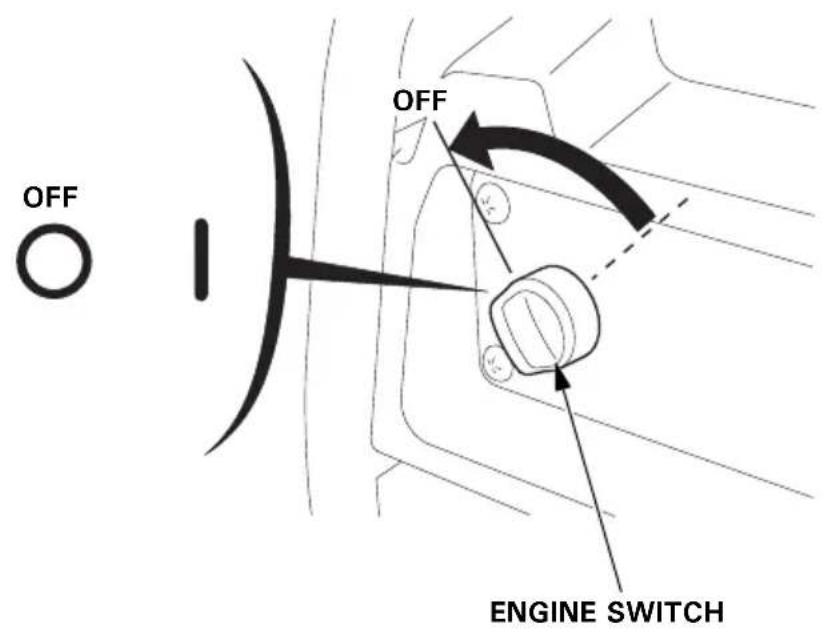
To stop the engine in an emergency, turn the engine switch to the OFF position.
IN NORMAL USE:
- Switch off the connected equipment and pull off the inserted plug.
- Turn the AC circuit breaker to the OFF position.
FT, GT, GWT, GWT1, ITT, CLT types BT type
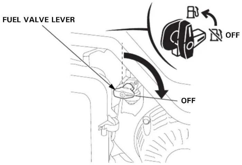
- Turn the engine switch to the OFF position.
- Turn the fuel valve lever to the OFF position.
The purpose of the maintenance and adjustment schedule is to keep the generator in the best operating condition.
Inspect or service as scheduled in the table below.
▲WARNING
Make sure the engine is off before you begin any maintenance or repairs. This will eliminate several potential hazards:
- Carbon monoxide poisoning from engine exhaust. Be sure there is adequate ventilation whenever you operate the engine.
- Burns from hot parts. Let the engine and exhaust system cool before touching.
- Injury from moving parts. Do not run the engine unless instructed to do so.
The muffler becomes very hot during operation and remains hot for a while after stopping the engine. Be careful not to touch the muffler while it is hot. Let the engine cool before maintenance.
CAUTION:
Use Honda Genuine parts or their equivalent. The use of replacement parts which are not of equivalent quality may damage the generator.
Maintenance Schedule
| REGULAR SERVICE PERIOD (1)Perform at every indicated month or operating hour interval, whichever comes first. | Each use | First month or 20 Hrs. | Every 3 months or 50 Hrs. | Every 6 months or 100 Hrs. | Every year or 300 Hrs. | Page | |
| ITEM | |||||||
| Engine oil Check Level o 18 | |||||||
| Change o o 37 | |||||||
| Air cleaner Check o 21 | |||||||
| Clean o (2) 38 | |||||||
| Sediment cup Clean o 39 | |||||||
| Spark plug Check-adjust o 40 | |||||||
| Replace o | 40 | ||||||
| Spark arrester | Clean | o | 42 | ||||
| Valve clearance | Check-adjust | o (3) | - | ||||
| Combustion chamber | Clean | After every 1000 Hrs. (3) | - | ||||
| Fuel tank and filter | Clean | o (3) | - | ||||
| Fuel tube | Check | Every 2 years (Replace if necessary) (3) | - | ||||
(1) For commercial use, log hours of operation to determine proper maintenance intervals.
(2) Service more frequently when used in dusty areas.
(3) These items should be serviced by your servicing dealer, unless you have the proper tools and are mechanically proficient. Refer to the Honda shop manual for service procedures.
Tools
A box wrench and wrench handle are supplied with the generator. Use the supplied tools to perform maintenance tasks. Using an incorrect tool may damage the generator.
1.CHANGING OIL
Drain the oil while the engine is still warm to assure rapid and complete draining.
- Remove the oil drain bolt and sealing washer, remove the oil filler cap, and drain the oil.
- Reinstall the drain bolt and new sealing washer. Tighten the bolt securely.
- Refill with the recommended oil (see page 17) and check the oil level.
Wash your hands with soap and water after handling used oil.
NOTE:
Please dispose of used motor oil in a manner that is compatible with the environment. We suggest you take it in a sealed container to your local service station for reclamation. Do not throw it in the trash or pour it on the ground.
2.AIR CLEANER SERVICE
A dirty air cleaner will restrict air flow to the carburetor. To prevent carburetor malfunction, service the air cleaner regularly. Service more frequently when operating the generator in extremely dusty areas.
▲WARNING
Do not use gasoline or low flash point solvents for cleaning. They are flammable and explosive under certain conditions.
CAUTION:
Never run the engine without the air cleaner element. Rapid engine wear will result.
- Unsnap the two air cleaner cover clips, remove the air cleaner cover, and remove the air cleaner element.
- Clean in warm soapy water, rinse and allow to dry to thoroughly. Or clean in high flash point solvent and allow to dry. Dip the element in clean engine oil and squeeze out all the excess. The engine will smoke during initial startup if too much oil is left in the foam.
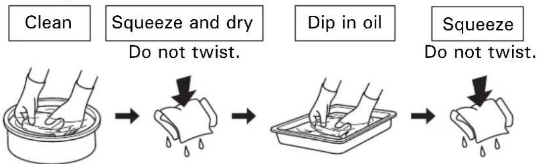
flowchart
graph LR
    A["Clean"] --> B["Squeeze and dry\nDo not twist."]
    B --> C["Dip in oil"]
    C --> D["Squeeze\nDo not twist."]
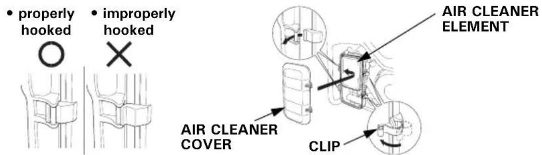
- Reinstall the air cleaner element and the cover.
3.FUEL SEDIMENT CUP SERVICE
▲WARNING
Gasoline is extremely flammable and is explosive under certain conditions. Do not smoke or allow flames or sparks in the area.
The sediment cup prevents dirt or water that may be in the fuel tank from entering the carburetor. If the engine has not been run for a long time, the sediment cup should be cleaned.
- Turn the engine switch to the OFF position.
- Turn the fuel valve lever to the OFF position. Remove the sediment cup and O-ring.
- Clean the sediment cup in nonflammable or high flash point solvent.
- Reinstall the new O-ring and sediment cup.
- Turn the fuel valve lever to the ON position and check for leaks.
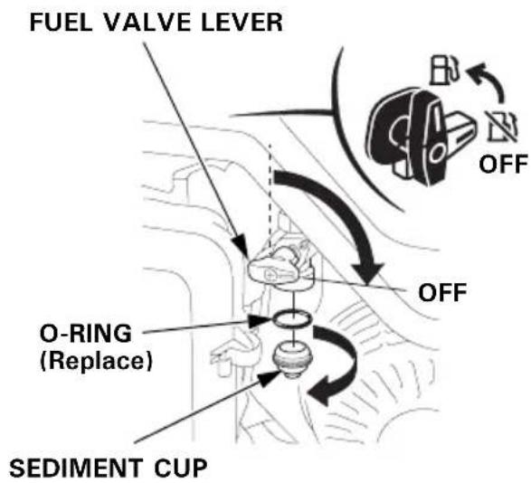
⚠ WARNING
After installing the sediment cup, be sure to tighten it securely. Check for fuel leaks and make sure the area is dry before starting the engine.
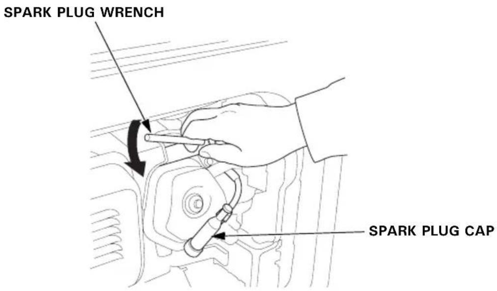
4. SPARK PLUG SERVICE
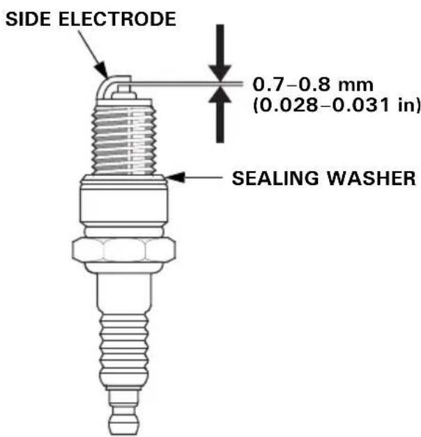
Recommended spark plug: BPR5ES (NGK)
To ensure proper engine operation, the spark plug must be properly gapped and free of deposits.
CAUTION:
If the engine has been running, the muffler will be very hot. Be careful not to touch the muffler.
- Remove the spark plug cap.
- Clean any dirt from around the spark plug base.
- Use a spark plug wrench to remove the spark plug.
-
Visually inspect the spark plug. Discard it if the insulator is cracked, chipped, or fouled. Clean the spark plug with a wire brush if it is to be reused.
-
Measure the plug gap with a feeler gauge.
Correct as necessary by carefully bending the side electrode.
The gap should be:
0.7–0.8 mm (0.028–0.031 in)
-
Make sure that the sealing washer is in good condition, and thread the spark plug in by hand to prevent cross-threading.
-
After the spark plug is seated, tighten with a spark plug wrench to compress the washer.
NOTE:
If installing a new spark plug, tighten 1/2 turn after the spark plug seats to compress the washer. If reinstalling a used spark plug, tighten 1/8 to 1/4 turn after the spark plug seats.
- Reinstall the spark plug cap on the spark plug securely.
CAUTION:
- The spark plug must be securely tightened. An improperly tightened plug can become very hot and possibly damage the generator.
- Never use a spark plug with an improper heat range.
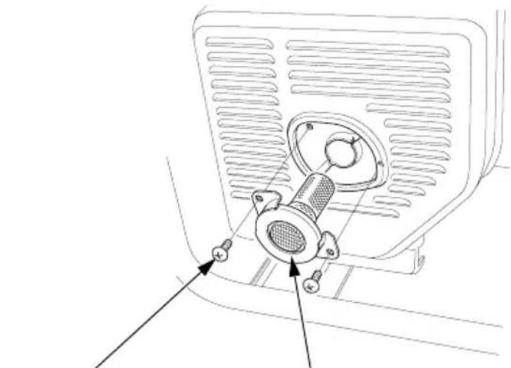
5. SPARK ARRESTER CLEANING
▲WARNING
If the generator has been running, the muffler will be very hot. Allow it to cool before proceeding.
- Remove the two 5 mm screws, and remove the spark arrester.
natural_image
Technical line drawing of a mechanical component with mounting holes and a central hub (no text or symbols)5 mm SCREWS SPARK ARRESTER
- Use a brush to remove carbon deposits from the spark arrester screen. Inspect the screen for breaks or tears and replace it if necessary.
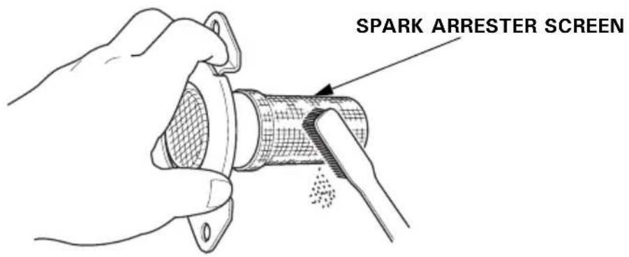
- Install the spark arrester in the reverse order of removal.
Transporting
To prevent fuel spillage when transporting or during temporary storage, the generator should be secured upright in its normal operating position, with the engine switch OFF.
The fuel valve lever should be turned OFF.
▲WARNING
- When transporting the generator:
- Do not overfill the tank. - Do not operate the generator while it is on a vehicle. Take the generator off the vehicle and use it in a well ventilated place.
- Avoid a place exposed to direct sunlight when putting the generator on a vehicle. If the generator is left in an enclosed vehicle for many hours, high temperature inside the vehicle could cause fuel to vaporize resulting in a possible explosion.
- Do not drive on a rough road for an extended period with the generator on board. If you must transport the generator on a rough road, drain the fuel from the generator beforehand.
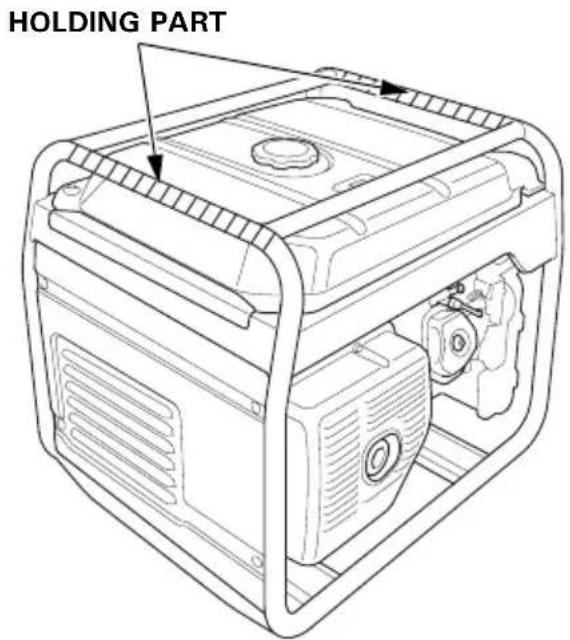
NOTE:
To lift up the generator, hold the holding part (shaded areas in the figure below) with your assistants.
According to EUROPEAN STANDARD EN 12601: 2010
Carrying the generating set is considered that a 140 kg set should be provided with the means of carrying by 4 persons.
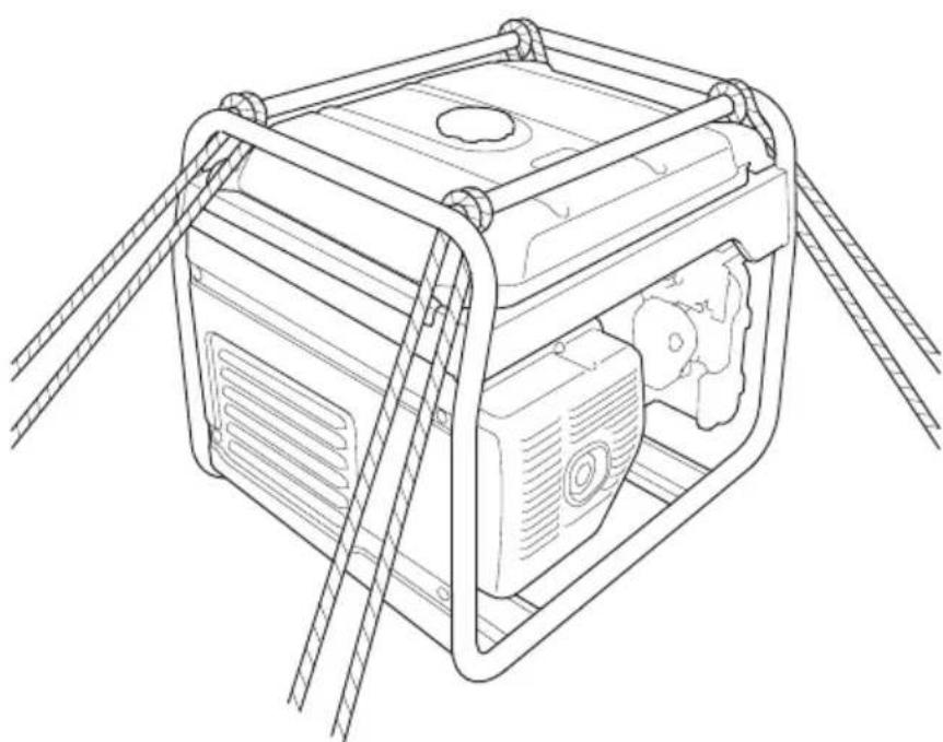
Take care not to drop or strike the generator when transporting. Do not place heavy objects on the generator.
When transporting the generator by loading it on to a vehicle, secure to the generator frame as shown.
natural_image
Line drawing of a mechanical device with attached wiring, no text or symbols presentStorage
- Place a suitable gasoline container below the carburetor, and use a funnel to avoid spilling fuel.
- Remove the drain bolt and sealing washer and drain the gasoline from the carburetor.
▲WARNING
Gasoline is extremely flammable and is explosive under certain conditions. Perform this task in a well ventilated area with the engine stopped. Do not smoke or allow flames or sparks in the area during this procedure.
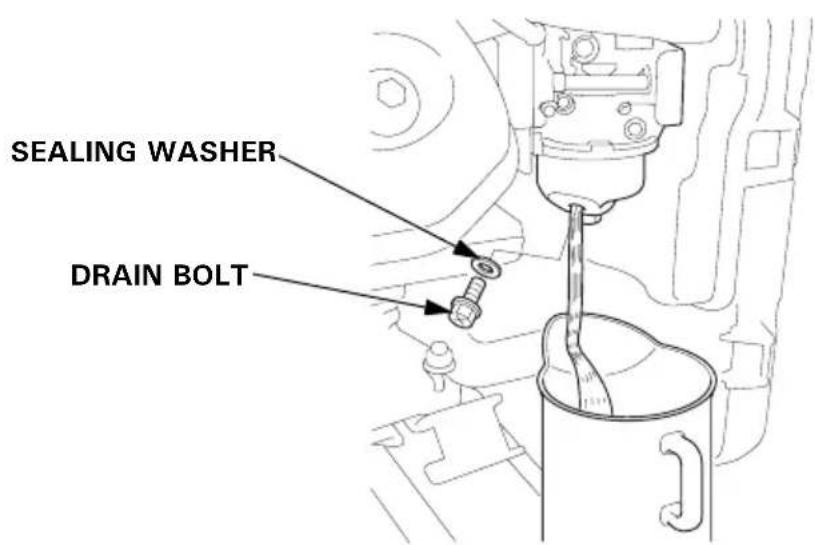
- After all the gasoline has drained into the container, tighten the drain bolt securely.
-
Place a suitable gasoline container below the sediment cup, and use a funnel to avoid spilling gasoline.
-
Remove the sediment cup (see page 39), and then turn the fuel valve lever to the ON position.
-
Allow the gasoline to drain completely, and then install the sediment cup (see page 39).
-
Change the engine oil (refer to page 37).
-
Remove the spark plug, and pour about a tablespoon of clean engine oil into the cylinder. Turn the engine several revolutions slowly with the recoil starter to distribute the oil, then reinstall the spark plug.
-
Slowly pull the starter grip until resistance is felt. At this point, the piston is coming up on its compression stroke and both the intake and exhaust valves are closed. Storing the engine in this position will help to protect it from internal corrosion.
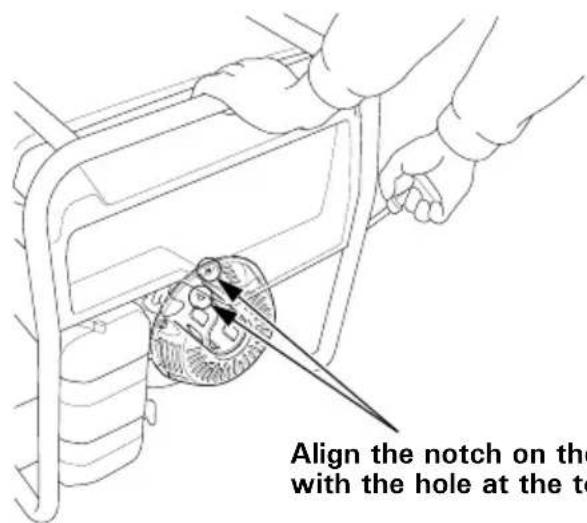
Align the notch on the starter pulley with the hole at the top of recoil starter.
When the engine will not start:

flowchart
graph TD
    A["Is there fuel in the tank?"] -->|YES| B["Is the engine switch ON?"]
    A -->|NO| C["Refill the fuel tank (see page 19)."]
    B -->|YES| D["Is there enough oil in the engine?"]
    B -->|NO| E["Turn the engine switch ON (see page 24)."]
    D -->|YES| F["Is the spark plug in good condition?"]
    D -->|NO| G["Add the recommended oil (see page 17)."]
    F -->|YES| H["Is the fuel reaching the carburetor?"]
    F -->|NO| I["Clean, readjust gap and dry the spark plug. Replace it if necessary (see page 40)."]
    H -->|YES| J["Is there fuel reaching the carburetor?"]
    H -->|NO| K["Clean the fuel sediment cup (see page 39)."]
To check:
1) Turn off the engine switch and remove the drain bolt (see page 45).
2) Turn the fuel valve lever to ON. Fuel should flow from the drain when the fuel valve lever is turned on.
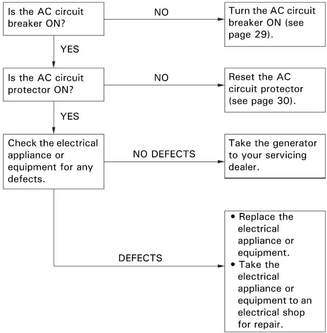
No electricity at the AC receptacles:
flowchart
graph TD
    A["Is the AC circuit breaker ON?"] -->|YES| B["Is the AC circuit protector ON?"]
    A -->|NO| C["Turn the AC circuit breaker ON (see page 29)."]
    B -->|YES| D["Check the electrical appliance or equipment for any defects."]
    B -->|NO| E["Reset the AC circuit protector (see page 30)."]
    D -->|NO DEFECTS| F["Take the generator to your servicing dealer."]
    D -->|DEFECTS| G["Replace the electrical appliance or equipment.<br>Take the electrical appliance or equipment to an electrical shop for repair."]
Dimensions and Weight
| Model EG3600CL | EG4500CL | |
| Type BT, FT, GT, GWT, GWT1, ITT, CLT | ||
| Description code EBGC EBEC | ||
| Length 681 mm (26.8 in) | ||
| Width 530 mm (20.9 in) | ||
| Height 571 mm (22.5 in) | ||
| Dry mass [weight] 68.0 kg (149.9 lbs) 79.5 kg (175.3 lbs) | ||
Engine
| Model GX270 GX390 | ||
| Engine Type 4-stroke, overhead valve, single cylinder | ||
| Displacement[Bore × Stroke] | 270 cm ^3 (16.5 cu-in)77.0 × 58.0 mm(3.03 × 2.28 in) | 389 cm ^3 (23.7 cu-in)88.0 × 64.0 mm(3.46 × 2.52 in) |
| Compression ratio 8.5:1 8.2:1 | ||
| Engine speed | 3,000 rpm | |
| Cooling system | Forced air | |
| Ignition system | CDI magneto ignition | |
| Oil capacity | 1.1 L (1.2 US qt, 1.0 Imp qt) | |
| Fuel tank capacity | 24.0 L (6.34 US gal, 5.28 Imp gal) | |
| Spark plug | BPR5ES (NGK) | |
Generator
| Model EG3600CL | EG4500CL | ||||
| Type | BT | FT, GT, GWT, GWT1, ITT, CLT | BT | FT, GT, GWT, GWT1, ITT, CLT | |
| AC output | Rated voltage | 115 V/230 V | 230 V | 115 V/230 V | 230 V |
| Rated frequency | 50 Hz | ||||
| Rated current | 27.8 A/13.9 A | 13.9 A 32 | 2.0 A/17.4 A | 17.4 A | |
| Rated output 3.2 | kVA | 3.68 kVA/ | 4.0 kVA | 4.0 kVA | |
| Maximum output | 3.6 kVA | 3.68 kVA/4.5 kVA | 4.5 kVA | ||
Specifications may vary according to the types, and are subject to change without notice.
Dimensions and Weight
| Model EG5500CL | |
| Type BT, FT, GT, GWT, GW | T1, ITT, CLT |
| Description code EBBC | |
| Length 681 mm (26.8 in) | |
| Width 530 mm (20.9 in) | |
| Height 571 mm (22.5 in) | |
| Dry mass [weight] 82.5 kg (181.9 lbs) | |
Engine
| Model GX390 | |
| Engine Type 4-stroke, overhead valve, single cylinder | |
| Displacement[Bore × Stroke] | 389 cm ^3 (23.7 cu-in)88.0 × 64.0 mm (3.46 × 2.52 in) |
| Compression ratio 8.2:1 | |
| Engine speed 3,000 rpm | |
| Cooling system Forced air | |
| Ignition system CDI magneto ignition | |
| Oil capacity 1.1 L (1.2 US qt, 1.0 lmp qt) | |
| Fuel tank capacity | 24.0 L (6.34 US gal, 5.28 lmp gal) |
| Spark plug | BPR5ES (NGK) |
Generator
| Model EG5500CL | |||
| Type | BT | FT, GT, GWT, GWT1, ITT, CLT | |
| AC output | Rated voltage | 115 V/230 V | 230 V |
| Rated frequency | 50 Hz | ||
| Rated current | 32.0 A/21.7 A | 21.7 A | |
| Rated output | 3.68 kVA/5.0 kVA | 5.0 kVA | |
| Maximum output | 3.68 kVA/5.5 kVA | 5.5 kVA | |
Specifications may vary according to the types, and are subject to change without notice.
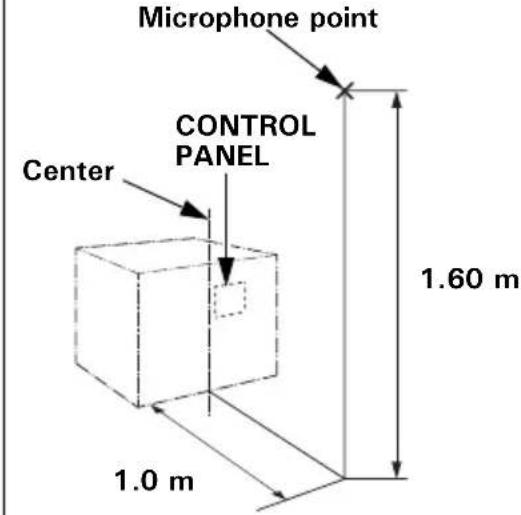
Noise
| Model EG3600CL EG4500CL EG5$00CL | |||
| Type BT, FT, GT, GWT, GWT1, ITT, CLT | |||
| Sound pressure level at the workstation(2006/42/EC) | 79 dB (A) 81 dB (A) 81 dB (A) | ||
 | |||
| Uncertainty | 2 dB (A) | 2 dB (A) | 1 dB (A) |
| Measured sound power level(2000/14/EC, 2005/88/EC) | 94 dB (A) 95 dB (A) 96 dB (A) | ||
| Uncertainty | 2 dB (A) | 2 dB (A) | 1 dB (A) |
| Guaranteed sound power level(2000/14/EC, 2005/88/EC) | 96 dB (A) 97 dB (A) 97 dB (A) | ||
“the figures quoted are emission levels and are not necessarily safe working levels. Whilst there is a correlation between the emission and exposure levels, this cannot be used reliably to determine whether or not further precautions are required. Factors that influence the actual level of exposure of work-force include the characteristics of the work room, the other sources of noise, etc. i.e. the number of machines and other adjacent processes, and the length of time for which an operator is exposed to the noise. Also the permissible exposure level can vary from country. This information, however, will enable the user of the machine to make a better evaluation of the hazard and risk”.
NOTE:
Specifications are subject to change without notice.
OPTIONAL KIT PARTS
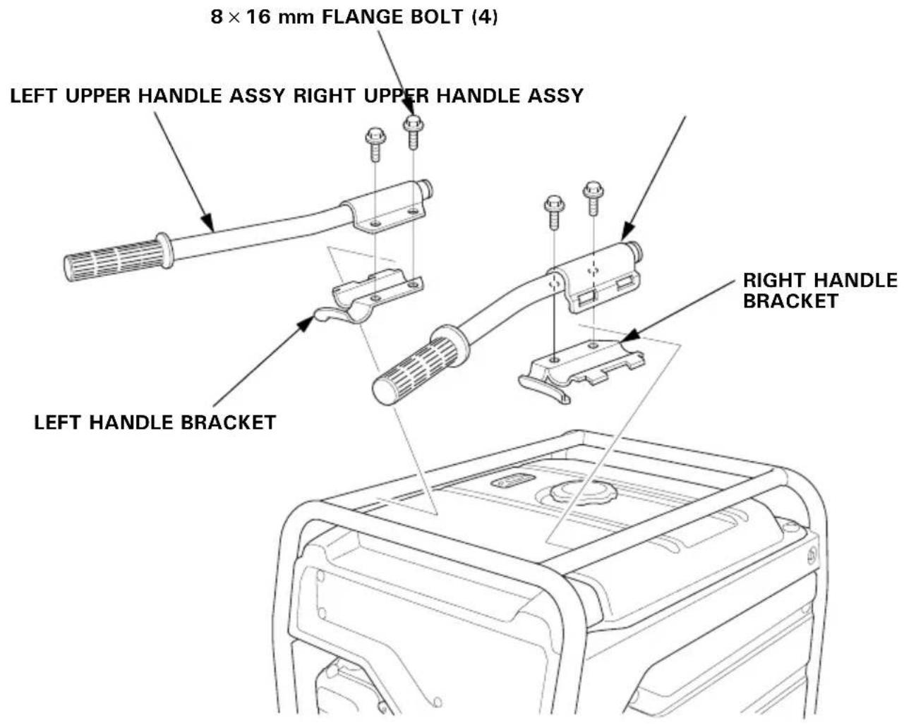
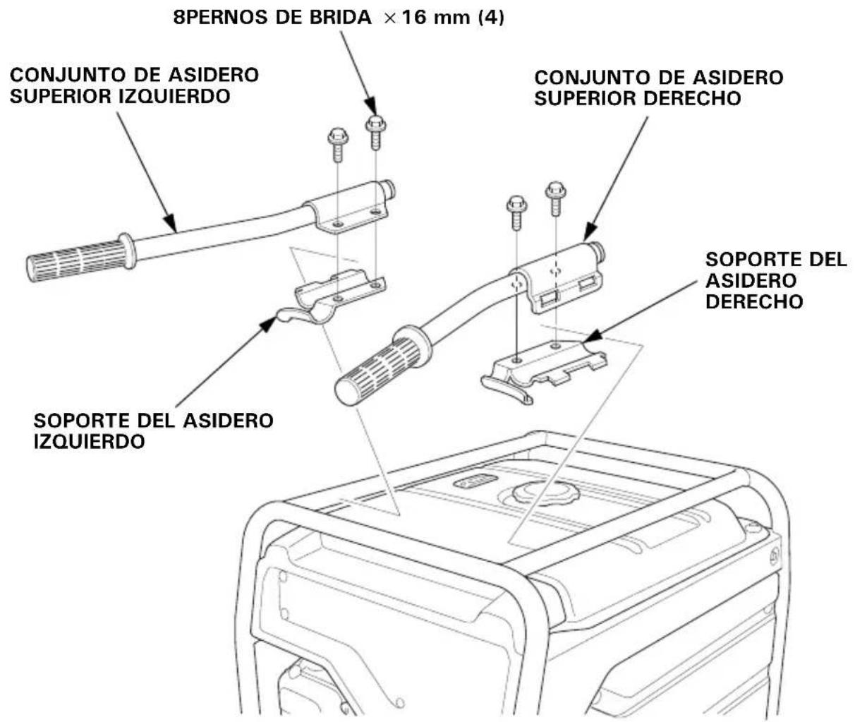
Handle Installation (Two wheel type)
Install the right and left handles on the generator upper frame using the handle brackets and four flange bolts.
TORQUE: 24–29 N·m (2.4–3.0 kgf·m, 17–22 lbf·ft)
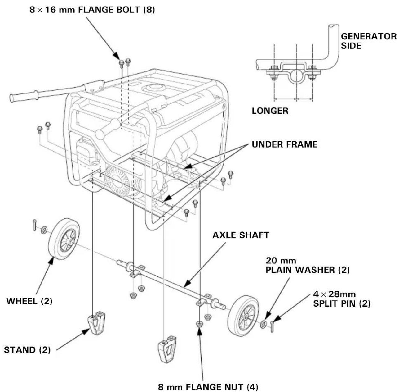
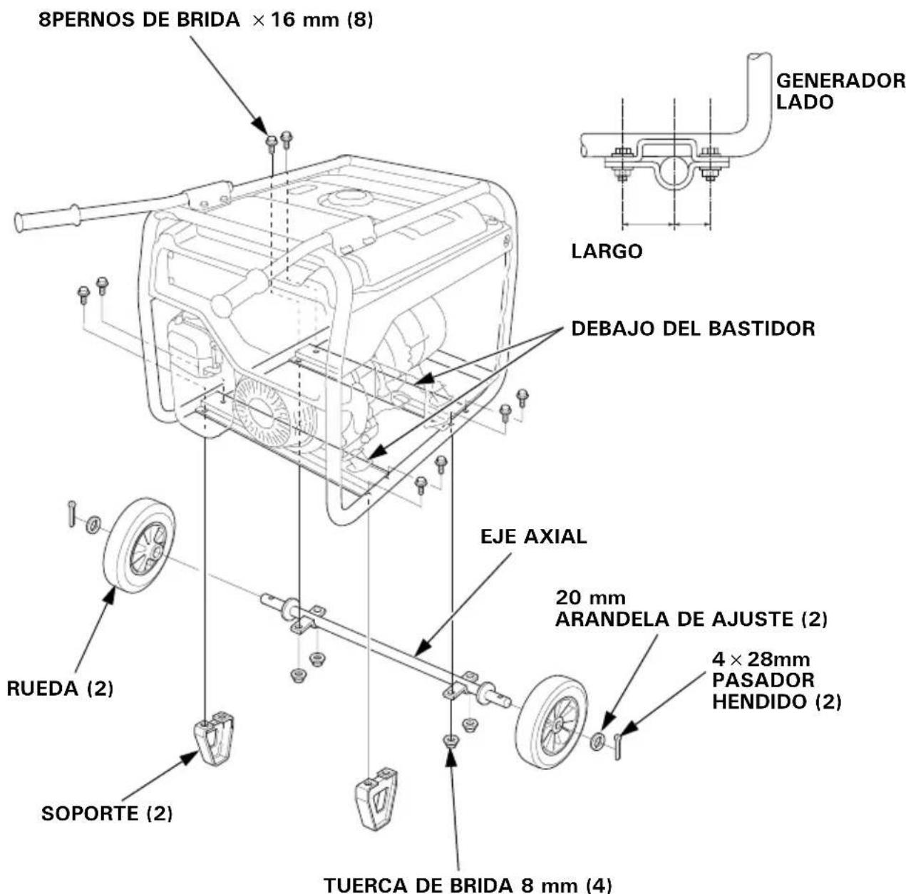
Two Wheel Kit Installation
- Install the two wheels on the axle shaft using the plain washers and split pins.
- Install the axle assembly on the generator using four 8 × 16 mm flange bolts and 8 mm flange nuts.
- Install the two stands on the under frame using four 8 × 16 mm flange bolts.
TORQUE: 24–29 N·m (2.4–3.0 kgf·m, 17–22 lbf·ft)
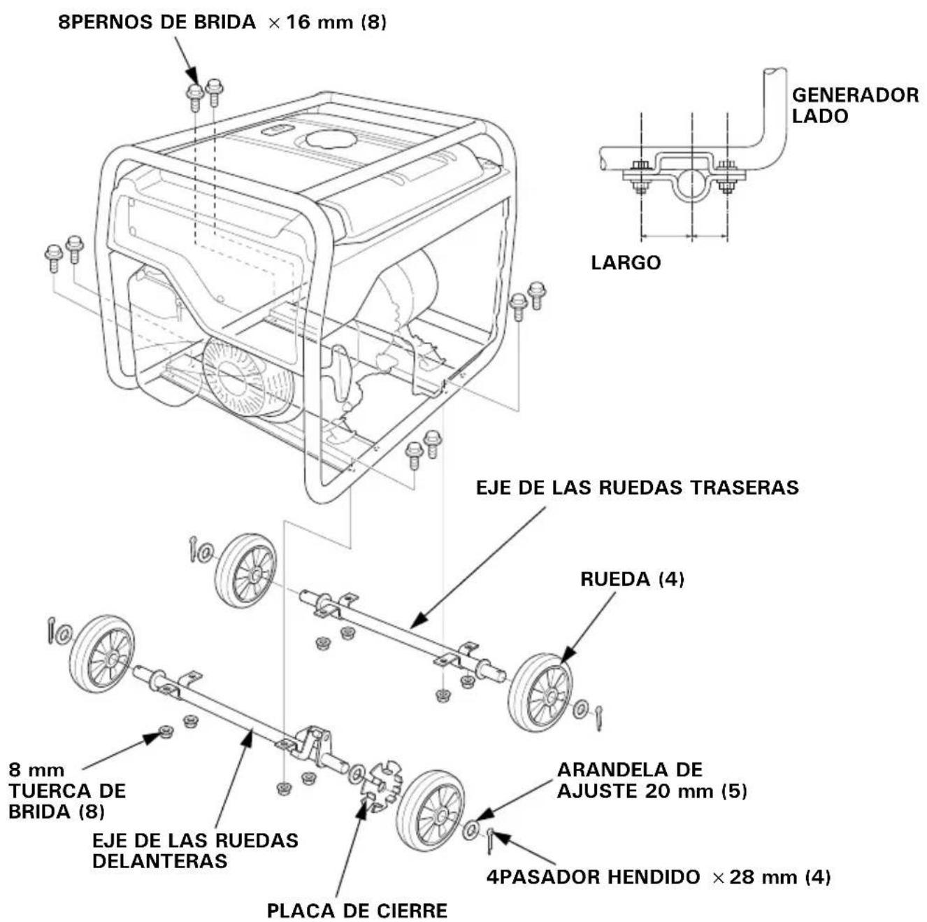
Four Wheel Kit Installation
- Install the lock plate and four wheels on the wheel shaft using the plain washers and split pins.
NOTE:
Install the front wheel shaft on the front side nearest the engine.
- Install the wheel shaft assembly on the generator using eight 8 × 16 mm flange bolts.
TORQUE: 24–29 N·m (2.4–3.0 kgf·m, 17–22 lbf·ft)

INDEX
(See inside back cover)
| Model Type Diagram No. Receptacles | |||
| EG3600CL BT W | -1 *1 | ||
| GT, GWT, GWT1, CLT | W-2 *1 | ||
| FT W-2 *3 | |||
| ITT W-2 *5 | |||
| EG4500CL, EG5500CL | BT W-1 *2 | ||
| GT, GWT, GWT1, CLT | W-2 *2 | ||
| FT W-2 *4 | |||
| ITT W-2 *6 | |||
ABBREVIATIONS WIRE COLOR CODE
| Symbol Part name | |
| AC O | AC Outlet |
| AC CB | AC Circuit Breaker |
| CBB | Control Box Block |
| D-AVR | Digital-Automatic Voltage Regulator |
| D-CDI | Digital-CDI |
| EgB | Engine Block |
| ESw | Engine Switch |
| EX W | Exciter Winding |
| FrB | Frame Block |
| Fu | Fuse |
| FW | Field Winding |
| GeB | Generator Block |
| GND | Ground |
| GT | Ground Terminal |
| IgC | Ignition Coil |
| J/B | Junction Box |
| MW | Main Winding |
| OLSw | Oil Level Switch |
| PoC | Power Coil |
| SP | Spark Plug |
| VSSw | Voltage selector Switch |
| BI | BLACK |
| Y | YELLOW |
| Bu | BLUE |
| G | GREEN |
| R | RED |
| W | WHITE |
| Br | BROWN |
| Lg | LIGHT GREEN |
| Gr | GRAY |
| Lb | LIGHT BLUE |
| O | ORANGE |
| P | PINK |
SWITCH CONNECTIONS
ENGINE SWITCH
| IG DC 12 V | |
| OFF o | |
| ON I o o | — |
RECEPTACLE
| Type Shape Plug | |||
| GT, GWT, ITT, CLT |  |  | GROUND PIN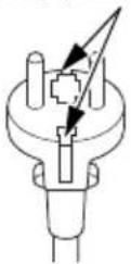 |
| GWT1 |  |  | GROUND PIN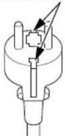 |
| FT | 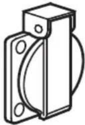 | 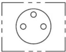 | GROUND PIN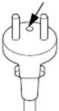 |
| BT, FT, ITT | 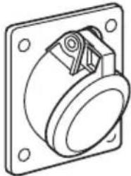 | 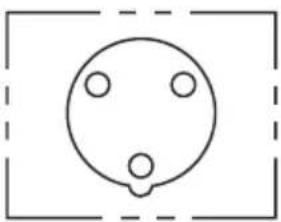 | GROUND PIN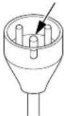 |
| BT | 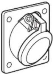 | 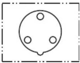 | illustration not available |
Honda EG3600CL·EG4500CL EG5500CL
MANUEL DE L'UTILISATEUR
Notice originale
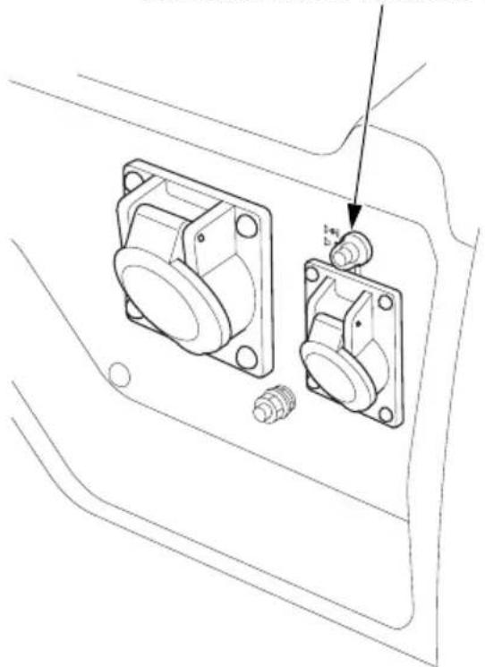
EG4500CL, EG5500CL : Type GWT1
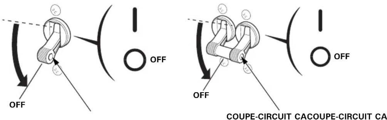
PROTECTEURS DE CIRCUIT CA
EG4500CL, EG5500CL : Type FT
PROTECTEURS DE CIRCUIT CA
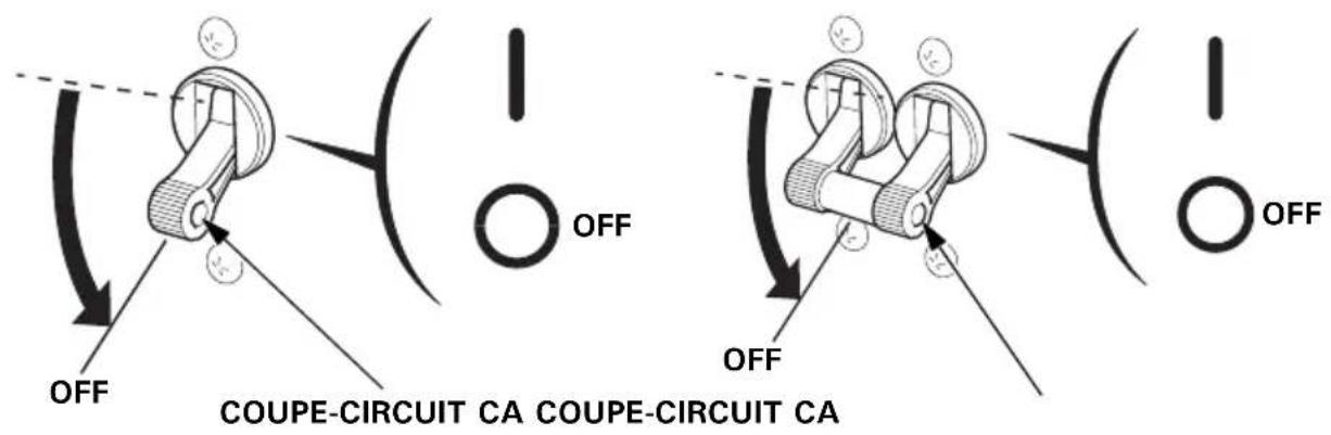
EG4500CL, EG5500CL : Type ITT
PROTECTEUR DE CIRCUIT CA
natural_image
Technical line drawing of two mechanical components with bolts and a pin, no text or symbols presentPRECAUTION :
Types FT, GT, GWT, GWT1, ITT, CLT Type BT
EG4500CL: 3,68/4,0 kVA (BT type) 4,0 kVA (FT, GT, GWT, GWT1, ITT, CLT types)
EG5500CL: 3,68/5,0 kVA (BT type) 5,0 kVA (FT, GT, GWT, GWT1, ITT, CLT types)
Types FT, GT, GWT, GWT1, ITT, CLT Type BT
natural_image
Technical line drawing of a mechanical component with mounting holes and a central hub (no text or symbols)VIS 5 mm PARE-ETINCELLES
natural_image
Line drawing of a portable electric generator unit with coiled cable and mounting bracket (no text or symbols)Remisage
ECOLOGY CONSCIOUS TECHNOLOGY
natural_image
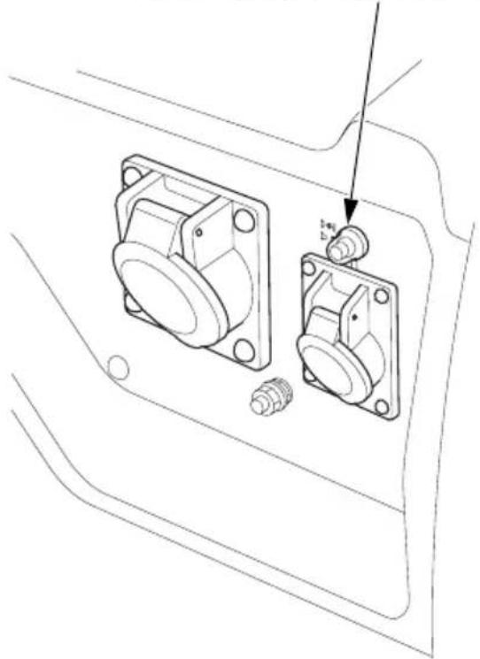
Line drawing of a portable electronic device casing with internal components and a black arrow pointing to a component (no text or symbols)EG4500CL, EG5500CL: Typ GWT1
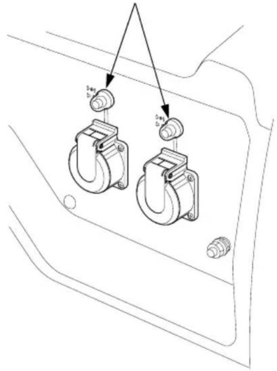
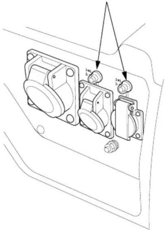
WECHSELSTROM-
SCHALTKREISSCHUTZ

EG4500CL, EG5500CL: Typ FT
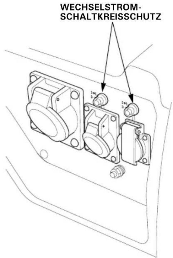
EG4500CL, EG5500CL: Typ ITT
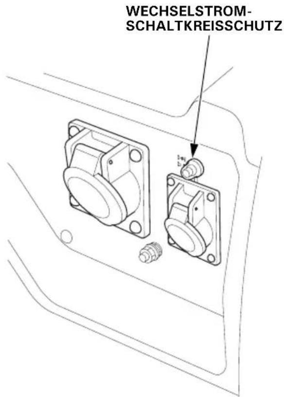
VORSICHT:
4,0 kVA (FT, GT, GWT, GWT1, ITT, CLT types)
EG5500CL: 3,68/5,0 kVA (BT type)
5,0 kVA (FT, GT, GWT, GWT1, ITT, CLT types)
natural_image
Technical line drawing of a mechanical component with two connectors and a central hub (no text or symbols)natural_image
Line drawing of a portable electronic device with attached cables and ventilation slots (no text or symbols)Lagerung
ECOLOGY CONSCIOUS TECHNOLOGY
natural_image
Line drawing of a portable electronic device casing with internal components and a black pointer indicating a component (no text or symbols)EG4500CL, EG5500CL: Tipo GWT1
PROTECTORES DE CIRCUITO CA
EG4500CL, EG5500CL: Tipo FT
PROTECTORES DE CIRCUITO CA
EG4500CL, EG5500CL: Tipo ITT
PROTECTOR DE CIRCUITO CA
natural_image
Technical line drawing of two mechanical components with a bolt and threaded end (no text or symbols)PRECAUCIÓN:
4,0 kVA (FT, GT, GWT, GWT1, ITT, CLT types)
EG5500CL: 3,68/5,0 kVA (BT type)
5,0 kVA (FT, GT, GWT, GWT1, ITT, CLT types)
natural_image
Technical line drawing of a mechanical component with labeled parts (no text or symbols)TORNILLOS DE 5 mm PARACHISPAS
natural_image
Line drawing of a portable electric box with attached wiring, no text or symbols presentAlmacenaje
PAR: 24–29 N·m (2,4–3,0 kgf·m)
PAR: 24–29 N·m (2,4–3,0 kgf·m)
PAR: 24–29 N·m (2,4–3,0 kgf·m)
ÍNDICE
For further information, please contact Honda Customer Information Centre at the following address or telephone number:
ADRESSES DES PRINCIPAUX CONCESSIONNAIRES Honda
BALTIC STATES (Estonia/Latvia/ Lithuania)
Honda Motor Europe Ltd.
Estonian Branch
Tulika 15/17
10613 Tallinn
Tel. :+372 6801 300
Fax : +372 6801 301

honda.baltic@honda-eu.com.
BELGIUM
Honda Belgium
Doornveld 180-184
1731 Zellik
Tel. : +32 2620 10 00
Fax: +32 2620 10 01
http://www.honda.be

BH_PE@HONDA-EU.COM
BULGARIA
Kirov Ltd.
49 Tsaritsa Yoana blvd
1324 Sofia
162, Yiannos Kranidiotis Avenue
2235 Latsia, Nicosia
Tel. + 357 22 715 300
Fax: +357 22 715 400
CZECH REPUBLIC
BG Technik cs, a.s.
U Zavodiste 251/8
15900 Prague 5 - Velka Chuchle
Tel. :+420 2 838 70 850
Fax: +420 2 667 111 45
http://www.honda-stroje.cz
DENMARK
Tima Products A/S
Tårnfalkevej 16
2650 Hvidovre
Tel. :+45 36 34 25 50
M50 Business Park, Ballymount Dublin 12
Tel. : + 353 1 4381900
Fax : + 353 1 4607851
http://www.hondaireland.ie

Service@hondaireland.ie
ITALY
The Associated Motors
Company Ltd.
New Street in San Gwakkin Road
Aries Power Equipment Sp. z o.o.
ul. Wroclawska 25
01-493 Warszawa
Tel. : +48 (22) 861 43 01
Fax: +48 (22) 861 43 02
http://www.ariespower.pl
- MKAD 47 km., Leninsky district.
Moscow region, 142784 Russia
Tel.: +7 (495) 745 20 80
Fax : +7 (495) 745 20 81
http://www.honda.co.ru

postoffice@honda.co.ru
SERBIA & MONTENEGRO
Bazis Grupa d.o.o.
Grcica Milenka 39
11000 Belgrade
Tel. : +381 11 3820 295
Fax: +381 11 3820 296
http://www.hondasrbija.co.rs
SLOVAKIA REPUBLIC
Honda Slovakia, spol. s r.o.
Prievozská 6 821 09 Bratislava
Tel. :+421 2 32131112
Fax: +421 2 32131111
http://www.honda.sk
SLOVENIA
AS Domzale Moto Center D.O.O.
Blatnica 3A
1236 Trzin
Tel. : +386 1 562 22 42
Fax: +386 1 562 37 05
http://www.as-domzale-motoc.si
SPAIN &
Las Palmas province
(Canary Islands)
Greens Power Products, S.L.
Poligono Industrial Congost -
Honda (UK) Power Equipment
470 London Road
Slough - Berkshire, SL3 8QY
Tel. :+44 (0)845 200 8000
http://www.honda.co.uk
AUSTRALIA
Honda Australia Motorcycle and
Power Equipment Pty. Ltd
1954-1956 Hume Highway
Campbellfield Victoria 3061
EC Declaration of Conformity
- The undersigned, Piet Renneboog, on behalf of the authorized representative, herewith declares that the machinery described below fulfils all the relevant provisions of:
• Directive 2006/42/EC on machinery
• Directive 2004/108/EC on electromagnetic compatibility
- Directive 2000/14/EC – 2005/88/EC on outdoor noise
- Directive 2011/65/EU on the restriction of the use of certain hazardous substances in electrical and electronic equipment
- Description of the machinery
a) Generic denomination: Generating sets
b) Function: producing electrical power
| c) Commercial name | d) Type | e) Serial number |
| *1 | *1 |
- Manufacturer
Honda Mindong Generator Co. Ltd.
No.7, Houyu Road Fuxing Economic
Development Zone,
Fuzhou City, Fujian Province. P.R.
China
- Authorized representative and able to compile the technical documentation
Honda Motor Europe Ltd Belgian Branch
p/a Honda Motor Europe Ltd – Aalst Office
B-9300 Aalst (Belgium)
| 5. References to harmonized standards | 6. Other standards or specifications |
| EN 12601:2010 | - |
- Outdoor noise Directive
a) Measured sound power dB(A): *1
b) Guaranteed sound power dB(A): *1
c) Noise parameter: *1
d) Conformity assessment procedure: ANNEX VI
e) Notified body: AIB-VINCOTTE Ir
-
Done at:
-
Date:
Piet Renneboog
Homologation Manager
Honda Motor Europe Ltd Belgian Branch
p/a Honda Motor Europe Ltd – Aalst Office
*1: see specification page.
- OWNER'S MANUAL
- MANUEL DE L'UTILISATEUR
- BEDIENUNGSANLEITUNG
- ▲WARNING
- IMPORTANT SAFETY INFORMATION
- Operator Responsibility
- Carbon Monoxide Hazards
- Electric Shock Hazards
- Fire and Burn Hazards
- Refuel With Care
- Explosion proof
- Disposal
- • CE mark and noise label locations
- CONTROL PANEL
- AC Circuit Protectors
- CAUTION:
- Recommended oil:
- NOTE:
- Check the fuel level.
- Gasolines Containing Alcohol
- Check the air cleaner.
- STARTING THE ENGINE
- 1.BT type only
- • High altitude operation
- GENERATOR USE
- GWT1 Type
- AC Applications
- Oil Alert System
- Automatic Engine Stop Function
- Oil Alert Function
- Overspeed Detection Function
- Abnormal Voltage Detection Function
- IN NORMAL USE:
- Tools
- 1.CHANGING OIL
- 2.AIR CLEANER SERVICE
- 3.FUEL SEDIMENT CUP SERVICE
- ⚠ WARNING
- SPARK PLUG SERVICE
- SPARK ARRESTER CLEANING
- Transporting
- Storage
- OPTIONAL KIT PARTS
- Handle Installation (Two wheel type)
- Two Wheel Kit Installation
- Four Wheel Kit Installation
- Honda EG3600CL·EG4500CL EG5500CL
- PRECAUTION :
- Remisage
- VORSICHT:
- Lagerung
- PRECAUCIÓN:
- Almacenaje
- ADRESSES DES PRINCIPAUX CONCESSIONNAIRES Honda
- BALTIC STATES (Estonia/Latvia/ Lithuania)
- BELGIUM
- BULGARIA
- CZECH REPUBLIC
- DENMARK
- ITALY
- SERBIA & MONTENEGRO
- SLOVAKIA REPUBLIC
- SLOVENIA
- SPAIN &
- Las Palmas province
- AUSTRALIA
- EC Declaration of Conformity
Brand : Honda
Model : EG4500CL
Category : Generator