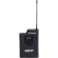
TM-1500 - Wireless Microphone Omnitronic - Free user manual and instructions
Find the device manual for free TM-1500 Omnitronic in PDF.


| Product Type | UHF wireless microphone set (receiver DR-1500, transmitter TM-1500, microphone HM-1500) |
| Brand | Omnitronic |
| Model | TM-1500 (set UHF-1500) |
| Frequency band | UHF 792.500 - 814.000 MHz (500 channels) |
| Modulation | FM (Frequency Modulation) |
| Frequency stability | ± 0.005 % |
| Audio bandwidth | 24 MHz |
| Signal-to-noise ratio | 105 dB |
| Range | Up to 200 m (with line of sight) |
| Receiver power supply | 230 V AC via external transformer 12-18 V DC, 600 mA |
| Transmitter power supply | 2 AA batteries (1.5 V) - 8 hours life |
| Microphone power supply | 2 AA batteries (1.5 V) - 8 hours life |
| Receiver dimensions | 210 x 175 x 45 mm |
| Receiver weight | 1 kg |
| Transmitter dimensions | 110 x 75 x 35 mm (antenna 105 mm) |
| Transmitter weight | 170 g |
| Microphone dimensions | 55 x 250 mm |
| Microphone weight | 400 g |
| Main functions | Diversity receiver, 500 channels, LCD display, volume control, 2 antennas, audio outputs XLR and 6.3 mm jack, colored caps included |
| Care and cleaning | Clean with a soft, damp cloth. Do not use alcohol or detergents. Disconnect before cleaning. |
| Safety | Protect from moisture. Disconnect before opening. Use only alkaline batteries. Observe polarity. Do not expose to temperatures >35°C or <5°C. |
| Spare parts and repairability | Use original parts. Repairs must be carried out by a qualified technician. |
| General information | EU approved (R&TTE directive). No declaration necessary in Germany. Warranty does not cover damage caused by failure to follow instructions. |
Frequently Asked Questions - TM-1500 Omnitronic
User questions about TM-1500 Omnitronic
0 question about this device. Answer the ones you know or ask your own.
Ask a new question about this device
Download the instructions for your Wireless Microphone in PDF format for free! Find your manual TM-1500 - Omnitronic and take your electronic device back in hand. On this page are published all the documents necessary for the use of your device. TM-1500 by Omnitronic.
USER MANUAL TM-1500 Omnitronic
BEDIENUNGSANLEITUNG
USER'S MANUAL
MODE D'EMPLOI
MANUAL DEL USUARIO
UHF-1500
Wireless Microphone Set
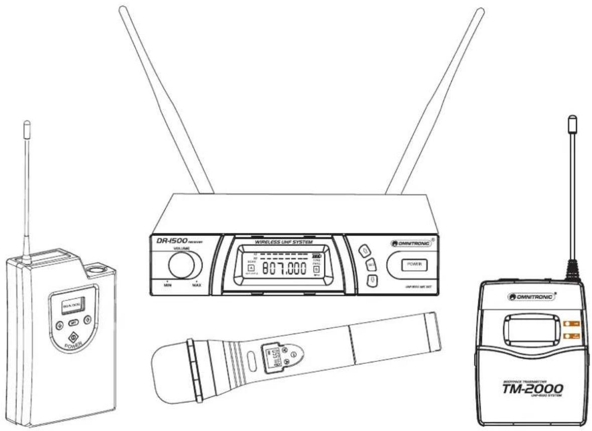
MULTI-LANGUAGE-INSTRUCTIONS
You can find the latest update of this user manual in the Internet under:
Zubehör
Handmikrofon HM-1500
natural_image
Two electronic components: a black cord with two U-shaped leads and a black rectangular charger connected to a power outlet (no text or symbols visible)Beschreibung
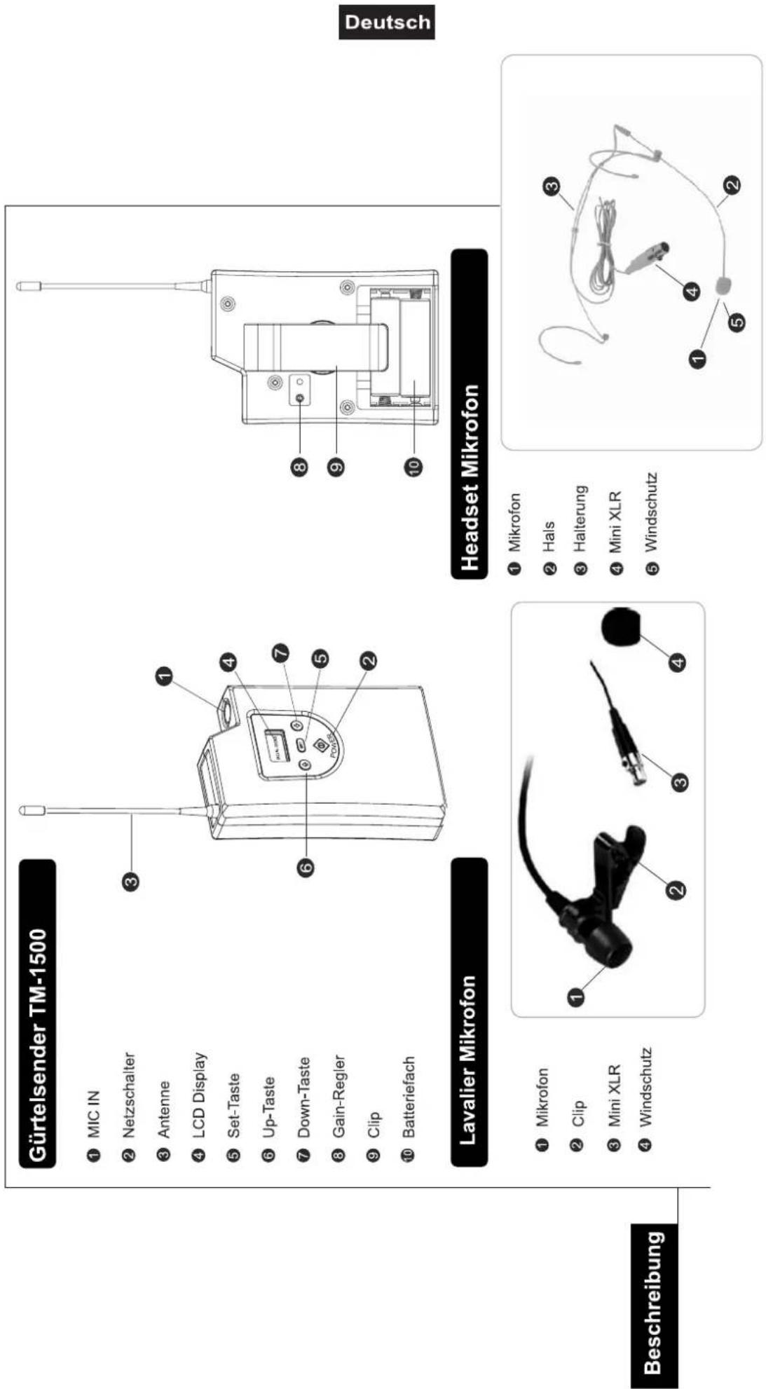
① Mikrofon
② Hals
③ Halterung
④ Mini XLR
⑤ Windschutz
① Mikrofon
② Clip
③ Mini XLR
④ Windschutz
Empfänger
(1.) Schritt 1
natural_image
Side profile illustration of a woman with hairpin and earband (no text or symbols)Operating Instructions
UHF-1500
Wireless Microhpone System

CAUTION!
Keep this device away from rain and moisture! Unplug mains lead before opening the housing!
For your own safety, please read this user manual carefully before you initial start-up.
Every person involved with the installation, operation and maintenance of this device has to
- be qualified
- follow the instructions of this manual
- consider this manual to be part of the total product
- keep this manual for the entire service life of the product
- pass this manual on to every further owner or user of the product
- download the latest version of the user manual from the Internet
Introduction
Thank you for having chosen an OMNITRONIC UHF-1500. If you follow the instructions given in this manual, we can assure you that you will enjoy this device for many years.
Unpack your OMNITRONIC UHF-1500.
Please make sure that there are no obvious transport damages. Should you notice any damage, do not take the device into operation and immediately consult your local dealer.
Wireless UHF microphone system
- Set includes stationary receiver and microphone in a practical suitcase
- The pocket transmitters TM-1500, TM-2000 or the lavalier microphone HS-500 have to be ordered separately
- 500 channels
- Up to 8 sets can be used simultaneously
- With two rubber antennas
• Operation in the low-interference UHF-band (792,500-814,000 MHz) - Display for power supply, signal input, frequency and battery power
- With output level control
- With external transformer
- Latest transmission technology in a rugged metal housing
- 2 x 1.5 V Mignon batteries (type AA) for Mic
• Operation range 200 meters - Delivery includes 6 colour caps and 1 meter jack-jack cable
• License-free and approved in Germany
Features
Safety Instructions
This device has left our premises in absolutely perfect condition. In order to maintain this condition and to ensure a safe operation, it is absolutely necessary for the user to follow the safety instructions and warning notes written in this user manual.

Important:
Damages caused by the disregard of this user manual are not subject to warranty. The dealer will not accept liability for any resulting defects or problems.
Always plug in the power unit last. Make sure that the power-switch is set to OFF position before you connect the device to the mains.
Keep away from heaters and other heating sources!
If the device has been exposed to drastic temperature fluctuation (e.g. after transportation), do not switch it on immediately. The arising condensation water might damage your device. Leave the device switched off until it has reached room temperature.
Never put any liquids on the device or close to it. Should any liquid enter the device nevertheless, disconnect from mains immediately. Please let the device be checked by a qualified service technician before you operate it again. Any damages caused by liquids having entered the device are not subject to warranty!
Always disconnect from the mains, when the device is not in use or before cleaning it.
CAUTION: Turn the amplifier on last and off first!
Please note that damages caused by manual modifications on the device or unauthorized operation by unqualified persons are not subject to warranty.
Keep away children and amateurs from the device and the batteries!
CAUTION: High volumes can cause hearing damage!
There are no serviceable parts inside the device. Maintenance and service operations are only to be carried out by authorized dealers.
Operating Determinations
This set consists of a wireless single antenna receiver and a wireless microphone. The receiver is allowed to be operated with a direct current of 12-18 V and was designed for indoor use only. Microphone and the optional pocket transmitter are only allowed to be operated with 2 x 1.5 V Mignon, AA batteries and were designed for indoor use only.
Batteries are hazardous waste which need to be disposed of appropriately. If the device is to be disposed, the batteries have to be removed first.
Make sure that the poles are correct when inserting the battery.
Never let batteries lying around openly as there is the danger that these can be swallowed by children or domestic animals. Immediately consult a doctor when batteries are swallowed!
Leaking or damaged batteries can cause irritations when getting into contact with the skin. In this case use appropriate protective gloves.
Make sure that the batteries cannot be short-circuited, thrown into the fire and be charged. There is a danger of explosion.
English
Never spill any liquids on the device. Should any liquid enter the device nevertheless, remove the batteries immediately. Please let the device be checked by a qualified service technician before you operate it again.
When choosing the installation-spot, please make sure that the device is not exposed to extreme heat, moisture or dust. There should not be any cables lying around. You endanger your own and the safety of others!
Do not operate the device in extremely hot (more than 30^ C) or extremely cold (less than 5^ C) surroundings. Keep away from direct insulation (particularly in cars) and heaters.
Operate the device only after having familiarized with its functions. Do not permit operation by persons not qualified for operating the device. Most damages are the result of unprofessional operation!
Never use solvents or aggressive detergents in order to clean the device! Rather use a soft and damp cloth.
Please use the original packaging if the device is to be transported.
Please consider that unauthorized modifications on the device are forbidden due to safety reasons!
If this device will be operated in any way different to the one described in this manual, the product may suffer damages and the guarantee becomes void. Furthermore, any other operation may lead to dangers like short-circuit, burns, electric shock, etc.
Approval
This wireless system was tested in accordance with the European standards EN 300422-2, EN 301489-09 and EN 60065. Consequently, this product adheres to the R&TTE directive of the European Union and does not need an individual EC type examination of every member state. The approval number is 1688.
In some countries, the operation of this wireless system needs to be approved by the national telecoms regulatory authority. Please refer to your authority via links from the following Internet address: http://ec.europa.eu/enterprise/rtte/weblinks.htm.
In Germany, this wireless system is generally approved and license-free.
Receiver
True-Diversity Receiver
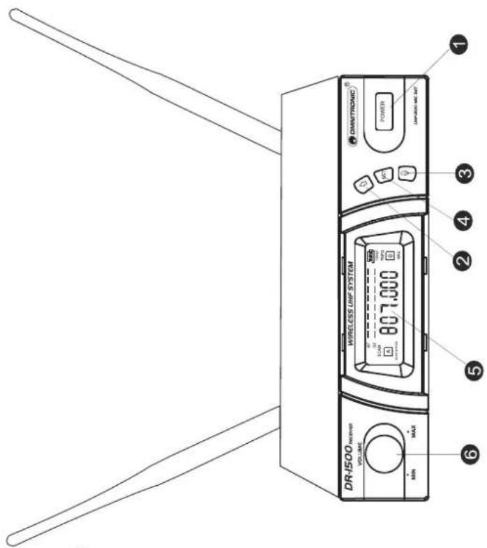
⑦ Dc socket for connection of main unit
⑧ AF output, jack socket (AF UNBAL)
⑨ AF output,jack socket (AF BAL)
⑩ Antenna II input socket
⑰ Antenna | input socket
⑫ Antenna
② Up button
③ Down button
④ Set button
⑤ LCD display
⑥ Volume control

English
Description
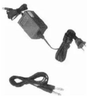
Standard Accessories
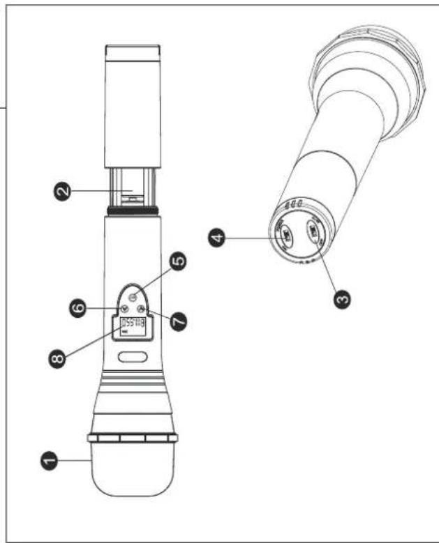
Handheld Transmitter
Handheld Transmitter
① Interchangeable Condenser capsule
② Battery tray
③ Battery tray button
④ Power On/Off switch
⑤ Set button
⑥ Down button
⑦ Up button
⑧ LCD display
natural_image
Two electronic components: a cord with two U-shaped leads and a charging plug (no text or symbols visible)Description
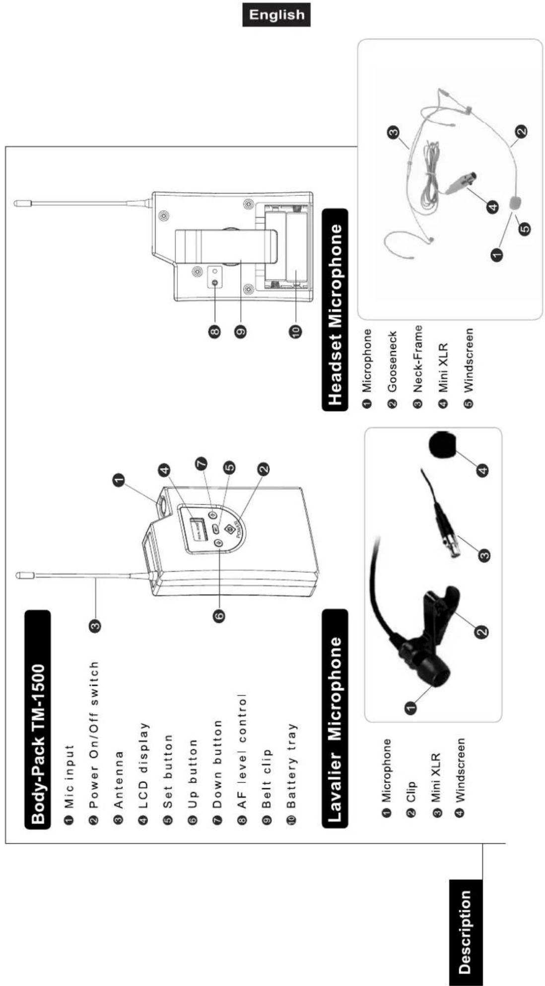
① Microphone
② Gooseneck
③ Neck-Frame
④ Mini XLR
⑤ Windscreen
Body-Pack TM-1500
① Mic input
② Power On/Off switch
③ Antenna
④ LCD display
⑤ Set button
⑥ Up button
⑦ Down button
⑧ AF level control
⑨ Belt clip
⑩ Battery tray
① Microphone
② Clip
③ Mini XLR
④ Windscreen
Description
Receiver
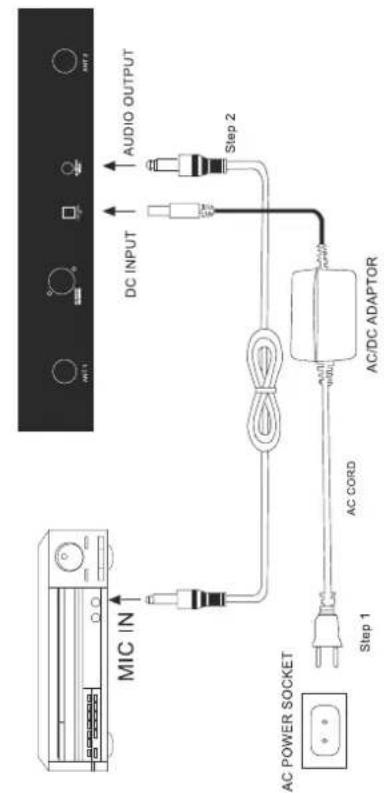
(1.) Power output connector
Plug in one end of AC/DC adaptor cable to DC input socket in the rear panel of receiver, and plug another end into an AC outlet (Step 1 of Figure 1)
(2.) Audio Output Connector
Connect one end of the AF output cable to the AF output socket in the rear panel, then plug another end to the "MIC IN" input socket of a mixer or amplifier.(Step 2 of Figure 1).equipped with balanced XLR output and unbalanced 6.3mm output, choose the proper way for use.
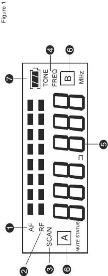
(3.) LCD panel
-
AF signal
-
RF signal
-
Display for SCAN mode
-
Display for set FREQ. mode
-
Main display
-
Diversity display (A or B antenna)
- Battery display for the transmitter
Operation
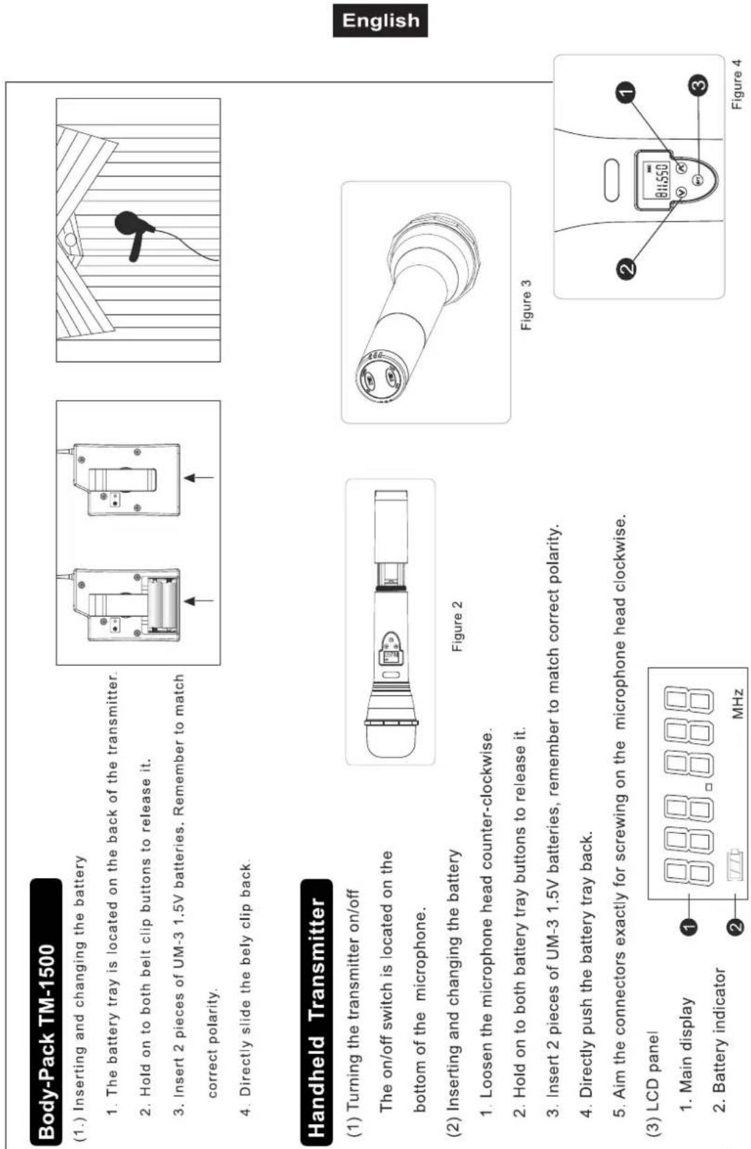
- The battery tray is located on the back of the transmitter.
- Hold on to both belt clip buttons to release it.
- Insert 2 pieces of UM-3 1.5V batteries. Remember to match
correct polarity. - Directly slide the bely clip back
- The battery tray is located on the back of the transmitter.
- Hold on to both belt clip buttons to release it.
- Insert 2 pieces of UM-3 1.5V batteries. Remember to match
correct polarity.
Body-Pack TM-1500
(1.) Inserting and changing the battery
Handheld Transmitter
(1) Turning the transmitter on/off
The on/off switch is located on the
bottom of the microphone.
(2) Inserting and changing the battery
-
Loosen the microphone head counter-clockwise.
-
Hold on to both battery tray buttons to release it.
-
Insert 2 pieces of UM-3 1.5V batteries, remember to match correct polarity.
-
Directly push the battery tray back.
-
Aim the connectors exactly for screwing on the microphone head clockwise.
(3) LCD panel
-
Main display
-
Battery indicator
Operation
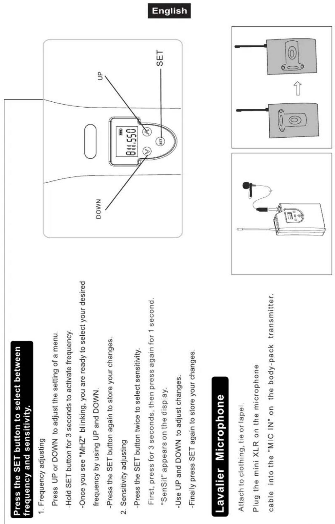
Press the SET button to select between frequency and sensitivity.
- Frequency adjusting
Press UP or DOWN to adjust the setting of a menu.
-Hold SET button for 3 seconds to activate frequency.
-Once you see "MHZ" blinking, you are ready to select your desired
frequency by using UP and DOWN.
-Press the SET button again to store your changes.
- Sensitivity adjusting
-Press the SET button twice to select sensitivity.
First, press for 3 seconds, then press again for 1 second.
"SenSit" appears on the display.
-Use UP and DOWN to adjust changes.
-Finally press SET again to store your changes.
Lavalier Microphone
Attach to clothing, tie or lapel.
Plug the mini XLR on the microphone
cable into the "MIC IN" on the body-pack transmitter.
Headset Microphone
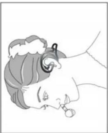
(2) With headset microphone
Put the neck-frame behind your neck meanwhile fix the temples on your ears.
natural_image
Line drawing of a woman wearing an earpiece, holding a small object near her mouth (no text or symbols)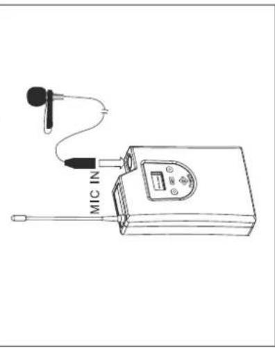
Basic operation TM-1500
- Frequency adjusting
-Hold SET button for 3 seconds to activate frequency.
-Once you see "MHz" blinking, you are ready to select your desired
frequency by using UP and DOWN buttons.
-Press the SET button again to store your changes.
- Sensitivity adjusting
-The sensitivity control (AF level control) is in the up-left of the
transmitter's back. Please use the adjusting sticker to adjust the
proper level.
- To activate "Lock mode"
-Hold on to UP button for 3 seconds to activate "Lock mode", press
again to unlock.
(Prevent accidental programming or switching off)
Operation
- In order to achieve the optimum reception condition and to extend the
operating distance, please leave an "open space" between receiver and
transmitter.
-
To avoid a feedback effect, do not aim the mic at speakers.
-
Avoid placing the receiver near computers or other RF generating equipment.
-
For best pick-up pattern, hold the mic at center position.
-
Adjust the signal level via the Volume-control. If the receiver is not in use,
please turn the Volume-control to 0 and switch the device off.
- IMPORTANT: Every wireless microphone installation is a unique situation,
and can present a variety of problems. Never attempt a live performance
without first conducting a test of the system in the performing area.
If major changes (additional wireless systems or intercoms, relocation
of scenery, etc.) have been made since the last test, check the wireless
system again - as close to performance time as possible.
Recommendation
Inserting/Replacing the batteries
Please refer to the explanations under Operating Determinations.
Caution!
Danger of explosion when battery is replaced improperly.
Only replace by the same type or similar types recommended by the manufacturer.
Remove empty batteries in accordance with the instructions of the manufacturer.
If the microphone is not used, switch it off via the slide switch. If the device will not be used for a longer period of time, remove the batteries in order to avoid battery leakage.
In order to have a long battery life, you should only use alcaline batteries.
BATTERY DISPOSAL NOTICE
Please dispose of old and used batteries properly.
Batteries are hazardous waste and should not be disposed of with regular domestic waste!
Please take old and used batteries to a collection center near you.
Batteries
PROBLEM: REMEDY:
| No power. ▪Check the connection cable of the power unit and any extension-cables. | |
| No sound; receiver RF-indicator does not flash. | □Make sure POWER switches on transmitter and receiver are on. ▪Check transmitter Power-LED to ensure that Battery is providing power. Replace battery if necessary. ▪Make sure that the receiver is in the line of sight of the transmitter. If necessary, reduce the distance between transmitter and receiver. |
| No receiver sound; receiver RF-indicator flashes. | □Turn up the receiver audio output LEVEL control. ▪Check for proper connection between receiver and microphone mixer. ▪Talk into the microphone and observe the receiver RF-indicator. If it flashes, the problem is elsewhere in the sound system. |
| Received signal is noisy or contains extraneous sounds with transmitter on. | □Check transmitter Power-LED to ensure that battery is providing power. ▪Remove local sources of RF interference, such as lighting equipment. ▪Two transmitters may be operating on the same frequency. Locate and turn one off. ▪Signal may be too weak. If possible, move receiver closer to the transmitter. |
| Noise from receiver with transmitter off. | □Remove local sources of RF interference, such as lighting equipment. ▪Reposition the receiver. |
| Momentary loss of sound as transmitter is moved around performing area. | □Reposition receiver and perform another test and observe the RF-indicator. If audio drop-outs persist, mark these dead spots in the performing area and avoid them during the performance. |

DANGER TO LIFE!
Disconnect from mains before starting maintenance operation!
We recommend a frequent cleaning of the device. Please use a soft lint-free and moistened cloth. Never use alcohol or solvents!
There are no servicable parts inside the device except for the batteries. Maintenance and service operations are only to be carried out by authorized dealers.
In order to replace the battery please refer to "Inserting/exchanging the batteries".
Should you need any spare parts, please use genuine parts.
Should you have further questions, please contact your dealer.
Cleaning and Maintenance
Technical Specifications
| UHF-1500 Set | |
| Carrier frequency: UHF 792.500-814.000 MHz | |
| Channel 61: 792.500-797.900 MHz | |
| Channel 62: 798.100-805.900 MHz | |
| Channel 63: 806.100-813.900 MHz | |
| Modulation: FM | |
| Switchable frequencies 500 | |
| Frequency stability: ± 0,005 % | |
| Band width 24 MHz | |
| T.H.D.: < 0.5% at 1 KHz | |
| S/N-ratio: 105 dB | |
| Input sensitivity: -105 dBm (12 dB S/N AD) | |
| Coverage: 200 m (with line-of-sight) | |
| Maximum deviation: ± 48.000 Hz | |
| RF power output: 10 mW | |
| E0055501 DR-1500 Receiver | |
| System: Switching Diversity, one channel | |
| AF output impendance: 2.2 kOhms | |
| Audio output level: -12 dB | |
| Audio output: | Mono 1/4" jack-socket or balanced XLR |
| Power supply: | 230 V AC, 50 Hz ~ via supplied 12-18 V DC, 600 mA adaptor |
| Power consumption: | 6 W |
| Dimensions: | 210 x 175 x 45 mm |
| Weight: | 1 kg |
| 13055512 TM-1500 Transmitter | |
| Power supply: | 2 x 1.5 V Mignon batteries (type AA) |
| Current consumption: | <100 mA @ 3V |
| Battery life: | approx. 8 hours |
| Audio input: | Mini-XLR |
| Dimensions (LxWxH): | 110 x 75 x 35 mm |
| Antenna (L): | 105 mm |
| Weight: | 170 g |
| E0055502 HM-1500 Microphone | |
| Type: | Hand-held condenser microphone |
| Directivity pattern: Cardioid (uni-directional) | |
| S/N-ratio: 60 dB | |
| Power supply: | 2 x 1.5 V Mignon batteries (type AA) |
| Current consumption: | <100 mA @ 3 V |
| Battery life: | approx. 8 hours |
| Dimensions: | 55 x 250 mm |
| Weight: | 400 g |
Please note: Every information is subject to change without prior notice. 19.02.2009 ©
MODE D'EMPLOI

OMNITRONIC

UHF-1500
Mode d'emploi
natural_image
Diagram showing a mechanical component being lifted, with no text or symbols present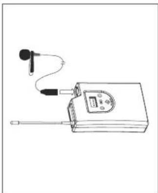
natural_image
Line drawing of a portable electronic device with antenna, ear, and control panel (no text or symbols)natural_image
Side profile illustration of a woman wearing an earpiece (no text or symbols)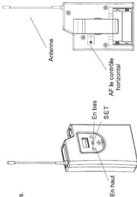
natural_image
Two electronic components: a cord with two U.S. connectors and a charging plug connected to a power outlet (no text or symbols visible)natural_image
Diagram showing a mechanical component being lifted from a left angle to a right angle, with no text or symbols present.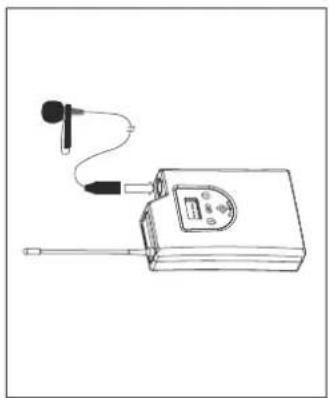
natural_image
Line drawing of a portable electronic device with antenna and earplifier (no text or symbols)natural_image
Line drawing of a woman wearing an earpiece with a pacifier (no text or symbols)- BEDIENUNGSANLEITUNG
- USER'S MANUAL
- MODE D'EMPLOI
- MANUAL DEL USUARIO
- UHF-1500
- Wireless Microphone Set
- MULTI-LANGUAGE-INSTRUCTIONS
- Handmikrofon HM-1500
- Empfänger
- Operating Instructions
- Wireless Microhpone System
- CAUTION!
- For your own safety, please read this user manual carefully before you initial start-up.
- Introduction
- Wireless UHF microphone system
- Features
- Safety Instructions
- Important:
- Operating Determinations
- English
- Approval
- Receiver
- Handheld Transmitter
- Body-Pack TM-1500
- Description
- Operation
- Press the SET button to select between frequency and sensitivity.
- Lavalier Microphone
- Headset Microphone
- Inserting/Replacing the batteries
- BATTERY DISPOSAL NOTICE
- DANGER TO LIFE!
- Technical Specifications
- OMNITRONIC
Brand : Omnitronic
Model : TM-1500
Category : Wireless Microphone