FWE04DAFN5V3-R - Air Conditioning DAIKIN - Free user manual and instructions
Find the device manual for free FWE04DAFN5V3-R DAIKIN in PDF.


| Brand | Daikin |
| Model | FWE04DAFN5V3-R |
| Product type | Fan coil unit without casing |
| Capacity category | 1.5 kW (03) |
| Number of pipes | 4 (heating and cooling) |
| Power supply | 220-240 V ~ 50 Hz, single-phase |
| Max. operating current | 0.46 A |
| Protection fuse | 16 A |
| Max. water pressure | 1 MPa |
| Water temperature min./max. | 5 °C / 90 °C |
| Motor type | V3 fan motor, single-phase |
| Installation | Horizontal (suspended) or vertical on floor (optional kit) |
| Required suction space | ≥ 150 mm |
| Space between ceiling and unit | ≥ 10 mm |
| Drainage piping slope | ≥ 1/100 |
| Air filter cleaning | Every 6 months (water or vacuum cleaner) |
| Electrical protection | Residual current device (RCD) compatible with inverter |
| Grounding | Mandatory, copper cable |
| Included documentation | Installation manual (paper), CE declaration |
| Country of manufacture | Hendek (factory code 5) |
Frequently Asked Questions - FWE04DAFN5V3-R DAIKIN
User questions about FWE04DAFN5V3-R DAIKIN
0 question about this device. Answer the ones you know or ask your own.
Ask a new question about this device
Download the instructions for your Air Conditioning in PDF format for free! Find your manual FWE04DAFN5V3-R - DAIKIN and take your electronic device back in hand. On this page are published all the documents necessary for the use of your device. FWE04DAFN5V3-R by DAIKIN.
USER MANUAL FWE04DAFN5V3-R DAIKIN
Installation manual Fan coil units
English
text_image
DAIKIN Hiromitsu Iwasaki Director Ostend, 3rd of September 2019 DAIKIN EUROPE N.V. Zandvoordestraat 300, B-8400 Oostende, Belgium2P491002-4E
Table of contents
1 About the documentation 3
1.1 About this document.... 3
1.2 Meaning of warnings and symbols 3
1.3 General....4
2 About the box 4
2.1 Overview: About the box 4
2.2 To unpack and handle the fan coil unit.... 4
2.3 To remove the accessories from the fan coil unit.... 4
3 About the unit 4
3.1 Overview: About the units and options.... 4
3.2 Identification 5
3.2.1 Identification label: Fan coil unit.... 5
4 Preparation 5
4.1 Overview: Preparation....5
4.2 Preparing the installation site 5
4.3 Preparing water piping 6
4.4 Preparing electrical wiring 6
4.4.1 About preparing the electrical wiring....6
5 Installation 7
5.1 Mounting the fan coil unit 7
5.1.1 Horizontal installation....7
5.1.2 Vertical installation....8
5.2 Changing from horizontal to vertical installation....8
5.3 Connecting the water piping....9
5.3.1 To connect the water piping....9
5.3.2 To fill the water circuit 10
5.4 Connecting the electrical wiring.... 10
5.4.1 About connecting the electrical wiring.... 10
5.4.2 Guidelines when connecting the electrical wiring ..... 10
5.4.3 To connect the electrical wiring on the fan coil unit ... 10
5.4.4 To change the electrical wiring direction.... 10
5.5 Connecting the drain piping 12
5.5.1 To install the drain piping to the unit 12
5.5.2 To check the drain piping.... 13
6 Commissioning 13
6.1 To perform a test run.... 13
6.2 Checklist before commissioning.... 14
7 Maintenance and service 14
7.1 To clean the air filter.... 14
8 Technical data
8.1 Dimensions.... 16
8.2 Wiring diagram 18
8.3 Information requirements for Eco Design.... 19
8 Technical data
[Non-Text]
8 Technical data
[Non-Text]
[Non-Text]
8 Technical data
[Non-Text]
8 Technical data
[Non-Text]
[Non-Text]
[Non-Text]
8 Technical data
[Non-Text]
[Non-Text]
[Non-Text]
[Non-Text]
[Non-Text]
[Non-Text]
[Non-Text]
[Non-Text]
[Non-Text]
[Non-Text]
[Non-Text]
FWE03\~11D
Fan coil units
3P443944-5E - 2019.09
DAIKIN
Installation manual
1 About the documentation
1.1 About this document
Target audience
Authorised installers

INFORMATION
This appliance is intended to be used by expert or trained users in shops, in light industry, and on farms, or for commercial and household use by lay persons.
Documentation set
This document is part of a documentation set. The complete set consists of:
Latest revisions of the supplied documentation may be available on the regional Daikin website or via your dealer.
The original documentation is written in English. All other languages are translations.
- Fan coil unit installation manual:
- Installation instructions
- Format: Paper (in the box of the fan coil unit)
1.2 Meaning of warnings and symbols

DANGER
Indicates a situation that results in death or serious injury.

DANGER: RISK OF ELECTROCUTION
Indicates a situation that could result in electrocution.

DANGER: RISK OF BURNING
Indicates a situation that could result in burning because of extreme hot or cold temperatures.

DANGER: RISK OF EXPLOSION
Indicates a situation that could result in explosion.

WARNING
Indicates a situation that could result in death or serious injury.

WARNING: FLAMMABLE MATERIAL

CAUTION
Indicates a situation that could result in minor or moderate injury.

NOTICE
Indicates a situation that could result in equipment or property damage.

INFORMATION
Indicates useful tips or additional information.
| Symbol | Explanation |
| Before installation, read the installation and operation manual, and the wiring instruction sheet. | |
| Before performing maintenance and service tasks, read the service manual. | |
| For more information, see the installer and user reference guide. |
3P443944-5E - 2019.09
2 About the box
1.3 General
If you are NOT sure how to install or operate the unit, contact your dealer.

NOTICE
Improper installation or attachment of equipment or accessories could result in electric shock, short-circuit, leaks, fire or other damage to the equipment. Only use accessories, optional equipment and spare parts made or approved by Daikin.

WARNING
Make sure installation, testing and applied materials comply with applicable legislation (on top of the instructions described in the Daikin documentation).

CAUTION
Wear adequate personal protective equipment (protective gloves, safety glasses,...) when installing, maintaining or servicing the system.

WARNING
Tear apart and throw away plastic packaging bags so that nobody, especially children, can play with them. Possible risk: suffocation.

WARNING
Provide adequate measures to prevent that the unit can be used as a shelter by small animals. Small animals that make contact with electrical parts can cause malfunctions, smoke or fire.

CAUTION
Do NOT touch the air inlet or aluminium fins of the unit.

NOTICE
- Do NOT place any objects or equipment on top of the unit.
- Do NOT sit, climb or stand on the unit.

DANGER: RISK OF ELECTROCUTION
- Make sure that the system is earthed properly.
- Turn off the power supply before servicing.
- Install the switch box cover before turning on the power supply.

CAUTION
- Check if the installation location can support the unit's weight. Poor installation is hazardous. It can also cause vibrations or unusual operating noise.
- Provide sufficient service space.
- Do NOT install the unit so that it is in contact with a ceiling or a wall, as this may cause vibrations.

DANGER: RISK OF ELECTROCUTION
Do not operate the fan coil units with wet hands. An electric shock may result.
2 About the box
2.1 Overview: About the box
Keep the following in mind:
- At delivery, the unit MUST be checked for damage. Any damage MUST be reported immediately to the claims agent of the carrier.
- Bring the packed unit as close as possible to its final installation position to prevent damage during transport.
• Prepare the path along which you want to bring the unit inside in advance.
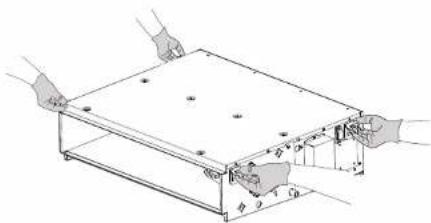
2.2 To unpack and handle the fan coil unit
Use a sling of soft material or protective plates together with a rope when lifting the unit. This to avoid damage or scratches to the unit.
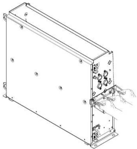
1 Lift the unit by holding onto the hanger brackets without exerting any pressure on other parts, especially on drain piping and thermal insulation.
text_image
Technical diagram showing hands operating a rectangular frame with labeled dimensions and components2.3 To remove the accessories from the fan coil unit
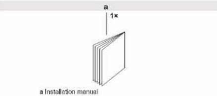
text_image
a 1x a Installation manual3 About the unit
3.1 Overview: About the units and options
This chapter contains information about:
• Identifying the fan coil unit.
3.2 Identification
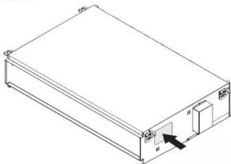
3.2.1 Identification label: Fan coil unit
Location
natural_image
Isometric line drawing of a rectangular electronic device with a small internal component and labeled terminals (no text or symbols present)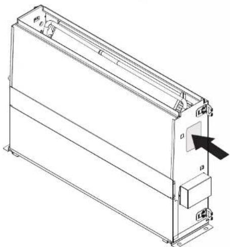
natural_image
Technical line drawing of a rectangular electronic device with mounting brackets and a control panel (no text or symbols)Model identification
Example: FW E 03 D A F N 5 V3 — L
| Code Description | |
| FW Water fan coil unit | |
| E Flex Low Static Pressure (LSP) without casing | |
| 03 Capacity class: 03=1.5 kW | |
| D Major model change (A to Z) | |
| A Minor change | |
| F 4 pipe | |
| N Without valve | |
| 5 Hendek factory | |
| V3 Fan motor / single phase / 50 Hz / 220~240 V | |
| — No option | |
Code Description
| L: Left side water – Left side electric connection |
| L: Left side water – Right side electric connection |
| T: Right side water – Right side electric connection |
| R: Right side water – Left side electric connection |
4 Preparation
4.1 Overview: Preparation
This chapter describes what you have to do and know before going on-site.
It contains information about:
• Preparing the installation site
- Preparing the water piping
• Preparing the electrical wiring
4.2 Preparing the installation site

WARNING
Do NOT place objects below the fan unit that may get wet. Otherwise condensation on the main unit or water pipes, air filter dirt or drain blockage may cause dripping, resulting in fouling or failure of the object concerned.

NOTICE
Please consult with your dealer to ensure that the external static pressure of the unit is not exceeded.
Do not install or operate the unit in rooms mentioned below.
- Places with mineral oil, or filled with oil vapour or spray like in kitchens (plastic parts may deteriorate).
- Where corrosive gas like sulphurous gas exists. Copper tubing and brazed spots may corrode.
- Where the air contains high levels of salt such as that near the ocean and where voltage fluctuates a lot, (e.g. in factories). Also in vehicles or vessels.
- In places where there is machinery that emits electromagnetic waves. Electromagnetic waves may disturb the control system, and cause malfunction of the equipment.
- In places where there is a risk of fire due to the leakage of flammable gases (example: thinner or gasoline), carbon fibre, ignitable dust.
Select an installation site where the following conditions are fulfilled and that meets your customer approval.
The space around the unit is adequate for maintenance and servicing. The space around the unit allows sufficient air circulation and air distribution see space required for installation.
Horizontal installation
The unit must be installed ≥2.5 m from the floor where the unit is hanging in the ceiling.
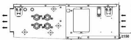
text_image
≥1504 Preparation
Vertical installation
Vertical filter maintenance space should be considered as indicated.
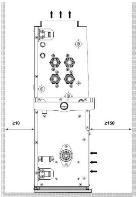
text_image
≥10 ≥150
CAUTION
Do not use suspension bolts in case of vertical installation. Vertical installation must be performed with the vertical installation kit (ESFH01DS).
4.3 Preparing water piping
The unit is equipped with a water inlet and water outlet for connection to the water circuit. The water circuit must be provided by an installer and must comply with the applicable legislation.

NOTICE
The unit is only to be used in a closed water system. Application in an open water circuit can lead to excessive corrosion of the water piping.
Before performing the water piping work, check the following points:
- The maximum water pressure is 1 MPa.
- The minimum water temperature is 5^ .
- The maximum water temperature is 90°C.
- Be sure to install components in the field piping that can withstand the water pressure and temperature.
- Provide adequate safeguards in the water circuit to ensure that the water pressure will never exceed the maximum allowable working pressure.
- Provide a proper drain for the pressure relief valve (if installed) to avoid any water from coming into contact with electrical parts.
-
Provide shut-off valves at the unit so that normal servicing can be accomplished without draining the system.
-
Provide drain taps at all low points of the system to permit complete draining of the circuit during maintenance or service to the unit.
- Provide air purge valves at all high points of the system. The valves shall be located at points which are easily accessible for servicing.
4.4 Preparing electrical wiring
4.4.1 About preparing the electrical wiring

WARNING
• ONLY use copper wires.
- Make sure the field wiring complies with the applicable legislation.
- All field wiring MUST be performed in accordance with the wiring diagram supplied with the product.
- NEVER squeeze bundled cables and make sure they do NOT come in contact with the piping and sharp edges. Make sure no external pressure is applied to the terminal connections.
- Make sure to install earth wiring. Do NOT earth the unit to a utility pipe, surge absorber, or telephone earth. Incomplete earth may cause electrical shock.
- Make sure to use a dedicated power circuit. NEVER use a power supply shared by another appliance.
- Make sure to install the required fuses or circuit breakers.
- Make sure to install an earth leakage protector. Failure to do so may cause electric shock or fire.
- When installing the earth leakage protector, make sure it is compatible with the inverter (resistant to high frequency electric noise) to avoid unnecessary opening of the earth leakage protector.

NOTICE
The equipment described in this manual may cause electronic noise generated from radio-frequency energy. The equipment complies to specifications that are designed to provide reasonable protection against such interference. However, there is no guarantee that interference will not occur in a particular installation.
It is therefore recommended to install the equipment and electric wires keeping proper distances away from stereo equipment, personal computers, etc.

WARNING
All field wiring and components MUST be installed by a licensed electrician and MUST comply with the applicable legislation.

DANGER: RISK OF ELECTROCUTION

WARNING
A main switch or other means for disconnection, having a contact separation in all poles, MUST be incorporated in the fixed wiring in accordance with the applicable legislation.
5 Installation
Electrical characteristics
| FWE-D | |
| Phase 1N~ | |
| Frequency 50 Hz | |
| Voltage range 220~240 V | |
| Voltage tolerance ±10% | |
| Maximum running current 0.46 A | |
| Overcurrent fuse 16 A |
Specifications for field wiring
| Wire Size (mm2) | Length | ||
| Power supply wiring | H05VV-U3G(1)(2) | According to the applicable legislation ≤ 4.0 | — |
| Remote controller and unit transmission wiring | Sheathed wire 2 conductors(3) | 0.75-1.25 ≤500 m | (4) |
^60 Only in case of protected pipes. Use H07RN-F in case of no protection.
^a Run electrical wiring through a conduit to protect against external forces.
Use double insulation wire for remote controller (sheath thickness ≥1 mm) or run wires through a wall or conduit so that the user cannot come in contact with them.
^14 The length shall be the total extended length in a system with group control.
5 Installation
5.1 Mounting the fan coil unit

INFORMATION
The spacing between ceiling and unit should be ≥ 10 mm and the suction space should be ≥ 150 mm.

INFORMATION
All the above parts are field supplied. For installation other than standard installation, contact your local dealer for advice.
5.1.1 Horizontal installation
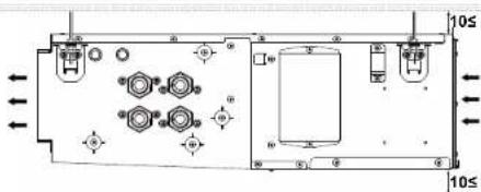
text_image
10S 10≤1 Make the required ceiling opening for installation in an applicable place.
It may be necessary to reinforce the suspended ceiling frame to keep the ceiling level and to prevent it from vibrating. Consult the builder for details.
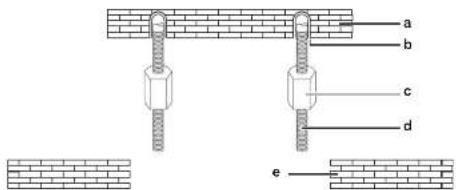
2 Install the suspension bolts. Use either W3/8 or M10 size bolts. Use anchors for existing ceilings, and a sunken insert, sunken anchors or other field supplied parts for new ceilings to reinforce the ceiling in order to bear the weight of the unit. Refer to it to check for points requiring reinforcing. Adjust the clearance from the ceiling before proceeding further.
text_image
a b c d ea Ceiling slab
b Anchor
c Long nut or turn-buckle
d Suspension bolt
e Suspended ceiling
3 Install the unit temporarily.
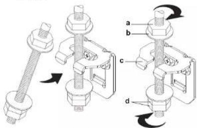
Attach the hanger bracket to the suspension bolt. Fix the unit securely.
text_image
Technical diagram showing mechanical assembly with labeled parts a, b, c, d and directional arrows indicating movement or transformation.a Nut (field supply)
b Washer (field supply)
c Hanger bracket
d Double nut (field supply)
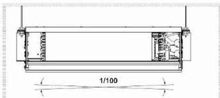
4 Adjust the unit to the correct position for installation.
text_image
1/1005 Check if the unit is horizontally levelled.
Do not install the unit tilted. If the unit is tilted against the direction of the condensate flow (drain piping side raised), it will cause water to drip.
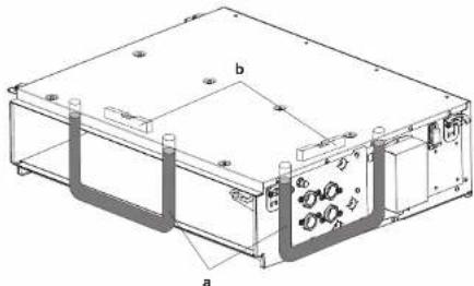
Check if the unit is levelled at all 4 comers with a water level or a water-filled plastic tube.
natural_image
Technical line drawing of a rectangular electronic device with labeled components (a, b), no readable text or symbols present.a Plastic tube
b Level
5 Installation
5.1.2 Vertical installation

NOTICE
Do NOT use excessive force when connecting the piping. Deformation of the piping can cause malfunctioning of the unit. Make sure that the tightening torque is 3 N·m for all screws.

NOTICE
The option kit (ESFH01DS) should be provided by a local dealer to install the unit vertically.
1 Install the unit temporarily.
Install the unit on the floor with installation legs. Be sure to place the unit on the floor securely. If there is a risk that the unit will topple, fix it to the floor using screws in the installation leg holes.
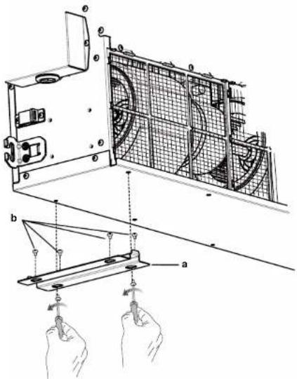
text_image
Technical diagram showing installation of a fan blade assembly with labeled components and hand positionsa Installation leg
b Fixing screw
2 Adjust the unit to the correct position for installing.
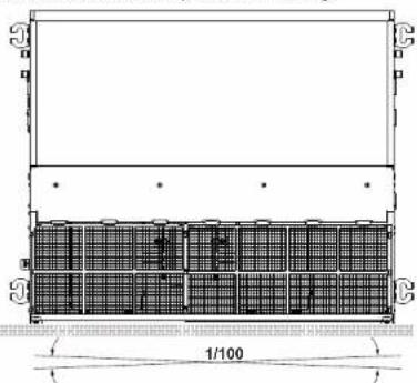
natural_image
Architectural cross-section diagram of a building facade with grid pattern and dimension label (no text or symbols beyond basic geometry)a Level
b Plastic tube
3 Check if the unit is horizontally levelled.
Do not install the unit tilted. If the unit is tilted against the direction of the condensate flow (drain piping side raised), it will cause water to drip.
Check if the unit is levelled at all four comers with a water level or a water-filled plastic tube.
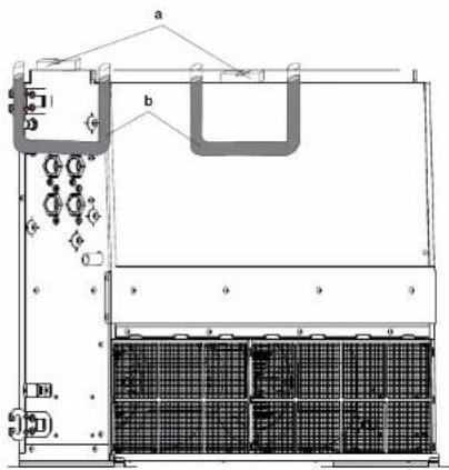
text_image
Technical diagram of a server rack with labeled components and internal grid structure5.2 Changing from horizontal to vertical installation

CAUTION
Make sure that the unit is levelled in all directions.
In case of changing from horizontal to vertical installation, please follow the intructions below.
1 Remove the air filter.
2 Remove the screws in the service cover and remove it from the unit.
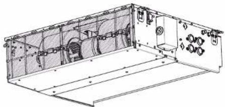
natural_image
Technical line drawing of an industrial enclosure or enclosure with internal components and mounting holes (no text or symbols)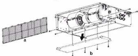
text_image
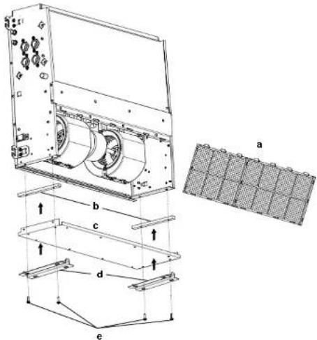
a b3 Insert the rubber support (included in the option kit) in the free area between the side plate and the bottom flanges.
4 Reattach the removed service cover to the bottom side.
5 Attach 2 installation legs from the vertical installation option kit to the service cover with the 4 screws from the option kit.
6 Reattach the air filter on the service cover filter guide.
7 The unit is ready for vertical installation.
text_image
Technical diagram of a mechanical assembly with labeled components and cross-sectional view
natural_image
Technical line drawing of a server rack unit with grid and control panel (no text or symbols)a Air filter
b Service power
B Service Cover
c Installation legs
d Screws
e Air filter
5.3 Connecting the water piping

NOTICE
Do not use excessive force when connecting the piping. This could deform the unit piping. Deformation of the piping can cause the unit to malfunction.

CAUTION
Valves should always be used to control the water circulation in the unit. The valve should be of the NC (normally closed) type so that the valves are closed when the unit is not operating. This will prevent condensate water from being produced.
5.3.1 To connect the water piping
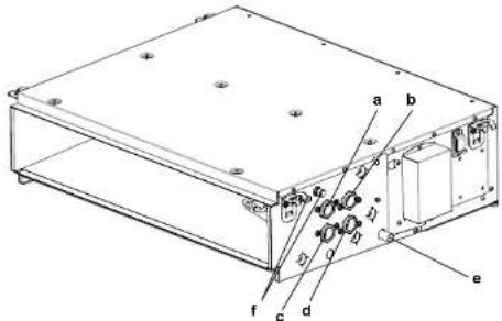
1 Connect the water inlet and outlet connections of the fan coil unit to the water piping.
text_image
Technical diagram of an electronic device with labeled components and internal wiring connectionsa Drain pipe connection (3/4"male)
b Chilled water inlet (3/4" female BSP)
c Chilled water outlet (3/4" female BSP
d Heating water inlet (3/4" female BSP)
a. Floating water outlet (2/4" female) RCF
e Heating water outlet (3/4 female BSP
g Air purge valve
Remark: Use a 3/4" male BSP pipe in case of direct connection to the unit.
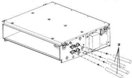
2 The complete water circuit, including all piping, must be insulated to prevent condensation and reduced capacity.
text_image
Technical diagram of an electronic device with labeled components and directional arrows indicating motion or flow.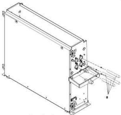
natural_image
Technical line drawing of an electronic device casing with internal components and mounting brackets (no text or symbols)a Connection pipe
5 Installation
5.3.2 To fill the water circuit

NOTICE
Make sure water quality complies with EU directive 98/83 EC.

NOTICE
- Air in the water circuit can cause malfunctioning. During filling, it may not be possible to remove all the air from the circuit. Remaining air will be removed through the automatic air purge valves during the initial operating hours of the system. Additional filling with water afterwards may be required. - To purge the system, use the special function as described in "6 Commissioning" on page 13.
1 Open the cap.
2 Push the pressure relief valve to purge air from the unit water circuit(s).
3 Close the cap.
4 Additional filling with water afterwards might be required (but never through the air purge valve).
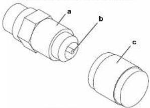
text_image
a b ca Air purge
b Pressure relief valve
c Cap
5.4 Connecting the electrical wiring
5.4.1 About connecting the electrical wiring
Typical workflow
Connecting the electrical wiring typically consists of the following stages:
1 Making sure the power supply system complies with the electrical specifications of the units.
2 Connecting the electrical wiring to the fan coil unit.
3 Changing the electrical wiring direction (if applicable).
5.4.2 Guidelines when connecting the electrical wiring
When connecting wires of the same gauge, connect them according to the figure below.
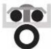
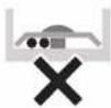

Observe the notes mentioned below when connecting the electrical wiring.
- Do not connect wires of different gauge to the same power supply terminal. Looseness in the connection may cause overheating.
- Do not connect wires of different gauge to the same grounding terminal. Looseness in the connection may deteriorate the protection.
Installation manual
DAIKIN
- Use the specified electric wire (refer to "Specifications for field wiring" on page 7). Connect the wire securely to the terminal. Use the appropriate tightening torque (N·m).
• Power supply terminal block tightening torque: 1.44–1.88 N·m. - Keep the wiring neat so that wires do not obstruct other equipment or force the terminal cover to pop open. Make sure the cover closes tight. Incomplete connections could result in overheating, and in the worst case, electric shock or fire.
5.4.3 To connect the electrical wiring on the fan coil unit
Refer to the wiring diagram sticker on the terminal cover.

NOTICE
- Follow the wiring diagram (delivered with the unit, located on the switch box cover).
- Make sure the electrical wiring does NOT obstruct proper reattachment of the service cover.
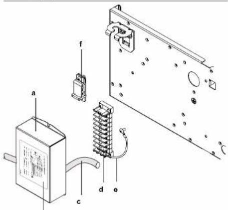
text_image
Technical diagram of an electrical component with labeled parts including a box, fuse, and coil connectionb
a Terminal cover
b Sticker
c Power supply cable
d Terminal strip
e Earth wire
f Cable holder
1 Remove the terminal cover and the cable holder from the unit.
2 Connect the power supply cable to the terminal strip.
3 Fix the power supply cable with the cable holder.
4 Reattach the terminal cover to the unit.
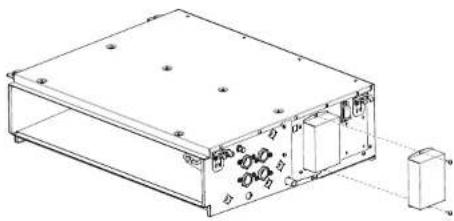
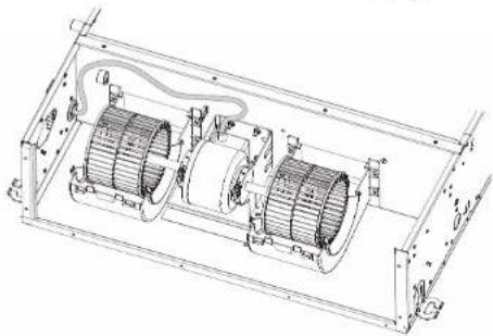
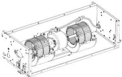
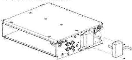
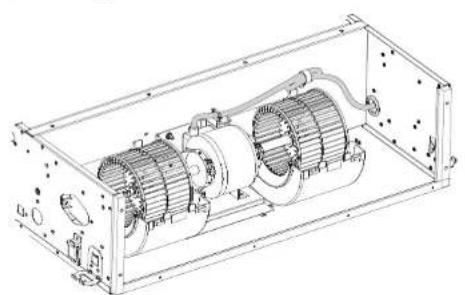
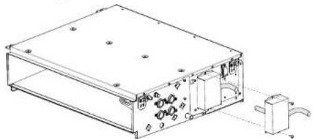
5.4.4 To change the electrical wiring direction

NOTICE
The electrical wiring direction can be changed to the opposite side in the field.

NOTICE
When attaching the terminal cover, make sure not to pinch any wires.
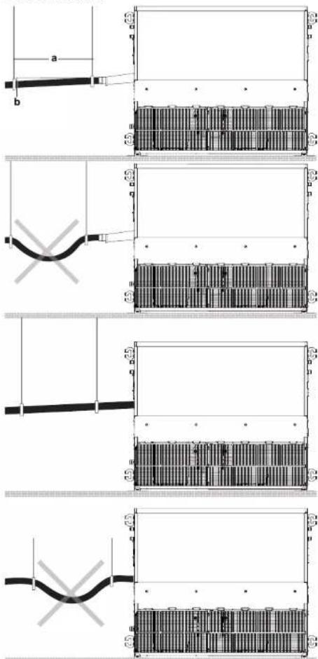
1 Remove the terminal cover, terminal, cable holder, earth wire and fan motor cables.
FWE03-11D
Fan coil units
3P443944-5E - 2019.09
5 Installation
natural_image
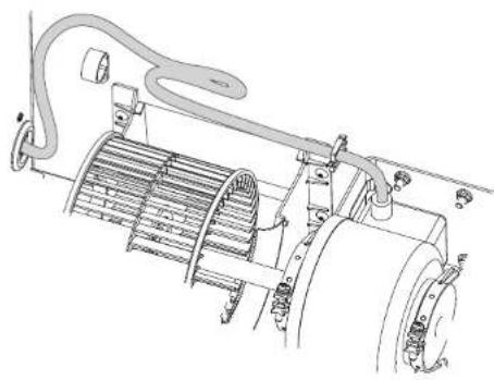
Technical line drawing of a rectangular electronic device with mounting holes and internal components (no text or symbols)2 Release the fan motor cables from the cable holders.
natural_image
Technical line drawing of a mechanical assembly with hoses and components (no text or symbols)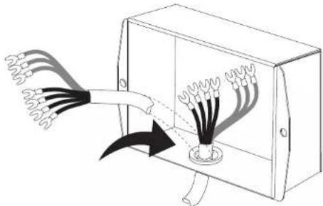
natural_image
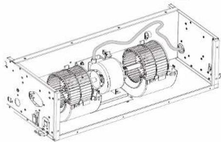
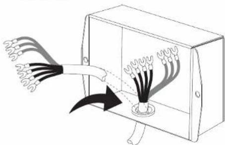
Diagram of a device emitting wires from a junction box, showing light rays and internal components (no text or symbols)3 Change the direction of the fan motor cables.
natural_image
Technical line drawing of a mechanical assembly with two cylindrical components and internal wiring (no text or symbols)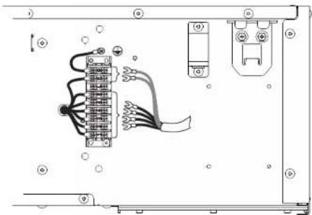
natural_image
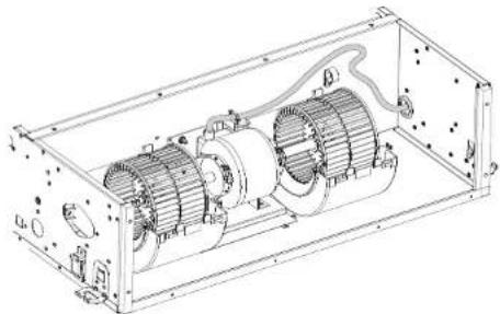
Pure electrical circuit lines without any symbols4 Fix the cables to the partition plate. Make sure that unused cables are fixed tightly with a cable clamp in the new position.
natural_image
Technical line drawing of an electric motor assembly inside a rectangular frame (no text or labels)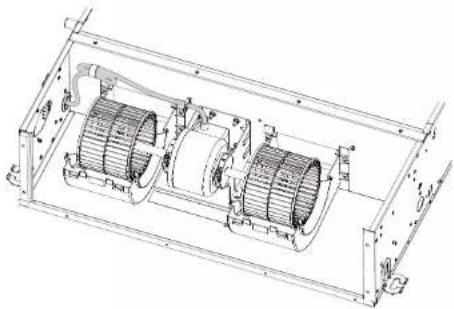
natural_image
Technical line drawing of an internal mechanical assembly with two main gears and housing (no text or labels)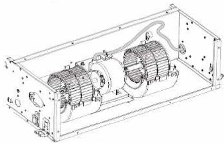
natural_image
Technical line drawing of an internal combustion engine assembly (no text or labels)5 Installation
natural_image
Technical line drawing of an electric motor enclosed in a transparent enclosure (no text or symbols)5 Fix the removed parts to the unit.
text_image
a b a bVertical installation
natural_image
Technical line drawing of a rectangular electronic device with mounting holes and internal components (no text or symbols)6 Install the removed cable holder to fix the cable.
text_image
a b a b c d e f g h i j k l m n o p q r s t u v w x y z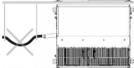
natural_image
Pure electrical circuit lines without any symbols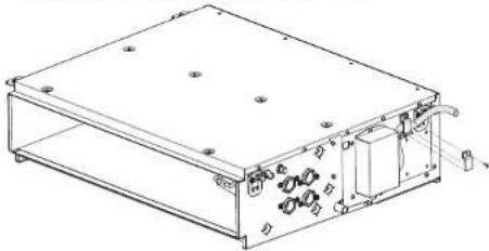
natural_image
Technical line drawing of a rectangular electronic device with internal components and mounting holes (no text or symbols)5.5 Connecting the drain piping
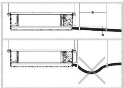
5.5.1 To install the drain piping to the unit
Horizontal installation
text_image
Technical diagram showing two mechanical components with labeled dimensions a and b, including internal structures and a wire connection.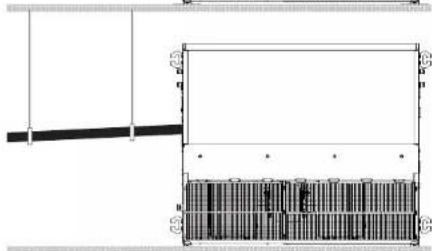
natural_image
Architectural floor plan showing room layout and structural elements (no text or labels)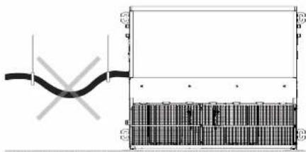
natural_image
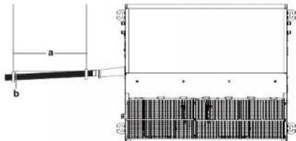
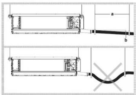
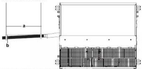
Pure electrical circuit lines without any symbolsa Hanging bar
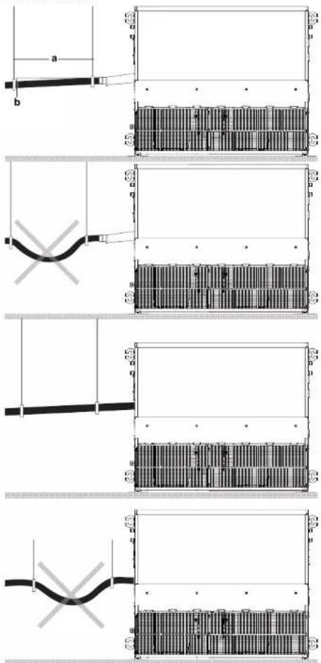
b ≥1/100 gradient
Keep piping as short as possible and slope it downwards at a gradient of at least 1/100 so that air does not remain trapped inside the pipe.
5.5.2 To check the drain piping
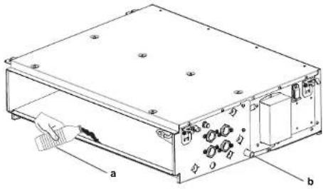
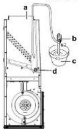
After the drain piping work is finished, check if drainage flows smoothly.
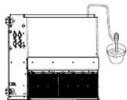
1 Add approximately 1 liter of water gradually through the air outlet.
natural_image
Technical line drawing of a rectangular electronic device with labeled components (a and b), no readable text or symbols present.a Plastic watering bottle
b Drain socket
text_image
a b c da Air outlet
b Portable pump
c Bucket
d Drain socket
natural_image
Simple line drawing of a laboratory apparatus with a beaker, tubing, and a beaker with liquid (no text or symbols)2 Check the drainage flow and confirm the drain operation looking at the drain socket.
6 Commissioning
Please provide the eco design data according to (EU)2016/2281 to the customer. This data can be found in the installer reference guide or via the Daikin website.

NOTICE
ALWAYS operate the unit with thermistors and/or pressure sensors/switches. If NOT, burning of the compressor might be the result.
6.1 To perform a test run
After installation, the installer is obliged to verify correct operation. In case something is wrong with the unit and it does not operate, contact your local dealer.

NOTICE
Do not interrupt the test run.

NOTICE
Do NOT try to dismantle the system yourself: dismantling of the system, treatment of the refrigerant, oil and other parts MUST comply with applicable legislation. Units MUST be treated at a specialised treatment facility for reuse, recycling and recovery.

WARNING
Provide adequate measures to prevent that the unit can be used as a shelter by small animals. Small animals that make contact with electrical parts can cause malfunctions, smoke or fire.
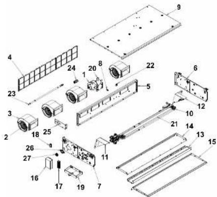
Use proper tool for removing the screws. The product can be disassembled as shown below.
text_image
Exploded view diagram of an electronic device with numbered components for identification| FWE-D Recycle instruction list | |
| Materials Item | |
| Electrical part (fan motor + capacitor) | 1 |
| Aluminium (fin) + copper (tube) + galvanized steel (plate) + brass | 10 |
| Plastic 2, 18, 8, 22, 27 | |
| Plastic + metal | 3, 17, 24 |
| Plastic (frame) + plastic (net) | 4 |
| Galvanized steel | 5, 9, 13, 14, 16, 20, 23, 25, 26 |
| Galvanized steel + plastic foam | 6, 7, 11, 12, 15, 19 |
| Plastic foam | 21 |
7 Maintenance and service
6.2 Checklist before commissioning
After the installation of the unit, first check the items listed below. Once all checks are fulfilled, the unit must be closed. Power-up the unit after it is closed.
| InstallationCheck that the unit is properly installed, to avoid abnormal noises and vibrations when starting up the unit. | |
| DrainageMake sure drainage flows smoothly.Possible consequence: Condensate water might drip. | |
| Power supply voltageCheck the power supply voltage on the local supply panel.The voltage MUST correspond to the voltage on the identification label of the unit. | |
| Earth wiringBe sure that the earth wires have been connected properly and that the earth terminals are tightened. | |
| Fuses, circuit breakers, or protection devicesCheck that the fuses, circuit breakers, or the locally installed protection devices are of the size and type specified in "4.4 Preparing electrical wiring" on page 6. Be sure that neither a fuse nor a protection device has been bypassed. | |
| Internal wiringVisually check the electrical component box and the inside of the unit for loose connections or damaged electrical components. | |
| Damaged equipmentCheck the inside of the unit on damaged components or squeezed pipes. | |
| Air inlet/outletCheck that the air inlet and outlet of the unit is NOT obstructed by paper sheets, cardboard, or any other material. |
7 Maintenance and service

NOTICE
Maintenance MUST be done by an authorized installer or service agent.
We recommend performing maintenance at least once a year. However, applicable legislation might require shorter maintenance intervals.
7.1 To clean the air filter
When
- Clean every 6 months. If the air in the room is extremely contaminated, increase the cleaning frequency.
- If the dirt becomes impossible to clean, change the air filter with original equipment.
How
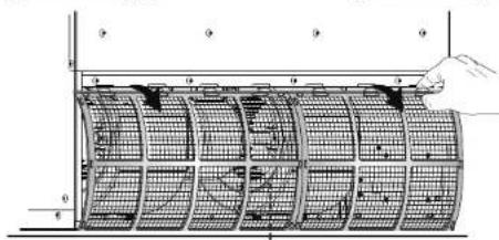
1 Switch off the power supply.
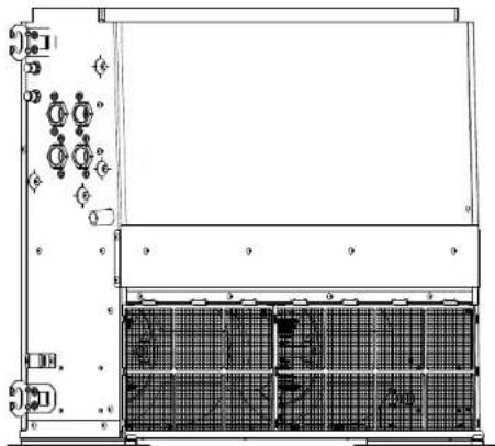
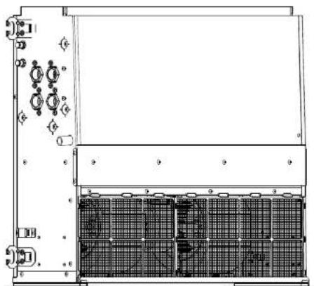
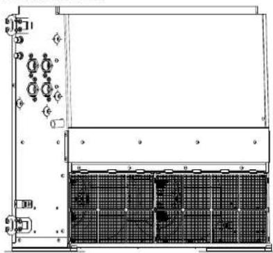
2 The air filter can be installed in 1 of 2 locations on this product (side and bottom). Remove the filter by sliding as shown below.
Installation manual
DAIKIN
Horizontal installation
Remove the filter by sliding.

natural_image
Technical line drawings of an electronic device chassis showing internal components and mounting points (no text or symbols)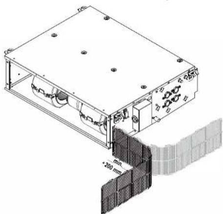
natural_image
Technical line drawing of a mechanical device with mounting holes and a 200 mm dimension label (no readable text or symbols beyond measurement annotations)FWE03\~11D
Fan coil units
3P443944-5E - 2019.09
7 Maintenance and service
Vertical installation
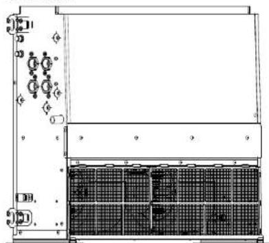
Push the tabs at the filter and pull it back.
natural_image
Technical line drawing of a mechanical or electrical enclosure with internal grid structure (no text or symbols)3 Use a vacuum cleaner or wash air filter with water. When the air filter is very dirty, use a soft brush and neutral detergent.

natural_image
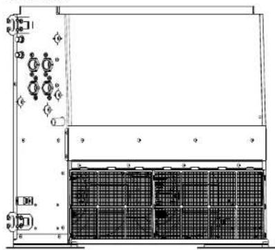
Two technical diagrams showing a vacuum tube connected to a flat plate and a separate flat plate with wires (no text or symbols)4 Set the air filter back to its original position.
text_image
Technical diagram showing a grid-based structure with labeled components and a hand holding a component, possibly indicating a measurement or assembly.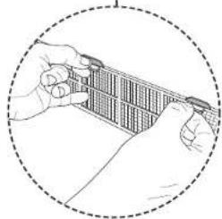
natural_image
Illustration of hands holding a rectangular object with grid lines, enclosed in a dashed circle (no text or symbols)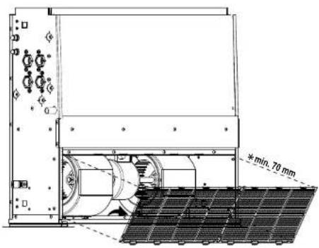
text_image
min. 70 mmFWE03-11D
Fan coil units
3P443944-5E - 2019.09
DAIKIN
Installation manual
8 Technical data
8 Technical data
- A subset of the latest technical data is available on the regional Daikin website (publicly accessible).
- The full set of latest technical data is available on the Daikin Business Portal (authentication required).
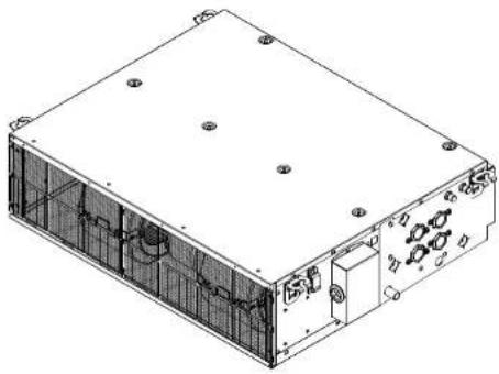
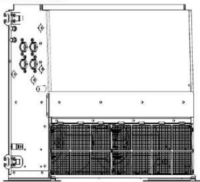
8.1 Dimensions
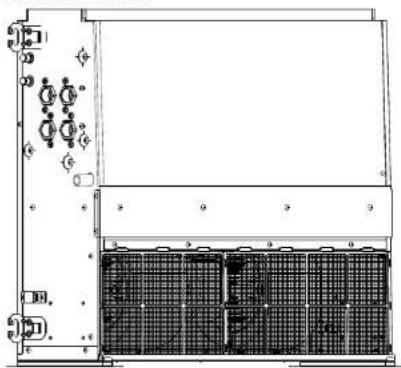
Horizontal outlook
natural_image
Technical line drawing of an electronic device casing with mounting holes and internal components (no text or symbols)Vertical outlook
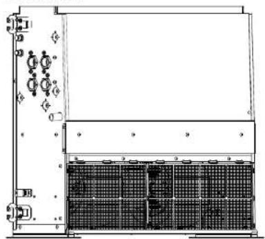
natural_image
Technical line drawing of a server rack with indicator lights and a grid-patterned base (no text or symbols)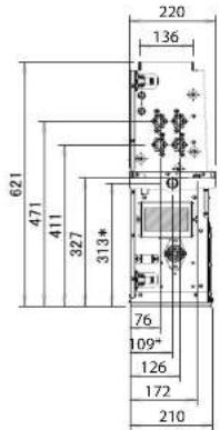
text_image
621 471 411 327 313* 220 136 76 109* 126 172 210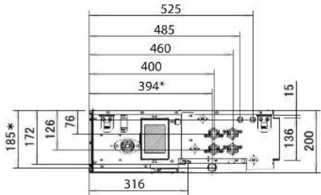
text_image
525 485 460 400 394* 185* 172 126 76 316 136 200 15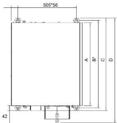
text_image
505*56 A B* C D 42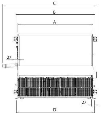
text_image
C B A 27 D 27| Units: mm A B C D | ||||
| FWE03-05 719 757 799 909 | ||||
| FWE06 919 957 999 1109 | ||||
| FWE07-11 1119 1157 1199 1309 |
| Unit: mm | A B C D | |||
| FWE03~05 719 757 909 747 | ||||
| FWE06 919 957 1109 947 | ||||
| FWE07~11 1119 1157 1309 1147 |
Installation manual
DAIKIN
FWE03\~11D
Fan coil units
3P443944-5E - 2019.09
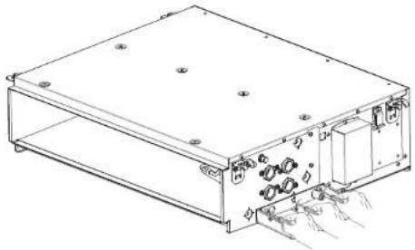
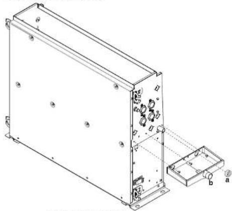
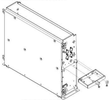
Adjustable drain pan (horizontal)

CAUTION
Make sure to attach the drain socket rubber after installing the additional drain pan. Otherwise condensation on the main unit or water pipes, air filter dirt or drain blockage may cause dripping, resulting in fouling or failure of the object concerned.
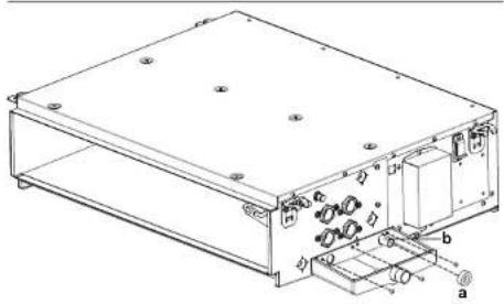
natural_image
Technical line drawing of an electronic device chassis with labeled components (no text or symbols present)a Drain socket rubber
b Additional drain socket
natural_image
Technical line drawing of an electronic device casing with internal components and mounting holes (no text or symbols)Adjustable drain pan (vertical)
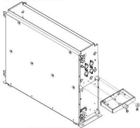
natural_image
Technical line drawing of an electronic device housing with mounting holes and internal components (no text or symbols)a Drain socket rubber
b Additional drain socket
natural_image
Technical line drawing of a rectangular electronic device with mounting holes and internal components (no text or symbols)8 Technical data
8.2 Wiring diagram
On terminal
| English Translation | |
| + | Connection |
| X1M Main terminal | |
| - - - - - - | Field supply |
| PCB | |
| Protective earth | |
| 12 | Earth |
| ::■■■■: | Field wire |
Fan motor cable
WHT White
GRN Green
RED Red
ORG Orange
BRN Brown
YLW Yellow
BLU Blue
GRN/YLW Green/yellow
C1 Capacitor
F1U Fuse
X1M Terminal strip
M Fan motor
8.3 Information requirements for Eco Design
Follow the steps below to consult the Energy Label – Lot 21 data of the unit and outdoor/indoor combinations.
1 Open the following webpage: https://energylabel.daikin.eu/
2 To continue, choose:
- "Continue to Europe" for the international website.
- "Other country" for a country related site.
Result: You are directed to the "Seasonal efficiency" webpage.
3 Under "Eco Design – Ener LOT 21", click "Generate your data".
Result: You are directed to the "Seasonal efficiency (LOT 21)"
webpage.
4 Follow the instructions on the webpage to select the correct unit.
Result: When the selection is done, the LOT 21 datasheet can be viewed as a PDF or a HTML webpage.

INFORMATION
Other documents (e.g. manuals, ...) can also be consulted from the resulting webpage.
Inhaltsverzeichnis
Inhaltsverzeichnis
GEFAHR: STROMSCHLAGGEFAHR
GEFAHR: EXPLOSIONSGEFAHR
GEFAHR: STROMSCHLAGGEFAHR
GEFAHR: STROMSCHLAGGEFAHR
natural_image
Technical line drawing of a mechanical assembly with hands holding components (no text or symbols)natural_image
Technical line drawing of two views of an electronic device casing with ports and connectors (no text or symbols)Modellkennung
text_image
Technical diagram of a device with labeled components and directional arrows indicating movement or flowVertikale Installation
GEFAHR: STROMSCHLAGGEFAHR

WARNUNG
text_image
Technical diagram showing mechanical assembly steps with labeled parts a, b, c, d and directional arrows indicating motion.text_image
Technical diagram showing installation of a fan blade assembly with labeled components and tool tipsnatural_image
Architectural cross-section diagram of a building facade with grid pattern and dimension label (1/100), no readable text or symbols beyond structural lines.text_image
Technical diagram of a mechanical device with labeled components and internal grid structurenatural_image
Technical line drawing of a mechanical enclosure or enclosure frame with internal components and mounting holes (no text or symbols)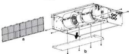
text_image
a btext_image
Technical diagram of an electronic device with labeled components and a grid-patterned inset showing a 3D structure.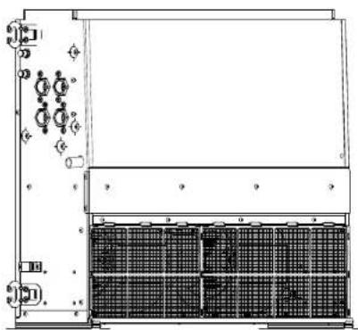
natural_image
Technical line drawing of a mechanical or electrical enclosure with internal components and mounting holes (no text or symbols)a Luftfilter
b Wartungsblende
c Montagesockel
d Schrauben
e Luftfilter
text_image
Technical diagram of an electronic device with labeled components a through fnatural_image
Technical line drawing of a rectangular electronic device with internal components and labeled parts (no text or symbols present)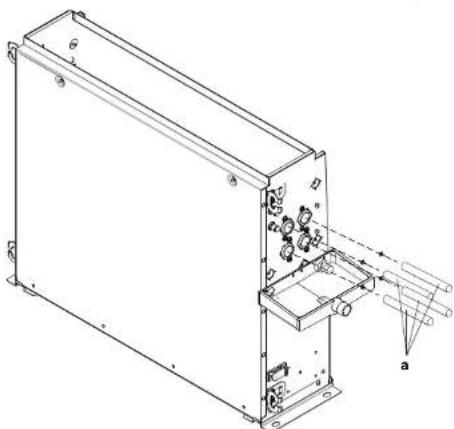
natural_image
Technical line drawing of an electronic device casing with internal components and a labeled section (a), no text or symbols present.a Anschlussrohr
text_image
Technical diagram of an electrical component with labeled parts including a box, coil, and wiring connections1
natural_image
Technical line drawing of a rectangular electronic device with internal components and mounting holes (no text or symbols)natural_image
Diagram showing a device emitting wires from a box, with no visible text or symbolsnatural_image
Technical line drawing of an electronic device rear panel with connectors and wiring (no text or symbols)natural_image
Technical line drawing of an internal mechanical assembly with two cylindrical components (no text or symbols)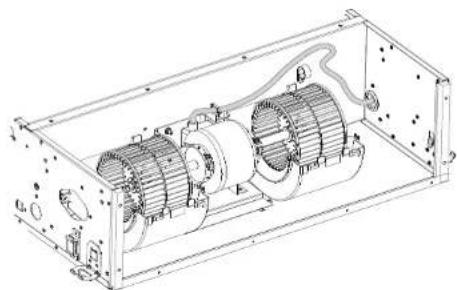
natural_image
Technical line drawing of an internal combustion engine assembly (no text or labels)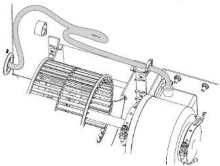
natural_image
Technical line drawing of a mechanical assembly with hoses and components (no text or symbols)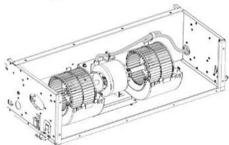
natural_image
Technical line drawing of an internal combustion engine housing with visible components and mounting holes (no text or labels)natural_image
Technical line drawing of an electrical enclosure with two motors and wiring (no text or symbols)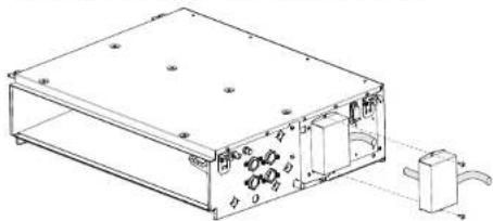
natural_image
Technical line drawing of an electronic device enclosure with internal components and a separate terminal block (no text or symbols)natural_image
Technical line drawing of an electric motor enclosed in a rectangular frame (no text or symbols)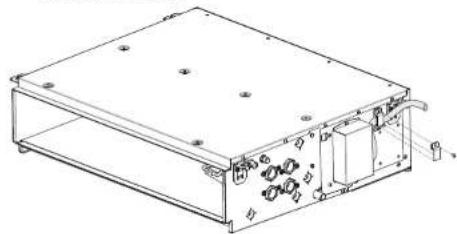
natural_image
Technical line drawing of a rectangular electronic enclosure with internal components and mounting holes (no text or symbols)5 Installation
text_image
Technical diagram showing four stages of a mechanical or electrical component with labeled dimensions (a, b) and cross-sectional views.Vertikale Installation
text_image
Technical diagram showing four sequential steps of a mechanical or structural assembly with labeled components and directional arrows.text_image
Technical diagram of an electronic device with labeled components and a hand pointing to component 'a'
text_image
Exploded view diagram of a solar panel assembly with numbered components for identificationFWE-D Recyclingliste
natural_image
Technical line drawing of a rectangular electronic device with internal components and mounting holes (no text or symbols)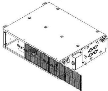
natural_image
Technical line drawing of an electronic device housing with internal components and mounting holes (no text or symbols)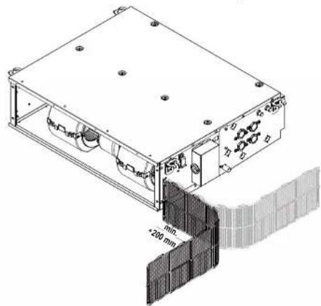
natural_image
Technical line drawing of a mechanical assembly with mounting holes and a 200 mm dimension label (no readable text or symbols beyond measurement)FWE03-11D
Ventilator-Konvektoren 3P443944-5E - 2019.09
text_image
Technical diagram showing assembly steps of a device with labeled components and a 70 mm minimum clearance indicator.natural_image
Illustration of a portable device connected to a flat panel with cables, alongside a separate flat panel with wires (no text or symbols)natural_image
Technical line drawing of a server rack unit with grid panels and control panel (no text or symbols)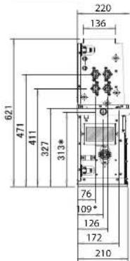
text_image
621 471 411 327 313* 220 136 76 109* 126 172 210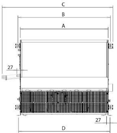
text_image
C B A 27 D 27| Einheiten: mm A B C D | ||||
| FWE03-05 719 757 909 747 | ||||
| FWE06 919 957 1109 947 | ||||
| FWE07-11 1119 1157 1309 1147 | ||||
text_image
Technical diagram of an electronic device with labeled components and mounting pointsnatural_image
Technical line drawing of an electronic device casing with mounting holes and internal components (no text or symbols)natural_image
Technical line drawing of an electronic device housing with mounting holes and internal components (no text or symbols)natural_image
Technical line drawing of an electronic device casing with internal components and a hand inserting a component (no text or symbols present)8 Technische Daten
8.2 Schaltplan
An Klemme
natural_image
Technical line drawing of a mechanical assembly with hands operating it (no text or symbols present)natural_image
Isometric line drawing of a rectangular electronic device with internal components and a black arrow pointing to a small component (no text or symbols)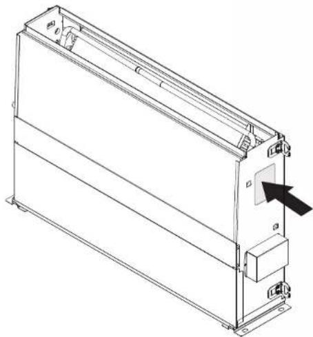
natural_image
Technical line drawing of a rectangular electronic device with mounting brackets and a black arrow pointing to a component (no text or symbols present)Exemple: FW E 03 D A F N 5 V3 — L
text_image
Technical diagram of an electronic device with labeled components and dimensions, including connectors, switches, and a door.Installation verticale
text_image
Technical diagram showing mechanical assembly steps with labeled parts a, b, c, dtext_image
Technical diagram showing installation of a fan blade assembly with labeled components and hand positionstext_image
Technical diagram of a mechanical assembly with labeled components and cross-sectional viewnatural_image
Technical line drawing of a mechanical assembly with labeled components (a and b), showing internal components and structural details (no text or symbols beyond labels)natural_image
Technical line drawing of a server rack with grid and indicator lights (no text or symbols)text_image
Technical diagram of an electronic device with labeled components and internal wiring connectionstext_image
Technical diagram of an electronic device with labeled components and directional arrows indicating motion or flow
natural_image
Technical line drawing of an electronic device casing with internal components and mounting holes (no text or symbols)a Tuyau de raccordement
text_image
Technical diagram of an electrical enclosure with labeled components including a base, fuse, and heating element.natural_image
Technical line drawing of a rectangular electronic device with internal components and mounting holes (no text or symbols)natural_image
Diagram of a cable or wire connector inside an enclosure, showing internal wiring and external connections (no text or symbols)natural_image
Pure electrical circuit lines without any symbolsnatural_image
Technical line drawing of an internal mechanical assembly with two cylindrical components (no text or symbols)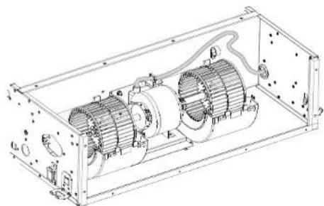
natural_image
Technical line drawing of an internal combustion engine assembly (no text or labels)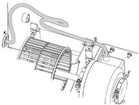
natural_image
Technical line drawing of a mechanical assembly with hoses and components (no text or symbols)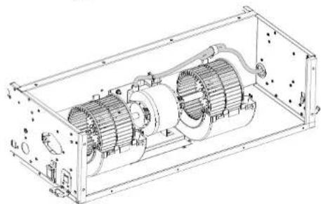
natural_image
Technical line drawing of an internal combustion engine housing with visible components and mounting holes (no text or labels)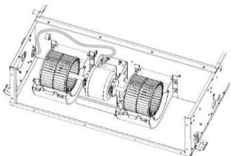
natural_image
Technical line drawing of an electrical enclosure with two motors and wiring (no text or symbols)natural_image
Technical line drawing of a rectangular electronic device with internal components and a separate terminal block (no text or symbols)natural_image
Technical line drawing of an electric motor enclosed in a rectangular frame (no text or symbols)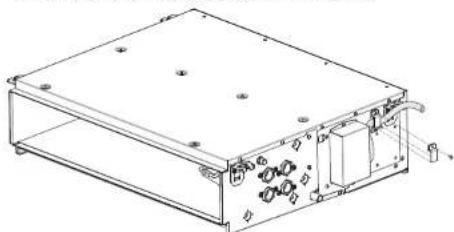
natural_image
Technical line drawing of a rectangular electronic device with internal components and mounting holes (no text or symbols)5 Installation
text_image
Technical diagram showing two views of a device with labeled components and dimensions, including a cable and wire connection.Installation verticale
text_image
a b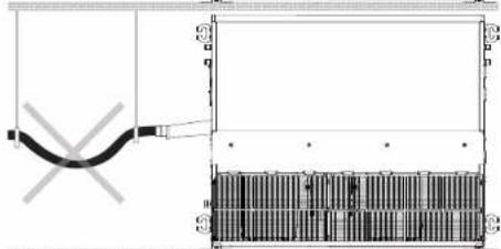
natural_image
Pure electrical circuit lines without any symbols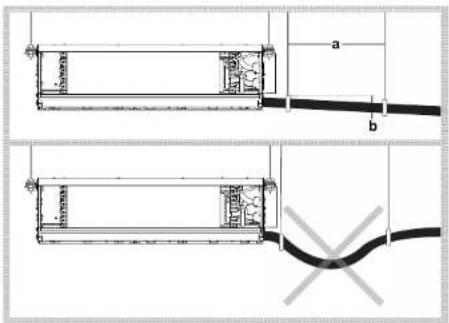
text_image
a b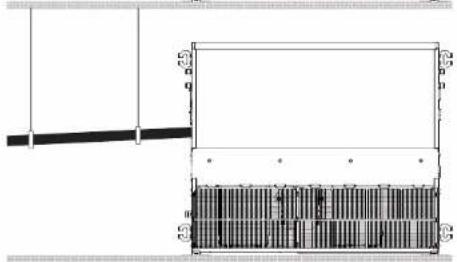
natural_image
Pure architectural or mechanical diagram showing a beam and column structure without any text, numbers, or symbols.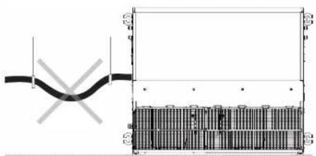
text_image
Technical diagram showing a pipe connection with cross-sectional view and labeled componentsnatural_image
Technical line drawing of an electronic device chassis with labeled components (a and b), no readable text or symbols beyond labelsnatural_image
Pure schematic diagram of a laboratory apparatus with no text, numbers, or symbolstext_image
Exploded view diagram of a solar panel assembly with numbered components for identificationnatural_image
Technical line drawing of an electronic device casing with internal components and mounting holes (no text or symbols)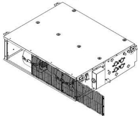
natural_image
Technical line drawing of an electronic device housing with internal components and mounting holes (no text or symbols)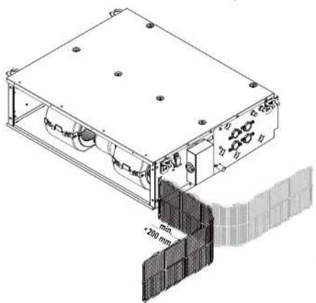
natural_image
Technical line drawing of a mechanical device with mounting holes and a wall-mounted panel (no text or symbols)natural_image
Technical line drawing of a mechanical or electrical enclosure with internal grid structure (no text or symbols)natural_image
Two technical illustrations of a portable device connected to a flat panel and a separate flat panel with wires (no text or symbols)text_image
Technical diagram showing a grid-based device with labeled components and a magnified view of its internal structure.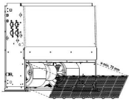
text_image
min. 70 mmFWE03-11D
Ventilo-convecteurs
3P443944-5E - 2019.09
DAIKIN
natural_image
Technical line drawing of an electronic device casing with internal components and mounting holes (no text or symbols)Disposition verticale
natural_image
Technical line drawing of a mechanical or electrical enclosure with internal components and mounting holes (no text or symbols)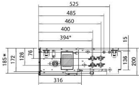
text_image
525 485 460 400 394* 185* 172 126 76 15 136 200 316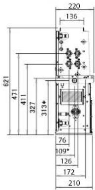
text_image
621 471 411 327 313* 220 136 76 109* 126 172 210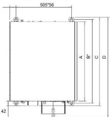
natural_image
Technical line drawing of an electronic device housing with mounting holes and internal components (no text or symbols)natural_image
Technical line drawing of an electronic device casing with internal components and mounting holes (no text or symbols)natural_image
Technical line drawing of an electronic device housing with mounting holes and internal components (no text or symbols)natural_image
Technical line drawing of an electronic device casing with internal components and a hand inserting a cable (no text or symbols)WAARSCHUWING: ONTVLAMBAAR MATERIAAL

VOORZICHTIG
natural_image
Technical line drawing of a mechanical assembly with hands and labeled components (no readable text or symbols)natural_image
Technical line drawings of an electronic device casing with internal components and mounting points (no text or symbols)Modelidentificatie
text_image
Technical diagram of a device layout with labeled components and directional arrows indicating movement or assembly.Verticale installatie
text_image
Technical diagram illustrating the assembly of a bolt with labeled parts (a, b, c, d) and directional arrows indicating motion or assembly.text_image
Technical diagram of a mechanical or electrical enclosure with labeled components and internal grid structuretext_image
Technical diagram of an industrial machine with labeled components and structural detailstext_image
Technical diagram of an air conditioning unit with labeled components and a grid-patterned inset showing a 3D model.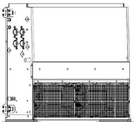
natural_image
Technical line drawing of a mechanical or electrical enclosure with grid panels and mounting brackets (no text or symbols)text_image
Technical diagram of an electronic device with labeled components and internal wiring connectionstext_image
Technical diagram of an electronic device with labeled components and directional arrows indicating flow or movement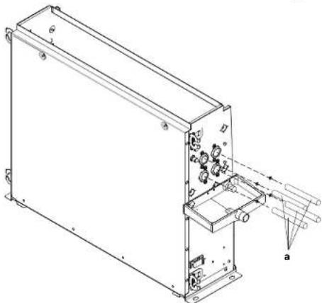
natural_image
Technical line drawing of an electronic device with internal components and labeled parts (a, b, c), no readable text or symbols present.a Verbindingsleiding
text_image
Technical diagram of an electrical component with labeled parts including a transformer, coil, and mounting bracketa Deksel klemmenstrook
b Sticker
c Voedingskabel
d Klemmenstrook
e Aardingskabel
f Kabelklen
natural_image
Technical line drawing of a rectangular electronic device with internal components and mounting holes (no text or symbols)2 Maak de kabels van de ventilatormotor los van de kabelklemmen.
natural_image
Diagram of a device with wires and connectors, showing airflow direction (no text or symbols)natural_image
Technical line drawing of an electrical connector panel with wiring and terminal blocks (no text or symbols)5 Installatie
natural_image
Technical line drawing of an electric motor assembly inside a frame, showing internal components and mounting brackets (no text or labels)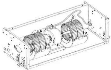
natural_image
Technical line drawing of an electric motor assembly inside a rectangular frame (no text or labels)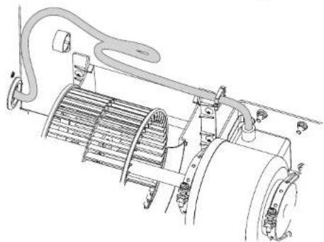
natural_image
Technical line drawing of an electric motor with cooling fan and wiring (no text or symbols)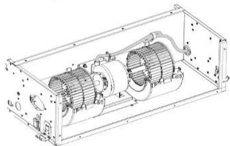
natural_image
Technical line drawing of an internal combustion engine housing with visible components and mounting holes (no text or labels)natural_image
Technical line drawing of an electric motor assembly inside a housing frame (no text or labels)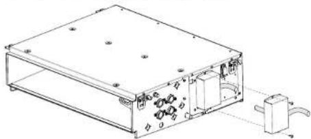
natural_image
Technical line drawing of a rectangular electronic device with internal components and a separate connector (no text or symbols)natural_image
Technical line drawing of an internal combustion engine housing with visible motors and wiring (no text or labels)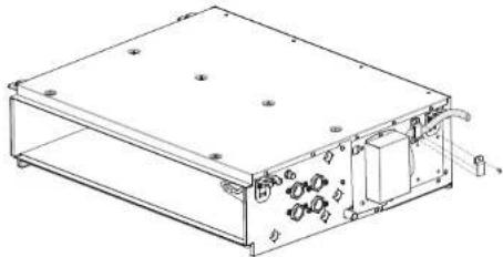
natural_image
Technical line drawing of a rectangular electronic device with internal components and mounting holes (no text or symbols)5 Installatie
text_image
Technical diagram showing four stages of a mechanical or electrical component with labeled dimensions (a, b) and cross-sectional views.Verticale installatie
text_image
Technical diagram showing four sequential steps of a structural or mechanical assembly with labeled components and dimensions.natural_image
Technical line drawing of an electronic device chassis with labeled components (a and b), no readable text or symbols beyond labels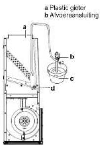
text_image
a Plastic gieter b Afooraansluiting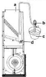
text_image
a b c dnatural_image
Simple line drawing of a laboratory apparatus with a beaker, tubing, and a beaker with liquid (no text or symbols)text_image
Exploded view diagram of a solar panel assembly with numbered components for identificationnatural_image
Technical line drawing of a mechanical or electrical enclosure with internal grid structure (no text or symbols)natural_image
Diagram showing a motor connected to a flat panel and a separate flat panel with wires (no text or symbols)text_image
Technical diagram showing a grid-based device with labeled components and a magnified view of its internal structure.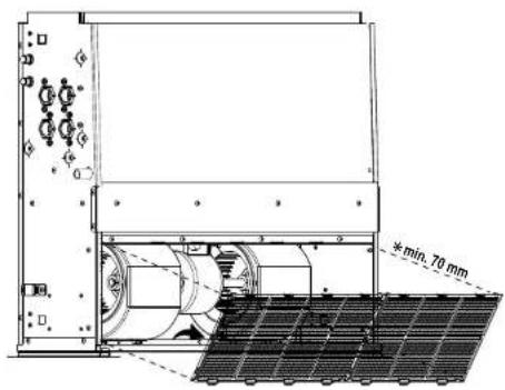
text_image
min. 70 mmFWE03-11D
Ventilo-convectoren
3P443944-5E - 2019.09
DAIKIN
Montagehandleiding
natural_image
Technical line drawing of an electronic device casing with internal components and mounting holes (no text or symbols)Verticaal overzicht
natural_image
Technical line drawing of a server rack unit with indicator lights and grid panels (no text or symbols)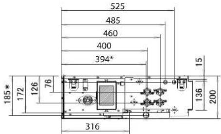
text_image
525 485 460 400 394* 185* 172 126 76 15 136 200 316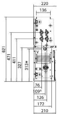
text_image
621 471 411 327 313* 220 136 76 109° 126 172 210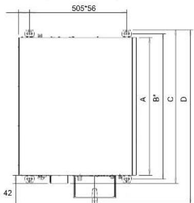
text_image
505*56 A B* C D 42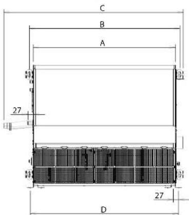
text_image
C B A 27 D 27| Eenheid: mm A B C D | ||||
| FWE03-05 719 757 799 909 | ||||
| FWE06 919 957 999 1109 | ||||
| FWE07-11 1119 1157 1199 1309 |
| Eenheid: mm A B C D | ||||
| FWE03~05 719 757 909 747 | ||||
| FWE06 919 957 1109 947 | ||||
| FWE07~11 1119 1157 1309 1147 |
natural_image
Technical line drawing of a rectangular electronic device with internal components and mounting holes (no text or symbols)natural_image
Technical line drawing of a rectangular electronic device with mounting holes and internal components (no text or symbols)Regelbare lekbak (verticaal)
natural_image
Technical line drawing of an electronic device housing with mounting holes and internal components (no text or symbols)natural_image
Technical line drawing of an electronic device casing with internal components and a hand inserting a cable (no text or symbols)natural_image
Technical line drawing of a mechanical assembly with hands and labeled components (no text or symbols)natural_image
Technical line drawing of two views of an electronic device casing with ports and connectors (no text or symbols)text_image
Technical diagram of a device layout with labeled components and directional arrows indicating movement or assembly.text_image
Technical diagram showing mechanical assembly steps with labeled parts a, b, c, d and directional arrows indicating motion or transformation.text_image
Technical diagram showing installation of a fan blade assembly with labeled components and tool tipsnatural_image
Architectural cross-section diagram of a building facade with grid pattern and dimension label (1/100), no readable text or symbols beyond structural lines.text_image
Technical diagram of a mechanical or electrical device with labeled components and internal grid structurenatural_image
Technical line drawing of an industrial enclosure or enclosure with internal components and mounting brackets (no text or symbols)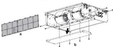
text_image
a btext_image
Technical diagram of a mechanical assembly with labeled components and cross-sectional view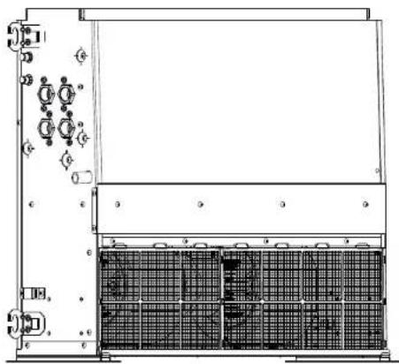
natural_image
Technical line drawing of a server rack unit with grid panels and indicator lights (no text or symbols)text_image
Technical diagram of an electronic device with labeled components and internal wiring connectionstext_image
Technical diagram of an electronic device with labeled components and directional arrows indicating motion or flow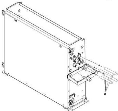
natural_image
Technical line drawing of an electronic device casing with internal components and mounting brackets (no text or symbols)text_image
Technical diagram of an electrical switchgear assembly with labeled componentsnatural_image
Technical line drawing of a rectangular electronic device with internal components and mounting holes (no text or symbols)natural_image
Diagram of a device with wires and connectors inside a box, showing airflow direction (no text or symbols)natural_image
Technical line drawing of an electrical connector panel with wiring and terminal blocks (no text or symbols)text_image
Technical diagram showing two views of a cylindrical device with labeled dimensions (a and b) and internal components, plus a close-up of the cable.natural_image
Pure electrical circuit lines without any symbols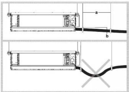
text_image
Technical diagram showing two mechanical assembly configurations with labeled dimensions a and b, and a cross symbol indicating a defect or failure.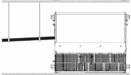
natural_image
Pure architectural or mechanical diagram showing a beam and a rectangular structure with internal vertical divisions (no text or symbols)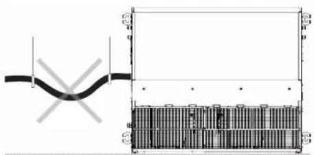
natural_image
Pure technical diagram showing a pipe connection and a grid layout with no text or symbolsnatural_image
Technical line drawing of an electronic device chassis with labeled components (a and b), no readable text or symbols beyond labelsnatural_image
Simple line drawing of a laboratory apparatus with a beaker, tubing, and a test tube (no text or symbols)text_image
Exploded view diagram of an electronic device with numbered components for identificationnatural_image
Technical line drawing of a rectangular electronic device with internal components and mounting holes (no text or symbols)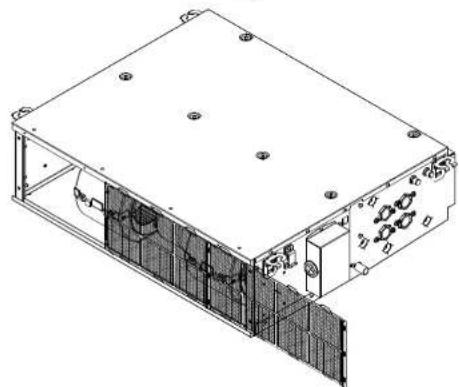
natural_image
Technical line drawing of an electronic device housing with internal components and mounting holes (no text or symbols)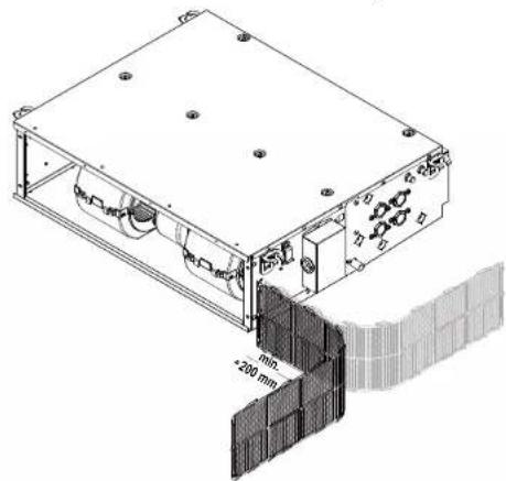
natural_image
Technical line drawing of a mechanical assembly with mounting holes and a 200 mm dimension label (no readable text or symbols beyond measurement)FWE03-11D
Unidades fan coil
3P443944-5E - 2019.09
natural_image
Technical line drawing of a mechanical or electrical enclosure with internal grid structure (no text or symbols)natural_image
Technical line drawing of a simple electrical component with a motor and cable, next to a flat panel (no text or symbols)text_image
Technical diagram showing a grid-based device with labeled components and a magnified view of its internal structure.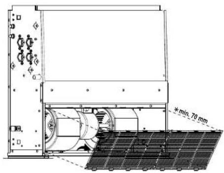
text_image
min. 70 mm8 Datos técnicos
8 Datos técnicos
natural_image
Technical line drawing of an electronic device casing with mounting holes and internal components (no text or symbols)Vista vertical
natural_image
Technical line drawing of a mechanical or electrical enclosure with internal components and no visible text or symbols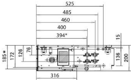
text_image
525 485 460 400 394* 185* 172 126 76 316 136 200 15
text_image
621 471 411 327 313* 220 136 76 109° 126 172 210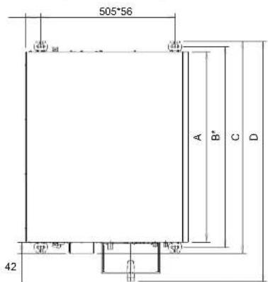
text_image
505*56 A B* C D 42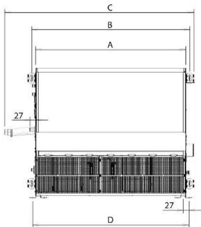
text_image
C B A 27 D 27| Unidad: mm A B C D | ||||
| FWE03-05 719 757 799 909 | ||||
| FWE06 919 957 999 1109 | ||||
| FWE07-11 1119 1157 1199 1309 |
| Unidad: mm A B C D | ||||
| FWE03-05 719 757 909 747 | ||||
| FWE06 919 957 1109 947 | ||||
| FWE07-11 1119 1157 1309 1147 |
natural_image
Technical line drawing of a rectangular electronic device with internal components and mounting holes (no text or symbols)natural_image
Technical line drawing of an electronic device casing with internal components and mounting holes (no text or symbols)Bandeja de drenaje ajustable (vertical)
natural_image
Technical line drawing of an electronic device housing with mounting holes and internal components (no text or symbols)natural_image
Technical line drawing of an electronic device casing with internal components and a hand inserting a component (no text or symbols visible)8 Datos técnicos
text_image
Technical diagram showing hands operating a rectangular device with labeled dimensions and componentsnatural_image
Isometric line drawing of a rectangular electronic device with labeled ports (a) and a small internal component (a), no text or symbols present.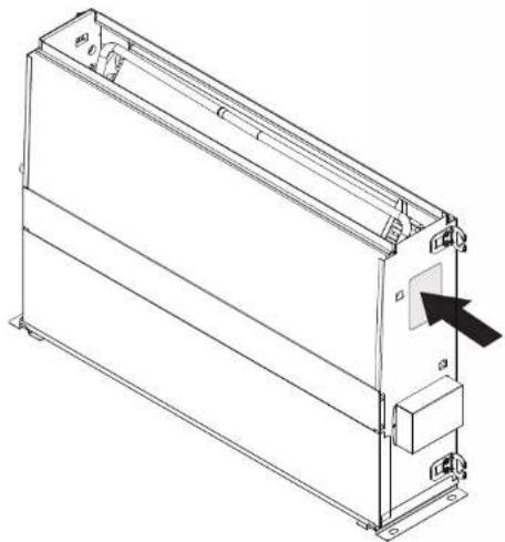
natural_image
Technical line drawing of a rectangular electronic device with mounting brackets and a black arrow pointing to a component (no text or symbols present)text_image
Technical diagram showing mechanical assembly steps with labeled parts a, b, c, and dnatural_image
Technical line drawing of a rectangular electronic device with labeled components (a and b), no readable text or symbols present.text_image
Technical diagram showing installation of a fan blade assembly with labeled components and tool tipsnatural_image
Architectural cross-section diagram of a building facade with grid pattern and dimension label (1/100), no readable text or symbols beyond structural lines.text_image
Technical diagram of a mechanical assembly with labeled components and cross-sectional viewnatural_image
Technical line drawing of a mechanical assembly with labeled components (a and b), showing internal components and structural details (no text or symbols beyond labels)natural_image
Technical line drawing of a server rack with indicator lights and grid panels (no text or symbols)text_image
Technical diagram of an electronic device with labeled components and internal wiring connectionsnatural_image
Technical line drawing of a rectangular electronic device with internal components and directional arrows indicating motion (no text or symbols)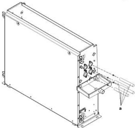
natural_image
Technical line drawing of an electronic device casing with internal components and mounting holes (no text or symbols)text_image
Technical diagram of an electrical component with labeled parts including a box, coil, and mounting bracketnatural_image
Technical line drawing of a rectangular electronic device with internal components and mounting holes (no text or symbols)natural_image
Diagram of a device with multiple wires radiating from a central component, showing flow direction (no text or symbols)natural_image
Technical line drawing of an electrical connector panel with wiring and terminal blocks (no text or symbols)text_image
Technical diagram showing two views of a device with labeled components and dimensions, including a cable and wire connection.text_image
a b q (5)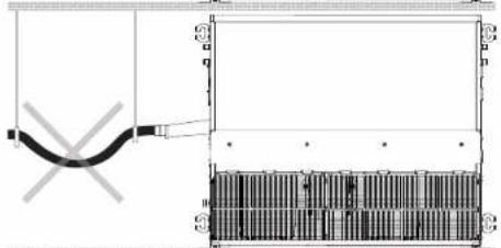
natural_image
Pure electrical circuit lines without any symbols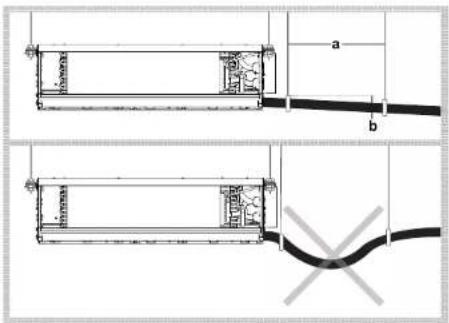
text_image
Technical diagram showing two mechanical assembly configurations with labeled dimensions a and b, and a close-up of a wire being welded.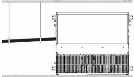
natural_image
Pure architectural or engineering diagram showing a beam and column structure without any text, numbers, or symbols.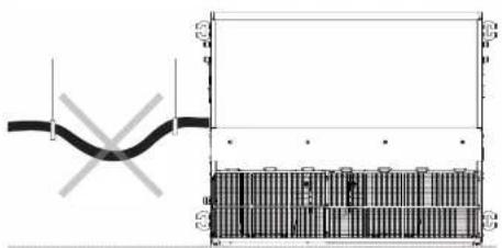
text_image
Technical diagram showing a pipe connection with cross-sectional view and labeled componentsnatural_image
Technical line drawing of an electronic device chassis with labeled components (a and b), no readable text or symbols present.text_image
Exploded view diagram of a solar panel assembly with numbered components for identificationnatural_image
Isometric technical drawing of a rectangular electronic device with internal components and mounting holes (no text or symbols)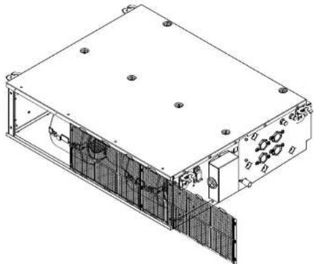
natural_image
Technical line drawing of an electronic device housing with internal components and mounting holes (no text or symbols)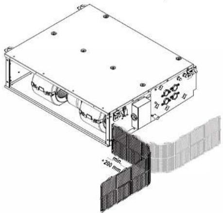
natural_image
Technical line drawing of a mechanical device with mounting holes and a wall-mounted panel (no text or symbols)natural_image
Technical line drawing of a mechanical or electrical enclosure with internal grid structure (no text or symbols)natural_image
Technical line drawing of a simple electrical component with a motor and cable, next to a flat panel (no text or symbols)text_image
Technical diagram showing a grid-based device with labeled components and a magnified view of its internal structure.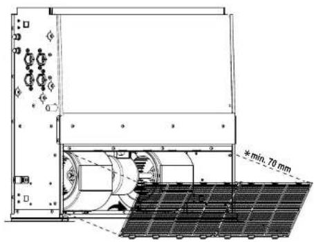
text_image
min. 70 mmFWE03-11D
Ventilconvettori
3P443944-5E - 2019.09
DAIKIN
natural_image
Technical line drawing of an electronic device casing with mounting holes and internal components (no text or symbols)Vista verticale
natural_image
Technical line drawing of a server rack with indicator lights and grid panels (no text or symbols)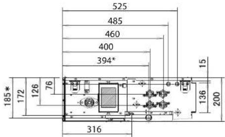
text_image
525 485 460 400 394* 185* 172 126 76 316 136 200 15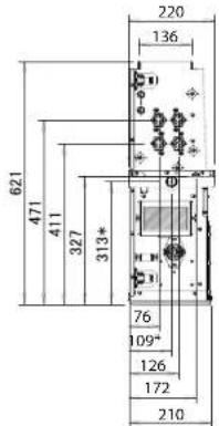
text_image
621 471 411 327 313* 220 136 76 109* 126 172 210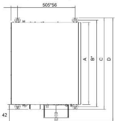
text_image
Technical diagram of an electronic device with labeled components and mounting pointsnatural_image
Technical line drawing of an electronic device casing with internal components and mounting holes (no text or symbols)natural_image
Technical line drawing of an electronic device housing with mounting holes and internal components (no text or symbols)natural_image
Technical line drawing of an electronic device casing with internal components and a hand inserting a cable (no text or symbols)8 Dati tecnici
natural_image
Technical line drawing of a mechanical assembly with hands and labeled components (no text or symbols)natural_image
Isometric line drawing of a rectangular electronic device with labeled ports and an arrow pointing to a small component (no text or symbols present)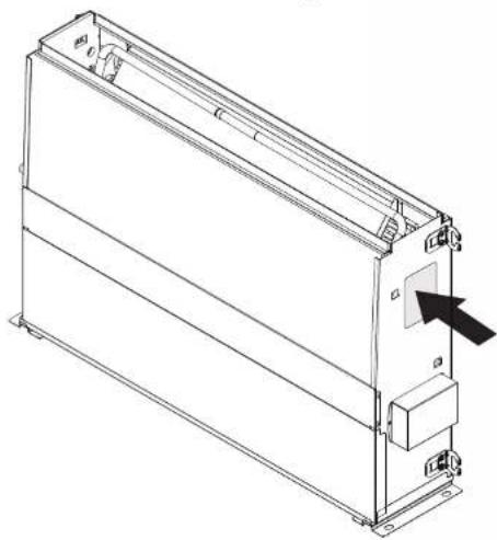
natural_image
Technical line drawing of a rectangular electronic device with mounting brackets and a black arrow pointing to a component (no text or symbols present)Στοιχεία μοντέλου
natural_image
Technical diagram of an electronic device casing with ports, connectors, and a central panel (no readable text or symbols)natural_image
Technical schematic of a device casing with internal components and directional arrows (no text or labels)text_image
Technical diagram showing mechanical assembly with labeled parts a, b, c, d and directional arrows indicating motion or transformation.text_image
Technical diagram showing installation of a fan blade assembly with labeled components and hand positionstext_image
Technical diagram of a mechanical or electrical device with labeled components and internal grid structuretext_image
Technical diagram of a mechanical assembly with labeled components and cross-sectional viewstext_image
Technical diagram of a mechanical assembly with labeled components and a grid-patterned inset showing a 3D structure.5 Εγκατάσταση
natural_image
Technical line drawing of a mechanical or electrical enclosure with grid panels and control panel (no text or symbols)text_image
Technical diagram of an electronic device with labeled components a through ftext_image
Technical diagram of an electronic device with labeled components and light path indicators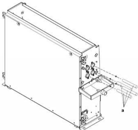
natural_image
Technical line drawing of an electronic device casing with internal components and mounting brackets (no text or symbols)a Σωλήνας σύνδεοης
text_image
Technical diagram of an electrical component with labeled parts including a box, cable, and terminal blocksnatural_image
Technical line drawing of an electronic device enclosure with internal components and a separate unit (no text or symbols)natural_image
Diagram of a cable being inserted into a device, showing internal wiring and discharge (no text or labels)natural_image
Pure electrical circuit lines without any symbolsnatural_image
Technical line drawing of an internal mechanical assembly with two cylindrical components (no text or symbols)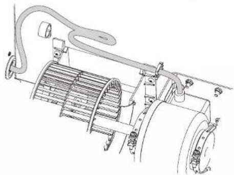
natural_image
Technical line drawing of a mechanical assembly with no visible text or symbols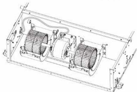
natural_image
Technical line drawing of an electrical enclosure with two motors and wiring (no text or symbols)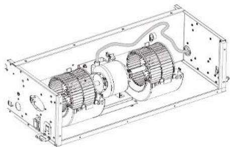
natural_image
Technical line drawing of an electric motor enclosed in a rectangular frame (no text or symbols)5 Εγκατάσταση
natural_image
Technical line drawing of an internal combustion engine unit with visible stator, rotor, and housing (no text or labels)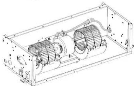
natural_image
Technical line drawing of an internal combustion engine housing with visible components and mounting holes (no text or labels)natural_image
Technical line drawing of an electronic device casing with mounting holes and a separate connector (no text or symbols)natural_image
Technical line drawing of a rectangular electronic device with internal components and mounting holes (no text or symbols)text_image
Technical diagram showing two views of a cylindrical device with labeled dimensions (a and b) and internal components, plus a close-up of a cable.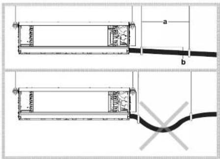
text_image
a b a bnatural_image
Technical line drawing of an electronic device casing with labeled components (a and b), no readable text or symbols beyond labelstext_image
Technical diagram of a laboratory apparatus with labeled components and a piping systemtext_image
Exploded view diagram of a solar panel assembly with numbered components for identificationnatural_image
Technical line drawing of a rectangular electronic device with internal components and mounting holes (no text or symbols)natural_image
Technical line drawing of a rectangular electronic device with internal components and mounting holes (no text or symbols)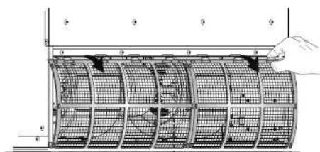
text_image
Technical diagram showing a grid-patterned structure with labeled components and a hand holding the top section.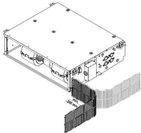
natural_image
Technical line drawing of a mechanical device with a 200 mm height annotation and internal components (no readable text or symbols)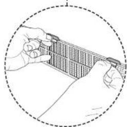
natural_image
Illustration of hands holding a grid-like object within a dashed circle (no text or symbols)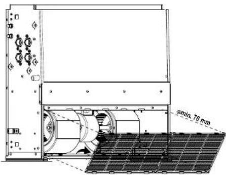
text_image
5min. 70 mmnatural_image
Technical line drawing of a mechanical or electrical enclosure with internal grid structure (no text or symbols)natural_image
Two technical diagrams showing a vacuum cleaner connected to a grid-mounted device and a separate panel with a cable (no text or symbols present)natural_image
Technical line drawing of an electronic device casing with mounting holes and internal components (no text or symbols)Κατακόρυφη άποψη
natural_image
Technical line drawing of a mechanical or electrical enclosure with internal components and mounting holes (no text or symbols)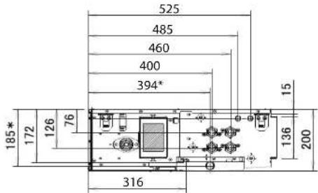
text_image
525 485 460 400 394* 185* 172 126 76 316 136 200 15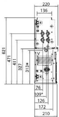
text_image
621 471 411 327 313* 220 136 76 109* 126 172 210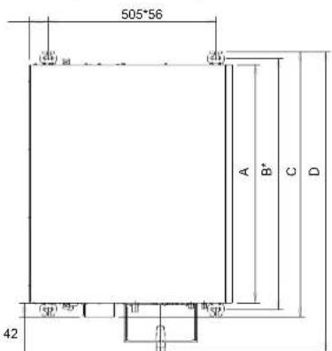
text_image
Technical diagram of an electronic device with labeled components and mounting pointsnatural_image
Technical line drawing of an electronic device casing with mounting holes and internal components (no text or symbols)natural_image
Technical line drawing of an electronic device housing with mounting holes and internal components (no text or symbols)natural_image
Technical line drawing of an electronic device casing with internal components and a hand inserting a cable (no text or symbols)natural_image
Technical line drawing of a mechanical assembly with hands and dimension annotations (no readable text or symbols)natural_image
Isometric line drawing of a rectangular electronic device with labeled ports (a) and a small internal component (a), no text or symbols present.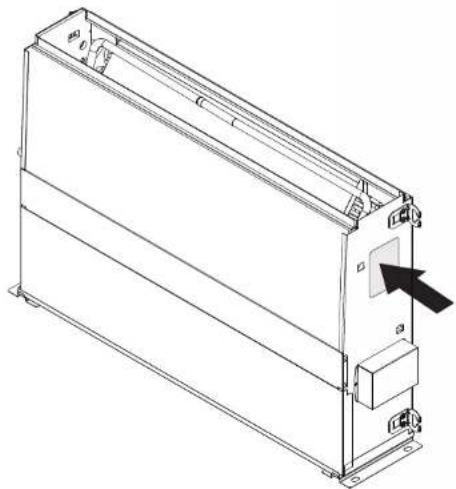
natural_image
Technical line drawing of a rectangular electronic device with mounting brackets and a black arrow pointing to a component (no text or symbols present)text_image
Technical diagram of an electronic device with labeled components and dimensions, including connectors, switches, and a door.Instalação vertical
text_image
Technical diagram showing mechanical assembly steps with labeled parts a, b, c, and dnatural_image
Technical line drawing of a rectangular electronic device with labeled components (a and b), no readable text or symbols beyond labelstext_image
Technical diagram showing installation of a fan blade assembly with labeled components and tool tipsnatural_image
Architectural cross-section diagram of a building facade with grid pattern and dimension label (1/100), no readable text or symbols beyond structural lines.text_image
Technical diagram of a mechanical device with labeled components and internal grid structurenatural_image
Technical line drawing of an internal air duct system with no visible text or symbols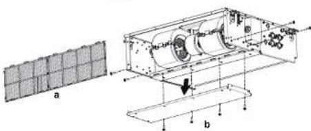
text_image
a btext_image
Technical diagram of a mechanical assembly with labeled components and a grid-patterned inset showing a 3D panel.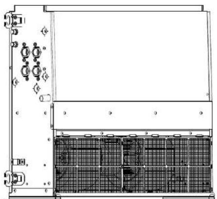
natural_image
Technical line drawing of a mechanical or electrical enclosure with grid panels and mounting brackets (no text or symbols)text_image
Technical diagram of an electronic device with labeled components a through fnatural_image
Technical line drawing of a rectangular electronic device with internal components and labeled parts (no text or symbols present)
text_image
Technical diagram of an electronic device with labeled components and directional arrows indicating assembly or movement.a Tubo de ligação
text_image
Technical diagram of an electrical switch assembly with labeled componentsnatural_image
Technical line drawing of a rectangular electronic enclosure with internal components and mounting holes (no text or symbols)5 Instalação
natural_image
Diagram of a cable or wire penetration device with exposed wires and connectors, showing no text or symbols.natural_image
Technical line drawing of a mechanical assembly with hoses and components (no text or symbols)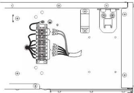
text_image
Technical diagram showing wiring connections between a device panel with labeled terminals and connectorsnatural_image
Technical line drawing of an electrical enclosure with two motors and wiring (no text or symbols)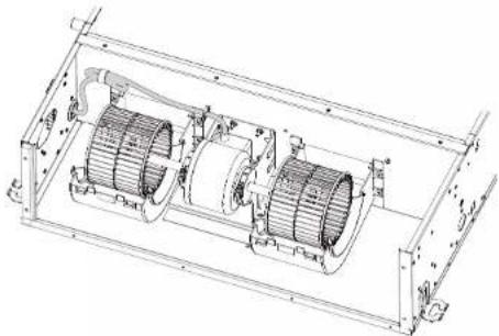
natural_image
Technical line drawing of a mechanical assembly with two cylindrical components and housing (no text or symbols)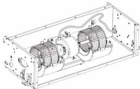
natural_image
Technical line drawing of an electric motor enclosed in a rectangular frame, showing internal components and wiring (no text or labels)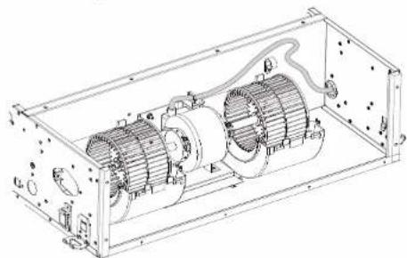
natural_image
Technical line drawing of an internal combustion engine unit (no text or labels visible)5 Instalação
natural_image
Technical line drawing of an internal combustion engine assembly (no text or labels)text_image
Technical diagram showing two electrical or mechanical components with labeled dimensions a and b, including internal structures and a cross symbol indicating a fault or failure.Instalação vertical
natural_image
Technical line drawing of a rectangular electronic device with mounting holes and internal components (no text or symbols)natural_image
Pure technical diagram showing a mechanical component and a grid-patterned structure without any text or symbols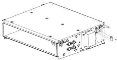
natural_image
Technical line drawing of a rectangular electronic device with internal components and mounting holes (no text or symbols)text_image
Technical diagram showing two mechanical components with labeled dimensions a and b, including internal structure and a wire connection.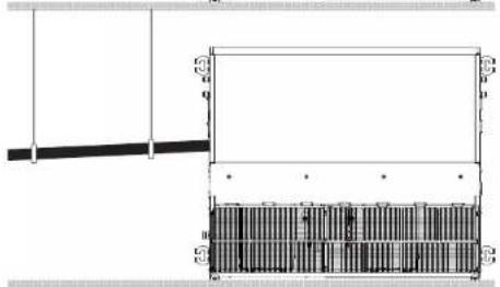
natural_image
Pure architectural or engineering diagram showing a beam and a rectangular structure with internal vertical divisions (no text or symbols)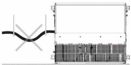
natural_image
Pure electrical circuit lines without any symbolsnatural_image
Technical line drawing of an electronic device chassis with labeled components (a and b), no readable text or symbols present.natural_image
Pure schematic diagram of a laboratory apparatus with no text, numbers, or symbolstext_image
Exploded view diagram of a solar panel assembly with numbered components for identificationnatural_image
Technical line drawing of an electronic device casing with internal components and mounting holes (no text or symbols)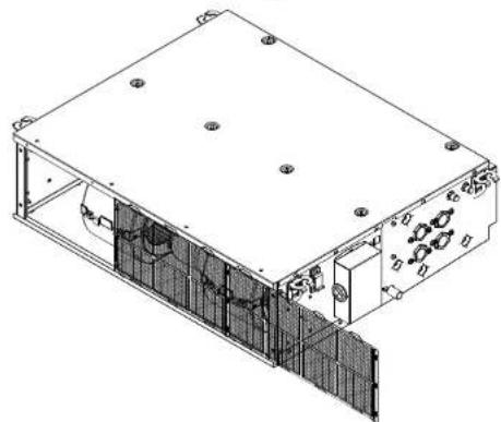
natural_image
Technical line drawing of an electronic device housing with internal components and mounting holes (no text or symbols)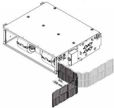
natural_image
Technical line drawing of a mechanical device with mounting holes and a wall section showing a 200 mm dimension (no text or symbols present)natural_image
Technical line drawing of a mechanical or electrical enclosure with internal grid structure (no text or symbols)natural_image
Two technical illustrations of a portable electronic device connected to a flat panel and a separate flat panel with wires (no text or symbols)text_image
Technical diagram showing a grid-based device with labeled components and a magnified view of its internal structure.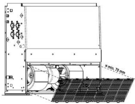
text_image
min. 70 mm8 Dados técnicos
8 Dados técnicos
natural_image
Technical line drawing of an electronic device casing with internal components and mounting holes (no text or symbols)Vista vertical
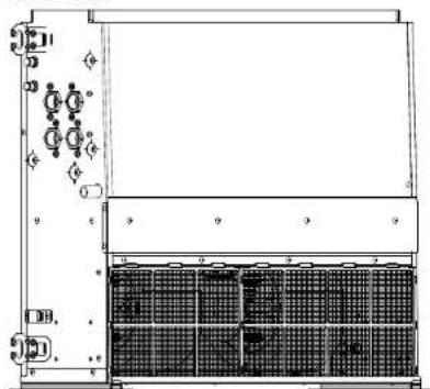
natural_image
Technical line drawing of a server rack with indicator lights and grid panels (no text or symbols)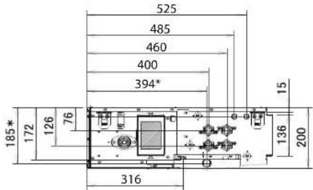
text_image
525 485 460 400 394* 185* 172 126 76 316 136 200 15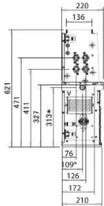
text_image
621 471 411 327 313* 220 136 76 09° 126 172 210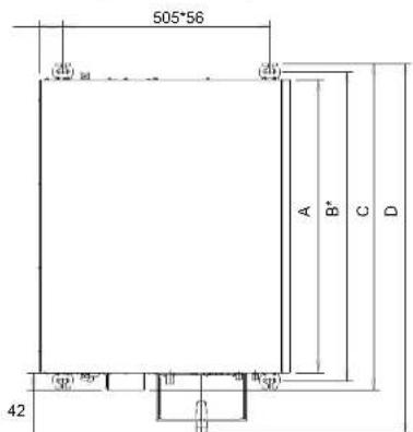
text_image
505*56 (4) (4) A B* C D (4) (4) (4) (4) (4) (4)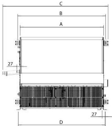
text_image
C B A 27 D 27| Unidades: mm A B C D | ||||
| FWE03-05 719 757 799 909 | ||||
| FWE06 919 957 999 1109 | ||||
| FWE07-11 1119 1157 1199 1309 |
| Unidade: mm A B C D | ||||
| FWE03-05 719 757 909 747 | ||||
| FWE06 919 957 1109 947 | ||||
| FWE07-11 1119 1157 1309 1147 |
natural_image
Technical line drawing of a rectangular electronic device with internal components and mounting holes (no text or symbols)a Borracha do encaixe de drenagem
b Encaixe de drenagem adicional
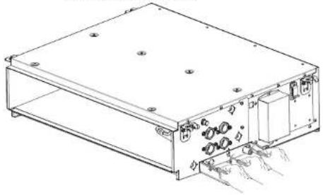
natural_image
Technical line drawing of an electronic device casing with internal components and mounting holes (no text or symbols)natural_image
Technical line drawing of an electronic device housing with mounting holes and internal components (no text or symbols)a Borracha do encaixe de drenagem
b Encaixe de drenagem adicional
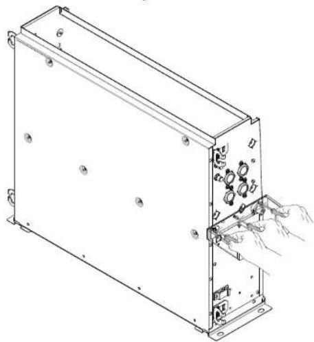
natural_image
Technical line drawing of an electronic device casing with internal components and a hand inserting a cable (no text or symbols)8 Dados técnicos
natural_image
Technical line drawing of a mechanical assembly with hands holding parts (no text or symbols)natural_image
Technical line drawings of an electronic device casing with internal components and mounting points (no text or symbols)text_image
Technical diagram showing a mechanical or electrical component layout with labeled parts and dimension annotation ≥150Вертикальный монтаж
text_image
Technical diagram showing mechanical assembly steps with labeled parts a, b, c, d and directional arrows indicating motion or transformation.natural_image
Technical line drawing of a rectangular electronic device with labeled components (a, b), no readable text or symbols present.text_image
Technical diagram showing installation of a fan blade assembly with labeled components and hand positionsnatural_image
Architectural cross-section diagram of a building facade with grid patterns and dimension标注 (no text or symbols)text_image
Technical diagram of a mechanical or electrical device with labeled components and internal grid structurenatural_image
Technical line drawing of an industrial air duct system with fan and housing (no text or symbols)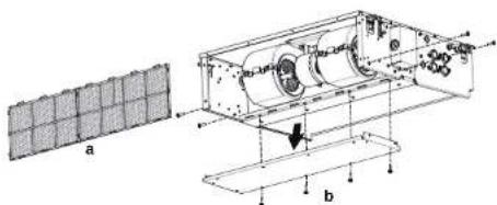
text_image
a btext_image
Technical diagram of a mechanical assembly with labeled components and cross-sectional view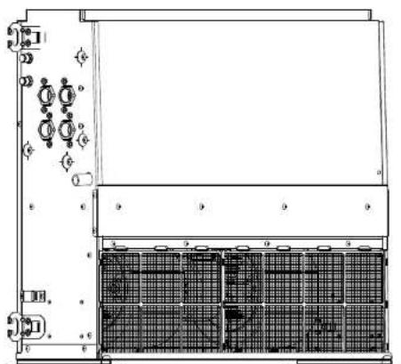
natural_image
Technical line drawing of a mechanical or electrical enclosure with grid panels and control panel (no text or symbols)text_image
Technical diagram of an electronic device with labeled components a through f, showing internal wiring and mounting points.natural_image
Technical line drawing of a rectangular electronic device with internal components and directional arrows indicating motion (no text or symbols)5 Монтаж
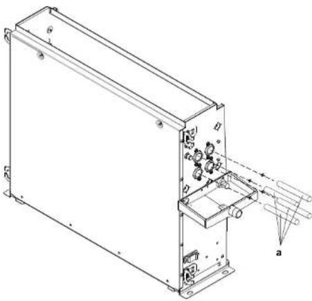
natural_image
Technical line drawing of a mechanical or electronic device with internal components and labeled parts (no readable text or symbols)text_image
Technical diagram of an electrical enclosure with labeled components including a base, cable, and wall-mounted unitnatural_image
Technical line drawing of a rectangular electronic device with internal components and mounting holes (no text or symbols)natural_image
Diagram of a cable or wire penetration device with exposed wires and connectors, showing no text or symbols.natural_image
Pure electrical circuit lines without any symbolstext_image
Technical diagram of an air conditioning unit with labeled components and directional arrows5 Монтаж
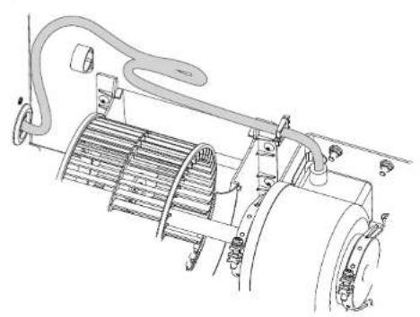
natural_image
Technical line drawing of a mechanical device with cooling fins and piping (no text or symbols)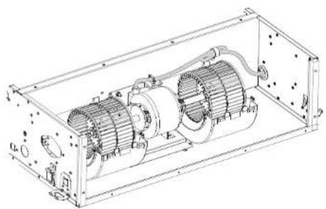
natural_image
Technical line drawing of an internal combustion engine housing (no text or labels)natural_image
Technical line drawing of an electrical enclosure with two motors and wiring (no text or symbols)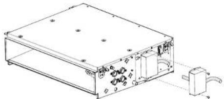
natural_image
Technical line drawing of a rectangular electronic device with mounting holes and a separate internal component (no text or symbols)natural_image
Technical line drawing of an internal combustion engine housing with visible components and wiring (no text or labels)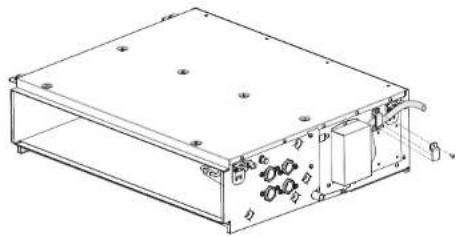
natural_image
Technical line drawing of a rectangular electronic device with internal components and mounting holes (no text or symbols)text_image
Technical diagram showing two electrical component layouts with labeled dimensions a and b, including internal components and a wire connection.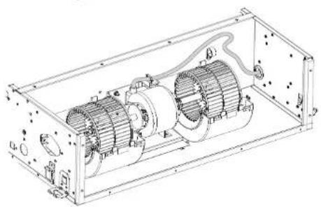
natural_image
Technical line drawing of an internal combustion engine housing with visible motors and wiring (no text or labels)6 Пусконаладка
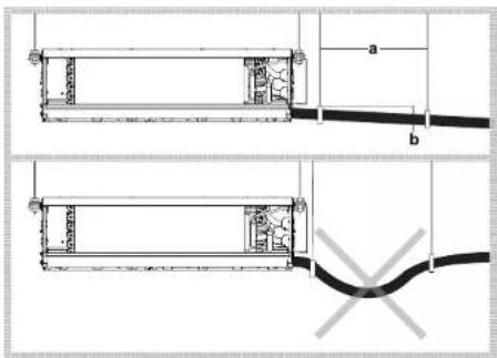
text_image
Technical diagram showing two cable installation steps with labeled components and a cross-sectional viewВертикальный монтаж
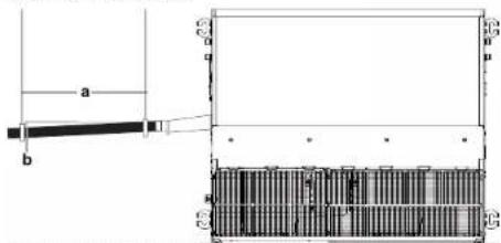
text_image
a b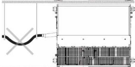
natural_image
Technical diagram of a mechanical or electrical component with no visible text, numbers, or symbols.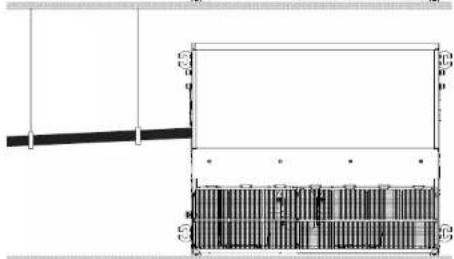
natural_image
Architectural cross-section diagram showing structural layers and doorways (no text or labels)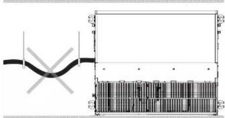
text_image
Technical diagram showing a pipe connection with cross-sectional view and labeled componentsnatural_image
Technical line drawing of a rectangular electronic device with labeled ports and connectors (no text or symbols present)text_image
Technical diagram of a chemical apparatus with labeled components and two views showing internal and external views.text_image
Exploded view diagram of a solar panel assembly with numbered components for identificationnatural_image
Technical line drawing of an electronic device casing with mounting holes and internal components (no text or symbols)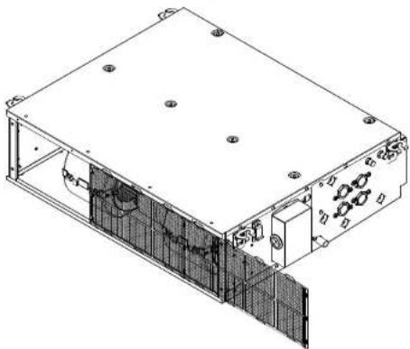
natural_image
Technical line drawing of an electronic device housing with internal components and mounting holes (no text or symbols)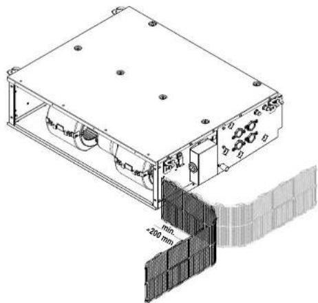
natural_image
Technical line drawing of a mechanical enclosure with internal components and a 200 mm dimension label (no readable text or symbols beyond measurement annotations)Вертикальный монтаж
natural_image
Technical line drawing of a mechanical or electrical enclosure with internal grid structure (no text or symbols)text_image
Technical diagram showing assembly of a mechanical component with labeled parts and a magnified detail view.natural_image
Two technical illustrations of a vacuum cleaner connected to a solar panel and a separate flat plate with a cable (no text or symbols)natural_image
Isometric technical drawing of a rectangular electronic device with mounting holes and internal components (no text or symbols)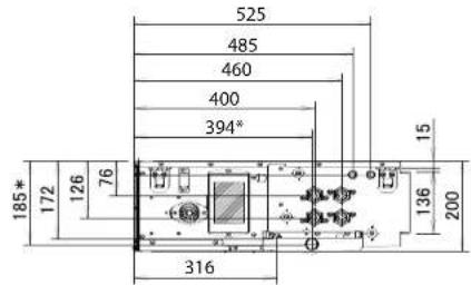
text_image
525 485 460 400 394* 185* 172 126 76 15 136 200 316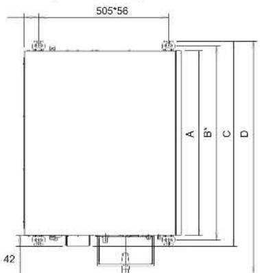
text_image
505*56 A B' C D 42| Единица измерения:MM | A B C D | ||
| FWE03~05 719 757 799 909 | |||
| FWE06 919 957 999 1109 | |||
| FWE07~11 1119 1157 1199 1309 |
natural_image
Technical line drawing of a server rack unit with indicator lights and grid panels (no text or symbols)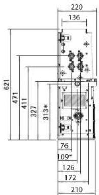
text_image
621 471 411 327 313* 220 136 76 09" 126 172 210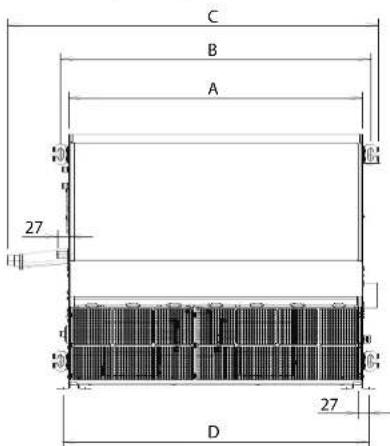
text_image
C B A 27 D 27| Единица измерения:MM | A B C D | ||
| FWE03~05 719 757 909 747 | |||
| FWE06 919 957 1109 947 | |||
| FWE07~11 1119 1157 1309 1147 |
natural_image
Technical line drawing of a rectangular electronic device with internal components and mounting holes (no text or symbols)natural_image
Technical line drawing of an electronic device casing with mounting holes and internal components (no text or symbols)natural_image
Technical line drawing of an electronic enclosure with mounting holes and internal components (no text or symbols)natural_image
Technical line drawing of an electronic device casing with internal components and a hand inserting a cable (no text or symbols)TEHLIKE: PATLAMA RISKI
natural_image
Technical line drawing of a mechanical assembly with hands holding parts (no text or symbols)natural_image
Isometric line drawing of a rectangular electronic device with a small internal component and labeled terminals (no text or symbols present)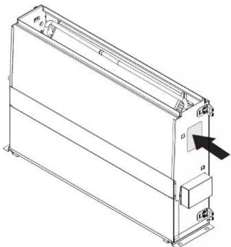
natural_image
Technical line drawing of a rectangular electronic device with mounting brackets and a black arrow pointing to a component (no text or symbols present)Model tanımlaması
Örnek: FWE03 DAFN5V3—L
text_image
Technical diagram showing a device layout with labeled components and directional arrows indicating movement or flow.Dikey montaj
text_image
Technical diagram showing mechanical assembly with labeled parts a, b, c, d and directional arrows indicating rotation or movement.text_image
Technical diagram of a server rack with labeled components and internal grid layoutnatural_image
Technical line drawing of a mechanical assembly with two views (a and b), showing internal components and structural details (no text or symbols present)text_image
Technical diagram of a mechanical assembly with labeled components and cross-sectional view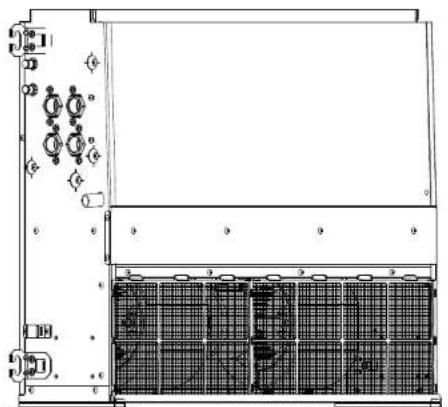
natural_image
Technical line drawing of a server rack with grid panels and indicator lights (no text or symbols)a Hava filtresi
b Servis kapağı
c Montai ayaklar
d Vidalar
e Hava filtresi
text_image
Technical diagram of an electronic device with labeled components and internal wiring connectionstext_image
Technical diagram of an electronic device with labeled components and directional arrows indicating light or measurement.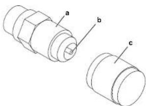
text_image
a b cnatural_image
Technical line drawing of an electronic device casing with internal components and mounting brackets (no text or symbols)a Bağlantı borusu
text_image
Technical diagram of an electrical switch assembly with labeled componentsa Terminal kapağı
natural_image
Technical line drawing of a rectangular electronic device with mounting holes and internal components (no text or symbols)natural_image
Diagram of a device emitting black wires into a container with a curved arrow indicating flow (no text or symbols)natural_image
Pure electrical circuit lines without any symbolsnatural_image
Technical line drawing of an electric motor assembly inside a housing (no text or labels)FWE03-11D
Fan coil üniteleri
3P443944-5E - 2019.09
DAIKIN
Montaj kilavuzu
5 Montaj
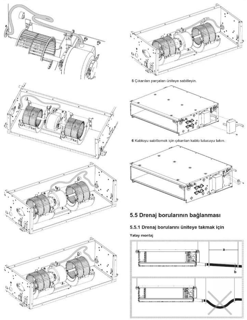
text_image
Technical diagram showing two cable installation steps with labeled components and a cross-sectional viewDikey montaj
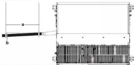
text_image
a b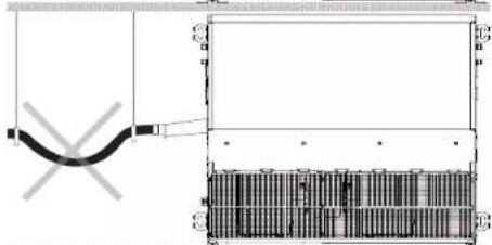
natural_image
Pure technical diagram showing a mechanical assembly with no text, numbers, or symbols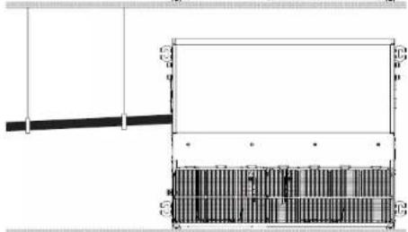
natural_image
Architectural cross-section diagram showing structural layers and dimensions (no text or labels)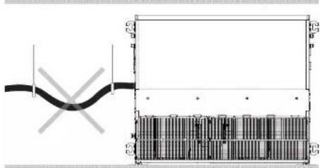
text_image
Technical diagram showing a pipe connection with cross-sectional view and internal structure labeled with letters A, B, C, D, E.natural_image
Technical line drawing of an electronic device chassis with labeled components (a and b), no readable text or symbols present.a Plastik su kovma sisesi
b Drenaj soketi
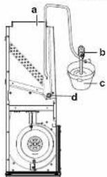
text_image
a b c dnatural_image
Pure schematic diagram of a laboratory apparatus with no text, numbers, or symbolstext_image
Exploded view diagram of an electronic device with numbered components for identificationnatural_image
Isometric technical drawing of a rectangular electronic device with internal components and mounting holes (no text or symbols)7 Bakım ve servis
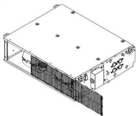
natural_image
Technical line drawing of an electronic device casing with internal components and mounting holes (no text or symbols)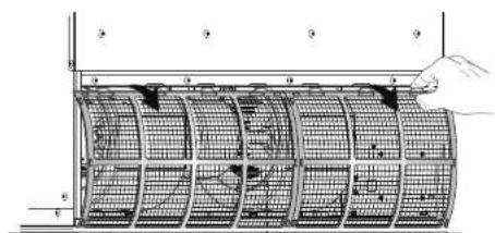
text_image
Technical diagram showing a grid-patterned structure with labeled components and a hand pointing to a component.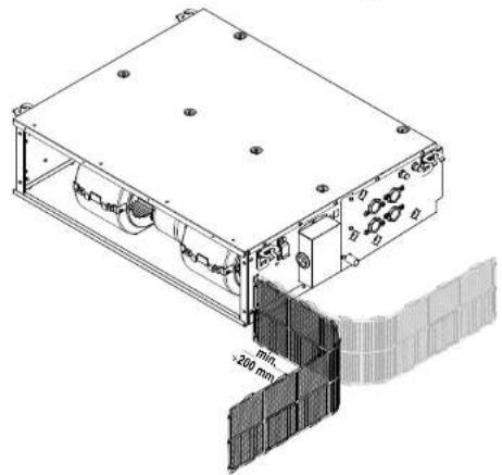
natural_image
Technical line drawing of a mechanical device with mounting holes and internal components, showing a 200 mm scale detail (no text or symbols beyond measurement annotations)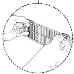
natural_image
Illustration of hands holding a grid-like object within a dashed circular border (no text or symbols)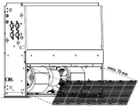
text_image
5min. 70 mmnatural_image
Technical line drawing of a server rack unit with internal grid and mounting holes (no text or symbols)natural_image
Technical line drawing showing a vacuum tube connected to a grid base and a separate flat plate with wires (no text or symbols)natural_image
Technical line drawing of an electronic device casing with internal components and mounting holes (no text or symbols)Dikey görünüm
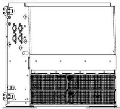
natural_image
Technical line drawing of a mechanical or electrical enclosure with internal components and mounting holes (no text or symbols)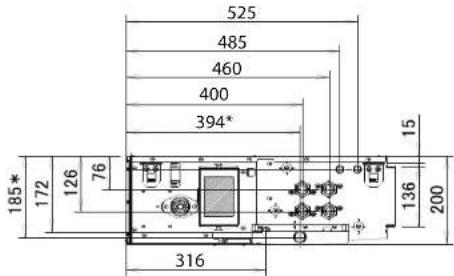
text_image
525 485 460 400 394* 185* 172 126 76 316 136 200 15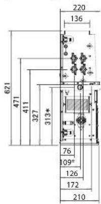
text_image
621 471 411 327 313* 220 136 76 09" 126 172 210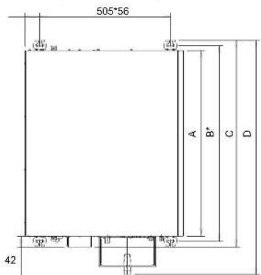
natural_image
Technical line drawing of a rectangular electronic device with internal components and mounting holes (no text or symbols)a Drenaj soketi kauçuğu
b Ek drenaj soketi
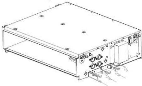
natural_image
Technical line drawing of an electronic device casing with internal components and mounting holes (no text or symbols)natural_image
Technical line drawing of an electronic device housing with mounting holes and internal components (no text or symbols)a Drenaj soketi kauçuğu
b Ek drenaj soketi

natural_image
Technical line drawing of an electronic device casing with internal components and a hand inserting a cable (no text or symbols)8 Teknik veriler
8.2 Kablo şeması
Terminalde
natural_image
Technical line drawing of a mechanical assembly with hands operating it (no text or symbols present)natural_image
Technical line drawing of a rectangular electronic device with internal components and mounting points (no text or symbols)text_image
Technical diagram of an electronic device with labeled components and dimensions, including connectors, switches, and a door.text_image
Technical diagram showing mechanical assembly steps with labeled parts a, b, c, dnatural_image
Technical line drawing of a mechanical assembly with labeled components (a and b), showing internal components and mounting features without any readable text or symbols.text_image
Technical diagram of a mechanical assembly with labeled components and cross-sectional view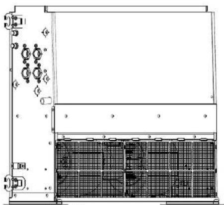
natural_image
Technical line drawing of a server rack with grid and indicator lights (no text or symbols)text_image
Technical diagram of an electronic device with labeled components and internal wiring connectionstext_image
Technical diagram of an electronic device with labeled components and directional arrows indicating flow or movement
natural_image
Technical line drawing of an electronic device casing with internal components and mounting holes (no text or symbols)a Összekötő cső
natural_image
Technical line drawing of an internal mechanical assembly with two cylindrical components (no text or symbols)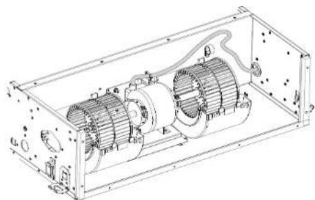
natural_image
Technical line drawing of an internal combustion engine assembly (no text or labels)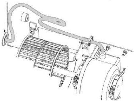
natural_image
Technical line drawing of a mechanical assembly with hoses and components (no text or symbols)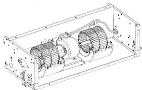
natural_image
Technical line drawing of an internal combustion engine housing with visible components and mounting holes (no text or labels)
natural_image
Technical line drawing of an electrical enclosure with two motors and wiring (no text or symbols)natural_image
Technical line drawing of a rectangular electronic device with internal components and a separate terminal block (no text or symbols)natural_image
Technical line drawing of an electric motor assembly enclosed in a rectangular frame (no text or labels)
natural_image
Technical line drawing of a rectangular electronic device with internal components and mounting holes (no text or symbols)5 Felszerelés
text_image
Technical diagram showing two views of a cylindrical device with labeled dimensions (a and b) and internal components, plus a close-up of the cable.natural_image
Pure electrical circuit lines without any symbols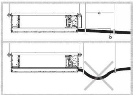
text_image
Technical diagram showing two mechanical components with labeled dimensions a and b, including internal structure and a cross symbol indicating a fault or failure.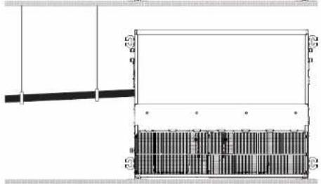
natural_image
Pure architectural or mechanical diagram showing a beam and column structure without any text, numbers, or symbols.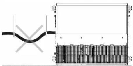
natural_image
Pure technical diagram showing a pipe connection and a grid layout with no text or symbolsnatural_image
Technical line drawing of an electronic device chassis with labeled components (a and b), no readable text or symbols present.text_image
Technical diagram of a laboratory apparatus with labeled components and a water tank in the backgroundnatural_image
Simple line drawing of a laboratory apparatus with a beaker, tubing, and a test tube (no text or symbols)text_image
Exploded view diagram of a solar panel assembly with numbered components for identificationnatural_image
Technical line drawing of a rectangular electronic device with internal components and mounting holes (no text or symbols)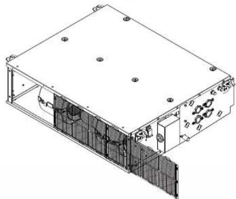
natural_image
Technical line drawing of an electronic device housing with internal components and mounting holes (no text or symbols)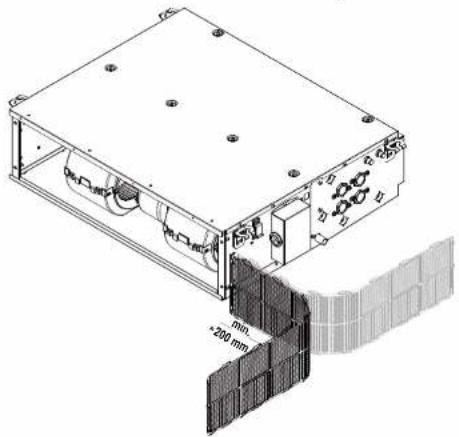
natural_image
Technical line drawing of a mechanical device with mounting holes and a 200 mm dimension annotation (no readable text or symbols)natural_image
Technical line drawing of a mechanical or electrical enclosure with internal grid structure (no text or symbols)natural_image
Technical line drawing of a simple electrical component with a motor and cable, next to a flat panel (no text or symbols)text_image
Technical diagram showing a grid-based device with labeled components and a magnified view of its internal structure.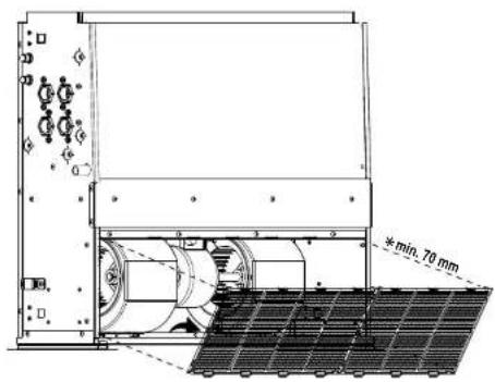
text_image
min. 70 mm8 Müszaki adatok
8 Müszaki adatok
natural_image
Technical line drawing of an electronic device casing with mounting holes and internal components (no text or symbols)natural_image
Technical line drawing of a server rack unit with indicator lights and grid panels (no text or symbols)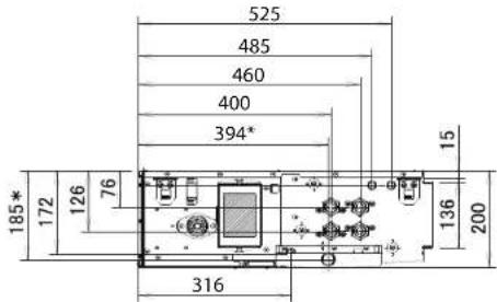
text_image
525 485 460 400 394* 185* 172 126 76 316 136 200 15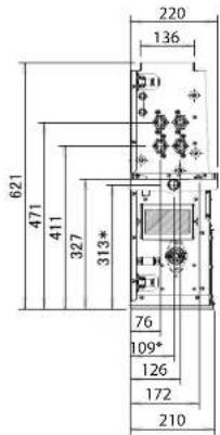
text_image
621 471 411 327 313* 220 136 76 109* 126 172 210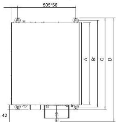
text_image
Technical diagram of an electronic device with labeled components and mounting pointsnatural_image
Technical line drawing of a rectangular electronic device with mounting holes and internal components (no text or symbols)natural_image
Technical line drawing of an electronic device housing with mounting holes and internal components (no text or symbols)natural_image
Technical line drawing of an electronic device casing with internal components and a hand inserting a cable (no text or symbols)8 Müszaki adatok
8.2 Huzalozási rajz
Kivezetés
Copyright 2019 Daikin
DAIKIN EUROPE N.V.