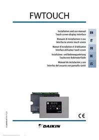
FWE03DAFN5V3-S - Air Conditioning DAIKIN - Free user manual and instructions
Find the device manual for free FWE03DAFN5V3-S DAIKIN in PDF.


User questions about FWE03DAFN5V3-S DAIKIN
0 question about this device. Answer the ones you know or ask your own.
Ask a new question about this device
Download the instructions for your Air Conditioning in PDF format for free! Find your manual FWE03DAFN5V3-S - DAIKIN and take your electronic device back in hand. On this page are published all the documents necessary for the use of your device. FWE03DAFN5V3-S by DAIKIN.
USER MANUAL FWE03DAFN5V3-S DAIKIN
4.1.2 Changing the air temperature set-point ..... p. 5
4.1.3 Changing the fan speed.... p. 5
4.2 USER MENU p.6
4.2.1 Time slots menu p. 6
4.2.2 Programming of time slots ..... p. 6
4.3 MAINTENANCE MENU p.7
4.3.1 Information menu ...... p. 7
5 PARAMETER LISTS ...... p. 8
5.1 CONFIGURATION PARAMETERS LIST.....p.8
5.1.1 Scroll and modify mode....p. 8
5.1.2 Table of parameters p. 8
5.1.3 Configuration constraints.... p. 8
5.1.4 Configurable digital output.... p. 9
5.1.5 Stand-by mode....p. 9
5.1.6 Interruption in the serial connection ..... p. 9
5.2 REGULATION PARAMETERS LIST....p.9
5.3 NETWORK AND CONNECTIONS PARAMETERS LIST (PASSWORD 20)..... p. 10
6 REGULATION LOGIC ...... p. 11
6.1 SUMMER/WINTER SWITCHOVER.... p. 11
6.2 VENTILATION p.11
6.2.1 General issues ...... p. 11
6.2.2 Natural convection.... p. 11
6.2.3 Step ventilation p. 11
6.2.4 Modulating ventilation p. 12
6.2.5 Forced speed p. 13
6.2.6 Fan enabling signal from water probe..... p. 13
6.3 VALVE.... p. 14
6.3.1 ON/OFF valve.... p. 14
6.3.2 Modulating valve p. 14
6.3.3 Valve enabling signal from water probe ..... p. 14
6.4 ELECTRICAL HEATING ELEMENTS...... p. 14
6.4.1 Start up p. 14
6.4.2 Heating element enabling signal from water probe p. 15
6.5 ECONOMY p.15
6.6 MINIMUM TEMPERATURE CONTROL..... p. 15
6.6.1 Start up ...... p. 15
6.7 DEHUMIDIFICATION p.15
6.7.1 Logic p. 15
6.7.2 Dehumidification enabling signal from water probe p. 16
6.8 ALARMS p.16
7 NETWORKS AND CONNECTIVITY ..... p. 17
7.1 CONNECTION TO MONITORING SYSTEM.... p. 17
7.2 "SMALL" NETWORK SOLUTIONS.... p. 19
7.3 MIXED NETWORK p.20
8 MEANING OF LED ...... p. 21
9 TECHNICAL SPECIFICATIONS ..... p. 22
10 INSTALLATION AND MAINTENANCE... p. 22
10.1 INSTALLATION OF THE PROBES.... p. 22
10.2 INSTALLATION OF THE REMOTE AIR PROBE ...... p. 23
10.3 INSTALLATION OF THE WATER PROBE ..... p. 23
10.4 INSTALLATION OF THE USER INTERFACE.... p. 24
10.5 ON-BOARD INSTALLATION OF THE CIRCUIT BOARD p. 24
10.6 ELECTRICAL CONNECTIONS p. 24
10.7 MAINTENANCE.... p. 25 Cleaning.... p. 25
10.8 TROUBLESHOOTING.... p. 25
10.9 I/O TABLE OF THE BOARD.... p. 26
10.10 CONFIGURATION EXAMPLES ...... p. 27
1 GENERAL CAUTIONARY NOTES
Carefully read this manual.
Installation and maintenance should be carried out by technical personnel qualified for this type of machine, in compliance with current safety regulations.
When receiving the unit please check its state verifying if any damage occurred during the transport. For installation and use of possible accessories please refer to the pertinent technical sheets.
The manual are subject to changes, in any times, without prior notice aimed at improving the product.
Daikin will not accept any liability for damage or injury caused as a result of installation by non-qualified personnel; improper use or use in conditions not allowed by the manufacturer; failure to perform the maintenance prescribed in this manual; use of spare parts other than original factory parts.
SAFETY SYMBOLS

Carefully read this manual.

Warning

Use personal protective equipment
⚠ WARNING: Electrical and electronic products may not be mixed with unsorted household waste. Do NOT try to dismantle the system yourself: the dismantling of the system, treatment of the refrigerant, of oil and of other parts must be done by an authorized installer
USE SUITABLE PPE (GLOVES FOR REFRIGERANT, PROTECTIVE GOGGLES)
and must comply with applicable legislation. Units must be treated at a specialized treatment facility for reuse, recycling and recovery. By ensuring this product is disposed of correctly, you will help to prevent potential negative consequences for the environment and human health. For more information, contact your installer or local authority.
2 GENERAL CHARACTERISTICS
The FWTOUCH controller has been designed to govern the operation of all the Daikin indoor hydronic units with a single-phase multi-speed motor or coupled to an inverter for fan speed modulation.
FWTOUCH controller is a system composed of:
— Circuit board comprising the power circuit, the microprocessor system and the removable screw connectors for the connection of the inlet and outlet devices;
— Touch screen display interface equipped with a clock and probes to read the ambient temperature and the ambient air humidity.
IMPORTANT: The connection between the
circuit board and the user interface is made by means of the appropriate connectors using a data transmission cable containing a pair of twisted and shielded conductors.
The controller makes possible serial communication for connecting to two types of networks:
— Solution with supervisor: connection to an external monitoring system with MODBUS RTU protocol on RS485 serial port;
— SMALL solution: connecting multiple FW-TOUCH controls in two possible configurations:
-
MASTER/SLAVE on RS485 serial port
-
MASTER/SLAVE on PLC (Power-Line
Communication).
— MIXED NETWORK solution: connection several FWTOUCH controls at various levels of autonomy:
- RS485 network MASTER (Supervisor or FW-TOUCH), sending instructions to RS485
SLAVES (known as zone MASTER);
of2. Zone MASTER (FWTOUCH), receiving instructions from RS485 network MASTER, sending instructions to the PLC SLAVES;
- PLC network SLAVE, operation identical to that of the zone master.
3 MAIN FUNCTIONS
— Automatic or manual (keyboard selectable) regulation of fan speed;
— Control of ON-OFF or modulating valves for two- or four-pipe systems;
— Control of a heating element for auxiliary heating;
— SUMMER/WINTER switchover (= cooling / heating) according to four possible modes:
- manual via keyboard;
- remote manual (from digital input);
- automatic, depending on water temperature;
- automatic, depending on air temperature.
— Control of the dehumidify function;
— Operation with TIME SCHEDULES
Additional features include:
— Digital input for external activation (for example: window contact, remote ON/OFF, occupancy sensor, etc.) that may enable or disable operation of the hydronic indoor unit (contact logic: see circuit board configuration parameters);
— Digital input for centralised remote cooling/heating switching (contact logic: see circuit board configuration parameters);
— Digital input for remote enabling of the ECONOMY mode (contact logic: see circuit board configuration parameters).
— One completely configurable digital output (no-voltage contact)
— Standard ambient air temperature probe (located inside the user interface);
— Water temperature probe (accessory), one or two (optional in case of 4-pipe system);
— Remote ambient air temperature probe (accessory) which, if connected, can be used in place of the one installed as standard in the user interface;
— Remote ambient air relative humidity probe (accessory).
4 SCREENS AND FUNCTIONS
4.1 USER INTERFACE
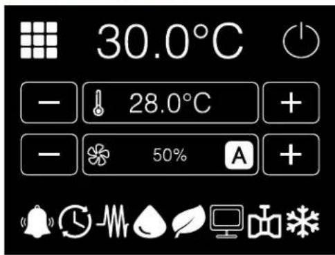
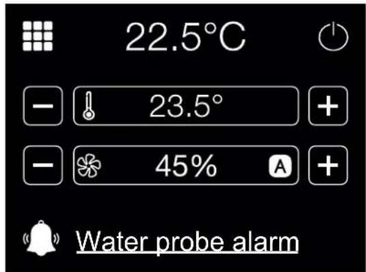
The main screen is composed of the following areas:
— user menu access key;
— room temperature (read by the remote probe
on the user interface or by the probe connected to the circuit board terminal board as configured);
— ON/OFF key;
— current temperature SET-POINT value, mod ifiable;
— fan status, modifiable;
— Status symbols



Active time schedules
Active minimum ambient temperature function
Electric heating element enabled
Open valve
Active economy function
Supervision connection
Presence of alarm (no other line symbol is displayed; text describing the alarm type appears)
Smartphone connection
Local Network connection

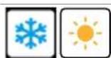
Summer mode (cooling)
Winter mode (heating)
4.1.1 User menu access
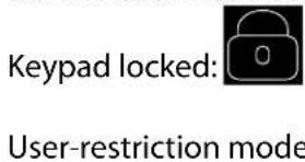
Access to the user menu is only allowed if the keypad has not been locked or the user-restriction function has not been activated.
text_image
Keypad locked: User-restriction mode
4.1.2 Changing the air temperature set-point
To change the air temperature SET-POINT, you must display the HOME screen with the hydronic indoor unit on, then proceed as follows:
— Press + / - keys located on the sides of the SET-POINT display area to change its value.
4.1.3 Changing the fan speed
To change the fan speed, you must display the HOME screen with the hydronic indoor unit on, then proceed as follows:
— Press + / - keys located on the sides of the fan display area to change its value.
— In the case of a modulating fan, the fan speed expressed as a percentage will be displayed in the place of the steps. Pressing the + / - keys allows you to vary this value from the minimum limit set to the maximum limit (see REGULATION MENU); setting values beyond the limits will cause the automatic ventilation mode to be automatically set;
— if the difference between the measured ambient air temperature and the set-point is within 0.5^ C, the fan switches off, and the message STDBY is displayed;
4.2 USER MENU
text_image
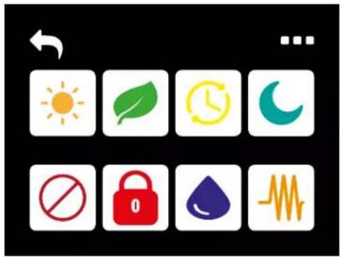
Weather and health icons including sun, leaf, clock, crescent, no prohibition sign, lock, water droplet, and heartbeat waveform| Maintenance menu access key. | ||
 | Keys for changing Summer/Winter mode. | |
 | Key for activating/deactivating Economy mode. | |
 | Key for setting and activating/deactivating the time slots. | |
 | Key for accessing the screen for setting and activating/deactivating the ambient antifreeze function. | |
 | Key for enabling/disabling user restrictions mode (password = 66). | |
 | Key for enabling/disabling the keypad lock (password = 99). | |
 | Key for accessing the screen for setting and activating/deactivating dehumidification. | |
 | Key for enabling/disabling the operation of the heating elements. This key is displayed ONLY if heating elements are present. | |
4.2.1 Time slots menu
text_image
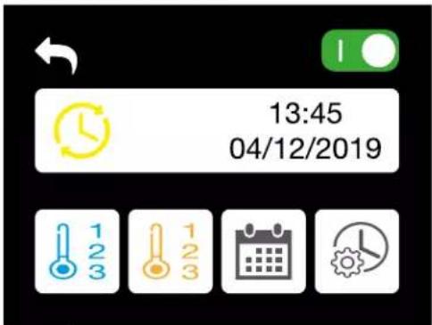
13:45 04/12/2019| Selector switch for activation/deactivation of operation with time slots | |
| Key for accessing the screen for setting the 3 summer temperatures | |
| Key for accessing the screen for setting the 3 winter temperatures | |
| Key for accessing the hourly and daily configuration screens | |
| Key for accessing the screen for setting the time and date |
4.2.2 Programming of time slots
Pressing the key from the time slots menu will take you to the following screen:
— Press the SET keys to set one of the 3 temperature sets in summer mode and winter mode for every hour of every day of the week (from Monday to Sunday).
— Press the COPY keys to copy the summer and winter profile of one day of the week to one or more other days of the week.
text_image
Icon set with six labeled UI icons including gear, globe, refresh, question mark, and refresh symbol


Key for returning to the main screen
Key for accessing the configuration parameters list (password = 10) see section p. 8
Key for accessing the regulation parameters list (password = 77) see section p. 9
Key for accessing the network and connections parameters list (password = 20) see section p. 10
Output test screen access key (password = 30)
Information menu access key
Key for resetting default values (password = 15)
4.3.1 Information menu
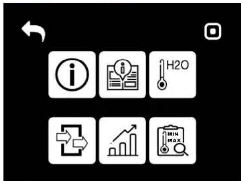
text_image
Mobile app icons with labels for information, data, H2O, progress chart, and MIN/MAX metrics


Key for returning to the main screen
Key for accessing the software version screen
Key for accessing pages of the manual
Key for accessing the water temperature screen
Key for accessing the inputs and outputs display screen
Key for accessing the display screen of graphs of the main values
Key for accessing the display screen of the minimums and maximums of the main values
5.1 CONFIGURATION PARAMETERS LIST

5.1.1 Scroll and modify mode
— to scroll the list, press the OK button at the top right;
— when changing the parameter, the NOT saved value appears orange;
— to save the settings, press the OK button at the top right and the text changes from orange to white.
5.1.2 Table of parameters
| ID Description Default Possible value | |||
| C1 Unit type 3 speed | 3 speed4 speed | ||
| C2 Pipes numbers 2 pipes | 2 pipes4 pipes | ||
| C3 Air probe Display | DisplayBoard | ||
| C4 | Temperature display | Celsius | CelsiusFahrenheit |
| C5 Ventilation type | Step | StepModulating | |
| C6 Valve type | Not included | Not includedOn/OffModulating | |
| C7 | Summer/Winter switching | From keypad/serial | From keypad/serialFrom digital inputAuto on water temperatureAuto on air temperature |
| C8 | Configuration output 07 | No use | (see dedicated paragraph) |
| C9 Output logic 07 | N.A | N.AN.C | |
| C10 | Heating elements | No | No/Yes |
| C11 | Water probe present | No | No/Yes |
| C12 | Number of 4-pipe unit water probes | 1 | 1/2 |
| C13 | Humidity probe | Display | Display/Board |
| C14 | ECONOMY from contact | No | No/Yes |
| C15 | ON/OFF from contact | No | No/Yes |
| C16 | Dehumidification from contact | No | No/Yes |
| ID Description Default Possible value | |||
| C17 | Fan mode in STANDBY | Standard | Always ON, Always OFF, Cyclical switching on |
| eC18T | Fan speed in STANDBY | Minimum | MinimumMediumMaximum |
| C19 | Natural convection | No | No/Yes |
| tC20 | Status with disconnected serial | Keypad / serial | Keypad / serialFrom supervisor |
| C21 | Language | Italian | Italian, English, French, German, Spanish |
| C22 | Display Stand-by | OFF | OFFClock, Temperature |
5.1.3 Configuration constraints
The configuration of the hydronic indoor unit must take the following requirements into account:
— if the heating element is present, the water probe must also be present;
— if the heating element and also the valve are present, the latter must be a 3-WAY valve (NOT A 2-WAY VALVE);
— If the SUMMER/WINTER switchover is set to "Auto on water temp.", the water probe must also be present;
— the heating element cannot be present in the 4-pipe units;
— in 4-pipe units with only one water probe, it is not possible to set summer/winter switcho-ver to "Auto on water temp.";
— summer/winter switchover can be set to "Auto on air temp." only if the heating element is present or if the hydronic indoor unit has a 4-pipe configuration;
— If the SUMMER/WINTER switchover is set to "Auto on water temp.", a 2-way valve cannot be used. The water probe must be installed at a point in the hydraulic circuit with low circulation.
5.1.4 Configurable digital output
The circuit board has a digital output (indicated with O7 in the wiring diagram) whose status can be linked to one of the operating states of the hydronic indoor unit given in the following list:
— Operating mode
— Cooling or heating request
— Cooling request
— Heating request
— Hydronic indoor unit ON/OFF status
— Alarm presence
— Dehumidification call
— Humidification call
— High room temperature
— Low room temperature
— Lack of heating water enabling signal
— Lack of cooling water enabling signal
— From the monitoring software and selectable by means of the configuration parameter "Configuration O7". Moreover it is possible to choose, with the setting of the next
parameter "Digital output logic", whether the relay status should follow the NO (Normally Open) or NC (Normally Closed) logic.
5.1.5 Stand-by mode
After 30 seconds during which no operation is performed on the user interface keypad, the main screen goes into standby mode, and displays the room temperature. Touch the screen at any point to return to the HOME screen.
5.1.6 Interruption in the serial connection
If the serial connection is interrupted with the controller set as SLAVE, FWTOUCH will maintain the ON/OFF and SUMMER/WINTER mode settings from the monitoring software or restore the last settings from the keypad depending on the selection of the corresponding configuration parameter.
5.2 REGULATION PARAMETERS LIST
| ID Description Default | ||
| R1 Minimum limit cooling SET 10.0°C | ||
| R2 Maximum limit cooling SET 35.0°C | ||
| R3 Minimum limit heating SET 5.0°C | ||
| R4 Maximum limit heating SET 30.0°C | ||
| R5 Minimum limit humidity SET 35% | ||
| R6 Maximum limit humidity SET | 75% | |
| R7 Hysteresis humidity | 5% | |
| R8 Offset on humidity reading | 0% | |
| R9 Modulating fan minimum value | 20% | |
| R10 | Modulating fan maximum value - Cooling | 100% |
| R11 | Modulating fan maximum value - Heating | 100% |
| R12 | Air probe offset | 0.0°C |
| R13 | Water probe offset | 0.0°C |
| R14 | Water probe offset, heating | 0.0°C |
| R15 | Air stratification offset | 0.0°C |
| R16 | Hysteresis Economy | 0.0°C |
| R17 | Cooling water enabling signal SET-POINT | 17.0°C |
| R18 | Cooling water enabling signal hysteresis | 5.0°C |
| R19 | Heating water enabling signal SET-POINT | 37.0°C |
| R20 | Heating water enabling signal hysteresis | 7.0°C |
| R21 | Dehumidification water enabling signal SET-POINT | 10.0°C |
| R22 | Dehumidification water enabling signal hysteresis | 2.0°C |
| ID Description Default | ||
| R23 | Valve water enabling signal SET-POINT | 30°C |
| R24 | Valve water enabling signal hysteresis 5.0°C | |
| R25 | Heating element water enabling signal SET-POINT | 39.0°C |
| R26 | Heating element water enabling signal hysteresis | 2.0°C |
| R27 | Minimum temperature control SET-POINT | 9.0°C |
| R28 | Minimum temperature control hysteresis | 1.0°C |
| R29 | Neutral zone | 5.0°C |
| R30 | % modulating fan in standby | 20% |
| R31 | Type of control | Proportional |
5.3 NETWORK AND CONNECTIONS PARAMETERS LIST (PASSWORD 20)
| ID Description Default Possible value | |||
| SETUP RS485 | |||
| N1 MST/SLV none | NoneMasterLocal slaveSlave to SPV | ||
| N2 Protocol Modbus Modbus | |||
| N3 Serial address 0 | 0-255(MASTER = 0; SLAVE = 1-255) | ||
| N4 Speed 9600 | 12002400480096001920038400 | ||
| N5 Temperature control from Master Yes | NoYes | ||
| SETUP OC | |||
| N7 MST/SLV Master | MasterSlave | ||
| N8 Serial address 0 | FWTOUCH master:0 | ||
| FWTOUCH Slave: 2-255 | |||
| Wireless network SETUP | |||
| N9 Wi-Fi/BLE enabling (Bluetooth) No | NoYes | ||
6 REGULATION LOGIC
6.1 SUMMER/WINTER SWITCHOVER
Four different and alternative logics are present to select the thermostat operating modes according to the configuration set on the controller:
— Local: chosen by the user with the MODE key
— Distance: depending on the DI1 Digital Input status
— depending on water temperature
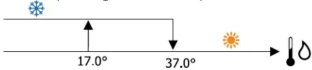
text_image
17.0° 37.0°INFO: In the case of water probe alarm, the
mode controller returns to the Local mode temporarily.
— depending on air temperature
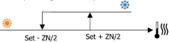
flowchart
graph LR
    A["Start"] --> B["Set - ZN/2"]
    B --> C["Feedback Loop"]
    C --> D["Set + ZN/2"]
    D --> E["Output Temperature"]
Where:
— Set is the air temperature set using the arrows
— ZN is the neutral zone
The thermostat operating mode is indicated on the display by the COOLING and HEATING symbols
6.2 VENTILATION
6.2.1 General issues
The controller can perform two types of fan control:
— step fan control, with a fixed number of selectable speeds (3 or 4);
— modulating fan control, with speeds ranging from 0% to 100%
Which type of control will be used clearly depends on the type of fan (step or modulating) installed in the unit. Step control in turn follows two different logics depending on the type of valve(s) (ON/OFF or modulating).
Summing up, the automatic control logics implemented by the controller (and described in detail below) are the following:
— 3-speed fan control with automatic step regulation and ON/OFF valve (or w/o valve), in cooling and heating modes;
— 4-speed fan control with automatic step regulation and ON/OFF valve (or w/o valve), in summer and winter modes;
— 3-speed fan control with automatic step regulation and modulating valve, in summer and winter modes;
— 4-speed fan control with automatic step regulation and modulating valve, in summer and winter modes;
— modulating fan control with ON/OFF valve, in summer and winter modes;
—modulating fan control with modulating valve.
6.2.2 Natural convection
By enabling the parameter from the configuration menu in units with valve, ventilation in heating mode is shifted by 0.5^ C to permit a natural convection phase.
6.2.3 Step ventilation
Using the UP/DOWN keys it is possible to select the following speeds:
— AUTOMATIC speed: depending on the set temperature and the room air temperature;
— EXTRA-LOW speed: can be selected only if the hydronic indoor unit has 4 speeds;
— MINIMUM speed
— MEDIUM speed
— MAXIMUM speed
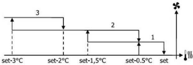
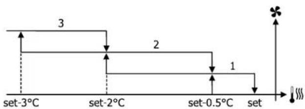
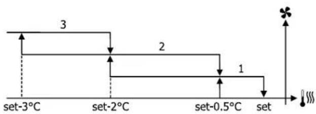
AUTOMATIC OPERATION FOR 3-SPEED HYDRONIC INDOOR UNITS AND ON/OFF VALVE(S) OR W/O VALVE(S):
- MINIMUM speed
- MEDIUM speed
- MAXIMUM speed
Cooling:
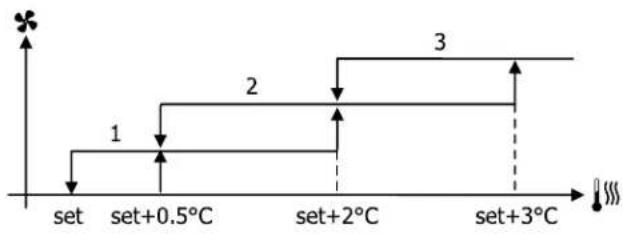
flowchart
graph TD
    A["set"] --> B["set+0.5°C"]
    B --> C["set+2°C"]
    C --> D["set+3°C"]
    D --> E["End"]
Heating:
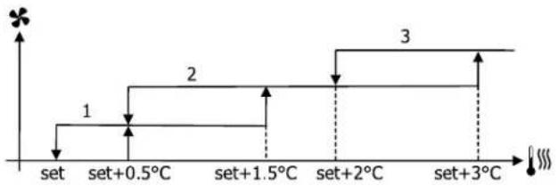
flowchart
graph TD
    A["set"] --> B["set+0.5℃"]
    B --> C["set+1.5℃"]
    C --> D["set+2℃"]
    D --> E["set+3℃"]
    C --> F["Step 1"]
    C --> G["Step 2"]
    D --> H["Step 3"]
Heating:
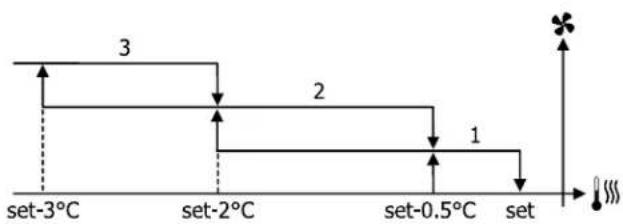
flowchart
graph TD
    A["set-3°C"] --> B["set-2°C"]
    B --> C["set-0.5°C"]
    C --> D["set"]
    style A fill:#f9f,stroke:#333
    style B fill:#f9f,stroke:#333
    style C fill:#f9f,stroke:#333
    style D fill:#f9f,stroke:#333
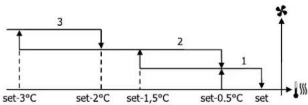
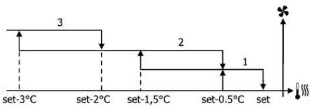
AUTOMATIC OPERATION FOR 4-SPEED HYDRONIC INDOOR UNIT AND ON/OFF VALVE(S) OR W/O VALVE(S):
- MINIMUM speed
- MEDIUM speed
- MAXIMUM speed EXTRA-LOW speed
Cooling:
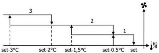
flowchart
graph TD
    A["set-3°C"] --> B["set-2°C"]
    B --> C["set-1,5°C"]
    C --> D["set-0.5°C"]
    D --> E["set"]
    style A fill:#f9f,stroke:#333
    style B fill:#f9f,stroke:#333
    style C fill:#f9f,stroke:#333
    style D fill:#f9f,stroke:#333
    style E fill:#f9f,stroke:#333
AUTOMATIC OPERATION FOR 4-SPEED HYDRONIC INDOOR UNIT AND MODULATING VALVE(S):
- MINIMUM speed
- MEDIUM speed
- MAXIMUM speed EXTRA-LOW speed
Cooling:
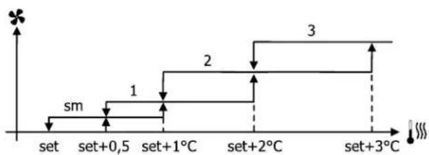
flowchart
graph TD
    A["set"] --> B["set+0,5"]
    B --> C["set+1°C"]
    C --> D["set+2°C"]
    D --> E["set+3°C"]
    style A fill:#f9f,stroke:#333
    style B fill:#ccf,stroke:#333
    style C fill:#cfc,stroke:#333
    style D fill:#fcc,stroke:#333
    style E fill:#cff,stroke:#333
Heating:
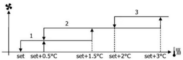
flowchart
graph TD
    A["set"] --> B["set+0.5°C"]
    B --> C["set+1.5°C"]
    C --> D["set+2°C"]
    D --> E["set+3°C"]
    style A fill:#f9f,stroke:#333
    style B fill:#ccf,stroke:#333
    style C fill:#cfc,stroke:#333
    style D fill:#fcc,stroke:#333
    style E fill:#cff,stroke:#333
Heating:
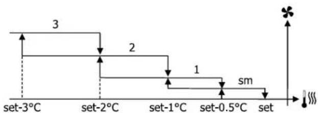
flowchart
graph TD
    A["set-3°C"] --> B["set-2°C"]
    B --> C["set-1°C"]
    C --> D["set-0.5°C"]
    D --> E["set"]
    style A fill:#f9f,stroke:#333
    style B fill:#f9f,stroke:#333
    style C fill:#f9f,stroke:#333
    style D fill:#f9f,stroke:#333
    style E fill:#f9f,stroke:#333
    note right of E "sm"
AUTOMATIC OPERATION FOR 3-SPEED HYDRONIC INDOOR UNIT AND MODULATING VALVE(S)
-
MINIMUM speed
-
MEDIUM speed
-
MAXIMUM speed
Cooling:
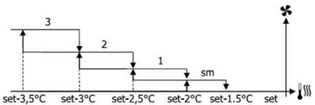
flowchart
graph TD
    A["set-3.5°C"] --> B["set-3°C"]
    B --> C["set-2.5°C"]
    C --> D["set-2°C"]
    D --> E["set-1.5°C"]
    E --> F["set"]
    style A fill:#f9f,stroke:#333
    style B fill:#f9f,stroke:#333
    style C fill:#f9f,stroke:#333
    style D fill:#f9f,stroke:#333
    style E fill:#f9f,stroke:#333
    style F fill:#f9f,stroke:#333
6.2.4 Modulating ventilation
As in the case of step control, the modulating fan control logic provides for two possible operating modes:
— AUTOMATIC operation
— FIXED SPEED operation
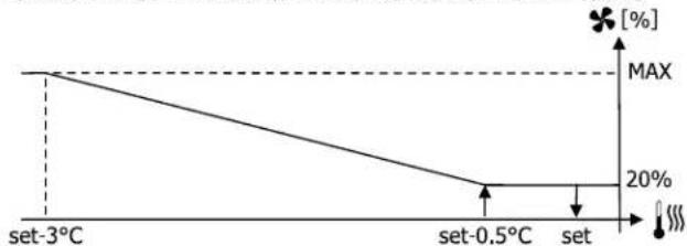
The operating percentage is selected using the + and - keys; however, setting a ventilation value
lower than the minimum (20%) or higher than the maximum (100%) will activate automatic ventilation.
TABLE WITH MANUAL, AUTO, AND FORCED AUTOMATIC OPERATION FOR 3- OR 4-SPEED HY-DRONIC INDOOR UNIT AND ON/OFF VALVE(S) OR W/O VALVE(S):
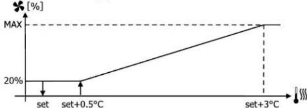
line
| Condition | Value [%] | |---|---| | set | 20 | | set+0.5°C | 20 | | set+3°C | MAX |HEATING WITH 3-SPEED CONFIGURATIONS
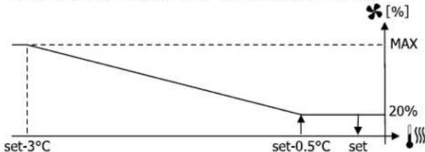
line
| Temperature | Value (%) | | :--- | :--- | | set-3°C | MAX | | set-0.5°C | 20 | | set | 20 |HEATING WITH 4-SPEED CONFIGURATIONS:
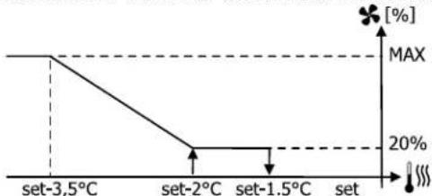
line
| Temperature | Value [%] | | :--- | :--- | | set-3.5°C | MAX | | set-2°C | 20% | | set-1.5°C | 20% | | set | 20% |6.2.5 Forced speed
The normal fan operating logic (both modulating and non-modulating) will be ignored in particular override situations that may be necessary to ensure correct control of the temperature or the unit operation.
This may occur:
— in the COOLING MODE:
— with on-board air probe and configurations with valve: the minimum speed available will be maintained even once the temperature has been reached
— with on-board air probe and valveless configurations: after every 10 minutes in which the fan remains idle a 2-minute cleaning is carried out at medium speed to enable the air probe to read the room temperature more correctly
— if ventilation in standby is always set to ON, the selected speed is maintained once the temperature setpoint has been reached.
— in the HEATING MODE:
— while the heating element is on: the fan is forced to run at medium speed
—once the heating element has turned off: a 2-minute post-ventilation cycle will be run at medium speed. (NB: this cycle will be completed even if the thermostat is switched off or in the event of a changeover to the cooling mode).
— if ventilation in standby is always set to ON, the selected speed is maintained once the temperature setpoint has been reached.
6.2.6 Fan enabling signal from water probe
Irrespective of the type of fan present (step or modulating), fan operation will be constrained by the system water temperature control. Based on the operating mode, different heating or cooling thresholds will be enabled.
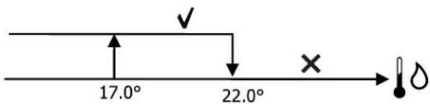
text_image
17.0° 22.0°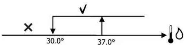
text_image
× 30.0° 37.0°Upon a call of the thermostat, the absence of the enabling signal will be indicated on the display by the flashing of the symbol representing the active Cooling or Heating mode. The enabling signal is ignored:
— if the water probe is not included or in alarm status because disconnected
— in the cooling mode with 4-pipe configurations
6.3 VALVE
The controller can manage 2- or 3-way valves of the ON/OFF type (i.e. completely open or completely closed) or modulating valves (the degree of valve opening may range between 0% and 100%).
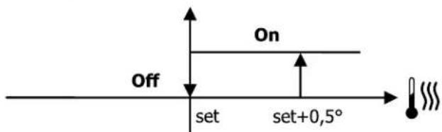
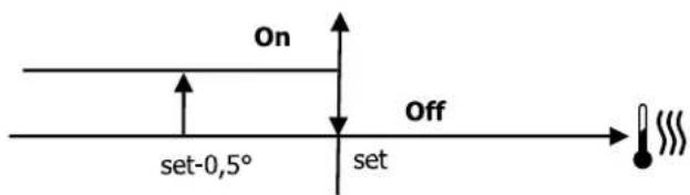
6.3.1 ON/OFF valve
The (2- or 3-way) valve opening is controlled according to the operating set-point and air temperature set-point
Cooling:
text_image
On Off set set+0,5°Heating:
text_image
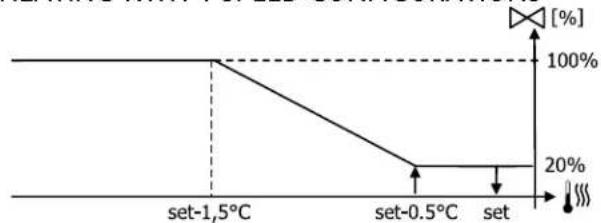
On set-0,5° Off set6.3.2 Modulating valve
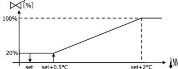
The (2- or 3-way) valve opening is controlled according to the operating set-point and air temperature set-point
The regulation logic for opening conforms to the diagrams below.
Cooling:
line
| Condition | Value [%] (%) | |---|---| | set | 20 | | set+0.5°C | 20 | | set+2°C | 100 |HEATING WITH 3-SPEED CONFIGURATIONS
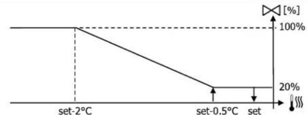
line
| Temperature | Percentage (%) | | :--- | :--- | | set-2°C | 100 | | set-0.5°C | 20 | | set | 100 |HEATING WITH 4-SPEED CONFIGURATIONS
line
| Temperature | Percentage (%) | | :--- | :--- | | set-1,5°C | 100 | | set-0.5°C | 20 | | set | 20 |6.3.3 Valve enabling signal from water probe
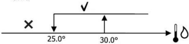
The checking of water temperature to enable valve opening is a function that concerns only configurations with 3-way valves and heating element. In such configurations the water temperature will be checked in the following cases:
— Heating with heating element: operating the heating element will force the fan to switch on; it is therefore necessary to prevent excessively cold water from passing through the unit.
text_image
× 25.0° 30.0°— Post-ventilation due to switching off of the heating element: maintained until the set time has elapsed, even if the operating mode is changed. During post-ventilation the water temperature enabling signal will coincide with the one seen for fan operation.
6.4 ELECTRICAL HEATING ELEMENTS
6.4.1 Start up
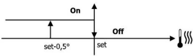
If the heating element's presence is set in advance from the configuration parameter and its use is enabled by means of a button in the USER MENU, it will be activated on a call from the thermostat according to the room temperature:
text_image
On Off set-0,5° setINFO: Switching it on will force the fan on as well.
6.4.2 Heating element enabling signal from water probe
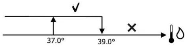
The enabling signal for the heating element is tied to the water temperature.
The related enabling logic is described below: HEATING
text_image
37.0° 39.0° ✓ ×The enabling signal will not be given if the water probe is either not present or disconnected.
6.5 ECONOMY
The Economy function aims to reduce the noise and power consumption of the hydronic indoor unit (e.g. during night operation). If the Economy function's presence is set in advance from the configuration parameter and its use is enabled by means of a button in the USER MENU, it will correct the set-point by 2.5°C and force the fan to run at the minimum available speed:
— Cooling: set-point + 2.5°C
— Heating: set-point - 2.5°C
6.6 MINIMUM TEMPERATURE CONTROL
If this logic's presence is set in advance from the configuration parameter and its use is enabled by means of a button in the USER MENU, it will prevent, while the thermostat is off, the room temperature from falling below a threshold that can be set on the same enabling screen, by forcing the unit into heating mode for the necessary amount of time.
If the heating element is present, it will be used only if it was previously selected as a resource in the heating mode.
6.6.1 Start up
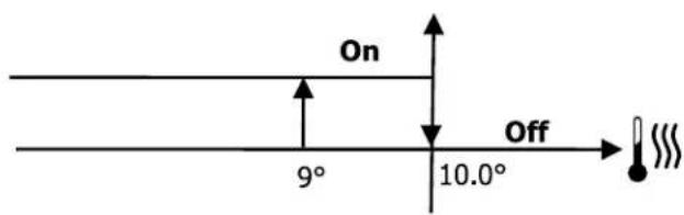
If this control is selected, the unit will switch on when the room temperature falls below 9^ C:
text_image
On 9° 10.0° OffWhen the temperature exceeds 10^ C the thermostat will resume its Off status.
INFO: Any OFF command from digital input will disable this logic.
6.7 DEHUMIDIFICATION
The FWTOUCH display shows an internal humidity probe; therefore, it is always possible to enable the dehumidification function.
If the dehumidification function, which can be used only in the cooling mode, is enabled on the dedicated screen that can be accessed from the USER MENU, it will operate the unit in order to reduce the humidity in the room until the set-point that can be set on the same enabling screen is reached.
6.7.1 Logic
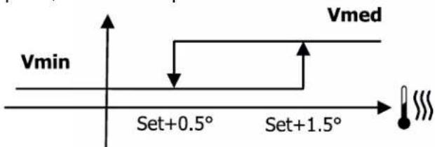
The fan will be forced to run at low speed or, if the air temperature is much higher than the set-point, at medium speed:
text_image
Vmin Set+0.5° Set+1.5° VmedIn order to bring the humidity to the set value,
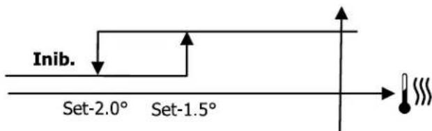
the fan (and valve, if present) will be activated even if the room temperature has already reached the programmed set-point (indicated on the display). Should the room temperature fall too far below this threshold, the logic will be temporarily inhibited.
text_image
Inib. Set-2.0° Set-1.5°6.7.2 Dehumidification enabling signal from water probe
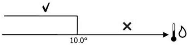
Enabling of the dehumidification function is tied to the water temperature. The related enabling logic is described below:
text_image
✓ 10.0° × →If enabling conditions do not exist, the dehumidification function will be temporarily inhibited. The same will occur in the event that the probe is disconnected.
INFO: Once the target level of humidity is reached or the controller is switched OFF, de-humidification will be disabled.
6.8 ALARMS
The alarms managed by the controller and indicated on the display are as follows:
— Air probe alarm
— Water probe alarm
— Humidity probe alarm
— Minor alarm from ID (caused by closing the ID4 input)
— Serious alarm from ID (caused by closing the ID5 input)
— PLC connection alarm (caused by loss of the connection of the display to the board)
text_image
22.5°C - 23.5° + - 45% A + Water probe alarm7 NETWORKS AND CONNECTIVITY
FWTOUCH offers the possibility to interface in networks of the type:
-
RS485 network with monitoring software. See figure 11.1 p. 144
-
SMALL network: SMALL RS485 network and SMALL power-line communication network
-
MIXED network (Supervisor+ PLC or RS485 + PLC) 11.4 p. 144
7.1 CONNECTION TO MONITORING SYSTEM
Through the RS485 serial port it is possible to connect the FWTOUCH controllers (up to 247 hydronic indoor units) to a management software programme that uses the MODBUS RTU standard as communication protocol with the following features:
— Settable baud rate (default: 9600);
— no parity
— 8 data bits
— 1 stop bit
Within a monitoring network, each FWTOUCH controller behaves like a SLAVE towards the centralised management system that constitutes the MASTER of the (see figure) 11.1 p. 144 network.
Once you have wired the network, you must configure each FWTOUCH controller. Enter the list of network and connection parameters (accessible via the key in the USER MENU) and set the RS485 SETUP parameters as follows:
— MST/SLV = "Slave from SPV"
— Protocol="Modbus"
» Coil status (digital read/write)
| Description | |
| 1 | ON/OFF controller |
| 2 | SUMMER/WINTER controller |
| 3 | ECONOMY controller |
| 4 | ANTIFREEZE ENABLING controller |
| 5 | HEATING ELEMENTS ENABLING controller |
| 6 | modulating fan MAN/AUTO controller |
| 7 | ON/OFF enabling from MASTER |
| 8 | ECONOMY enabling from MASTER |
| 9 | SUMMER/WINTER enabling from MASTER |
| 10 | ANTIFREEZE enabling from MASTER |
» Input status (digital read-only)
| Description | |
| 1 | Hydronic indoor unit ON/OFF |
| 2 | SUMMER/WINTER |
— Serial address = set a value from 1 to 255
— Speed = set according to the needs of the Master, leave the PLC SETUP parameters unchanged (MST/SLV = none).
INFO: for details on the network wiring it is recommended to read the document "RS485 network guidelines", available in the Daikin website's download area.
The functions recognized and managed by the controller as SLAVE are the following:
| Code Description | |
| 01 | coil status reading |
| 02 | input status reading |
| 03 | holding register reading |
| 04 | input register reading |
| 15 | coil status multiple writing |
| 16 | holding register multiple writing |
⚠ WARNING: As a result of the use of different MODBUS protocol standards, the addresses shown in the following tables may differ by one unit.
The following are the available variables:
| Description | |
| 11 | HEATING ELEMENTS enabling from MASTER |
| 12 | SET-POINTS enabling from MASTER |
| 13 | SET-POINT LIMITS enabling from MASTER |
| 14 | FAN SPEED enabling from MASTER |
| 15 | KEYPAD LOCK controller |
| 16 | HUMIDITY CONTROL enabling signal from MASTER |
| 17 | HUMIDITY CONTROL enabling |
| 18 | CONFIGURABLE DIGITAL OUTPUT NO7 controller |
| 19 | Enable control for TIME SLOTS |
| Description | |
| 3 | ECONOMY active |
| 4 | ANTIFREEZE active |
| 5 | presence of ALARM |
| 6 | Room temperature probe alarm |
| 7 | Water temperature probe alarm |
| 8 | Hot water temperature probe alarm(only if 4-pipe hydronic indoor unit) |
| 9 | Ambient humidity probe alarm |
| 10 | Number of speeds (3 or 4) |
| 111 | Number of pipes (2 or 4) |
| 12 | Fan type (STEP/MODULATING) |
| 13 | Regulation probe(USER INTERFACE/CIRCUIT BOARD) |
| 14 | Presence of heating elements |
| 15 | Presence of humidity probe |
| 16 | Digital output 1 (01) status |
| 17 | Digital output 2 (02) status |
| Description | |
| 18 | Digital output 3 (03) status |
| 19 | Digital output 4 (04) status |
| 20 | Digital output 5 (05) status |
| 21 | Digital output 6 (06) status |
| 22 | Digital output 7 (07) status |
| 23 | Presence of water probe |
| 24 | Presence of hot water probe (4-pipe hydronic indoor unit) |
| 25 | Dehumidification enabled |
| 26 | Open valve |
| 27 | Hydronic indoor unit switched off from remote contact |
| 28 | (MANUAL/AUTOMATIC) regulation of fan speed |
| 29 | Active heating element |
| 30 | Presence of valve |
| 31 | ECONOMY enabling from contact |
» Holding register (internal/analogue read/write)
| Description | |
| 1 | Summer temperature SET-POINT (cooling) |
| 2 | Summer temperature SET-POINT minimum limit |
| 3 | Summer temperature SET-POINT maximum limit |
| 4 | Winter temperature SET-POINT (heating) |
| 5 | Winter temperature SET-POINT minimum limit |
| 6 | Winter temperature SET-POINT maximum limit |
| 7 | Single temperature SET-POINT(if SUM/WIN on water/air temp.) |
| 8 | Humidity SET-POINT |
| Description | |
| 9 | Minimum limit humidity SET |
| 10 | Maximum limit humidity SET |
| 11 | Step fan speed:0 = extra-low speed1 = min. speed2 = med. speed3 = max. speed4 = AUTO sp. |
| 12 | Modulating fan speed |
» Input register (Internal/analogue read-only)
| Description | |
| 1 Room temperature | |
| 2 Ambient humidity | |
| 3 Water temperature | |
| 4 Hot water temperature (only if 4-pipe hydronic indoor unit) | |
| 5 | Step fan status:0 = fan stopped1 = extra-low sp.2 = min. speed3 = med. speed4 = max. speed |
| 6 % value of modulating fan | |
| 7 % value of analogue output 1 | |
| Description | |
| 8 % value of analogue output 2 | |
| 9 % value of analogue output 3 | |
| 10 Active temperature SET-POINT | |
| 11 Summer temperature SET-POINT | |
| 12 Winter temperature SET-POINT | |
| 13 | Single temperature SET-POINT (if SUM/WIN on water/air temp.) |
| 14 Active humidity SET-POINT | |
| 15 Valve Type (NO VALVE / ON-OFF / MODULATING) | |
7.2 "SMALL" NETWORK SOLUTIONS
The "SMALL" network solutions constitute a Master/Slave network system in which one of the controllers FWTOUCH carries out the function of MASTER while all the other network controllers FWTOUCH carry out the function of SLAVE. There are two possibilities of implementation, each with different functions and type of connection:
— SMALL network on RS485
— SMALL network on POWER-LINE COMMUNICATION
7.2.1 SMALL network on RS485
In this case the connection is made via an RS485 bus, consisting of a twisted and shielded 2-conductor data cable. See 11.2 p. 144
INFO: For details on the network wiring it is recommended to read the document "RS485 network guidelines", available in the Daikin website's download area.
The MASTER controller sends the following settings to the SLAVE controllers:
— Operating mode: (Cooling or heating);
— ON/OFF status of the controller: all SLAVE controllers will conform to the ON/OFF status of the MASTER controller;
— Enabling minimum room temperature control;
— Room temperature SET-POINT;
or (according to the "Temperature control from MASTER" parameter in the "Networks and Connections" menu):
— Limits for adjusting the room temperature SET-POINT (in both SUMMER and WINTER modes): on each SLAVE controller the SET-POINT can be adjusted by ±2^ C around the SET-POINT value programmed on the MASTER controller.
As regards the ON/OFF status, on each SLAVE controller the following is allowed:
— automatic local ON, in the event of a request from the minimum room temperature control function
— Automatic local ON/OFF according to the time slots, where enabled;
— OFF on SLAVE controller from digital input is enabled.
Each SLAVE controller retains autonomy with respect to fan speed, activation of the ECONOMY function and selection of the SETPOINT (within the above-described limits).
This type of network does not allow the presence also of a monitoring network because the RS485 serial ports of all controllers (both MASTER and SLAVE) are already occupied due to the implementation of the SMALL network.
Once you have wired the network, you must -configure each FWTOUCH controller. Enter the list of network and connection parameters (accessible via the key in the USER MENU) and set the RS485 SETUP parameters as follows:
— MST/SLV = set "Master" on the FWTOUCH controller that constitutes the MASTER of the network, and set "Local Slave" on all FW-TOUCH controllers that constitute the SLAVES of the network.
— Protocol="Modbus"
— Serial address = set a value from 1 to 255 only in the SLAVE controllers.
— Speed = do not change (9600)
Leave the PLC set-up parameters unchanged (MST/SLV = none).
7.2.2 SMALL network on power-line communication
This type of configuration makes it possible to control up to a maximum of 32 hydronic indoor units via a single user interface.
The connection is made via a PLC bus, consisting of a twisted and shielded 2-conductor data cable. See 11.3 p. 144.
The MASTER controller, in this case, imposes on all SLAVE controllers connected to the network an operation (instant by instant) that is identical to that of the MASTER controller itself. Therefore, each SLAVE controller has no decision-making autonomy and does not have its own user interface.
Before connecting the circuit boards to the network, it is necessary to configure each circuit board.
Connect the user interface to each circuit board. Enter the list of network and connection parameters (accessible via the key in the USER MENU) and set the PLC SETUP parameters as follows:
— MST/SLV = set "Master" on the circuit board
that constitutes the MASTER of the network, and set "Slave" on all the SLAVES of the network.
— Serial address = set a value from 2 to 34 on the SLAVE controllers.
At this point it is possible to connect all the circuit boards to the network.
WARNING: once the circuit board is set as SLAVE, it can no longer communicate with
any user interface after the controller is re-started. In this case you need to perform a RESET according to the following procedure: disconnect the circuit board from the network and, while keeping it powered, short-circuit digital input 10 for 15 seconds (terminals I10 and IC).
WARNING: all hydronic indoor units (i.e. both MASTER and SLAVES) connected to the network must have the same configuration.
7.3 MIXED NETWORK
The SMALL network on power-line communication can also be connected to a monitoring network (Supervisor solution or SMALL) on RS485 through the RS485 serial port of the MASTER controller, thus obtaining what is known as a
MIXED NETWORK. Figure 11.4 p. 144 shows a diagram of the mixed network consisting of SMALL network on POWER-LINE COMMUNICATION combined with a monitoring network.
» Summary table of parameters
| RS485 Supervisor BMS SMALL RS485 | SMALL OC | Mixed Network | ||
| MST/SLV Slave to SPV | FWTOUCH Master: Master | - | FWTOUCH Master: Master | |
| FWTOUCH Slave SLAVE to PSV | - | FWTOUCH Slave SLAVE to PSV | ||
| Protocol Modbus Modbus - Modbus | ||||
| Serial address 1...255 | FWTOUCH Master:0 | - | FWTOUCH Master:0 | |
| FWTOUCH Slave: 1...255 | - | FWTOUCH Slave: 1...255 | ||
| Speed | According to the Master | 9600 | - | 9600 |
| OC | |||
| MST/SLV | - | - | FWTOUCH Master: MasterMaster FWTOUCH: Slave |
| Serial Address | - | - | FWTOUCH Master: 0FWTOUCH Master: 2...255 |
8 MEANING OF LED
| Blue Green Red | |||
| LED status | Hydronic indoor unit off | Hydronic indoor unit on | Presence of alarm |
| Network LED PLC Master | Communication ok | Absence of communication |
INFO: Looking at the power board from the front, the NETWORK LED is on the left and the STATUS LED is on the right.
9 TECHNICAL SPECIFICATIONS
| Power supply | 230Vac 50/60Hz |
| Operating temperature | Electrical input 2.5 W |
| Storage temperature | Range 0-50☒ |
| No. IP protection rating | Range -10 to 60°C |
| Circuit board type | IP30 (user interface) |
| Output relays | Type 1.C |
| Inputs | NO 5A @ 240V (Resistive)Max ambient temperature 105°CMicro-interruption |
| Temperature probes | NTC temperature sensorsActive probes 0-5 VVoltage-free contacts (digital inputs) |
| Humidity probe | NTC sensors 10K Ohm @25°C Range -25 to 100☒ |
| Max. cable cross-section for terminals | 1,5 mm ^2 |
| Pollution rating | Class II |
| Heat/fire resistance category | Category D |
| Overvoltage category | Category II |
| EMC compliance standards | EN 61000-6-1(2007)EN 61000-6-3(2007) + A1(2011) |
| SAF Standards | EN 60730-2-9:2010EN 60730-1:2000 + A1:2004 + A2:2008 + A12:2003 + A13:2004 + A14:2005 + A16:2007 |
10 INSTALLATION AND MAINTENANCE
⚠ WARNING unit installation and start-up must be entrusted to competent personnel and performed in a workmanlike manner, in accordance with current regulations.
For each unit an (IL) switch should be mounted on the power supply, with opening contacts at a distance of at least 3 mm and a suitable protection fuse (F).
⚠ WARNING Install the unit, circuit breaker (IL) and/or any remote controls in a place out of reach of persons who may be taking a bath or shower.
WARNING the EMC filters connected to frequency converters (inverters) can create leakage currents toward ground (in order to make the unit EMC compliant, by reducing conducted emissions on power supply line). Depending on installation site, this can force
the cut out of the differential safety switch. It is recommended to install a separate differential safety switch, only for the BLDC unit, with an adjustable threshold for the cut out current.
IMPORTANT: Maintenance operations must be carried out only by a service centre authorised by the manufacturer or by qualified personnel. For safety reasons, before carrying out any maintenance or cleaning operations, turn off the unit by moving the electronic control to "OFF" and turning off the main switch (0 position).
The installation procedures for the user interface, the circuit board, and the probes are described below, with specific instructions for the individual hydronic indoor units of the Daikin range.
10.1 INSTALLATION OF THE PROBES
The FWTOUCH controller manages the following probes:
— Air temperature probe integrated in the user interface; no special installation operation is required.
— Probe (optional and alternative to the previous one) connected to the circuit board for reading the temperature of the air drawn in by the unit or at any other point in the environment subject to temperature regulation (REMOTE AIR PROBE).
— Probes (optional) for reading the water temperature: it is possible to connect one or two probes depending on whether the unit is connected to a 2- or 4-pipe system.
— Probe (optional) for reading the ambient relative humidity linked to the circuit board
⚠️ IMPORTANT To prevent disturbance and consequent malfunctions, make sure that the probe cables are NOT situated in proximity to power lines (230V).
10.2 INSTALLATION OF THE REMOTE AIR PROBE
The use of the remote air probe for regulating the room temperature is optional. When used, it becomes the main regulation probe in place of the probe located in the user interface. In any case it is always possible to choose the main room temperature regulation probe by means of the "air probe" parameter contained in the CONFIGURATION MENU.
The remote air probe must always be connected to terminals L1-IC of the circuit board.
FWV/L/M-D & FWZ/R/S-A
Use the plastic adhesive probe holder provided:
— Fan coil unit without support base (11.5 p. 145)
— Fan coil unit with support base (11.6 p. 145)
— Fan coil unit with front intake (11.7 p. 145)
10.3 INSTALLATION OF THE WATER PROBE
The water temperature probe (white cable) is an optional accessory.
In the case of 2-pipe hydronic indoor units (single coil), the water probe must be connected to terminals L2 - IC of the circuit board.
In the case of 4-pipe hydronic indoor units, it is possible to choose (using the "Number of water probes" parameter in the CONFIGURATION MENU) how many probes (one or two) to use.
If you choose to use a water probe, it must be installed in such a way as to read the temperature of the heating water (i.e. installed on the hot water coil) and connected to terminals L2 - IC of the circuit board.
If instead you choose to use two water probes, the probe for reading the cold water temperature must be connected to terminals L2 - IC of the circuit board, and the probe for reading the hot water temperature must be connected to terminals L3-IC of the circuit board.
FWV/L/M-D & FWZ/R/S-A
Use the special copper holder for the water probe and position it as described below, depending on the type of installation.
Fan coil units for:
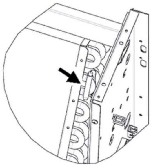
— 2-PIPE system - W/O VALVE or WITH 2-WAY VALVE: the water probe must be positioned on the heat exchanger (Fig.11.8);
— 4-PIPE system - W/O VALVE or WITH 2-WAY VALVES: the water probe (if one only) must be positioned on the heating circuit's heat exchanger (11.9 p. 146); the second probe, if any, must be positioned on the cooling circuit's heat exchanger;
— 2-PIPE system - WITH 3-WAY VALVE: the water probe must be positioned at the valve inlet, on the branch coming from the system
(11.10 p. 146);
— 4-PIPE system - WITH 3-WAY VALVES: the water probe (if one only) must be positioned at the heating valve inlet, on the branch coming from the circuit (11.11 p. 146); the second probe, if any, must be positioned at the cooling valve inlet on the branch coming from the circuit.
FWD-A/FWN-A
Example, valves mounted on the left side (11.12 p. 146):
— In the case of valveless FWD-A/FWN-A hydronic indoor units, for two-pipe systems, the water probe must be positioned on the pipe at the heat exchanger inlet.
— In the case of valveless FWD-A/FWN-A hydronic indoor units, for four-pipe systems, the water probe must be positioned on the pipe at the heating circuit heat exchanger inlet.
FWB-C/FWP-C
Example, valves mounted on the left side (11.13 p. 147):
— In the case of valveless FWB-C/FWP-C hydronic indoor units, for two-pipe systems, the water probe must be positioned on the pipe at the heat exchanger inlet.
— In the case of valveless FWB-C/FWP-C hydronic indoor units, for four-pipe systems, the water probe must be positioned on the pipe at the heating circuit heat exchanger inlet.
10.4 INSTALLATION OF THE USER INTERFACE
Choose an installation site where you will have easy access to the user interface for setting the functions and accurately read the room temperature (at least 1.5 m from floor level). You should avoid:
— positions directly exposed to sunlight
— positions exposed to direct currents of warm or cold air
— placing obstacles that impede an accurate temperature reading (drapes or furniture);
— constant presence of steam (kitchens, etc.)
— covering it or recess mounting it on the wa For wall mounting of the user interface it is advisable to use an electrical box to be installed in a 503 electrical enclosure, behind the controller, to accommodate the cables. Follow the instructions below for installation:
— Remove the locking screw of the user inter-It is recommended to use a data network cable face (11.14 p. 147). consisting of a pair of twisted and shielded con-
— If a 503 electrical enclosure is used, pass theductors. It is also recommended to connect the cables through the slot at the base of the user interface and use the holes provided for fastening (11.14 p. 147). shielding conductor to the (-) terminal both on the side of the user interface and on the circuit board (p. 149 and p. 150).
— Otherwise, drill holes in the wall where you plan to install the user interface, in positions corresponding to the fastening slots on the controller base. Use the user interface base as a drilling template. Pass the cables through the slot at the base and use expansion anchors to secure it to the previously drilled wall (11.15 p. 147).
— Connect the terminal to the user interface. — Close the controller using the locking screw.
The connection between the user interface and the circuit board must be performed using the 2-terminal connectors of the power-line communication found on both devices (see wiring diagram). In the case of connection between circuit boards, there are two connectors: it doesn't matter which connector you connect to.
10.5 ON-BOARD INSTALLATION OF THE CIRCUIT BOARD
On the hydronic indoor units FWV/L/M-D & FWZ/R/S-A and FWD-A/FWN-A, mount the circuit board on the fastening bracket using the 9.5 mm long screws provided (FWV/L/M-D & FWZ/R/S-A-D & FWZ/R/S-A 11.17 p. 148; FWD-A/FWN-A 11.19 p. 148);
— Screw the 3-way terminal block onto the bracket using the 25 mm long screws
provided;
— Mount the bracket on the side of the unit opposite the water inlet/outlet manifolds;
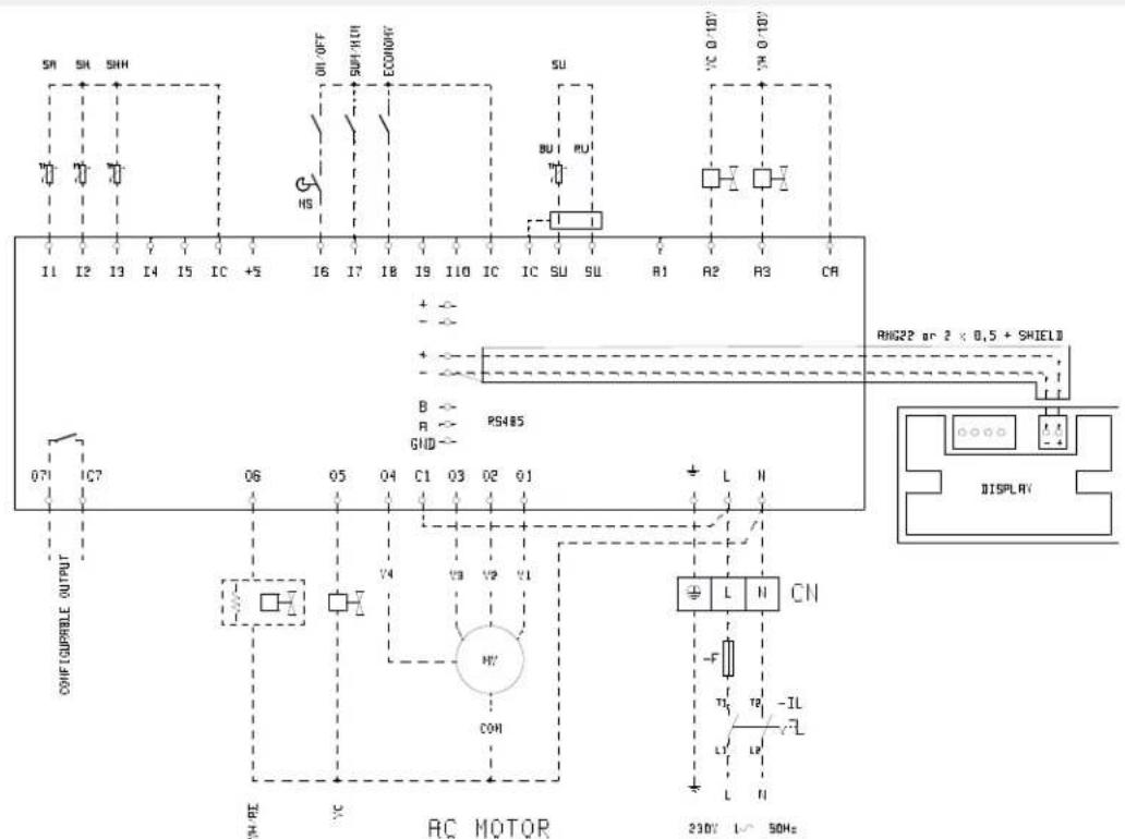
— Make the electrical connections according to the wiring diagram; for the connection between the terminal block of the hydronic indoor unit (CN) and the circuit board use a cable with a 1.5 mm ^2 cross-section.
10.6 ELECTRICAL CONNECTIONS
WARNING: All operations must be performed by qualified service personnel in accordance with current laws and regulations. For any electrical work on the unit, refer to the wiring diagrams provided with the hydronic indoor unit.
NOTE It is also suggested to verify that the characteristics of the mains power supply are adequate for the power consumption indicated in the table of electrical data.
IMPORTANT: Before carrying out any operation on electrical parts, make sure the power
supply is disconnected. Check that the mains supply voltage corresponds to the nominal data of the hydronic indoor unit (voltage, number of phases, frequency) shown on the rating plate on the unit. The supply voltage may not undergo fluctuations exceeding ±5% of the rated voltage. The electrical connections must be made in accordance with the wiring diagram provided with the specific hydronic indoor unit and the regulations in force.
10.7 MAINTENANCE
▲ IMPORTANT Maintenance operations must be carried out only by a service centre authorised by the manufacturer or by qualified personnel. For safety reasons, before performing any maintenance or cleaning operations, switch off the unit.
Cleaning
If it is necessary to clean the control panel (user
interface):
— use a soft cloth;
— never pour liquids onto the unit, as this could cause electrical discharges and damage the internal components;
— never use harsh chemical solvents;
— do not introduce metal parts through the grille of the user interface's plastic casing.
10.8 TROUBLESHOOTING
If the unit to which the FWTOUCH controller is connected is not working properly, before requesting service, perform the checks indicated in the table in the unit's installation, use, and maintenance manual. If the problem cannot be
solved, contact the dealer or service centre.
INFO: For further information on maintenance, cleaning, and troubleshooting, refer to the manual of the unit on which the controller is installed.
| PROBLEM SOLUTION | |
| The control panel does not turn on | Check the correct connection to the on-board circuit board (wiring and polarity) |
| Check the power supply of the circuit board (STATUS LED on) | |
| Replace the connection cable to the circuit board | |
| The control panel displays a probe alarm Check that the circuit board is wired correctly | |
| Incorrect reading of water temperature Verify the correct positioning of the probe inside the traps | |
| Incorrect reading of air temperature on the control panel | Check that the airflow through the control panel is not blockedCheck that the control panel is not affected by external heat sourcesAdjust the air probe offset parameter to calibrate the probe |
| Absence of communication with the monitoring system | Check that the RS485 line is wired correctlyCheck the correct parameter configuration of the SLAVE controllerCheck the correct setting of the communication parameters on the monitoring system |
| Absence of communication with the MASTER in a SMALL network on RS485 | Check that the PLC line is wired correctlyCheck the correct parameter configuration of all network controllers |
POWER SUPPLY
| L Phase | |
| N Neutral |
INPUTS
| 11 NTC ambient air sensor | |
| 12 NTC water sensor | |
| 13 | NTC hot water sensor (4-pipe hydronic indoor unit) |
| 14 Not used | |
| 15 Not used | |
| 1C Common input for NTC sensors | |
| +5 Not used | |
| 16 Input for remote ON/OFF | |
| 17 Input for remote SUM/WIN | |
| 18 Input for remote ECONOMY | |
| 19 Not used | |
| 110 Not used | |
| 1C Common input for 16, 17, and 18 | |
| SU-SU Humidity probe | |
OUTPUTS
| A1 Brushless fan modulation | |
| A2 Water valve modulation (cold, for 4-pipe hydronic indoor unit) | |
| A3 | Hot water valve modulation (only 4-pipe hydronic indoor unit) |
| CA Common output for 0-10V outputs | |
| 01 Extra-low speed | |
| 02 Minimum speed | |
| 03 Medium Speed | |
| 04 Maximum speed | |
| 05 | Water valve (cold, for 4-pipe hydronic indoor unit) |
| 06 | Hot water valve (only 4-pipe hydronic indoor unit) or heating element |
| C1 Common output for relay outputs 01-06 | |
| 07 Configurable signalling output | |
| C7 Common output for relay output 07 | |
PORTS (FRONT OF CIRCUIT BOARD)
| A/B/GND MODBUS protocol RS485 serial port | |
| +/- | User interface connection or according to circuit board |
| +/- | User interface connection or according to circuit board |
10.10 CONFIGURATION EXAMPLES
» Example 1
| DESCRIPTION DEFAULT MODIFIED VALUE | ||
| Hydraulic unit type 3 speed - | ||
| Pipes numbers 2 pipes - | ||
| Air probe Display Display/Board | ||
| Temperature display Celsius - | ||
| Fan type Step - | ||
| Valve configuration | Not included | ON/OFF |
| Switchover | ||
| Summer/Winter | From keypad/serial | - |
| DOUT configuration | No use | - |
| Digital output logic | N.A. | - |
| Heating elements | No | - |
| Water probe present | No | Yes |
| Number of 4-pipe hydronic indoor unit water probes | 1 | - |
| Humidity probe present | Display Display/Board | |
| Economy activation from digital input | No | - |
| ON/OFF activation from digital input | No | - |
| Dehumidification by DIN | No | - |
| Fan in STANDBY | Standard | Always OFF |
| Fan speed in standby | Minimum | - |
| Natural convection | No | - |
| ON/OFF and SUMMER/WINTER with disconnected serial | From keypad | - |
| Language | Italian | - |
| Stand-by mode | OFF | - |
» Example 2
| DESCRIPTION DEFAULT MODIFIED VALUE | ||
| Hydraulic unit type 3 speed - | ||
| Pipes numbers 2 pipes - | ||
| Air probe Display Display/Board | ||
| Temperature display Celsius - | ||
| Fan type Step Modulating | ||
| Valve configuration | Not included | ON/OFF |
| Summer/Winter switching | From keypad/serial | - |
| DOUT configuration | No use | - |
| Digital output logic | N.A. | - |
| Heating elements | No | - |
| Water probe present | No | Yes |
| Number of 4-pipe hydronic indoor unit water probes | 1 | 2 |
| Humidity probe present | No | - |
| Economy activation from digital input | Display Display/Board | |
| ON/OFF activation from digital input | No | - |
| Dehumidification by DIN | No | - |
| Fan in STANDBY | Standard | Always OFF |
| Fan speed in standby | Minimum | - |
| Natural convection | No | - |
| ON/OFF and SUMMER/WINTER with disconnected serial | From keypad | - |
| Language | Italian | - |
| Stand-by mode | OFF | - |
» Example 3
| DESCRIPTION DEFAULT MODIFIED VALUE | ||
| Hydraulic unit type 3 speed - | ||
| Pipes numbers 2 pipes 4 pipes | ||
| Air probe Display Display/Board | ||
| Temperature display Celsius - | ||
| Fan type Step - | ||
| Valve configuration | Not included | ON/OFF |
| Summer/Winter switching | From keypad/serial | - |
| DOUT configuration | No use | - |
| Digital output logic | N.A. | - |
| Heating elements | No | - |
| Water probe present | No | Yes |
| Number of 4-pipe hydronic indoor unit water probes | 1 | 2 |
| Humidity probe present | Display - | |
| Economy activation from digital input | Display Display/Board | |
| ON/OFF activation from digital input | No | - |
| Dehumidification by DIN | No | - |
| Fan in STANDBY | Standard | Always OFF |
| Fan speed in standby | Minimum | - |
| Natural convection | No | - |
| ON/OFF and SUMMER/WINTER with disconnected serial | From keypad | - |
| Language | Italian | - |
| Stand-by mode | OFF | - |
1 AVVERTENZE GENERALI ...... p. 31
2 CARATTERISTICHE GENERALI ...... p. 31
3 FUNZIONI PRINCIPALI ...... p. 32
4 SCHERMATE E FUNZIONALITÀ ...... p. 33
4.1 INTERFACCIA UTENTE....p.33
text_image
Weather and health icons including sun, leaf, clock, crescent moon, no sign, lock, droplet, and heartbeat waveform


text_image
13:45 04/12/2019text_image
Icon set with six labeled UI icons including gear, globe, refresh, question mark, and refresh symbol


text_image
Mobile app icons with labels for information, data, H2O, progress chart, and MIN/MAX metrics


text_image
17.0° 37.0°text_image
set set+0.5°C set+1.5°C set+2°C set+3°C 1 2 3Riscaldamento:
flowchart
graph TD
    A["set-3°C"] --> B["step 3"]
    B --> C["set-2°C"]
    C --> D["step 2"]
    D --> E["set-1.5°C"]
    E --> F["step 1"]
    F --> G["set-0.5°C"]
    G --> H["step 1"]
    H --> I["set"]
FUNZIONAMENTO AUTOMATICO PER TERMINALE IDRONICO A 4 VELOCITA' E VALVOLA/E MODULANTE/I:
line
| Temperature | Percentage [%] | | ----------- | -------------- | | set-3°C | MAX | | set-0.5°C | 20% | | set | 20% |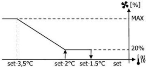
line
| Temperature | Value [%] | | :--- | :--- | | set-3.5°C | MAX | | set-2°C | 20% | | set-1.5°C | 20% | | set | [♣]text_image
17.0° 22.0° ✓ ×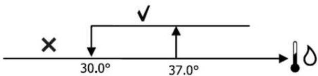
text_image
× 30.0° 37.0°line
| Condition | Percentage (%) | |---|---| | set | 20 | | set+0.5°C | 20 | | set+2°C | 100 |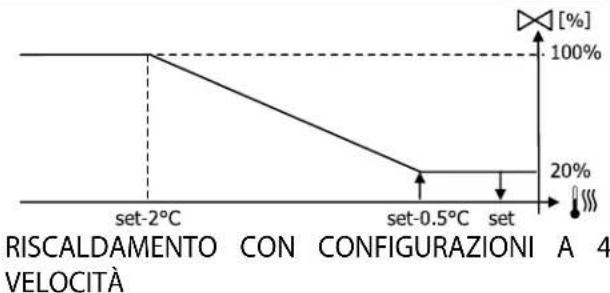
line
| Temperature | Percentage [%] | | ----------- | -------------- | | set-2°C | 100% | | set-0.5°C | 20% | | set | 20% |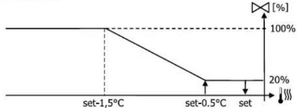
line
| Temperature | Percentage (%) | | :--- | :--- | | set-1.5°C | 100 | | set-0.5°C | 20 | | set | 20 |text_image
× 25.0° 30.0°text_image
On Off set-0,5° settext_image
37.0° 39.0°text_image
On 9° 10.0° Offtext_image
Vmin Set+0.5° Set+1.5° Vmedtext_image
Inib. Set-2.0° Set-1.5°text_image
✓ 10.0° × →FWV/L/M-D & FWZ/R/S-A
FWV/L/M-D & FWZ/R/S-A
text_image
Weather and health icons including sun, leaf, clock, crescent, no sign, lock, droplet, and heartbeattext_image
13:45 04/12/2019text_image
Grid of six icons with labels: gear, globe, refresh, question mark, and refresh symbol, arranged in a 2x2 grid.


text_image
Mobile app icons with labels for information, data, H2O, progress chart, and MIN/MAX metrics


text_image
17.0° 37.0°text_image
set set+0.5°C set+1.5°C set+2°C set+3°C 1 2 3Chauffage:
flowchart
graph TD
    A["set-3°C"] --> B["set-2°C"]
    B --> C["set-0.5°C"]
    C --> D["set"]
    style A fill:#f9f,stroke:#333
    style B fill:#f9f,stroke:#333
    style C fill:#f9f,stroke:#333
    style D fill:#f9f,stroke:#333
FONCTIONNEMENT AUTOMATIQUE POUR UNITÉ HY-DRONIQUE À 4 VITESSES ET VANNE(S) ON/OFF (OU ABSENTES):
flowchart
graph TD
    A["set-3°C"] --> B["set-2°C"]
    B --> C["set-1,5°C"]
    C --> D["set-0.5°C"]
    D --> E["set"]
    style A fill:#f9f,stroke:#333
    style B fill:#f9f,stroke:#333
    style C fill:#f9f,stroke:#333
    style D fill:#f9f,stroke:#333
    style E fill:#f9f,stroke:#333
FONCTIONNEMENT AUTOMATIQUE POUR UNITÉ HYDRONIQUE À 4 VITESSES ETVANNE(S) MODULANTE(S) :
-
Vitesse MINIMUM
-
Vitesse MINIMUM
-
Vitesse MOYENNE
-
Vitesse MOYENNE
-
Vitesse MAXIMUM
-
Vitesse MAXIMUM
sm. Vitesse superminimum
sm. Vitesse superminimum
line
| Condition | Value [%] | |---|---| | set | 20 | | set+0.5°C | 20 | | set+3°C | MAX |CHAUFFAGE AVEC CONFIGURATIONS À 3 VITESSES
line
| Temperature | Value (%) | | :--- | :--- | | set-3°C | MAX | | set-0.5°C | 20 | | set | 20 |text_image
17.0° 22.0° ✓ ×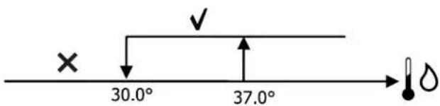
text_image
× 30.0° 37.0°text_image
× 25.0° 30.0°text_image
On Off set-0,5° settext_image
37.0° 39.0°text_image
On 9° 10.0° Offtext_image
Vmin Set+0.5° Set+1.5° Vmedtext_image
Inib. Set-2.0° Set-1.5°text_image
✓ 10.0° × →FWV/L/M-D & FWZ/R/S-A
FWV/L/M-D & FWZ/R/S-A
text_image
Weather and environmental icons including sun, leaf, clock, crescent, prohibition sign, lock, water droplet, and heartbeat waveformtext_image
13:45 04/12/2019text_image
Grid of six icons with labels: gear, speedometer, globe, refresh arrow, question mark, and refresh symbol


text_image
Mobile app icons with labels for information, data, H2O, and trend analysis functions


text_image
17.0° 37.0°text_image
set set+0.5°C set+1.5°C set+2°C set+3°C 1 2 3Heizen:
Heizen:
flowchart
graph TD
    A["set-3°C"] --> B["set-2°C"]
    B --> C["set-0.5°C"]
    C --> D["set"]
    style A fill:#f9f,stroke:#333
    style B fill:#f9f,stroke:#333
    style C fill:#f9f,stroke:#333
    style D fill:#f9f,stroke:#333
flowchart
graph TD
    A["set-3°C"] --> B["set-2°C"]
    B --> C["set-1.5°C"]
    C --> D["set-0.5°C"]
    D --> E["set"]
    style A fill:#f9f,stroke:#333
    style B fill:#f9f,stroke:#333
    style C fill:#f9f,stroke:#333
    style D fill:#f9f,stroke:#333
    style E fill:#f9f,stroke:#333
other
| Step | Value | |---|---| | set-3,5°C | 3 | | set-3°C | 2 | | set-2,5°C | 1 | | set-2°C | sm | | set-1.5°C | | | set | | The chart displays a discrete step pattern with arrows indicating direction along the x-axis. The right-side symbol (indicated by a leaf icon) appears at the bottom right corner. The y-axis is unlabeled but represents a quantitative or scaled metric. The label 'sm' appears near the bottom center of the step.line
| Condition | Value [%] | |---|---| | set | 20 | | set+0.5°C | 20 | | set+3°C | MAX |text_image
17.0° 22.0° ✓ ×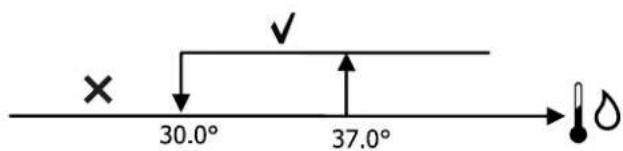
text_image
× 30.0° 37.0°text_image
× 25.0° 30.0°text_image
On Off set-0,5° settext_image
37.0° 39.0°text_image
On 9° 10.0° Offtext_image
Vmin Set+0.5° Set+1.5° Vmedtext_image
Inib. Set-2.0° Set-1.5° 10.0°FWV/L/M-D & FWZ/R/S-A
FWV/L/M-D & FWZ/R/S-A
text_image
Weather and health icons including sun, leaf, clock, crescent, no prohibition, lock, drop, and waveformtext_image
13:45 04/12/2019text_image
Grid of six icons with labels: gear, globe, refresh, question mark, and refresh symbol, arranged in a 2x2 grid.


text_image
Mobile app icons with labels for information, H2O, data analytics, and MAX metrics


text_image
17.0° 37.0°line
| Temperature | Percentage [%] | | ----------- | -------------- | | set | 20% | | set+0.5°C | 20% | | set+3°C | 20% |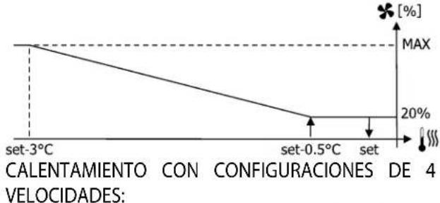
line
| Temperature | Capacity [%] | | ----------- | ------------ | | set-3°C | 100 | | set-0.5°C | 20 | | set | 20 |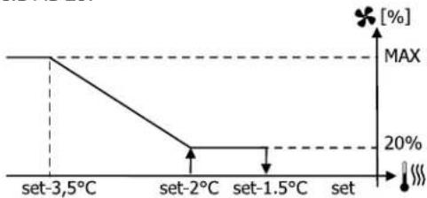
line
| Temperature | Value [%] | | :--- | :--- | | set-3.5°C | MAX | | set-2°C | 20% | | set-1.5°C | 20% | | set | [♣]text_image
17.0° 22.0°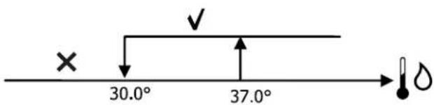
text_image
× 30.0° 37.0°text_image
× 25.0° 30.0°text_image
On Off set-0,5° settext_image
37.0° 39.0° ✓ ×text_image
On 9° 10.0° Offtext_image
Vmin Set+0.5° Set+1.5° Vmedtext_image
Inib. Set-2.0° Set-1.5°text_image
✓ 10.0° × →FWV/L/M-D & FWZ/R/S-A
FWV/L/M-D & FWZ/R/S-A
natural_image
Technical line drawing of a mechanical component with internal channels and mounting holes (no text or symbols)» 7
natural_image
Technical line drawing of a mechanical assembly with no visible text or symbols»6
natural_image
Technical line drawing of a mechanical assembly with an arrow indicating direction (no text or symbols present)» 8
natural_image
Technical line drawing of a mechanical component with internal helical structures and mounting holes (no text or symbols)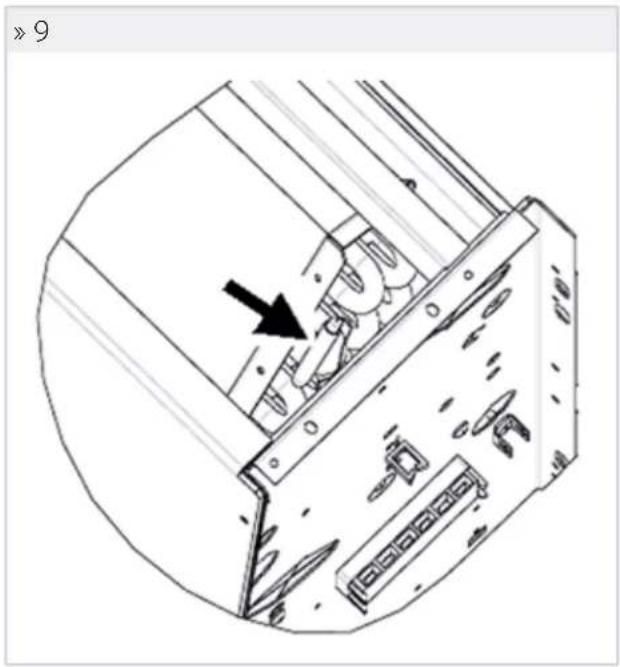
natural_image
Technical line drawing of a mechanical device with an arrow indicating a component (no text or symbols present)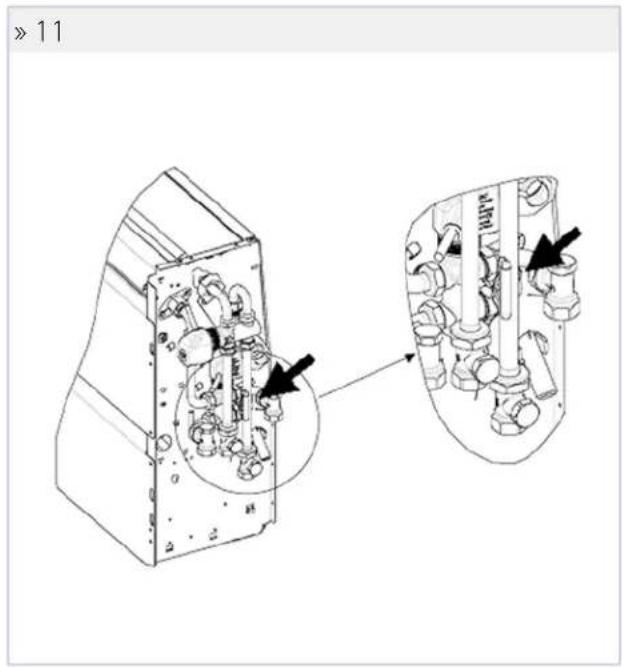
text_image
» 11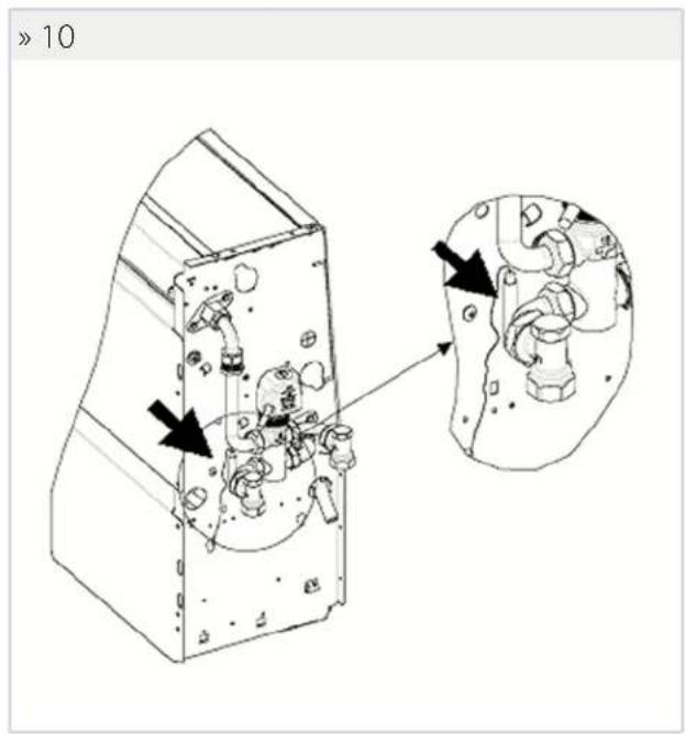
text_image
> 10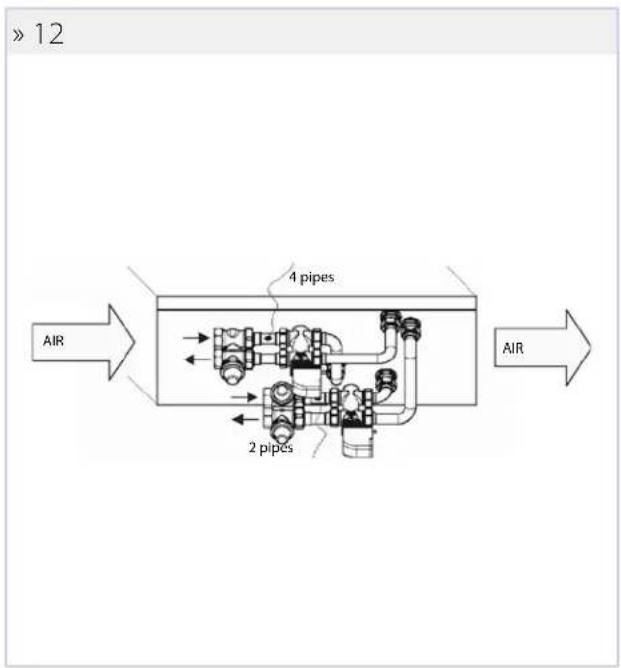
text_image
> 12 AIR 4 pipes 2 pipes AIR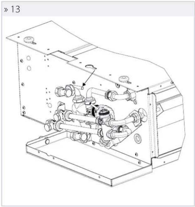
natural_image
Technical line drawing of a mechanical device with internal piping and housing (no text or symbols)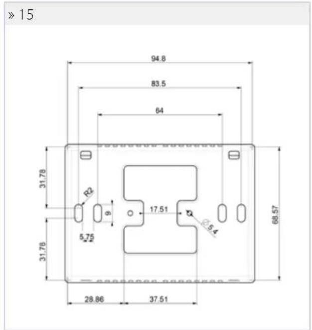
text_image
>15 94.8 83.5 64 31.78 R2 9 17.51 5.75 5.4 31.78 68.57 28.86 37.51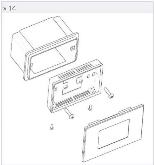
natural_image
Exploded view diagram of a device showing internal components and mounting holes (no text or symbols)
natural_image
Technical line drawing of a mechanical device with internal components and mounting bracket (no text or symbols)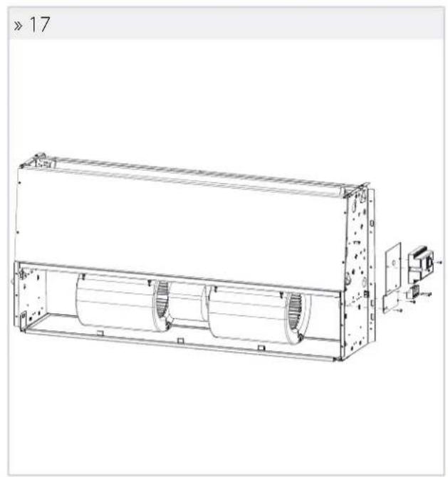
natural_image
Technical line drawing of a rectangular industrial machine with cylindrical components and mounting bracket (no text or symbols)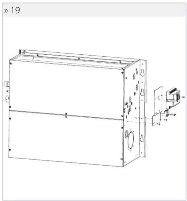
natural_image
Technical line drawing of a rectangular electronic device with mounting holes and internal components (no text or symbols)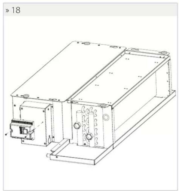
natural_image
Technical line drawing of an electronic device housing with internal components and mounting brackets (no text or symbols)» Schema elettrico generico EVO-2-TOUCH motore AC/EVO-2-TOUCH AC motor general wiring diagram/Schéma électrique general EVO-2-TOUCH AC moteur/Schaltplan generisch EVO-2-TOUCH AC Motor/Esquema eléctrico general EVO-2-TOUCH motor CA
text_image
SN SH SNH I1 I2 I3 I4 I5 IC +5 I6 I7 I8 I9 I10 IC IC SU SU R1 R2 R3 CA + - + - B A GND PS485 L H CON AC MOTOR RNG22 or 2 x 0,5 + SHIELD DISPLAY 230V L 50Hz... Collegamenti elettrici a cura dell'installatore/... Wirings made by supplier/... Branchements électriques incombant à l'installateur/... Stromanschlüsse seitens des Kunden/... Conexiones eléctricas a cargo del instalador
N: Neutro/ N: Neutral/ N: Neutre/ N: Neutral/ N: Neutro
L: Fase/ L: Phase/ L: Phase/ L: Phase/ L: Fase
F: Fusibile/ F: Fusible/ F: Fusible/ F: Sicherung/ F: Fusible
COM: Comune/ COM: Common/ COM: Commun/ COM: Gemeinsam/ COM: Común
CN: Morsettiera/ CN: Terminal board / CN: Bornier/ CN: Klemmenbrett/ CN: Caja de bornes
V4: Velocità massima motore/V4: Motor maximum speed /V4: Maximum vitesse moteur/V4: Höchstgeschwindigkeit/V4: Velocidad máxima motor
V3: Velocità media motore/V3: Motor medium speed/V3: Moteur medium vitesse /
V3: Mittlere Geschwindigkeit/V3: Velocidad media motor
V2: Velocità minima rotore/V2: Motor minimum speed/V2: Moteur minimum vitesse/V2: Mindestgeschwindigkeit/V2: Velocidad minima motor
V1: Velocità superminima motore/V1: Motor superminimum speed/V1: Moteur super minimum vitesse/V1: Super-Mindestgeschwindigkeit/V1: Velocidad sumamente baja motor
SUM/WIN: Contatto pulito per ESTATE/INVERNO remoto/SUM/WIN: No-voltage contact for remote SUMMER/WINTER/SUM/WIN: Contact libre pour ÉTÉ/HIVER à distance/ SUM/WIN: Potentialfreier Kontakt für Fern-SOMMER / WINTER/ SUM/WIN: Concto libre para VERANO/INVERNO remoto
ECONOMY: Contatto pulito per ECONOMY remoto/ECONOMY: No-voltage contact for remote ECONOMY/ECONOMY: Contact libre pour ECONOMY à distance/ECONOMYPotential/freier Kontakt für Fern-ECONOMY/ECONOMY: Contacto libre para ECONOMY remoto
FAN 0/10V: Ventilatore modulante 0/10V
/FAN 0/10V: Modulating fan 0/10V
N: Neutro/ N: Neutral/ N: Neutre/ N: Neutral/ N: Neutro
L: Fase/L: Phase/L: Phase/L: Phase/L: Fase
F: Fusibile/ F: Fusible/ F: Fusible/ F: Sicherung/ F: Fusible
COM: Comune/ COM: Common/ COM: Commun/ COM: Gemeinsam/ COM: Común
CN: Morsettiera/ CN: Terminal board / CN: Bornier/ CN: Klemmenbrett/ CN: Caja de bornes
SUM/WIN: Contatto pulito per ESTATE/INVERNO remoto/SUM/WIN: No voltage contact for remote SUMMER/WINTER/SUM/WIN: Contact libre pour ÉTÉ/HIVER à distance/ SUM/WIN: Potentialfreier Kontakt für Fern-SOMMER / WINTER/ SUM/WIN: Concto libre para VERANO/INVERNO remoto
ECONOMY: Contatto pulito per ECONOMY remoto/ECONOMY: No-voltage contact for remote ECONOMY/ECONOMY: Contact libre pour ECONOMY à distance/ECONOMYPotentialfreier Kontakt für Fern-ECONOMY/ECONOMY: Contacto libre para ECONOMY remoto
FAN 0/10V: Ventilatore modulante 0/10V
/FAN 0/10V: Modulating fan 0/10V