FWF05DAFN5V3 - Air Conditioning DAIKIN - Free user manual and instructions
Find the device manual for free FWF05DAFN5V3 DAIKIN in PDF.


User questions about FWF05DAFN5V3 DAIKIN
0 question about this device. Answer the ones you know or ask your own.
Ask a new question about this device
Download the instructions for your Air Conditioning in PDF format for free! Find your manual FWF05DAFN5V3 - DAIKIN and take your electronic device back in hand. On this page are published all the documents necessary for the use of your device. FWF05DAFN5V3 by DAIKIN.
USER MANUAL FWF05DAFN5V3 DAIKIN
Installation and operation manual

text_image
THE KEY FOR SMART INFORMATION Scan and find out moreFan coil units
natural_image
Technical line drawing of a mechanical housing or enclosure with mounting flanges and internal components (no text or symbols)FWF02D
FWF03D
FWF04D
FWF05D
Installation and operation manual Fan coil units
text_image
DAIKIN EUROPE N.V. Zandvoordestraat 300, B-8400 Ostende, Belgium Director Ostend, 1st of December 2022 Himomitsu Iwasaki DAIKIN DAIKIN4P702067-6C
| < A> TCF DT22-401 |
| < B> . |
| < C> - |
* as set out in and Judged positivity by according to the Certificate
**DKIKIN EUROPE N.V. is authorised to complete the Technical Construction File.
[Non-Text]
[Non-Text]
[Non-Text]
as amended,
S.1.2016/1101: Electrical Equipment (Safety) Regulations 2016
are in conformity with the following directive(s) or regulation(s), provided that the products are used in accordance with our instructions:
Daikin Europe N.V.
declores under its sole responsibility that the products to which this declaration relates:
^* =0.2,0.3,0.4,0.5),
UKCA – Safety declaration of conformity
Table of contents
1 About the documentation 4
1.1 About this document.... 4
1.2 Meaning of warnings and symbols 4
1.3 General....5
2 Specific installer safety instructions 5
For the installer 6
3 About the box 6
3.1 To unpack and handle the fan coil unit....6
3.2 To remove the accessories from the fan coil unit.... 6
4 About the units and options 6
4.1 Identification 6
4.1.1 Identification label: Fan coil unit.... 6
5 Unit installation 7
5.1 Preparing the installation site 7
5.2 Mounting the unit....7
5.2.1 To install the suspension bolts....7
5.2.2 To create ceiling opening....8
5.3 Water piping installation .... 9
5.3.1 Preparing water piping.... 9
5.3.2 Connecting water piping .... 9
5.4 Drain piping installation .... 10
5.4.1 Guidelines when installing the drain piping.... 10
5.4.2 Connecting the drain piping .... 11
5.5 Optional equipment installation .... 11
5.5.1 Preparing of optional equipment.... 11
5.5.2 Connecting the optional equipment .... 12
6 Electrical installation 14
6.1 Preparing electrical wiring 15
6.2 Connecting the electrical wiring.... 15
7 Configuration 17
7.1 Decorative panel setting.... 17
8 Commissioning 18
8.1 Checklist before commissioning.... 18
For the user 18
9 User safety instructions 18
9.1 Instructions for safe operation 18
10 About the system 18
11 Before operation 19
12 Operation 19
12.1 Operation range 19
13 Energy saving and optimum operation 19
14 Maintenance and service 19
14.1 Maintenance safety precautions.... 19
14.2 Precautions for maintenance and service 20
14.3 Cleaning the air filter, suction grille, air outlet and outside panels....20
14.3.1 To clean the air filter....20
14.3.2 To clean the suction grille....21
14.4 After a long stop period 21
14.5 Before a long stop period 21
14.6 After-sales service and warranty 21 14.6.1 Recommended maintenance and inspection 21 14.6.2 Shortened maintenance and replacement cycles 21
15 Troubleshooting 21
15.1 Relocation 22
16 Disposal 22
17 Technical data 23
17.1 Wiring diagram 23
17.2 Dimensions.... 24
18 Information requirements for ecodesign 26
1 About the documentation
1.1 About this document
Target audience
Authorised installers + end users

INFORMATION
This appliance is intended to be used in commercial, industrial or business environment.
Documentation set
This document is part of a documentation set. The complete set consists of:
- General safety precautions:
- Safety instructions that you must read before installing
- Format: Paper (in the box of the indoor unit)
- Indoor unit installation and operation manual:
- Installation and operation instructions
- Format: Paper (in the box of the indoor unit)
- Format: Digital files on https://www.daikin.eu. Use the search function 🔒 to find your model.
Latest revisions of the supplied documentation may be available on the regional Daikin website or via your dealer.
The original instructions are written in English. All other languages are translations of the original instructions.
Technical engineering data
- A subset of the latest technical data is available on the regional Daikin website (publicly accessible).
- The full set of latest technical data is available on the Daikin Business Portal (authentication required).
1.2 Meaning of warnings and symbols

DANGER
Indicates a situation that results in death or serious injury.

DANGER: RISK OF ELECTROCUTION
Indicates a situation that could result in electrocution.

DANGER: RISK OF BURNING/SCALDING
Indicates a situation that could result in burning/scalding because of extreme hot or cold temperatures.

WARNING
Indicates a situation that could result in death or serious injury.

CAUTION
Indicates a situation that could result in minor or moderate injury.

NOTICE
Indicates a situation that could result in equipment or property damage.

INFORMATION
Indicates useful tips or additional information.
Symbols used on the unit:
Symbol Explanation
| i |
Before installation, read the installation and operation manual, and the wiring instruction sheet.
1.3 General
If you are NOT sure how to install or operate the unit, contact your dealer.

WARNING
Improper installation or attachment of equipment or accessories could result in electrical shock, short-circuit, leaks, fire or other damage to the equipment. ONLY use accessories, optional equipment and spare parts made or approved by Daikin unless otherwise specified.

WARNING
Make sure installation, testing and applied materials comply with applicable legislation (on top of the instructions described in the Daikin documentation).

WARNING
This unit contains electrical and hot parts.

DANGER: RISK OF ELECTROCUTION
Do NOT operate the fan coil units with wet hands. An electrical shock may result.

WARNING
If the supply cord is damaged, it MUST be replaced by the manufacturer, its service agent or similarly qualified persons in order to avoid a hazard.

WARNING
Tear apart and throw away plastic packaging bags so that nobody, especially NOT children, can play with them. Possible consequence: suffocation.

DANGER: RISK OF ELECTROCUTION
Disconnect the power supply for more than 10 minutes, and measure the voltage at the terminals of main circuit capacitors or electrical components before servicing. The voltage MUST be less than 50 V DC before you can touch electrical components. For the location of the terminals, see the warning label for persons performing service and maintenance.

CAUTION
- Do NOT place any objects or equipment on top of the unit.
- Do NOT sit, climb or stand on the unit.

WARNING
This appliance can be used by children aged from 8 years and above and persons with reduced physical, sensory or mental capabilities or lack of experience and knowledge if they have been given supervision or instruction concerning use of the appliance in a safe way and understand the hazards involved.
Children SHALL NOT play with the appliance.
Cleaning and user maintenance SHALL NOT be made by children without supervision.

CAUTION
Do NOT touch the air inlet or aluminium fins of the unit.

CAUTION
Wear adequate personal protective equipment (protective gloves, safety glasses,...) when installing, maintaining or servicing the system.

WARNING
Provide adequate measures to prevent that the unit can be used as a shelter by small animals. Small animals that make contact with electrical parts can cause malfunctions, smoke or fire.

DANGER: RISK OF ELECTROCUTION
- Make sure that the system is earthed properly.
- Turn OFF the power supply before servicing.
- Install the switch box cover before turning ON the power supply.

CAUTION
- Check if the installation location can support the unit's weight. Poor installation is hazardous. It can also cause vibrations or unusual operating noise.
- Provide sufficient service space.
- Do NOT install the unit so that it is in contact with a ceiling or a wall, as this may cause vibrations.
2 Specific installer safety instructions
Always observe the following safety instructions and regulations.

WARNING
Make sure installation, servicing, maintenance and repair comply with instructions from Daikin and with applicable legislation and are executed ONLY by authorised persons.

WARNING
Installation shall be done by an installer, the choice of materials and installation shall comply with the applicable legislation. In Europe, EN378 is the applicable standard.

WARNING
- Do NOT use locally purchased electrical parts inside the product.
- Do NOT branch the power supply for the drain pump, etc. from the terminal block. This could result in electrical shock or fire.

WARNING
Keep the interconnection wiring away from copper pipes without thermal insulation as such pipes will be very hot.

CAUTION
For walls containing a metal frame or a metal board, use a wall embedded pipe and wall cover in the feed-through hole to prevent possible heat, electrical shock, or fire.

NOTICE
- Protect pipework from physical damage.
- Keep the pipework installation to a minimum.
For the installer
3 About the box
Keep the following in mind:
- At delivery, the unit MUST be checked for damage and completeness. Any damage or missing parts MUST be reported immediately to the claims agent of the carrier.
- Bring the packed unit as close as possible to its final installation position to prevent damage during transport.
- Prepare in advance the path along which you want to bring the unit to its final installation position.
3.1 To unpack and handle the fan coil unit
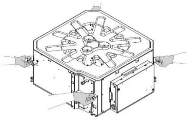
Use a sling of soft material or protective plates together with a rope when lifting the unit. This to avoid damage or scratches to the unit.
1 Lift the unit by holding onto the hanger brackets without exerting any pressure on other parts, especially on drain piping and thermal insulation.
natural_image
Technical line drawing of a mechanical assembly with multiple arms and components, no visible text or symbols
NOTICE
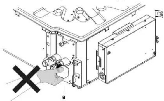
Do NOT lift the unit by the valve actuators (a).
text_image
Technical diagram showing a hand operating a device with labeled parts and a cross symbol indicating failure or disassembly.3.2 To remove the accessories from the fan coil unit
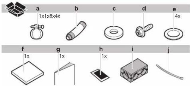
text_image
a 1x1x8x4x b c d e 4x f g h i j 1x 1x 1xa Metal clamp
b Drain hose
c Washer for hanger bracket
d Screw
e Gasket
f Large sealing pad for drain hose
g Installation and operation manual
h Thermal insulation for air purge
i Thermal insulation for valves (2 pipe: 1x and 4 pipe: 2x)
(*)
j Tie wrap for valve thermal insulation (2 pipe: 2x and 4 pipe: 4x) (*)
* Only models with factory mounted valve
4 About the units and options
4.1 Identification
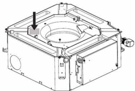
4.1.1 Identification label: Fan coil unit
Location
natural_image
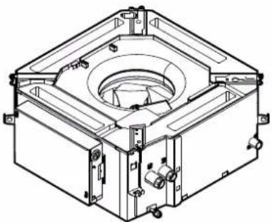
Technical line drawing of a mechanical housing or enclosure with mounting brackets and internal components (no text or symbols)Model identification
Example: FW F 02 D A T N 5 V3 --
| Code | Description |
| FW | Water fan coil unit |
| F | Cassette |
| D | Major model change (A to Z) |
| A | Minor change |
| T | 2 pipe |
| F | 4 pipe |
| N | Without valve |
| V | 3 way valve |
| T | 2 way valve |
| Code Description | |
| 5 Hendek factory | |
| V3 1 Ph / 50 Hz | / 230 V |
| - No option | |
| - Connection direction (no specific direction) | |
5 Unit installation
5.1 Preparing the installation site

NOTICE
The unit must be installed ≥2.5 m from the floor.

INFORMATION
The sound pressure level is less than 70 dBA.

CAUTION
Appliance NOT accessible to the general public. Install it in a secured area, protected from easy access.
This unit is suitable for installation in a commercial and light industrial environment.

NOTICE
Where installation from below is NOT possible, such as very high ceilings, access to the unit for installation and service should be possible from the top of the ceiling.
Select an installation site where the following conditions are fulfilled and that meets your customer approval.
- The space around the unit is adequate for maintenance and servicing. The space around the unit allows sufficient air circulation and air distribution. See space required for installation.

NOTICE
If the switch box (c) is facing the wall, leave a service distance of at least 600 mm and provide at least 1500 mm space from air inlet (b) and air outlet (a) for air circulation.
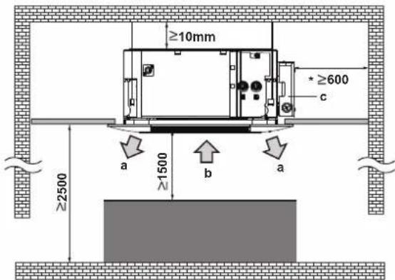
text_image
≥10mm ≥600 c a ≥2500 ≥1500 b a- Make sure the area is well ventilated. Do NOT block any ventilation openings.
- Make sure the installation site withstands the weight and vibration of the unit.
- Take care that in the event of a water leak, water cannot cause any damage to the installation space and surroundings.
- Choose a location where the operation noise or the hot/cold air discharged from the unit will not disturb anyone and the location is selected according the applicable legislation.
- Drainage. Make sure condensation water can be evacuated properly.
-
In places with weak reception, keep distances of 3 m or more to avoid electromagnetic disturbance of other equipment and use conduit tubes for power and transmission lines.
-
Fluorescent lights. When installing a wireless remote control (user interface) in a room with fluorescent lights, mind the following to avoid interference:
- Install the wireless remote control (user interface) as close as possible to the indoor unit.
• Install the indoor unit as far as possible from the fluorescent lights.
Do NOT install the unit in places often used as work place. In case of construction works (e.g. grinding works) where a lot of dust is created, the unit MUST be covered.
Do not install or operate the unit in rooms mentioned below.
- Places with mineral oil, or filled with oil vapour or spray, like in kitchens (plastic parts may deteriorate).
- Where corrosive gas like sulphurous gas exists. Copper tubing and brazed spots may corrode.
- Where the air contains high levels of salt, such as that near the coast and where voltage fluctuates a lot (e.g. in factories). Also in vehicles or vessels.
- In places where there is machinery that emits electromagnetic waves. Electromagnetic waves may disturb the control system, and cause malfunction of the equipment.
- In places where there is a risk of fire due to the leakage of flammable gases (example: thinner or gasoline), carbon fibre, ignitable dust.
- The unit can NOT be installed in a bathroom.
5.2 Mounting the unit
5.2.1 To install the suspension bolts
Use the pattern to determine the suspension bolt positions (upper part of the packing). Suspension bolt positions are indicated on the paper pattern. Holes can be drilled by putting the paper pattern on the ceiling.
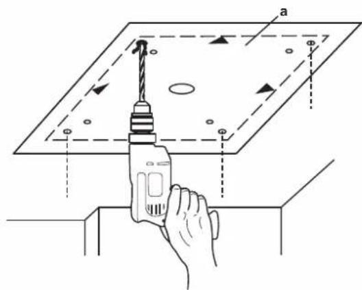
text_image
Diagram showing a hand using a drill to install a floor panel, with labeled components and directional arrows indicating movement.a Paper pattern for installation. (upper part of the packing)
- Ceiling strength. Check whether the ceiling is strong enough to support the weight of the unit. If there is a risk, reinforce the ceiling before installing the unit.
- For existing ceilings, use anchors.
- For new ceilings, use sunken inserts, sunken anchors or other field supplied parts.
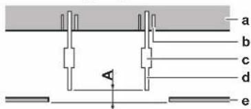
text_image
a b c d eA 50\~100 mm
a Ceiling slab
b Anchor
c Long nut or turnbuckle
d Suspension bolt
e Suspended ceiling
5 Unit installation
- Suspension bolts. Use M8\~M10 suspension bolts for installation. Attach the hanger bracket to the suspension bolt. Fix it securely using a nut and washer from the upper and lower sides of the hanger bracket.
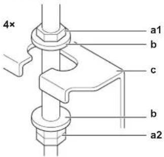
text_image
4x a1 b c b a2a1 Nut (field supply)
a2 Double nut (field supply)
b Washer (accessories)
c Hanger bracket (attached to the unit)
5.2.2 To create ceiling opening
Use the paper pattern (upper part of the packing) (a) to create ceiling opening according to the outlines specified on the paper pattern. Attach paper pattern to the unit using the four screws (d) from the accessory set and create the opening by referencing the ceiling opening line (c).
Make sure the unit and its hanger brackets (suspension) are centered (b) within the ceiling opening.
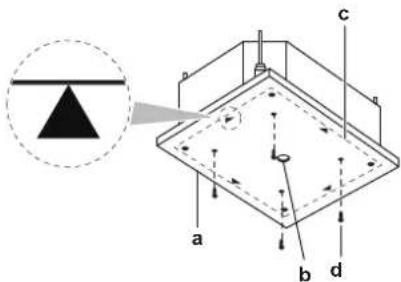
text_image
Technical diagram showing a structural element with labeled components (a, b, c, d) and an inset image of a triangular load or force distribution.a Paper pattern for installation (upper part of the packing)
b Centre of the ceiling opening
c Ceiling opening line
d Screws (accessories)

NOTICE
Create maximum 660 mm square opening in case of installation with BYFQ60B and 595 mm in case of installation with BYFQ60C. Otherwise, decorative panel and ceiling board can NOT overlap. If larger sizes are used, the sides should be covered with additional ceiling material.
| If A (mm)(a) | Then | ||
| B (mm)(a) | C (mm)(a) | ||
| BYFQ60B (Standard panel) | |||
| 585 (min) 57.5 | |||
| 660 (max) 42.5 20 | |||
| BYFQ60C (Design panel) | |||
| 585 (min) 17.5 | |||
| 595 (max) 10 12.5 | |||
(a) A: Ceiling opening
B: Distance between the unit and the ceiling opening
C: Overlap between the decoration panel and the suspended ceiling
- Level. Make sure the unit is level at all 4 corners using a level or a water-filled vinyl tube.
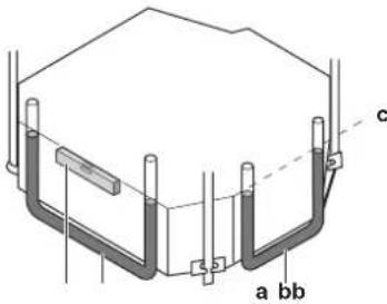
text_image
a bb ca Level
b Vinyl tube
c Water level

NOTICE
Do NOT install the unit tilted. Possible consequence: If the unit is tilted against the direction of the condensate flow (the drain piping side is raised), the float switch might malfunction and cause water to drip.
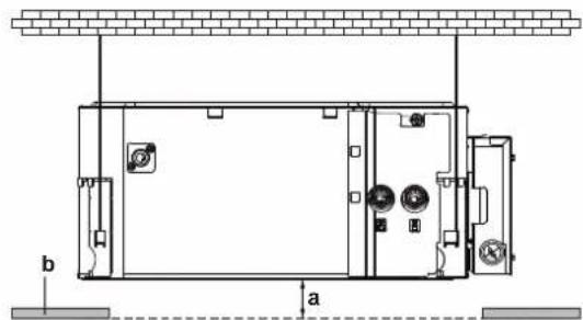
Adjust the distance between the panels in the vertical direction as follows:
natural_image
Technical line drawing of a mechanical or electrical enclosure with labeled components (a and b), no readable text or symbols present.a Vertical distance for ceiling material
b Ceiling board
| Panel type | a |
| BYFQ60B (Standard panel) | 25 mm |
| BYFQ60C (Design panel) 34 mm |
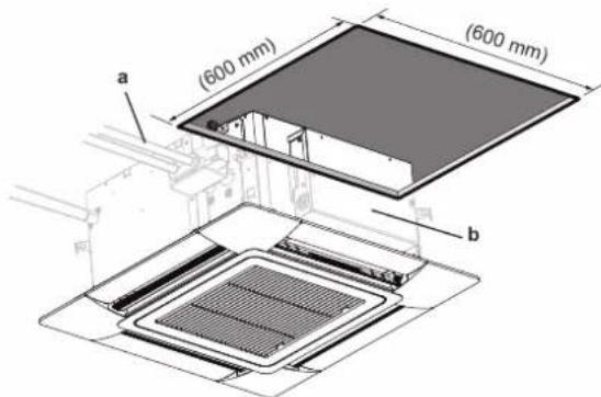
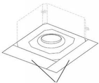
To create an opening in an existing monolithic ceiling board

NOTICE
It is necessary to provide a service space in the ceiling where the switch box and water pipes can be reached.
Below dimensions can be used as a reference for the service space or it can be determined by considering the position of the switch box (b) and water pipes (a) connections at the installation site.
text_image
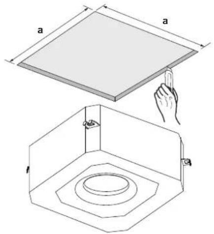
(600 mm) (600 mm) a bIf the unit must be installed in an existing monolithic ceiling board, please follow the following dimensions:
According to the models & panels combination:
| Type a (mm) | ||
| Standard Model BYFQ60B | Design Panel BYFQ60C | |
| No valve 600~660 595~600 | ||
| Factory mounted valve | 652~660 ≥652 A | (a) |
(a) A: Hang the unit from the suspension bolts, then adjust the size of the opening to be between 585-595 mm by adding extra ceiling material (b) so that the panel and ceiling board can overlap.
text_image
a a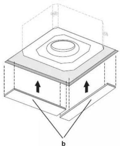
natural_image
3D diagram of a layered structure with arrows indicating direction, no text or symbols present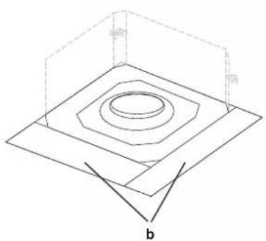
natural_image
Isometric diagram of concentric circles and nested squares with a labeled point 'b' (no text or symbols beyond label)5.3 Water piping installation
5.3.1 Preparing water piping
Before performing the water piping work, check the following points:
- The maximum water pressure is 1.6 MPa.
- The minimum water temperature is 5^ .
-
The maximum water temperature is 80°C.
-
Be sure to install components in the field piping that can withstand the water pressure and temperature.
- Provide adequate safeguards in the water circuit to ensure that the water pressure will never exceed the maximum allowable working pressure.
- Provide a proper drain for the pressure relief valve (if installed) to avoid any water from coming into contact with electrical parts.
- Provide shut-off valves at the unit so that normal servicing can be accomplished without draining the system.
- Provide drain taps at all low points of the system to permit complete draining of the circuit during maintenance or service to the unit.
- Provide air purge valves at all high points of the system. The valves shall be located at points which are easily accessible for servicing.
The unit is equipped with a water inlet and water outlet for connection to the water circuit. The water circuit must be provided by an installer and must comply with the applicable legislation.
- Pipework shall be protected from physical damage.

NOTICE
The unit is ONLY to be used in a closed water system. Application in an open water circuit can lead to excessive corrosion of the water piping.

NOTICE
Make sure water quality complies with EU directive 2020/2184.

NOTICE
Use of glycol is allowed, but the amount shall NOT exceed 40% of the volume. A higher amount of glycol may cause damage to the hydraulic components.
5.3.2 Connecting water piping

CAUTION
Always use valves to control water circulation in the unit. If the fan coil unit is off, but water keeps circulating in the unit, condensation will form on the unit and water may drip.

NOTICE
Make sure to insulate all piping. Any exposed piping might cause condensation.

DANGER: RISK OF BURNING/SCALDING
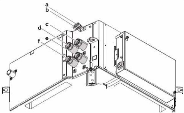
text_image
a b c d f ea Cooling air purge
b Heating air purge
c Hot water inlet (3/4" female BSP)
d Hot water outlet (3/4" female BSP)
e Cold water inlet (3/4" female BSP)
f Cold water outlet (3/4" female BSP)
5 Unit installation
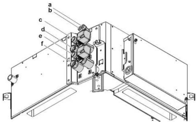
text_image
a b c d e fa Cooling air purge
b Heating air purge
c Hot water inlet (DN3/4")
d Hot water outlet (3/4" female BSP)
e Cold water inlet (DN3/4")
f Cold water outlet (3/4" female BSP)
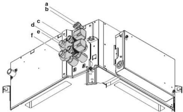
text_image
a b c d e fa Cooling air purge
b Heating air purge
c Hot water inlet (DN3/4")
d Hot water outlet (DN3/4")
e Cold water inlet (DN3/4")
f Cold water outlet (DN3/4")
To fill the water circuit
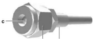
natural_image
3D mechanical component diagram showing a cylindrical shaft with hexagonal end and central hole, labeled 'c' (no text or symbols beyond label)b a
a Air purge valve
b Nut
c Springy core
During filling, it might not be possible to remove all air in the system. Remaining air can be removed during the first operating hours of the unit. The air can be removed from the unit through the manual air purge valve.
1 Open the air purge valve (refer to figure "Air purge valve") by turning the nut 2 times.
2 Push the springy core (refer to figure "Air purge valve") to let off superfluous air from the unit water circuit(s).
3 Tighten the nut.
4 Additional filling with water afterwards might be required (but never through the air purge valve).

NOTICE
Air in the water circuit can cause malfunctioning. During filling, it may not be possible to remove all the air from the circuit. Remaining air will be removed through the automatic air purge valves during the initial operating hours of the system. Additional filling with water afterwards may be required.

NOTICE
Make sure water quality complies with EU directive 2020/2184.

NOTICE
The air purge valve must be thermally insulated. Otherwise, water may drip with condensation. After the air is purged from the system, the air purge valve must be insulated with the thermal insulation (a) (from accessory set) so that its surface is completely covered as seen below.
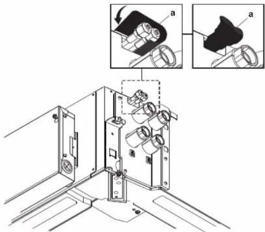
text_image
Technical diagram showing mechanical assembly with labeled parts and a close-up of a component being inserted into a housing.5.4 Drain piping installation
5.4.1 Guidelines when installing the drain piping
General guidelines
- Pipe length. Keep drain piping as short as possible.
- Pipe size. Keep the pipe size equal to or greater than that of the connecting pipe (vinyl pipe of 25 mm nominal diameter and 32 mm outer diameter).
- Slope. Make sure the drain piping slopes down (at least 1/100) to prevent air from being trapped in the piping. Use hanging bars as shown.
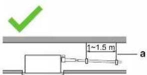
text_image
1~1.5 m aa Hanging bar
Allowed
Not allowed
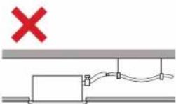
- Condensation. Take measures against condensation. Insulate the complete drain piping in the building.
- Combining drain pipes. You can combine drain pipes. Make sure to use drain pipes and T-joints with the correct gauge for the operating capacity of the units.
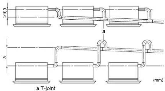
text_image
≥100 a A a T-joint (mm)- Rising piping. If necessary to make the slope possible, you can install rising piping.
- Drain hose inclination: 0\~75 mm to avoid stress on the piping and to avoid air bubbles.
- Rising piping: ≤300 mm from the unit, ≤630\~645 mm (depending on the decoration panel used) perpendicular to the unit.
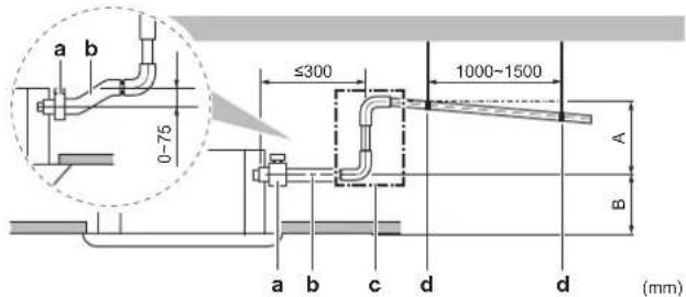
text_image
a b 0-75 ≤300 1000-1500 A B a b c d d (mm)A ≤645 mm: In case of installation with BYFQ60B ≤630 mm: In case of installation with BYFQ60C
B 205 mm: In case of installation with BYFQ60B 220 mm: In case of installation with BYFQ60C
a Metal clamp (accessory)
b Drain hose (accessory)
c Rising drain piping (vinyl pipe of 25 mm nominal diameter and 32 mm outer diameter) (field supply)
d Hanging bars (field supply)
Drain socket position
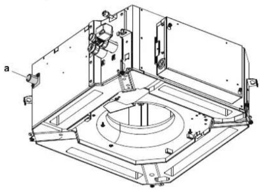
natural_image
Technical line drawing of a mechanical assembly with mounting brackets and a central circular component (no text or symbols)a Drain socket
5.4.2 Connecting the drain piping
To connect the drain piping

NOTICE
Incorrect connection of the drain hose might cause leaks, and damage the installation space and surroundings.
1 Push the drain hose as far as possible over the drain socket.
2 Tighten the metal clamp until the screw head is less than 4 mm from the metal clamp part.
3 Check for water leaks.
4 Wind the large sealing pad (= insulation) around the metal clamp and drain hose.
5 Connect the drain piping to the drain hose.
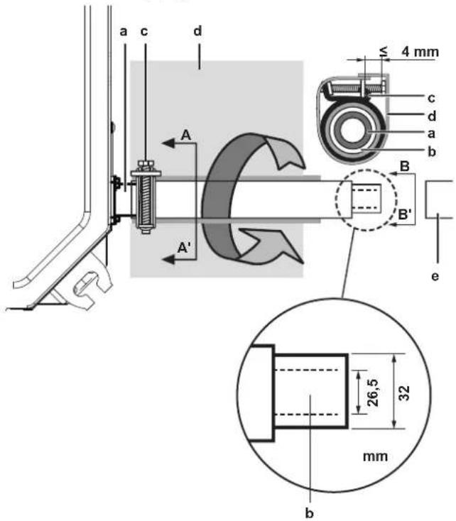
text_image
a c d ≤ 4 mm c d a b B B' e A' A 26,5 32 mm ba Drain socket (attached to the unit)
b Drain hose (accessory)
c Metal clamp (accessory)
d Large sealing pad (accessory)
e Drain piping (field supply)
When electrical wiring is finished already
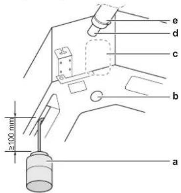
1 Start cooling operation.
2 Gradually pour approximately 1 l of water through the air discharge outlet, and check for leaks.
text_image
e d c b a ≥100 mma Plastic watering can
b Service drain outlet (with rubber plug). Use this outlet to drain water from the drain pan
c Drain pump location
d Drain socket
e Drain hose
5.5 Optional equipment installation
5.5.1 Preparing of optional equipment
- In case of installation with a fresh air intake kit. Install the fresh air intake kit always before installing the unit.
- Decoration panel. Install the decoration panel always after installing the unit.

INFORMATION
Optional equipment. When installing optional equipment, also read the installation manual of the optional equipment. Depending on the field conditions, it might be easier to install the optional equipment first.

NOTICE
After installing the decoration panel:
- Make sure there is no gap between the unit body and the decoration panel. Possible consequence: Air might leak and cause dew drop.
- Make sure no oil remains on the plastic parts of the decoration panel. Possible consequence: Degradation and damage of plastic parts.

NOTICE
In the case of using remote controller other than Daikin remote controllers, it should have the following features:
- Power supply 1 Ph, 230 V, 50 Hz. If a controller with a different power supply rating is used, the power supply can NOT be common with the unit. It must be powered separately.
- Valve control: 230 V, 50 Hz ON/OFF
- Fan control: 0-10 V DC output for fan.
- Fan speeds should be controllable in ≤0.5 V DC steps.
| Mandatory equipment Identification code | |
| Standard panel BYFQ60B3W1 | |
| Design panel (white) BYFQ60C2W1W | |
| Design panel (silver) BYFQ60C2W1S | |
| Adaptor EKRP1CAS5A | |
| Optional equipment Identification code | |
| Long-life replacement filter KAF44 | 1C60 |
| Air discharge outlet sealing parts | KDBHQ44C60 |
| Fresh air intake kit KDDQ44XA60 | |
| Valves Identification code | |
| ON/OFF valve (2 way)(a) | EKWV2V3W5A |
| ON/OFF valve (3 way)(a) | EKWV3V3W5A |
(a) In case of 4 pipe models it is necessary to order 2 sets.
5.5.2 Connecting the optional equipment
Connecting the decorative panel cable
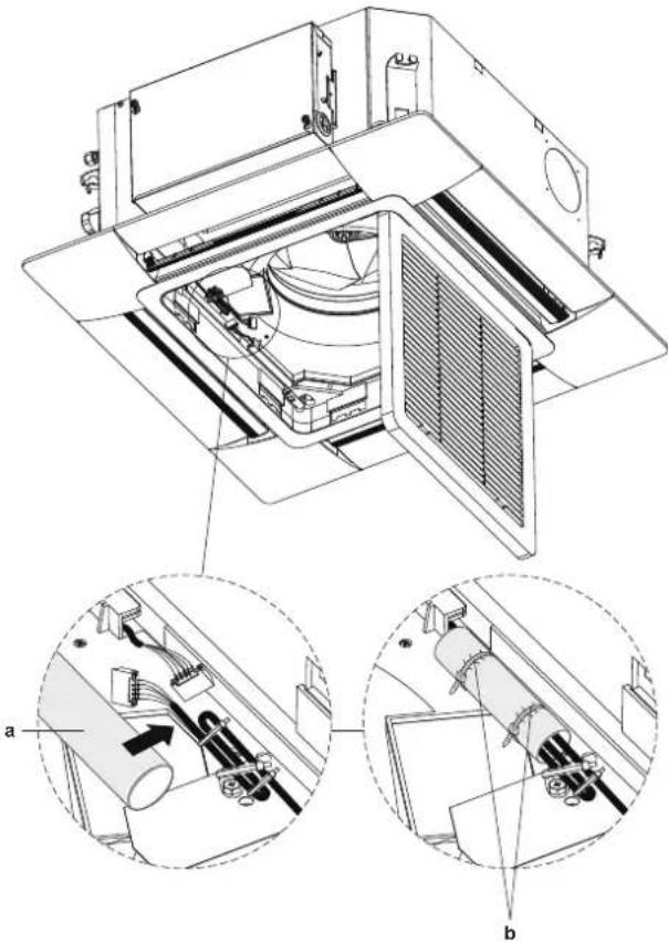
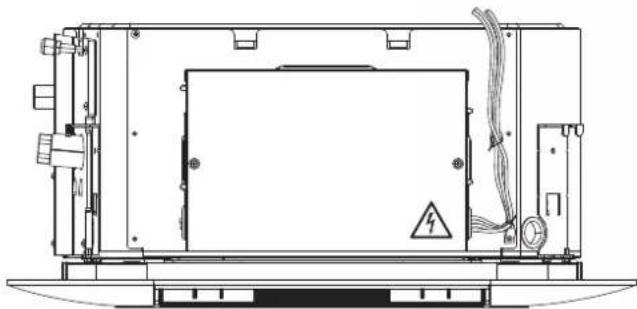
In case of a standard decorative panel (BYFQ60B), the panel cable is fixed to the inlet on the unit as shown in the figure. When connecting the panel, do not forget to attach the protective silicone tube (b) (decorative panel accessory set) on the connection as shown in the figure.
natural_image
Technical diagram of an air conditioning unit with internal components and labeled parts (a and b), showing internal wiring and housing layout.a Silicone glass tube (in decorative panel accessory set)
b Tie wrap (in decorative panel accessory set)
To install the on-off valve kits

NOTICE
The PCB connection of the valves is only required when the Daikin ON/OFF valve kit (EKWV2V3W5A/EKWV3V3W5A) is used.
Technical specifications of the valves
| Kvs value | Max. operation pressure PN (bar) | Actuator power supply |
| 2.8 | 16 | 1 Ph, 230 V,50-60 Hz, NC(Normally closed) |
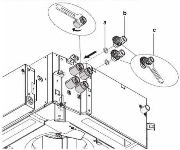
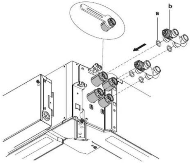
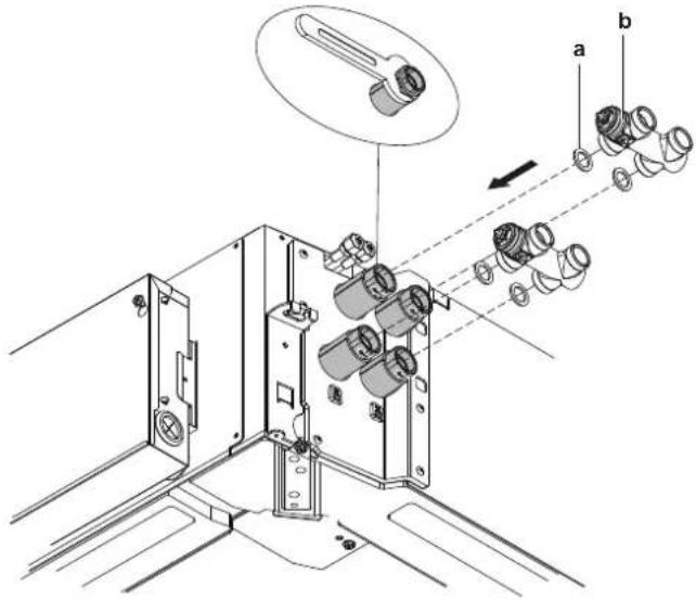
1 Gasket (a) and valve body (b)
2-way on off valve kit
2-way valve body should be held with a wrench (c).
text_image
Technical diagram showing assembly of mechanical components with labeled parts a, b, and c3-way on off valve kit
text_image
Technical diagram showing assembly of mechanical components with labeled parts a and b, including a magnified inset of a wrench.2 Actuators (d)
2-way on off valve kit
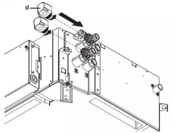
text_image
d3-way on off valve kit
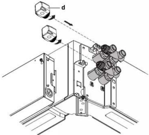
text_image
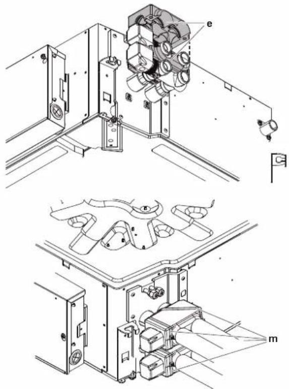
Technical diagram showing mechanical assembly with labeled component 'd' and directional arrows indicating motion or force3 Valve insulations (e) and tie wraps (m)
2-way on off valve kit
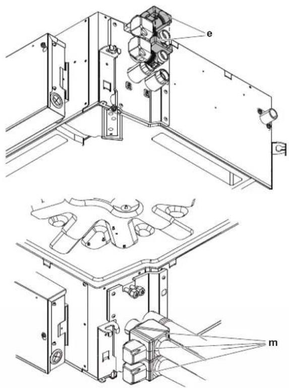
text_image
Technical diagram showing mechanical assembly with labeled parts (e, m) and numbered components3-way on off valve kit
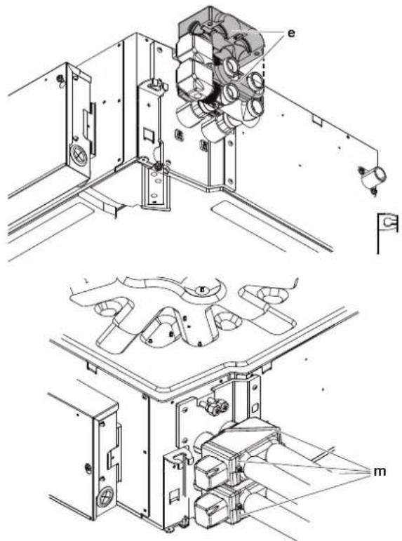
text_image
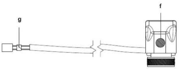
Technical diagram showing mechanical assembly with labeled components and exploded views4 The actuator surface (f) and the end of cable (g) are colour-coded to prevent switching the cables of the heating and cooling valves.
6 Electrical installation
text_image
g f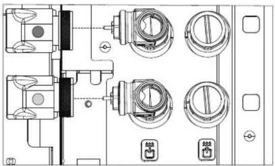
natural_image
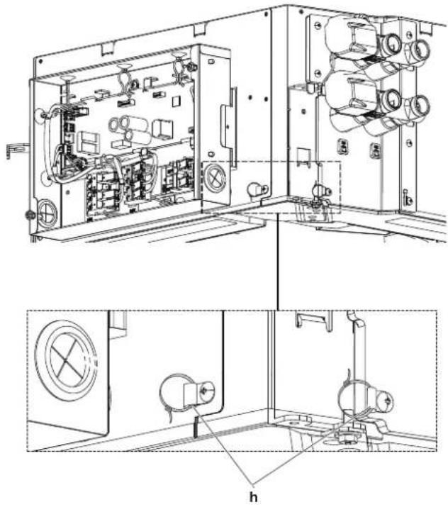
Technical line drawing of a mechanical assembly with multiple circular components and mounting holes (no text or symbols)5 Tie wraps (h). The tie wraps (i) are tightened.
natural_image
Technical line drawing of an electrical enclosure with internal components and a close-up view of the interior (no text or symbols)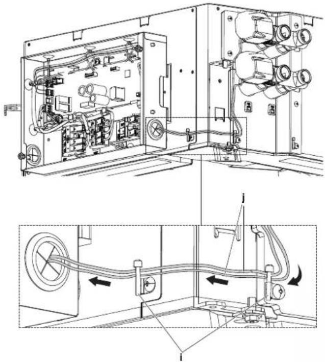
natural_image
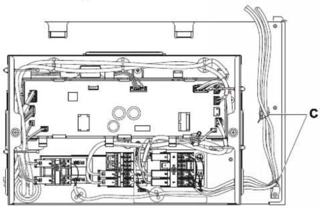
Technical line drawing of an electrical enclosure with internal components and wiring, showing no text or symbols.6 Cable holders (k). Connect the cooling valve cable (blue label) to the X32A socket and the heating valve cable to the X37A socket (l).
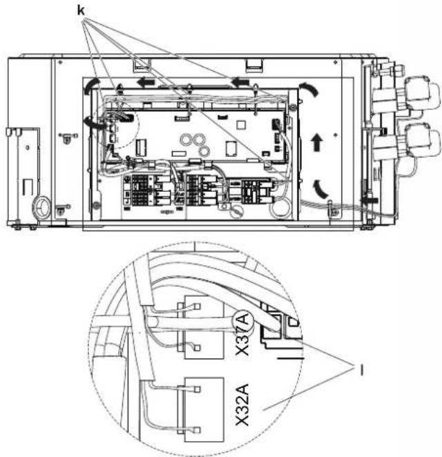
text_image
k X37A X32A I6 Electrical installation

DANGER: RISK OF ELECTROCUTION

WARNING
ALWAYS use multicore cable for power supply cables.

WARNING
Use an all-pole disconnection type breaker with at least 3 mm between the contact point gaps that provides full disconnection under overvoltage category III.
6.1 Preparing electrical wiring

WARNING
All field wiring and components MUST be installed by a licensed electrician and MUST comply with the applicable legislation.

DANGER: RISK OF ELECTROCUTION

WARNING
A main switch or other means for disconnection, having a contact separation in all poles, MUST be incorporated in the fixed wiring in accordance with the applicable legislation.

CAUTION
- When connecting the power supply: connect the earth cable first, before making the current-carrying connections.
- When disconnecting the power supply: disconnect the current-carrying cables first, before separating the earth connection.
- The length of the conductors between the power supply stress relief and the terminal block itself MUST be as such that the current-carrying wires are tautened before the earth wire is in case the power supply is pulled loose from the stress relief.

WARNING
- After finishing the electrical work, confirm that each electrical component and terminal inside the electrical components box is connected securely.
- Make sure all covers are closed before starting up the unit.

WARNING
Do NOT apply any permanent inductive or capacitance loads to the circuit without ensuring that this will NOT exceed the permissible voltage and current permitted for the equipment in use.

NOTICE
The equipment described in this manual may cause electronic noise generated from radio-frequency energy. The equipment complies to specifications that are designed to provide reasonable protection against such interference. However, there is no guarantee that interference will not occur in a particular installation.
It is therefore recommended to install the equipment and electric wires in such a way that they keep a proper distance from stereo equipment, personal computers, etc.

DANGER: RISK OF ELECTROCUTION
- Turn OFF all power supply before removing the fan coil unit terminal cover when connecting electrical wiring or touching electrical parts.
- Disconnect the power supply for more than 10 minutes, and measure the voltage at the terminals of main circuit capacitors or electrical components before servicing. The voltage MUST be less than 50 V DC before you can touch electrical components. For the location of the terminals, see the wiring diagram.
- Do NOT touch electrical components with wet hands.
- Do NOT leave the unit unattended when the terminal cover is removed.

WARNING
- ONLY use copper wires.
- Make sure the field wiring complies with the applicable legislation.
- All field wiring MUST be performed in accordance with the wiring diagram supplied with the product.
- NEVER squeeze bundled cables and make sure they do NOT come into contact with the piping and sharp edges. Make sure no external pressure is applied to the terminal connections.
- Make sure to install earth wiring. Do NOT earth the unit to a utility pipe, surge absorber, or telephone earth. Incomplete earthing may cause electrical shock.
- Make sure to install the required fuses or circuit breakers.
- Make sure to install an earth leakage protector. Failure to do so may cause electrical shock or fire.
6-1 Field wiring specifications
| 2 Pipe 4 Pipe | ||||||||
| Capacity | 02 | 03 | 04 | 05 | 02 | 03 | 04 | 05 |
| Maximum operating current (A) | 0,75 | 0.77 | 0,99 | 1,88 | 0,67 | 0,73 | 0,94 | 1,85 |
| Maximum operating current (A) with valves(a) | 0,82 | 0,84 | 1,06 | 1,95 | 0,74 | 0,81 | 1,02 | 1,92 |
| Recommended overcurrent fuse (A) | 5 | |||||||
| Phase | 1 | |||||||
| Frequency (Hz) | 50 | |||||||
| Voltage (V) | 230 | |||||||
| Voltage tolerance (%) | ±10 | |||||||
| Wire size (cross section mm2) | ≥1.5 | |||||||
| Earth leakage circuit breaker | Must comply with applicable legislation | |||||||
(a) Mentioned current is only for Daikin valves.
6.2 Connecting the electrical wiring

DANGER: RISK OF ELECTROCUTION

WARNING
ALWAYS use multicore cable for power supply cables.

WARNING
Use an all-pole disconnection type breaker with at least 3 mm between the contact point gaps that provides full disconnection under overvoltage category III.

NOTICE
Precautions when laying power wiring:
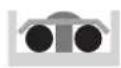
√
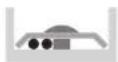
×
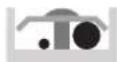
×
- Do NOT connect wiring of different thicknesses to the power terminal block (slack in the power wiring may cause abnormal heat).
- When connecting wiring which is the same thickness, do as shown in the figure above.
- For wiring, use the designated power wire and connect firmly, then secure to prevent outside pressure being exerted on the terminal board.
- Use an appropriate screwdriver for tightening the terminal screws. A screwdriver with a small head will damage the head and make proper tightening impossible.
- Over-tightening the terminal screws may break them.

NOTICE
- Follow the wiring diagram (delivered with the unit, located at the inside of the service cover).
- For instructions on how to connect the optional equipment, see the installation manual delivered with the optional equipment.
- Make sure the electrical wiring does NOT obstruct proper reattachment of the service cover.
It is important to keep the power supply and the transmission wiring separated from each other. In order to avoid any electrical interference the distance between both wirings should ALWAYS be at least 50 mm.

NOTICE
Be sure to keep the power line and transmission line apart from each other. Transmission wiring and power supply wiring may cross, but may NOT run parallel.
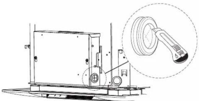
1
natural_image
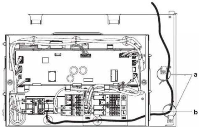
Technical line drawing of a mechanical device with a magnified inset showing a cable or connector (no text or symbols present)2 Cable clamps (a) and protection rubber (b). First connect the 0-10 V DC fan modulation cable to the X3M terminal.
text_image
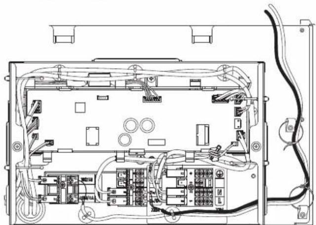
Technical diagram of an electronic device showing internal components and wiring, labeled with parts a and b.3 Connect the AC heating and signal cables from the controller to the X2M terminal.
natural_image
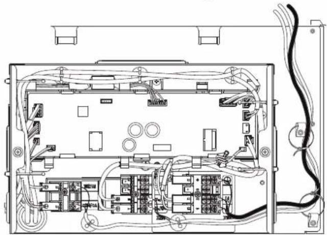
Technical line drawing of an internal electronic device casing with visible circuitry and wiring (no text or labels)4 Connect the power supply cables (L, N, Earth) to the lower part of the X1M terminal as shown in the figure.
natural_image
Technical line drawing of an electrical enclosure with exposed wiring and internal components (no text or labels)5 Connect the L, N and Earth for power supply of the remote controller to the upper part of the X1M terminal.
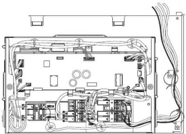
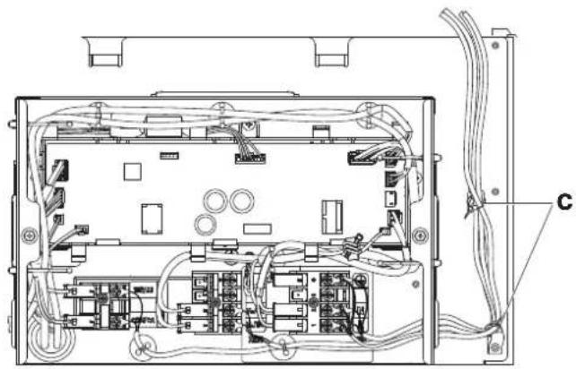
natural_image
Technical line drawing of an internal electronic device casing with visible circuitry and wiring (no text or labels)6 Cable clamps (c).
natural_image
Technical line drawing of an electrical enclosure with visible wiring and components (no text or symbols)7

natural_image
Technical line drawing of an electrical enclosure with warning symbol and grounding device (no text or labels)7 Configuration
7.1 Decorative panel setting
Make the following field settings so that they correspond with the actual installation setup and with the needs of the user:
- Design decoration panel (if applicable)
- Air flow direction

INFORMATION
In case the flaps operate automatically:
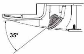
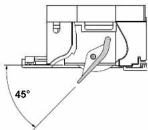
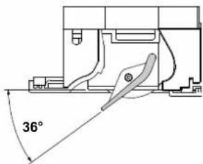
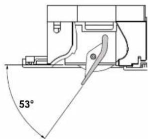
When the fan starts to operate, the flaps open completely and then remain in the set position. Check the below table for appropriate angle settings.
When the fan stops to operate including thermo off, the flaps open completely and then close completely.

NOTICE
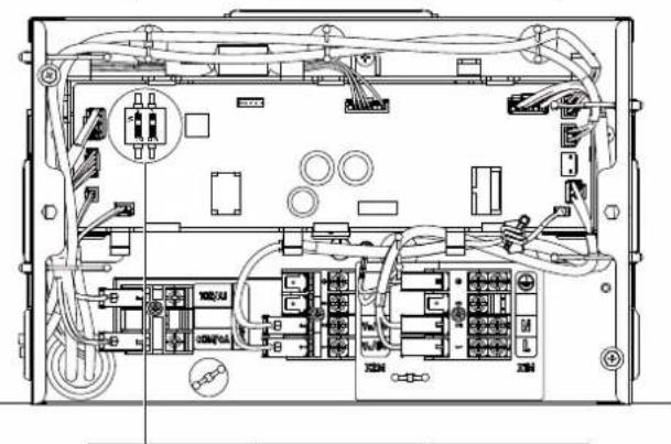
Make sure that the dip switch setting is correct according to panel type, otherwise panel will not work properly.
Setting: Air flow direction and design panel

NOTICE
If the flaps are required to open and close automatically, the decorative panel cable must be connected to the PCB. Otherwise, the flaps must be adjusted manually. (Refer to "5.5.2 Connecting the optional equipment" [▶ 12])

NOTICE
The "Adaptor (EKRP1CAS5A)" is mandatory option for PCB connection of the "Design Panel (BYFQ60C)"

NOTICE
Flap angle can only be adjusted by the dip switch on the PCB.
The flap positions of the decorative panels can be adjusted using the dip switch on the PCB. Please see the 4 different flap position options in the table.
| Panel type Option | ||||
| a b c d | ||||
| Standard (BYFQ60B) | Fully open 35" | --- | ||
| Design (BYFQ60C) | - 36° | 45° | Fully open | 53" |
natural_image
Technical line drawing of an electronic device rear panel with internal components and wiring (no text or labels)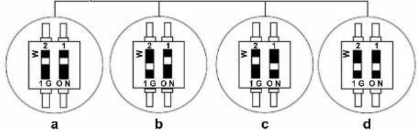
text_image
W 2 1 1 G O N a W 2 1 1 G O N b W 2 1 1 G O N c W 2 1 1 G O N da
text_image
35°c
text_image
45°b
text_image
36°d
text_image
53°8 Commissioning
8 Commissioning

NOTICE
Do NOT interrupt the test run.
8.1 Checklist before commissioning
1 After the installation of the unit, check the items listed below.
2 Close the unit.
3 Power up the unit.

You read the complete installation instructions, as described in the installer reference guide.

The indoor units are properly mounted.
| There are NO missing phases or reversed phases. | |
| The system is properly earthed and the earth terminals are tightened. | |
| The fuses or locally installed protection devices are installed according to this document, and have NOT been bypassed. | |
| The power supply voltage matches the voltage on the identification label of the unit. | |
| There are NO loose connections or damaged electrical components in the switch box. | |
| There are NO damaged components or squeezed pipes on the inside of the indoor and outdoor units. | |
| The correct pipe size is installed and the pipes are properly insulated. |
For the user
9 User safety instructions
Always observe the following safety instructions and regulations.
9.1 Instructions for safe operation

CAUTION
Do NOT insert fingers, rods or other objects into the air inlet or outlet. When the fan is rotating at high speed, it will cause injury.

CAUTION: Pay attention to the fan!
It is dangerous to inspect the unit while the fan is running.
Make sure to turn OFF the main switch before executing any maintenance task.

CAUTION
After a long use, check the unit stand and fitting for damage. If damaged, the unit may fall and result in injury.

CAUTION
It is unhealthy to expose your body to the air flow for a long time.

CAUTION
NEVER touch the internal parts of the controller.

DANGER: RISK OF ELECTROCUTION
To clean the air conditioner or air filter, be sure to stop operation and turn all power supplies OFF. Otherwise, an electrical shock and injury may result.

WARNING
Keep any required ventilation openings clear of obstructions.

WARNING
Stop operation and shut OFF the power if anything unusual occurs (burning smells etc.).
Leaving the unit running under such circumstances may cause breakage, electrical shock or fire. Contact your dealer.

WARNING
NEVER touch the air outlet or the horizontal blades while the swing flap is in operation. Fingers may become caught or the unit may break down.

WARNING
Do NOT place a flammable spray bottle near the air conditioner and do NOT use sprays near the unit. Doing so may result in a fire.

WARNING
Before operating the unit, be sure the installation has been carried out correctly by an installer.

WARNING
The appliance shall be stored so as to prevent mechanical damage and in a well-ventilated room without continuously operating ignition sources (e.g. open flames, an operating gas appliance, or an operating electric heater). The room size shall be as specified in the General safety precaution.
10 About the system

WARNING
Do NOT modify, disassemble, remove, reinstall or repair the unit yourself as incorrect dismantling or installation may cause an electrical shock or fire. Contact your dealer.

NOTICE
Do NOT use the system for other purposes. In order to avoid any quality deterioration, do NOT use the unit for cooling precision instruments, food, plants, animals, or works of art.

NOTICE
For future modifications or expansions of your system:
A full overview of allowable combinations (for future system extensions) is available in technical engineering data and should be consulted. Contact your installer to receive more information and professional advice.
11 Before operation

WARNING
This unit contains electrical and hot parts.

WARNING
Before operating the unit, be sure the installation has been carried out correctly by an installer.

CAUTION
NEVER expose little children, plants or animals directly to the airflow.
This operation manual is for the following systems with standard control. Before initiating operation, contact your dealer for the operation that corresponds to your system type and mark. If your installation has a customised control system, ask your dealer for the operation that corresponds to your system.
Operation modes:
- Heating and cooling (air to air).
- Fan only operation (air to air).
This operation manual offers a non-exhaustive overview of the main functions of the system.
For more information about the user interface, see the operation manual of the installed user interface.
12 Operation
12.1 Operation range

NOTICE
When unit starts to operate, it runs at a low speed for a certain period before it reaches set point. This is not a malfunction.
The following conditions are standard operating limits. For different conditions, please consult the dealer.
| Mode Condition Air | temperature limit, (DB/WB) | Water temperature limit, (in/out) | Water delta T, ΔT | |
| Cooling (°C) | Min. 15/12 | 5 5/8 3 to 10 | ||
| Max. | 33/26 | 18/28 | ||
| Heating (°C) | Min. 18/15 | 45/40 | 5 to 20 | |
| Max. | 25/15 | 80/75 | ||
13 Energy saving and optimum operation
Observe the following precautions to ensure the system operates properly.
- Adjust the air outlet properly and avoid direct air flow to room inhabitants.
- Adjust the room temperature properly for a comfortable environment. Avoid excessive heating or cooling.
- Prevent direct sunlight from entering a room during cooling operation by using curtains or blinds.
- Ventilate often. Extended use requires special attention to ventilation.
- Keep doors and windows closed. If the doors and windows remain open, air will flow out of your room causing a decrease in the cooling or heating effect.
- Be careful NOT to cool or heat too much. To save energy, keep the temperature setting at a moderate level.
- NEVER place objects near the air inlet or the air outlet of the unit. Doing so may cause a reduced heating/cooling effect or stop operation.
- Condensation may form if the humidity is above 80% or if the drain outlet gets blocked.

NOTICE
Do NOT use the system for other purposes. In order to avoid any quality deterioration, do NOT use the unit for cooling precision instruments, food, plants, animals, or works of art.

CAUTION
Do NOT operate the system when using a room fumigation-type insecticide. Chemicals could collect in the unit, and endanger the health of people who are hypersensitive to chemicals.
14 Maintenance and service
14.1 Maintenance safety precautions

DANGER: RISK OF BURNING/SCALDING

DANGER: RISK OF ELECTROCUTION

NOTICE
Keep the air filter clean and check the airflow rate periodically.

WARNING
- Before carrying out any maintenance or repair activity, ALWAYS switch off the circuit breaker on the supply panel.
- Make sure you do NOT touch a conductive section.
- Do NOT rinse the outside of the unit. This may cause electric shocks or fire.
To clean the outside of your fan coil unit:
1 Switch off the fan coil unit.
2 Clean the outside of the fan coil unit with a soft cloth.

CAUTION
- Do NOT obstruct the air outlet or inlet of the unit in any way.
- Do NOT place damp or wet clothing on the air outlet grille of the unit.
- Do NOT pour liquids inside the equipment.
Never clean your fan coil unit with:
- any aggressive chemical solvent,
- water hotter than 50°C.
For maintenance of your fan coil unit, contact your installer or service company.
14.2 Precautions for maintenance and service

NOTICE
NEVER inspect or service the unit by yourself. Ask a qualified service person to perform this work. However, as end user, you may clean the air filter, suction grille, air outlet and outside panels.

WARNING
NEVER replace a fuse with a fuse of a wrong ampere ratings or other wires when a fuse blows out. Use of wire or copper wire may cause the unit to break down or cause a fire.

CAUTION
After a long use, check the unit stand and fitting for damage. If damaged, the unit may fall and result in injury.

NOTICE
Do NOT wipe the controller operation panel with benzine, thinner, chemical dust cloth, etc. The panel may get discoloured or the coating peeled off. If it is heavily dirty, soak a cloth in water-diluted neutral detergent, squeeze it well and wipe the panel clean. Wipe it with another dry cloth.

CAUTION
Before accessing terminal devices, make sure to interrupt all power supply.

NOTICE
When cleaning the heat exchanger, make sure to remove the switch box, fan motor, drain pump and float switch. Water or detergent might deteriorate the insulation of electronic components and result in burnout of these components.

WARNING
Be careful with ladders when working in high places.
14.3 Cleaning the air filter, suction grille, air outlet and outside panels

CAUTION
Turn off the unit before cleaning the air filter, suction grille, air outlet and outside panels.

NOTICE
- Do NOT scrub firmly when washing the blade with water. Possible consequence: The surface sealing peels off.
Clean with a soft cloth. If it is difficult to remove stains, use water or a neutral detergent.
14.3.1 To clean the air filter
When to clean the air filter:
- Rule of thumb: Clean every 6 months. If the air in the room is extremely contaminated, increase the cleaning frequency.
- If the dirt becomes impossible to clean, change the air filter (= optional equipment).
How to clean the air filter:

NOTICE
Do NOT use water of 50^ C or higher. Possible consequence: Discoloration and deformation.
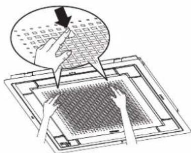
1 Open the suction grille.
Standard panel:
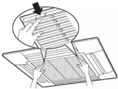
text_image
Diagram illustrating a document editing or writing process with hand-drawn steps and a magnified view of the text being edited.Design panel:
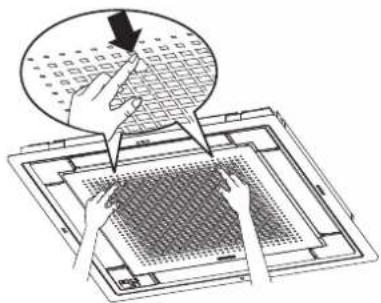
text_image
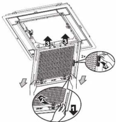
Diagram showing hands installing a grid on a device, with a magnified view highlighting the grid structure.2 Remove the air filter.
Standard panel:
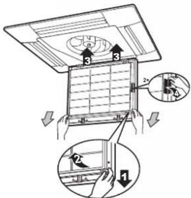
text_image
Diagram illustrating a mechanical assembly with numbered components and directional arrows, likely illustrating a folding or assembly process.Design panel:
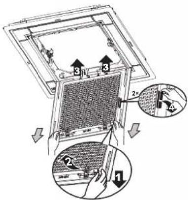
text_image
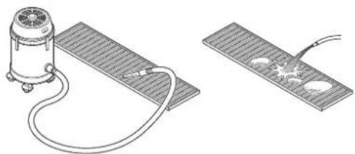
Technical diagram showing a grid installation with numbered components and directional arrows indicating process flow.3 Clean the air filter. Use a vacuum cleaner or wash with water. If the air filter is very dirty, use a soft brush and neutral detergent.
natural_image
Illustration of a vacuum cleaner connected to a solar panel and a separate flat panel with wires (no text or symbols)4 Dry the air filter in the shadow.
5 Reattach the air filter and close the suction grille.
14.3.2 To clean the suction grille

NOTICE
Do NOT use water of 50^ C or higher. Possible consequence: Discoloration and deformation.
1 Open the suction grille.
2 Remove the suction grille.
Standard panel:
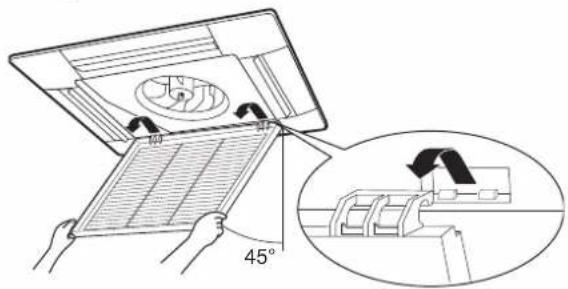
text_image
45°Design panel:
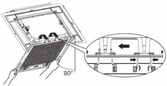
text_image
90° A E3 Remove the air filter.
4 Clean the suction grille. Wash with a soft bristle brush, and water or neutral detergent. If the suction grille is very dirty, use a typical kitchen cleaner, leave it on for 10 min, then wash it with water.
5 Reattach the air filter (step 3 in reverse order).
6 Reattach the suction grille and close it (step 2 and 1 in reverse order).
14.4 After a long stop period
E.g., at the beginning of the season.
- Check and remove everything that might be blocking inlet and outlet vents of indoor units and outdoor units.
- Clean air filters and casings of indoor units (see "14.3.1 To clean the air filter" [▶ 20] and To clean the air outlet and outside panels).
14.5 Before a long stop period
E.g., at the end of the season.
- Let the indoor units run in fan only operation for about half a day in order to dry the interior of the units. Refer to About cooling, heating, fan only, and automatic operation for details on fan only operation.
- Turn off the power. The user interface display disappears.
- Clean air filters and casings of indoor units (see "14.3.1 To clean the air filter" [▶20] and To clean the air outlet and outside panels).
14.6 After-sales service and warranty
14.6.1 Recommended maintenance and inspection
Since dust collects when using the unit for several years, performance of the unit will deteriorate to some extent. As taking apart and cleaning interiors of units requires technical expertise and in order to ensure the best possible maintenance of your units, we recommend to enter into a maintenance and inspection contract on top of normal maintenance activities. Our network of dealers has access to a permanent stock of essential components in order to keep your unit in operation as long as possible. Contact your dealer for more information.
When asking your dealer for an intervention, always state:
- The complete model name of the unit.
- The manufacturing number (stated on the nameplate of the unit).
- The installation date.
- The symptoms or malfunction, and details of the defect.

WARNING
Do NOT modify, disassemble, remove, reinstall or repair the unit yourself as incorrect dismantling or installation may cause an electrical shock or fire. Contact your dealer.
14.6.2 Shortened maintenance and replacement cycles
Shortening of "maintenance cycle" and "replacement cycle" needs to be considered in following situations:
The unit is used in locations where:
- Heat and humidity fluctuate out of the ordinary.
- Power fluctuation is high (voltage, frequency, wave distortion, etc.) (the unit cannot be used if power fluctuation is outside the allowable range).
- Bumps and vibrations are frequent.
- Dust, salt, harmful gas or oil mist such as sulphurous acid and hydrogen sulfide may be present in the air.
- The machine is started and stopped frequently or operation time is long (sites with 24 hour air-conditioning).
Recommended replacement cycle of wear parts
| Component Inspectioncycle | Maintenance cycle(replacements and/orrepairs) |
| Air filter 1 year5years | |
| High efficiency filter | |
| Fuse | |
| Pressure containing parts |

INFORMATION
Damage due to taking apart or cleaning interiors of units by anyone other than our authorised dealers may not be included in the warranty.
15 Troubleshooting
If one of the following malfunctions occur, take the measures shown below and contact your dealer.
The system MUST be repaired by a qualified service person.
| Malfunction Measure | |
| If a safety device such as a fuse, a breaker or an earth leakage breaker frequently actuates or the ON/OFF switch does not properly work. | Turn off the main power switch. |
| If water leaks from the unit. Stop the operation. | |
| The operation switch does not work well. | Turn off the power. |
If the system does NOT operate properly except for the above mentioned cases and none of the above mentioned malfunctions is evident, investigate the system in accordance with the following procedures.
| Malfunction Measure | |
| If the system does not operate at all. | Check if there is no power failure. Wait until power is restored.Check if no fuse has blown or breaker is activated. Change the fuse or reset the breaker if necessary. |
| The system operates but cooling or heating is insufficient. | Check if air inlet or outlet of outdoor or indoor unit is not blocked by obstacles. Remove any obstacles and make sure the air can flow freely.Check if the air filter is not clogged (see "14.3.1 To clean the air filter" [▶20]).Check the temperature setting.Check the fan speed setting on your user interface.Check for open doors or windows. Close doors and windows to prevent wind from coming in.Check if there are too many occupants in the room during cooling operation. Check if the heat source of the room is excessive.Check if direct sunlight enters the room. Use curtains or blinds.Check if the air flow angle is proper. |
If after checking all above items, it is impossible to fix the problem yourself, contact your installer and state the symptoms, the complete model name of the unit (with manufacturing number if possible) and the installation date.
15.1 Relocation
Contact your dealer to remove and reinstall the entire unit. Moving units requires technical expertise.
16 Disposal
- Units are marked with the following symbol:
This means that electrical and electronic products may NOT be mixed with unsorted household waste. Do NOT try to dismantle the system yourself: dismantling the system, treatment of the refrigerant, of oil and of other parts MUST be done by an authorised installer and MUST comply with applicable legislation.
Units MUST be treated at a specialised treatment facility for reuse, recycling and recovery. By ensuring this product is disposed of correctly, you will help to prevent potential negative consequences for the environment and human health. For more information, contact your installer or local authority.

NOTICE
Do NOT try to dismantle the system yourself: dismantling of the system, treatment of the refrigerant, oil and other parts MUST comply with applicable legislation. Units MUST be treated at a specialised treatment facility for reuse, recycling and recovery.
After installation, the installer is obliged to verify correct operation. In case something is wrong with the unit and it does not operate, contact your local dealer.
Use the proper tool to remove the screws. The product can be disassembled as shown below.
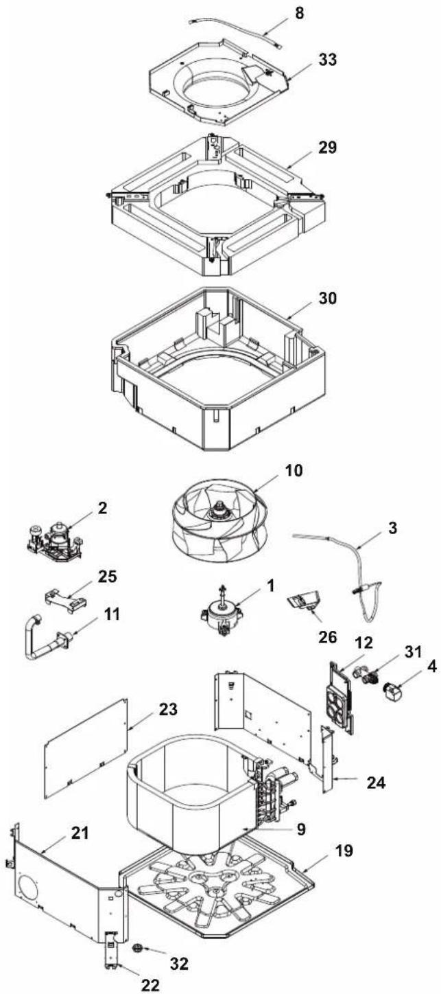
text_image
Exploded view diagram of a mechanical device with numbered components for identification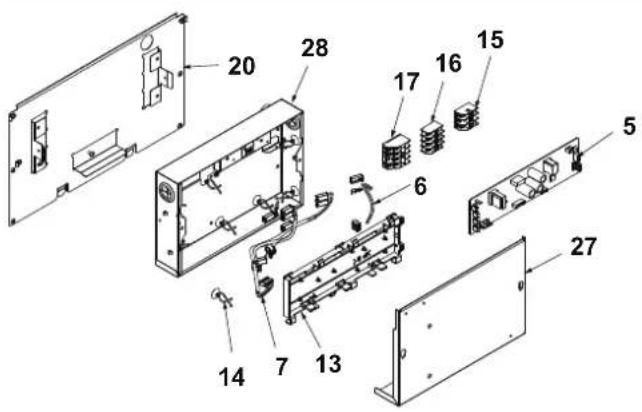
text_image
Exploded view diagram of an electronic device with numbered components for identification| Materials Item | |
| Electrical part 1, 2, 3, 4, 5, 6, 7, 8 | |
| Aluminium (fin) + copper (tube) + galvanised steel (plate) + brass +plastic foam | 9 |
| Plastic 10, 11, 12, 13, 14, 32 | |
| Plastic + metal 15, 16, 17, 18 | |
| Galvanised steel 19 ~ 27 | |
| Galvanised steel + plastic 28 | |
| Brass 31 | |
| EPS (expanded polystyren foam) + metal + plastic foam | 29, 30 |
17 Technical data
A subset of the latest technical data is available on the regional Daikin website (publicly accessible). The full set of latest technical data is available on the Daikin Business Portal (authentication required).
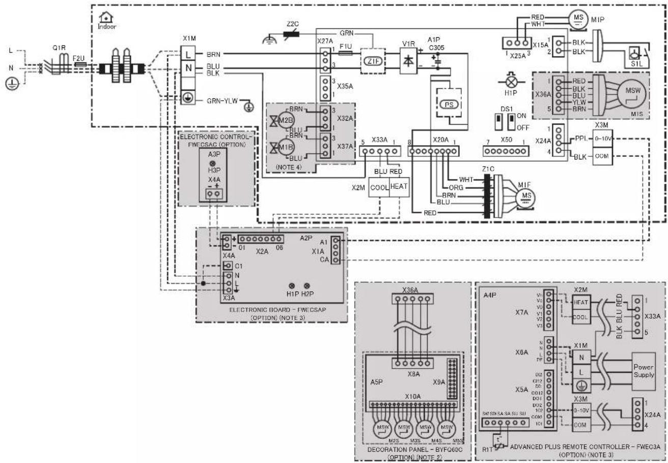
17.1 Wiring diagram
flowchart
graph TD
    subgraph "Indoor"
        L --> Q1R
        N --> Q2U
        Q1R --> F2U
        F2U --> X1M
        X1M --> BRN
        BRN --> BLU
        BLU --> BLK
        BLK --> GRN-YLW
        GRN-YLW --> X35A
        X35A --> Z1P
        Z1P --> V1R
        V1R --> A1P
        A1P --> C305
        C305 --> H1P
        H1P --> DS1
        DS1 --> ON_OFF
        ON_OFF --> X36A
        X36A --> BLK
        BLK --> YLW
        YLW --> BRN
        BRN --> M1S
        M1S --> X3M
        X3M --> BLK
        BLK --> COM
    end

    subgraph "Electronic Control"
        ELECTRONIC_CONTROL-FWECSAC(OPTION)" --> A3P
        A3P --> H3P
        H3P --> X4A
        X4A --> C1
        C1 --> N
        N --> X3A
        X3A --> H1P H2P
    end

    subgraph "Electronic Board - FEWSAP (OPTION) (NOTE 3)"
        ELECTRONIC_BOARD_-_FEWSAP["EXTRONIC BOARD - FEWSAP (OPTION) (NOTE 3)"]
    end

    subgraph "DECORATION PANEL - BYF060C (OPTION) (NOTE 2)"
        ELECTRONIC BOARD - FEWSAP --> X36A
        X36A --> A4P
        A4P --> X7A
        X7A --> X6A
        X6A --> X5A
        X5A --> W1SINSA-SA-SU-SU
        W1SINSA-SA-SU-SU --> COM
        COM --> R1T
        R1T --> ADVANCED_PLUS_REMOTE_CONTROLLER-FWE03A
    end

    subgraph "ADVANCED PLUS REMOTE CONTROLLER - FWE03A (OPTION) (NOTE 3)"
        ELECTRONIC BOARD - FEWSAP --> X36A
        X36A --> A4P
        A4P --> X7A
        X7A --> X6A
        X6A --> X5A
        X5A --> W1SINSA-SA-SU-SU
        W1SINSA-SA-SU-SU --> COM
        COM --> R1T
    end
Notes:
1 ☐☐☐☐: Terminal block ☐☐: Connector = ☐☐☐☐ =: Field wiring.
2 X36A is connected when the decorative panel kit is being used.
3 Please follow the manual of the external remote controller for the wiring.
4 X32A and X37A can only be connected to the specified Daikin valve options.
Colours:
BLK Black
BLU Blue
BRN Brown
GRN Green
PPL Purple
ORG Orange
RED Red
WHT White
YLW Yellow
17 Technical data
Legend for wiring diagrams:
Indoor unit:
| A1P Main PCB | |
| A2P Electronic board (FWECSAP) | |
| A3P Electronic control (FWECSAC) | |
| A4P Advanced plus remote controller(FWEC3A) | |
| A5P Adaptor PCB | |
| C305 Capacitor | |
| F1U Fuse (6.3 A, 250 V) | |
| F2U Field fuse | |
| DS1 Dip switch on PCB | |
| H1P Flashing lamp | |
| M1P Motor (drain pump) | |
| M1S Swing motor | |
| M2S | |
| M3S | |
| M4S | |
| M5S | |
| M1F Motor (DC fan) | |
| S1L Float switch | |
| V1R Diode bridge | |
| Q1R Earth leakage breaker | |
| X1M Terminal block (power supply) | |
| X2M Terminal block (remote control signal and valve terminal) | |
| X3M Terminal block (fan modulation) | |
| Z1F Noise filter | |
| Z1C Ferrite core | |
| Z2C Ferrite core | |
| PS Switching power supply | |
| M1B Heating actuator | |
| M2B Cooling actuator | |
PCB connections:
| X15A Float switch | |
| X20A BLDC motor | |
| X24A Fan modulation | |
| X25A Drain pump | |
| X27A Power supply | |
| X32A Cooling valve | |
| X33A R/C signal and valve | |
| X35A Electrical heater | |
| X36A Stepping motor (Decoration panel) | |
| X37A Heating valve | |
| X50A Serial communication | |
Terminal connections:
| 0-10 V 0-10 V DC fan modulation | |
| COM Common | |
| HEAT Heating signal | |
| COOL Cooling signal | |
External remote controller:
| H1P Status lamp | |
| H2P Network lamp | |
| A1/102 0-10 V DC fan modulation | |
| CA/COM Common | |
| O6/VH Heating signal | |
| 05/VC Cooling signal | |
| L | Phase |
| N | Neutral |
| PE | Protective earth |
| R1T Thermistor (air) | |
Connector for optional parts:
| X1A Connector (fan modulation wires) |
| X2A Connector (valve wires) |
| X3A Connector (power supply for modbus) |
| X4A Connector (power supply for display) |
| X5A Connector (fan modulation wires) |
| X6A Connector (power supply for display) |
| X7A Connector (valve wires) |
| X8A Connector (naked PCB X36A) |
| X9A Connector (BYCQ140E panel wire) |
| X10A Connector(BYFQ60C panel wire) |
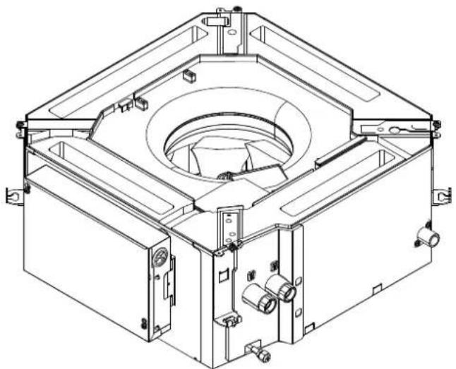
17.2 Dimensions
Overview
natural_image
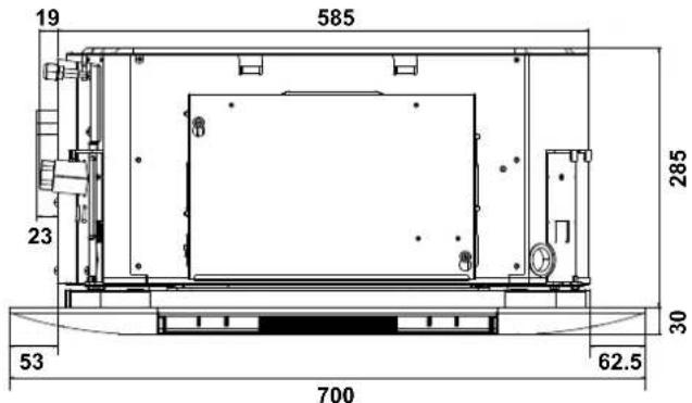
Technical line drawing of a mechanical housing or enclosure with internal components and mounting brackets (no text or symbols)Side views with standard panel (mm)
text_image
19 585 23 285 30 53 62.5 700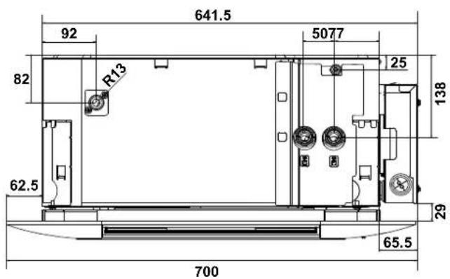
text_image
641.5 92 5077 82 R13 25 138 62.5 29 65.5 700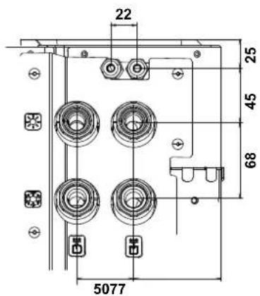
text_image
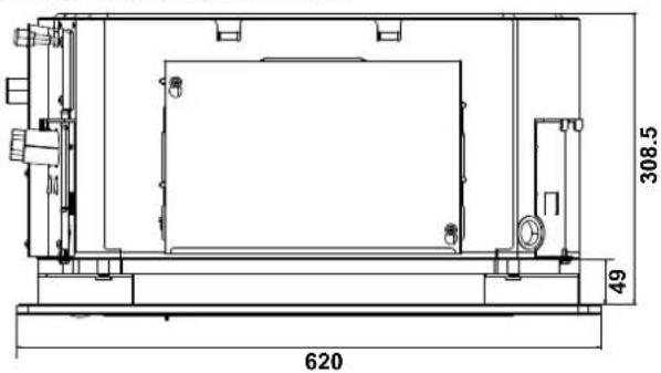
22 25 45 68 5077Side views with design panel (mm)
text_image
308.5 49 620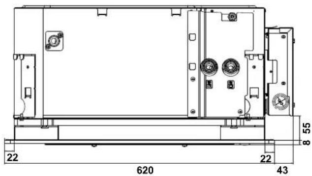
text_image
22 620 43 8 55 22 4318 Information requirements for ecodesign
| Prated,c | Prated,c | Prated,h | Pelec | LWA |
| GB Cooling capacity (sensible)D Kühlleistung (sensibel)F Puissance de rafraichissement (sensible)NL Koelcapaciteit (voelbaar)E Capacidad de refrigeración (sensibilidad)I Capacità di raffreddamento (sensibile)GR Atóðosn ψύξης (αιθητή)P Capacidade de arrefecimento (sensível)TR Soğutma kapasitesi (duyarli)RUS Хладопроизводительность (явная)S Kylningskapacitet (känslig)N Avkjølingskapasitet (følbar)CZ Chladici výkon (citelný)HR Kapacitet hlađenja (osjetljivo)H Hütési teljesítmény (érzékeny)RO Capacitate de răcire (fâră dezumidificare)SLO Moč hlajenja (zaznavna)SK Kapacita chladenia (üčelná)BG Kapacитет на охлаждане (практически)PL Wydajność chłodnicza (jawna)DK Kelekapacitet (mærkbart)FIN Jäähdytyskapasiteetti (järkevä)EST Jahutusvõimsus (möödukas)LV Dzesëšanas kapacităte (jütamā)LT Vésinimo galia (tikroji)AL Kapaciteti i ftohjes (sensibël)SRB Kapacitet hlađenja (opipljiv) | GB Cooling capacity (latent)D Kühlleistung (latent)F Puissance de rafraîchissement (latente)NL Koelcapaciteit (latent)E Capacidad de refrigeración (latente)I Capacità di raffreddamento (latente)GR Atóðosn ψύξης (λανθάνουσα)P Capacidade de arrefecimento (latente)TR Soğutma kapasitesi (glzil)RUS Хладопроизводительность (скрытая)S Kylningskapacitet (latent)N Avkjølingskapasitet (latent)CZ Chladici výkon (latentni)HR Kapacitet hlađenja (latentno)H Hütési teljesítmény (látens)RO Capacitate de răcire (cu dezumidificare)SLO Moč hlajenja (latentna)SK Kapacita chladenia (latentná)BG Kapacитет на охлаждане (потенциален)PL Wydajność chłodnicza (utajona)DK Kelekapacitet (skjult)FIN Jäähdytyskapasiteetti (latentti)EST Jahutusvõimsus (latentne)LV Dzesëšanas kapacităte (latentă)LT Vésinimo galia (latentinė)AL Kapaciteti i ftohjes (në gjendje gjumi)SRB Kapacitet hlađenja (latentan) | GB Heating capacityD HeizleistungF Puissance de chauffageNL VerwarmingscapaciteitE Capacidad de calefacciónI Capacità di riscaldamentoGR Atóðosn ґєрмавоңςP Capacidade de aquecimentoTR Isitma kapasitesI RUS ТеплопроизводительностьS VärmekapacitetN OppvarmlingskapasitetCZ Topný výkonHR Kapacitet grijanjaH Fütési teljesítményRO Capacitate de încălzireSLO Moč ogrevanjaSK Výkon ohrevuBG Отоплителна мощностPL Wydajność grzewczaDK VarmekapacitetFIN LämmitystehoEST KüttevõimsusLV Apsildes kapacităteLT Šildymo galiaAL Kapaciteti i ngrohjesSRB Kapacitet grejanja | GB Total electric power inputD Elektrische GesamtleistungsaufnahmeF Entrée électrique totaleNL Totaal opgenomen vermogenE Potencia eléctrica de entrada totalI Potenza eletrica totale assorbitaGR Συνολική ηλεκτρική ισχύς εισόδουP Entrada de potência elétrica totalTR Çekilen toplam elektrik gűcűRUS Общаяпотребляемая электрическая мощностьS Total effektingångN Total elektrisk strømeffektCZ Celkový elektrický príkonHR Ukupna primljena snaga električne energijeH Teljes âramforrás-bemenetRO Consum total de putereSLO Skupna vhodna električna močSK Celkový elektrický príkonBG Обща входяща електрическа мощностPL Całkowita pobierana energia elektrycznaDK Total elektrisk strømforsyningFIN Sähkötehon kokonaistuloEST Kogu elektriline sisendvõimsusLV Kopėjä elektriskä eiejas jaudaLT Bendroji elektros vartojamoji galiaAL Konsumi total i energjisė elektrikeSRB Ukupna ulazna električna snaga | GB Sound power level (per speed setting, if applicable)D Schallleistungspegel (je Geschwindlgkeitsinstellung, falls zutreffend)F Niveau de puissance sonore (par réglage de vitesse, le cas échéant)NL Geluidsvermognenniveau (per snelheidsinstelling, indien van toepassing)E Nivel de potencia acústica (según ajuste de velocidad, si corresponde)I Livello di potenza sonora (per velocità impostata, se applicabile)GR Στάθμη ηχητικής ισχύος (ανάρύθμιση τοχύτητας, εφόσον διατίδεται)P Nivel de potência acústica (por regulação de velocidade, se aplicável)TR Ses gűcű sevlyesi (műmkünse hiz ayari başina)RUS Уровень звукового давления (согласно настройке скорости, если применимо)S Ljudeffektsnivå (per hastighetsinställning, om tillämpligt)N Nivå på lydeffekt (per hastighetsinnstilling, hvis tilgjengellg)CZ Hladina akustického výkonu (dle nastavení otáček pokud je to použitelné)HR Razina jačine zvuka (postavka prema brzlini, ako je primjenjivo)H Hangerőszint (sebességszintenként, ha alkalmazható)RO Nivel presiune sonoră (în funcție de turație, dacă este cazul)SLO Raven zvočne moči (glede na nastavitev hitrosti, će se uporablja)SK Úroveň akustického tlaku (na prislušné nastavenle rýchlosti, ak sa použiva)BG Ниво на звуковата мощност (за различните настройки на оборотите, ако е приложимо)PL Poziom mocy dźwięku (dla ustawienia prędkości, jeśli dotyczy)DK Stojniveau (efter hastighedsindstilling hvis relevant)FIN Äänen tehotaso (nopeusasetuksen mukaan, jos sovellettavissa)EST Helivõimsuse tase (võimalusel olenevalt määratud kiirusest)LV Skaņas intensitätes limenis (attiecigä gadijumä – katram átruma lestatijumam)LT Garso galios lygis (vienai greičio nuostatai, jei taikytina)AL Niveli i fuqisė sė tingullit (për cilësim shpejtësie, nëse aplikohet)SRB Nivo zvučne snage (po podešenoj brzlini, ako je primenljivo) |
| Prated,c (sensible) | Prated,c (latent) | Prated,h Pelec | Lwa | ||
| kW kW kW kW | dB | ||||
| FWF02DAF 1.8 | 0.2 3.3 0.016 41 | ||||
| FWF03DAF 2.2 | 0.8 4.2 0.019 44 | ||||
| FWF04DAF 2.9 | 1.1 4.6 0.024 48 | ||||
| FWF05DAF 3.7 | 1.4 5.6 0.047 56 | ||||
| FWF02DAT 1.8 | 0.2 2.5 0.018 41 | ||||
| FWF03DAT 2.3 | 0.7 3.3 0.019 42 | ||||
| FWF04DAT 3.0 | 1.1 4.3 0.024 47 | ||||
| FWF05DAT 3.9 | 1.2 5.7 0.045 54 |
Inhaltsverzeichnis
GEFAHR: STROMSCHLAGGEFAHR
GEFAHR: STROMSCHLAGGEFAHR
GEFAHR: STROMSCHLAGGEFAHR
GEFAHR: STROMSCHLAGGEFAHR
natural_image
Technical line drawing of a mechanical assembly with multiple components and hands operating (no text or symbols)
HINWEIS
text_image
Technical diagram showing a hand operating a device with labeled components and a cross symbol indicating failure or inspection.natural_image
Technical line drawing of a mechanical housing or enclosure with mounting brackets and internal components (no text or symbols)Modellkennung
text_image
Diagram showing a hand using a drill to adjust or install a component on a workbench, with labeled parts and directional arrows.text_image
Diagram of a structural element with labeled components and directional arrows, including a magnified inset showing a triangle and a circular cross-section.natural_image
Technical line drawing of a rectangular enclosure or enclosure with labeled dimensions 'a' and 'b', no readable text or symbols present.text_image
Technical diagram showing a square plate with dimension 'a' above its side view and a 3D box with concentric rings and a hand pointing to it.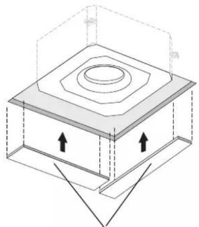
natural_image
Isometric diagram of a mechanical or architectural component with concentric layers and directional arrows, no text or symbols present.b
natural_image
Isometric line drawing of concentric and nested geometric shapes (no text or symbols)b
text_image
Technical diagram showing mechanical assembly with labeled parts and a close-up of a component being inserted into a housing.text_image
1~1.5 m atext_image
≥100 a A (mm)a T-Verbindung
natural_image
Technical line drawing of a mechanical assembly with mounting brackets and a central circular component (no text or symbols)a Ablaufstutzen
natural_image
Technical diagram of an air conditioning unit with internal components and close-up insets (no text or labels)text_image
Technical diagram showing assembly of mechanical parts with labeled components a, b, and c3-Wege EIN/AUS Ventil-Kit
text_image
Technical diagram showing assembly of mechanical components with labeled parts a and b, including a magnified inset view.text_image
Technical diagram showing installation of a mechanical component with labeled parts and directional arrows indicating motion or assembly.text_image
Technical diagram showing mechanical assembly with labeled parts (e, m) and numbered components3-Wege EIN/AUS Ventil-Kit
text_image
Technical diagram showing mechanical assembly with labeled components and exploded views6 Elektroinstallation
natural_image
Technical line drawing of a mechanical assembly with four circular components and mounting holes (no text or symbols)natural_image
Technical line drawing of an electrical enclosure with internal components and wiring (no text or labels)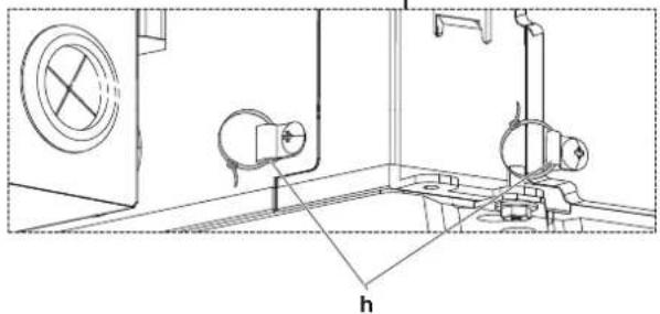
natural_image
Technical line drawing of a mechanical assembly with labeled component 'h' (no text or symbols beyond label)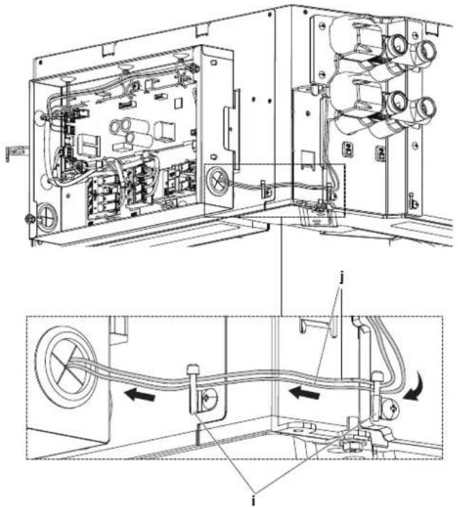
natural_image
Technical line drawing of an electrical enclosure with internal components and wiring, showing internal wiring connections (no text or labels)GEFAHR: STROMSCHLAGGEFAHR

WARNUNG
GEFAHR: STROMSCHLAGGEFAHR

WARNUNG
GEFAHR: STROMSCHLAGGEFAHR
GEFAHR: STROMSCHLAGGEFAHR

WARNUNG
natural_image
Technical line drawing of a mechanical device with a magnified inset showing a circular component (no text or symbols)text_image
Technical diagram of an electronic device showing internal components and wiring, labeled with parts a and b.natural_image
Technical line drawing of an internal electronic device with exposed circuitry and wiring (no text or labels)natural_image
Technical line drawing of an internal electronic device casing with visible wiring and components (no text or labels)natural_image
Technical line drawing of an internal electronic device with exposed wiring and components (no text or labels)6 Kabelschelle (c).
natural_image
Technical diagram of an electronic device internal structure with wiring and connectors (no text or labels)7
natural_image
Technical line drawing of a mechanical or electrical enclosure with no visible text, numbers, or symbols.7 Konfiguration
GEFAHR: STROMSCHLAGGEFAHR
GEFAHR: STROMSCHLAGGEFAHR

HINWEIS
text_image
Illustration showing hands using a clipboard to write documents on a tablet, with a magnified view of the document being inserted.Zierblende:
natural_image
Diagram of hands installing a grid-patterned device on a substrate (no text or symbols visible)text_image
Diagram illustrating a mechanical assembly with numbered components and directional arrows indicating motion or assembly steps.Zierblende:
text_image
Technical diagram showing a grid device with numbered components and directional arrows indicating assembly or installation steps.natural_image
Technical line drawing of a portable air purifier connected to a flatboard with a cable, alongside a separate flatboard with wiring (no text or symbols)text_image
Exploded view diagram of a mechanical device with numbered components for identification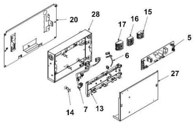
text_image
Exploded view diagram of an electronic device with numbered components for identificationflowchart
graph TD
    subgraph Indoor
        L --> Q1R
        N --> Q2U
        Q1R --> F2U
        F2U --> X1M
        X1M --> BRN
        BRN --> BLU
        BLU --> BLK
        BLK --> GRN-YLW
        GRN-YLW --> X35A
        X35A --> X32A
        X32A --> X37A
    end

    subgraph Electronic_Control_FWECSAC(OPTION)
        A3P --> H3P
        H3P --> X4A
        X4A --> C1
        C1 --> N
        N --> L
        L --> X3A
    end

    subgraph Electronic_Board_FWECSAP(OPTION)(NOTE 3)
        A2P --> X4A
        A2P --> X1A
        A2P --> CA
        X36A --> X8A
        X8A --> X10A
    end

    subgraph Decoration Panel_BYF0600(OPTION)(NOTE 2)
        A4P --> X7A
        A4P --> X6A
        A4P --> X5A
        A4P --> X3M
        A4P --> X24A
        A4P --> RIT
    end

    subgraph Advanced_Plus_Remote_Controller_FWE03A(OPTION)(NOTE 3)
        A2P --> X2A
        A2P --> X1A
        A2P --> CA
        X36A --> X8A
        X8A --> X9A
        X9A --> X10A
        X10A --> MSX
        X10A --> MSW
        X10A --> MSN
        X10A --> MSU
        X10A --> MSV
        X10A --> MSW
        X10A --> MSN
        X10A --> MSU
        X10A --> MSV
        X10A --> MSW
        X10A --> MSN
        X10A --> MSU
    end

    subgraph_Control_Layer_Board["Indoor"]
        Z2C --> GRN
        Z2C --> VIR
        VIR --> AIP_C305
        PS --> BLU_RED
        BLU_RED --> X20A
        X20A --> WHT_ORG_BLU
        WHT_ORG_BLU --> Z1C
    end

    subgraph_Control_Say_Board["Control_Say"]
        H1P --> DS1_ON_OFF
        DS1_ON_OFF --> X50_ON_OFF
        X50_ON_OFF --> YLRW_BRN
        YLRW_BRN --> BSW_MIS_MIS_MIS_MIS_MIS_MIS_MIS_MIS_MIS_MIS_MIS_MIS_MIS_MIS_MIS_MIS_MIS_MIS_MIS_MIS_MIS_MIS_MIS_MIS_MIS_MIS_MIS_MIS_MIS_MIS_MIS_MIS_MIS_MIS_MIS_MIS_MIS_MIS_MIS_MIS_MIS_MIS_MIS_MIS_MIS_MIS_MIS_MIS_MIS_MIS_Mis_MIS_MIS_MIS_MIS_MIS_MIS_MIS_MIS_MIS_MIS_MIS_MIS_MIS_MIS_MIS_MIS_MIS_MIS_MIS_MIS_MIS_MIS_MIS_MIS_MIS_MIS_MIS_MIS_MIS_MIS_MIS_MIS_MIS_MIS_MIS_MIS_MIS_MIS_MIS_Mis_MiMMS_VIR_C305_C305_C305_C305_C305_C305_C305_C305_C305_C305_C305_C305_C305_C305_C305_C305_C305_C305_C305_C305_C305_C305_C305_C305_C305_C30 |
    subgraph_Control_Layer_Board["Control_Layer"]
        H1P --> DS1_ON_OFF
        DS1_ON_OFF --> YLRW_BRN
        YLRW_BRN --> BSW_MiMMS_VIR_C305_C305_C305_C305_C305_C305_C305_C305_C305_C305_C305_C305_C305_C305_C305_C305_C305_C305_C305_C305_C305_C305_C305_CmI_PL_OM_OM_OM_OM_OM_OM_OM_OM_OM_OM_OM_OM_OM_OM_OM_OM_OM_OM_OM_OM_OM_OM_OM_OM_OM_OM_OM_OM_OM_OM_OM_OM_OM_OM_OM_OM_OM_OM_OM_OM_OM_OM_OM_OM_OM_OM_OM_OM_OM_OM_OPDBLU/LBK
    end

    subgraph_Control_Layer_Pack["Control_Layer"]
        H1P --> DS1_ON_OFF
        DS1_ON_OFF --> YLRW_BRN
        YLRW_BRN --> BSW_MiMMS_VIR_C305_C305_C305_C305_C305_C305_C305_C305_C305_C305_C305_C305_C305_C305_CmI_PL_OM_OM_OM_OM_OM_OM_OM_OM_OM_OM_OM_OM_OM_OM_OM_OM_OM_OM_OM 1_X24A 4_X24A 4_X24A 4_X24A 4_X24A 4_X24A 4_X24A 4_X24A 4_X24A 4_X24A 4_X24A 4_X24A 4_X24A 4_X24A 4_X24A 4_X24A 4_X24A 4_X24B MIP MIP MIP MIP MIP MIP MIP MIP MIP MIP MIP MIP MIP MIP MIP MIP MIP MIP MIP MIP MIP MIP MIP MIP MIP MIP MIP MIP MIP MIP MIP MIP MIP MIP MIP MIP MIP MIP MIP MIP MIP MIP MIP MIP MIP MIP MIP MIP MIP MIP MIF MIF MIF MIF MIF MIF MIF MIF MIF MIF MIF MIF MIF MIF MIF MIF MIF MIF MIF MIF MIF MIF MIF MIF MIF MIF MIF MIF MIF MIF MIF MIF MIF MIF MIF MIF MIF MIF MIF MIF MIF MIF MIF MIF MIF MIF MIF MIF MIF MIF Mif PLSMMSMMSMMSMMSMMSMMSMMSMMSMMSMMSMMSMMSMMSMMSMMSMMSMMSMMSMMSMMSMMSMMSMMSMMSMMSMMSMMSMMSMMSMMSMMSMMSMMSMMSMMSMMSMMSMMSMMSMMSMMSMMSMMSMMSMMSMMSMMSMMSMMSMMSMMLSMLSMLSMLSMLSMLSMLSMLSMLSMLSMLSMLSMLSMLSMLSMLSMLSMLSMLSMLSMLSMLSMLSMLSMLSMLSMLSMLSMLSMLSMLSMLSMLSMLSMLSMLSMLSMLSMLSMLSMLSMLSMLSMLSMLSMLSMLSMLSMLSMLSMLTSLTSLTSLTSLTSLTSLTSLTSLTSLTSLTSLTSLTSLTSLTSLTSLTSLTSLTSLTSLTSLTSLTSLTSLTSLTSLTSLTSLTSLTSLTSLTSLTSLTSLTSLTSLTSLTSLTSLTSLTSLTSLTSLTSLTSLTSLTSLTSLTSLTSLTTLTTLTTLTTLTTLTTLTTLTTLTTLTTLTTLTTLTTLTTLTTLTTLTTLTTLTTLTTLTTLTTLTTLTTLTTLTTLTTLTTLTTLTTLTTLTTLTTLTTLTTLTTLTTLTTLTTLTTLTTLTTLTTLTTLTTLTTLTTLTTLTTLTTLTLLTTLLTTLLTTLLTTLLTTLLTTLLTTLLTTLLTTLLTTLLTTLLTTLLTTLLTTLLTTLLTTLLTTLLTTLLTTLLTTLLTTLLTTLLTTLLTTLLTTLLTTLLTTLLTTLLTTLLTTLLTTLLTTLLTTLLTTLLTTLLTTLLTTLLTTLLTTLLTTLLTTLLTTLLTTLLTTLLTTLLTTLLTTLLTTLLTTLLTTLLTCSSMAHSSMAHSSMAHSSMAHSSMAHSSMAHSSMAHSSMAHSSMAHSSMAHSSMAHSSMAHSSMAHSSMAHSSMAHSSMAHSSMAHSSMAHSSMAHSSMAHSSMAHSSMAHSSMAHSSMAHSSMAHSSMAHSSMAHSSMAHSSMAHSSMAHSSMAHSSMAHSSMAHSSMAHCCCTCTCTCTCTCTCTCTCTCTCTCTCTCTCTCTCTCTCTCTCTCTCTCTCTCTCTCTCTCTCTCTCTCTCTCTCTCTCTCTCTCTCTCTCTCTCTCTCTCTCTCTCTCTCTCTCTCTCTCTCTCTCTCTCTCTCTCTCTCTCTCTCTCTCTCTCTCTCTCTCTCTCTCTCTCTCTCTACTATCKSTCKSTCKSTCKSTCKSTCKSTCKSTCKSTCKSTCKSTCKSTCKSTCKSTCKSTCKSTCKSTCKSTCKSTCKSTCKSTCKSTCKSTCKSTCKSTCKSTCKSTCKSTCKSTCKSTCKSTCKSTCKSTCKSTCKSTCKSTCKSTCKSTCKSTCKSTCKSTCKSTCKSTCKSTCKSTCKSTCKSTCKSTCKSTCKSTCKSTCK STCKSTCK STCK STCK STCK STCK STCK STCK STCK STCK STCK STCK STCK STCK STCK STCK STCK STCK STCK STCK STCK STCK STCK STCK STCK STCK STCK STCK STCK STCK STCK STCK STCK STCK STCK STCK STCK STCK STCK STCK STCK STCK STCK STCK STCK STCK STCK STCK STCK STCK STCK STCK TCR SSW SA SA SU BIVFQ6XXO (OPTION) (NOTE 2)
    end
Hinweise:
natural_image
Technical line drawing of a mechanical housing or enclosure with internal components and mounting brackets (no text or symbols)14.4 After a long stop period 71
14.5 Before a long stop period 72
The original instructions are written in English. All other languages are translations of the original instructions.
Données techniques
natural_image
Technical line drawing of a mechanical assembly with multiple hands operating it (no text or symbols present)
REMARQUE
text_image
Technical diagram showing a hand operating a device with labeled components and a cross symbol indicating failure or invalid status.natural_image
Technical line drawing of a mechanical housing or enclosure with mounting brackets and internal components (no text or symbols)text_image
Diagram showing a hand using a drill to install a component on a grid, with labeled components and directional arrows.text_image
a b c d e Atext_image
Diagram showing a geometric setup with labeled components (a, b, c, d) and an inset of a triangle with a horizontal line.text_image
Technical diagram showing mechanical assembly with labeled parts and a close-up of a component being inserted into a housing.natural_image
Technical line drawing of a mechanical assembly with mounting brackets and a central circular component (no text or symbols)a Raccord de purge
natural_image
Technical diagram of an air conditioning unit with internal components and two close-up views (a and b), no visible text or symbols.text_image
Technical diagram showing mechanical assembly with labeled parts a, b, and c, including directional arrows and component arrangements.text_image
Technical diagram showing mechanical assembly with labeled component 'd' and directional arrows indicating motion or flowtext_image
Technical diagram showing assembly of mechanical components with labeled parts a and b, including a magnified inset of a tool.2 Actionneurs (d)
natural_image
Technical line drawing of a mechanical assembly with mounting brackets and a labeled component 'e' (no text or symbols beyond label)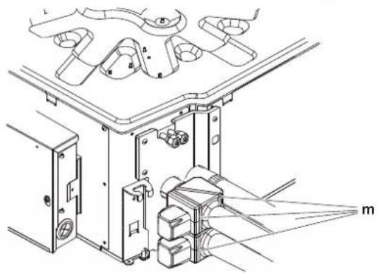
natural_image
Technical line drawing of a mechanical assembly with no visible text or symbolstext_image
Technical diagram of a mechanical assembly with labeled components and directional arrowsnatural_image
Technical line drawing of an automotive engine assembly with no visible text or symbolsnatural_image
Technical line drawing of a mechanical assembly with four circular components and mounting holes (no text or symbols)natural_image
Technical line drawing of an electrical enclosure with internal components and a close-up view of the interior (no text or symbols)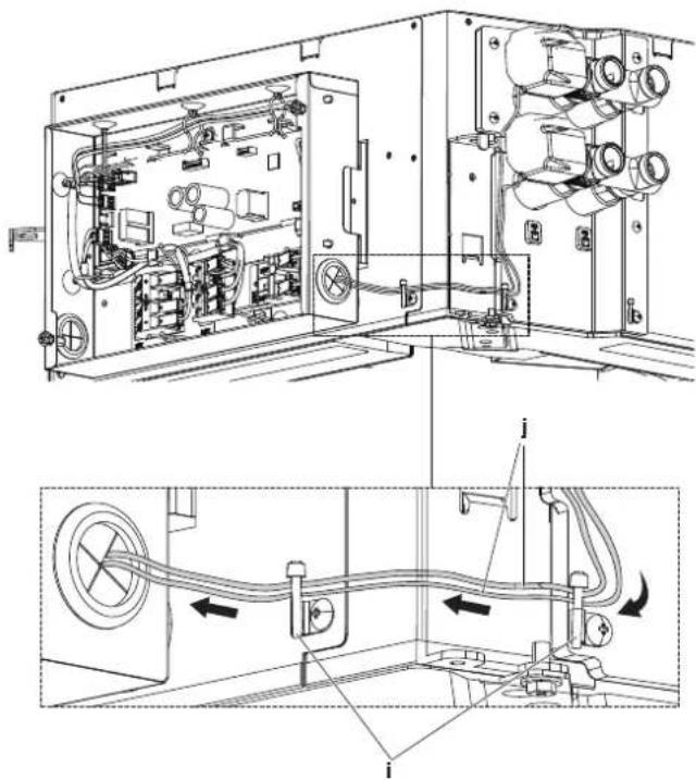
natural_image
Technical line drawing of an electrical enclosure with internal components and wiring, showing internal wiring and connection points (no text or symbols)natural_image
Technical line drawing of a mechanical device with a magnified inset showing a circular component detail (no text or symbols)natural_image
Technical diagram of an electronic device interior showing internal components and wiring (no text or labels)natural_image
Technical line drawing of an internal electronic device with exposed wiring and ports (no text or symbols)natural_image
Technical line drawing of an internal electronic device with exposed wiring and components (no text or symbols)natural_image
Technical line drawing of an internal electronic device with exposed wiring and components (no text or labels)6 Serre-câbles (c).

natural_image
Interior view of an electronic device showing internal components and wiring (no text or symbols visible)7
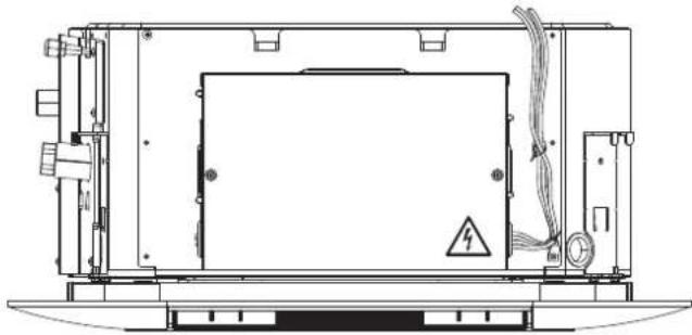
natural_image
Technical line drawing of an electrical enclosure or enclosure with warning symbol and wiring (no text or labels)7 Configuration
natural_image
Technical line drawing of an electronic device interior showing internal components and wiring (no text or labels)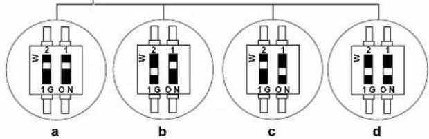
text_image
2 1 W 2 1 1G O N a b W 2 1 1G O N c W 2 1 1G O N d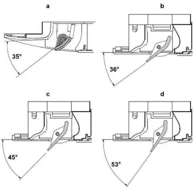
8 Mise en service

REMARQUE
natural_image
Illustration of hands using a tool to write or edit documents on a laptop (no text or symbols present)Panneau design:
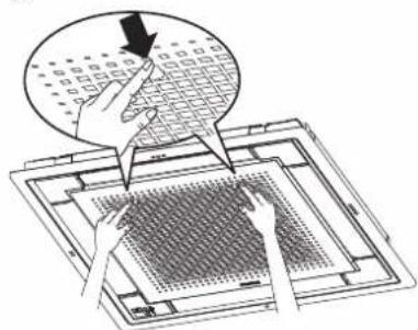
text_image
Diagram showing hands installing a grid-based device with a magnified view of the grid pattern and a downward arrow indicating action.text_image
Diagram illustrating airflow or ventilation system with numbered components and directional arrows indicating movementPanneau design:
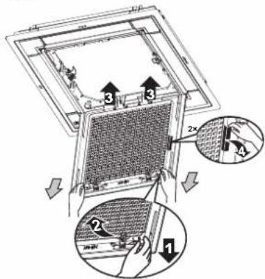
text_image
Diagram illustrating a window grating mechanism with numbered steps and magnified views of the process.natural_image
Technical line drawing of a portable solar panel with a coiled cable and a flat panel, no text or symbols present.14.4 After a long stop period
E.g., at the beginning of the season.
E.g., at the end of the season.
If one of the following malfunctions occur, take the measures shown below and contact your dealer.
The system MUST be repaired by a qualified service person.
text_image
Exploded view diagram of a mechanical device with numbered components for identificationtext_image
Exploded view diagram of an electronic device with numbered components for identificationflowchart
graph TD
    subgraph Indoor
        L --> QIR
        N --> QIR
        QIR --> F2U
        F2U --> ControlPanel
        ControlPanel --> X1M
        ControlPanel --> X3A
        ControlPanel --> X4A
        ControlPanel --> X5A
        ControlPanel --> X6A
        ControlPanel --> X7A
        ControlPanel --> X8A
        ControlPanel --> X9A
        ControlPanel --> X10A
        ControlPanel --> X11A
        ControlPanel --> X12A
        ControlPanel --> X13A
        ControlPanel --> X14A
        ControlPanel --> X15A
        ControlPanel --> X16A
        ControlPanel --> X17A
        ControlPanel --> X18A
        ControlPanel --> X19A
        ControlPanel --> X20A
        ControlPanel --> X21A
        ControlPanel --> X22A
        ControlPanel --> X23A
        ControlPanel --> X24A
        ControlPanel --> X25A
        ControlPanel --> X26A
        ControlPanel --> X27A
        ControlPanel --> X28A
        ControlPanel --> X29A
        ControlPanel --> X30A
        ControlPanel --> X31A
        ControlPanel --> X32A
        ControlPanel --> X33A
        ControlPanel --> X34A
        ControlPanel --> X35A
        ControlPanel --> X36A
    end

    subgraph Outdoor
        L --> BRN
        N --> BLU
        N --> BLK
        N --> GRN-YLW
    end

    subgraph Electronic_Control_FWECSAC_OPTION
        A3P --> H3P
        H3P --> X4A
        X4A --> C1
        C1 --> N
        N --> T
        T --> H1P_H2P
    end

    subgraph Electronic_BOARD_FWECSAP_OPTION (NOTE 3)
        A2P --> X4A
        A2P --> X2A
        A2P --> X1A
        A2P --> CA
    end

    subgraph Decoration Panel_BYFQ00C_OPTION (NOTE 2)
        A5P --> X8A
        A5P --> X9A
        A5P --> X10A
        A5P --> MSV
        A5P --> MSN
        A5P --> MSW
        A5P --> MSX
    end

    subgraph Advanced_Plus_Remote_Controller_FWE3A_OPTION (NOTE 3)
        A4P --> X7A
        A4P --> X6A
        A4P --> X5A
        A4P --> SKSIVSA_SA_SU_BU
        A4P --> R1T
    end

    subgraph_Power_Supply["Power Supply"]
        X1M --> BLK_BLU_RED["BLK"]
        N --> L["Power Supply"]
        X3M --> O-IOV["0-10V"]
        COM --> COM["COM"]
    end

    subgraph_Smart_Traffic["Smart"]
    M1F["MS"] --> Z1C
    Z1C --> WHT_ORG["ORG"]
    Z1C --> BLU_BLU_BLU_BLU_BLU_BLU_BLU_BLU_BLU_BLU_BLU_BLU_BLU_BLU_BLU_BLU_BLU_BLU_BLU_BLU_BLU_BLU_BLU_BLU_BLU_BLU_BLU_BLU_BLU_BLU_BLU_BLU_BLU_BLU_BLU_BLU_BLU_BLU_BLU_BLU_BLU_BLU_BLU_BLU_BLU_BLU_BLU_BLU_BLU_BLU_BLU Jeans 20000000000000000000000000000000000000000000000000000000000000000000000000000000000000000000000000000

    subgraph_Smart_Traffic["Red,WHT"]
    M1P --> BS1_5["BS1"]
    BS1_5 --> BLK_4["BLK"]
    BLK_4 --> BLK_4BLK["BLK"]
    BLK_4BLK["BLK"]
    BLK_4BLK["BLK"]
    BLK_4BLK["BLK"]
    BLK_4BLK["BLK"]
    BLK_4BLK["BLK"]
    BLK_4BLK["BLK"]
    BLK_4BLK["BLK"]
    BLK_4BLK["BLK"]
    BLK_4BLK["BLK"]
    BS1_5 --> BS2_5a["BS2"]
    BS2_5a --> BS2_5b["BS2"]
    BS2_5b --> BS2_5c["BS2"]
    BS2_5c --> BS2_5d["BS2"]
    BS2_5d --> BS2_5e["BS2"]
    BS2_5e --> BS2_5f["BS2"]
    BS2_5f --> BS2_5g["BS2"]
    BS2_5g --> BS2_5h["BS2"]
    BS2_5h --> BS2_5i["BS2"]
    BS2_5i --> BS2_5j["BS2"]
    BS2_5j --> BS2_5k["BS2"]
    BS2_5k --> BS2_5l["BS2"]
    BS2_5l --> BS2_5m["BS2"]
    BS2_5m --> BS2_5n["BS2"]
    BS2_5n --> BS2_5o["BS2"]
    BS2_5o --> BS2_5p["BS2"]
    BS2_5p --> BS2_5q["BS2"]
    BS2_5q --> BS2_5r["BS2"]
    BS2_5r --> BS2_5s["BS2"]
    BS2_5s --> BS2_5t["BS2"]

    subgraph_Smart_Traffic["Red,WHT"]
    M1P --> BS1_5a["BS1"]
    BS1_5a --> BS1_5b["BS1"]
    BS1_5b --> BS1_5c["BS1"]
    BS1_5c --> BS1_5d["BS1"]
    BS1_5d --> BS1_5e["BS1"]
    BS1_5e --> BS1_5f["BS1"]
    BS1_5f --> BS1_5g["BS1"]
    BS1_5g --> BS1_5h["BS1"]
    BS1_5h --> BS1_5i["BS1"]
    BS1_5i --> BS1_5j["BS1"]
    BS1_5j --> BS1_5k["BS1"]
    BS1_5k --> BS1_5l["BS1"]
    BS1_5l --> BS1_5m["BS1"]
    BS1_5m --> BS1_5n["BS1"]
    BS1_5n --> BS1_5o["BS1"]
    BS1_5o --> BS1_5p["BS1"]
    BS1_5p --> BS1_5q["BS1"]
    BS1_5q --> BS1_5r["BS1"]
    BS1_5r --> BS1_5s["BS1"]
    BS1_5s --> BS1_5t["BS1"]

    subgraph_Smart_Traffic["POL"]
    HIP --> DS1_ON_OFF["HIP"]
    DS1_ON_OFF["HIP"] --> ON_OFF_ON_OFF["ON"]
    ON_OFF_ON_OFF["HIP"] --> OFF_ON_OFF["HIP"] --> OFF_ON_OFF["HIP"] --> OFF_ON_OFF["HIP"] --> OFF_ON_OFF["HIP"] --> OFF_ON_OFF["HIP"] --> OFF_ON_OFF["HIP"] --> OFF_ON_OFF["HIP"] --> OFF_ON_OFF["HIP"] --> OFF_ON_OFF["HIP"] --> OFF_ON_OFF["HIP"] --> OFF_ON_OFF["HIP"] --> OFF_ON_OFF["HIP"] --> OFF_ON_OFF["HIP"] --> OFF_ON_OFF["HIP"] --> OFF_ONward
    end

    subgraph Smart_Traffic_POL_POL_POL_POL_POL_POL_POL_POL_POL_POL_POL_POL_POL_POL_POL_POL_POL_POL_POL_POL_POL_POL_POL_POL_POL_POL_POL_POL_POL_POL_POL_POL_POL_POL_POL_POL_POL_POL_POL_POL_POL_POL_POL_POL_POL_POL_POL_POL_POL_POL_POLL_POLL_POLL_POLL_POLL_POLL_POLL_POLL_POLL_POLL_POLL_POLL_POLL_POLL_POLL_POLL_POLL_POLL_POLL_POLL_POLL_POLL_POLL_POLL_POLL_POLL_POLL_POLL_POLL_POLL_POLL_POLL_POLL_POLL_POLL_POLL_POLL_POLL_POLL_POLL_POLL_POLL_POLL_POLL_POLL_POLL_POLL_POLL_POLL_POLL_Poll_Poll_Poll_Poll_Poll_Poll_Poll_Poll_Poll_Poll_Poll_Poll_Poll_Poll_Poll_Poll_Poll_Poll_Poll_Poll_Poll_Poll_Poll_Poll_Poll_Poll_Poll_Poll_Poll_Poll_Poll_Poll_Poll_Poll_Poll_Poll_Poll_Poll_Poll_Poll_Poll_Poll_Poll_Poll_Poll_Poll_Poll_Poll_Poll_Poll_RIT_t^T ADVANCED_PLUS_REMOTE_CONTROLLER_FWE3A_OPTION(NOTE 3)
    end
Remarques:
natural_image
Technical line drawing of a mechanical housing or enclosure with internal components and mounting brackets (no text or symbols)natural_image
Technical line drawing of a mechanical assembly with multiple hands operating it (no text or symbols present)
OPMERKING
text_image
Technical diagram showing a hand operating a device with labeled components and a cross symbol indicating failure or disassembly.natural_image
Technical line drawing of a mechanical housing or enclosure with mounting brackets and a central circular component (no text or symbols)Modelidentificatie
text_image
Diagram showing a hand using a drill to install a component, with labeled parts and directional arrows indicating movement or assembly.text_image
Technical diagram showing a structural component with labeled parts a, b, c, d and an inset view of a triangular element.text_image
Technical diagram illustrating a multi-step assembly or installation process with labeled components and directional arrows indicating movement.text_image
Technical diagram showing mechanical assembly with labeled parts and a close-up of a component being inserted into a housing.text_image
1~1.5 m anatural_image
Technical line drawing of a mechanical assembly with no visible text or symbolsa Afvoeraansluiting
natural_image
Technical line drawing of an air conditioning unit with internal components and two circular insets showing internal wiring (no text or labels)a Siliconenslang (accessoireset sierpaneel)
b Kabelbinder (accessoireset sierpaneel)
AAN/UIT-kleppenkits installeren

OPMERKING
text_image
Technical diagram showing assembly of mechanical components with labeled parts a, b, and ctext_image
Technical diagram showing assembly of mechanical components with labeled parts a and b, including a magnified inset of a tool.2 Motoren (d)
text_image
Technical diagram showing mechanical assembly with labeled component 'd' and directional arrows indicating motion or flow3 Klepisolatie (e) en kabelbinders (m)
text_image
Technical diagram showing mechanical assembly with labeled parts and exploded views, including components e and m.text_image
Technical diagram of a mechanical assembly with labeled components and directional arrows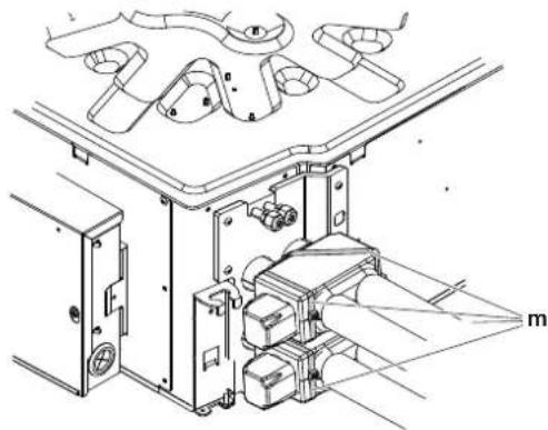
natural_image
Technical line drawing of a mechanical assembly with mounting brackets and internal components (no text or symbols)natural_image
Technical line drawing of an electrical enclosure with internal components and a close-up view of the interior (no text or symbols)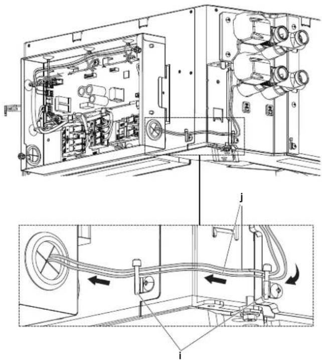
text_image
Technical diagram of an electrical enclosure with labeled components and wiring, showing internal wiring and component layout.natural_image
Technical line drawing of a mechanical device with a magnified inset showing a component detail (no text or symbols)text_image
Technical diagram of an electronic device showing internal components and wiring, labeled with parts a and b.natural_image
Technical line drawing of an internal electronic device with exposed wiring and ports (no text or labels)natural_image
Technical line drawing of an internal electronic device with exposed wiring and components (no text or symbols)natural_image
Technical line drawing of an electrical enclosure with internal components and wiring (no text or symbols)6 Kabelklemmen (c).
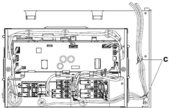
natural_image
Technical line drawing of an internal electronic device with visible wiring and components (no text or symbols)7
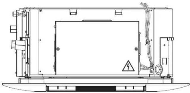
natural_image
Technical line drawing of an electrical enclosure with warning symbol and grounding device (no text or labels)7 Configuratie
7 Configuratie
7.1 Instelling sierpaneel
natural_image
Technical line drawing of an electronic device interior showing internal components like connectors, switches, and wiring (no text or labels)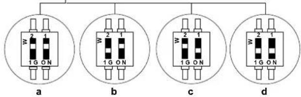
text_image
W 2 1 1 G O N a W 2 1 1 G O N b W 2 1 1 G O N c W 2 1 1 G O N da
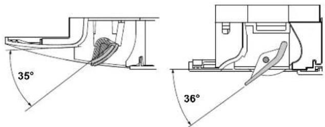
text_image
35° 36°C
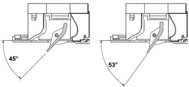
text_image
45° 53°b
8 Inbedrijfstelling

OPMERKING
text_image
Illustration showing hands using a clipboard to write documents on a tablet, with a magnified view of the document being placed over it.Design paneel:
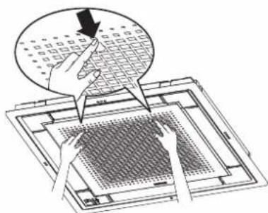
natural_image
Illustration of hands installing a grid-patterned circuit board on an electronic device (no text or symbols visible)text_image
Diagram illustrating airflow or ventilation system with numbered components and directional arrows indicating movementDesign paneel:
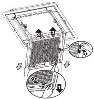
text_image
Diagram illustrating a device's internal structure with numbered components and magnified views of the component.natural_image
Technical line drawing of a vacuum cleaner connected to a grid-mounted device and a separate flat panel with wires (no text or symbols)text_image
Exploded view diagram of a device with numbered components for identificationnatural_image
Technical line drawing of a mechanical housing or enclosure with internal components and mounting brackets (no text or symbols)natural_image
Technical line drawing of a mechanical device with multiple arms and housing (no text or symbols)
AVISO
text_image
Technical diagram showing a hand operating a device with labeled components and a cross symbol indicating failure or disassembly.natural_image
Technical line drawing of a mechanical housing or enclosure with mounting brackets and internal components (no text or symbols)text_image
Diagram showing a hand using a drill to install a panel, with labeled components and directional arrows indicating movement or assembly.text_image
Technical diagram showing a structural component with labeled parts (a, b, c, d) and an inset view of a triangular element.natural_image
Technical line drawing of a mechanical or electrical enclosure with labeled components (a, b), no readable text or symbols present.text_image
Technical diagram illustrating a multi-step assembly or installation process with labeled components and directional arrows indicating movement.text_image
Technical diagram showing mechanical assembly with labeled parts and directional arrows indicating movement or assembly stepstext_image
1~1.5 m atext_image
Diagram showing a mechanical or electrical setup with a red 'X' symbol above a horizontal bar and a connected device below.natural_image
Technical line drawing of a mechanical assembly with mounting brackets and internal components (no text or symbols)a Toma de drenaje
natural_image
Technical line drawing of an air conditioning unit with internal components and two inset views (a and b), no text or symbols present.text_image
Technical diagram showing mechanical assembly with labeled parts a, b, and c, including directional arrows and component arrangements.text_image
Technical diagram showing assembly of mechanical components with labeled parts a and b, including a magnified inset of a wrench.2 Actuadores (d)
text_image
Technical diagram showing mechanical assembly with labeled components and directional arrows indicating motion or flowtext_image
Technical diagram showing mechanical assembly with labeled parts and exploded viewstext_image
Technical diagram of a mechanical assembly with labeled components and mounting points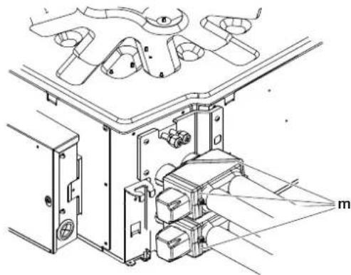
natural_image
Technical line drawing of a mechanical assembly with labeled components (no readable text or symbols)natural_image
Technical line drawing of an electrical enclosure with internal components and a close-up view of the interior (no text or symbols)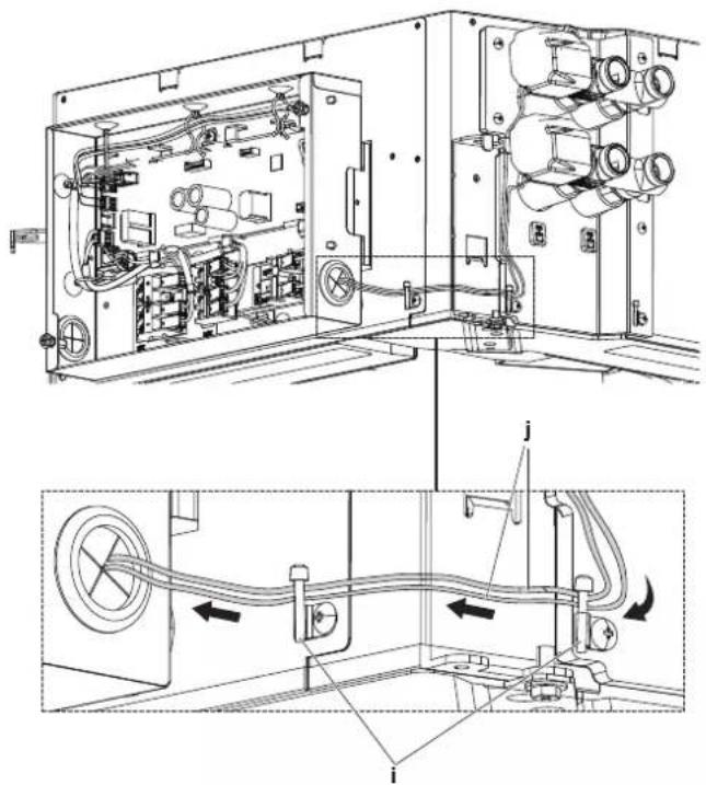
text_image
Technical diagram of an electrical enclosure with labeled components and wiring, showing internal wiring and component layout.natural_image
Technical line drawing of a mechanical device with a magnified inset showing a circular component (no text or symbols)natural_image
Technical diagram of an electronic device showing internal components and wiring (no text or labels)natural_image
Technical line drawing of an electronic device interior showing internal components and wiring (no text or labels)natural_image
Technical line drawing of an internal electronic device casing with visible wiring and components (no text or symbols)natural_image
Technical line drawing of an internal electronic device casing with visible circuitry and wiring (no text or labels)natural_image
Technical line drawing of an internal electronic device with visible wiring and components (no text or symbols)7
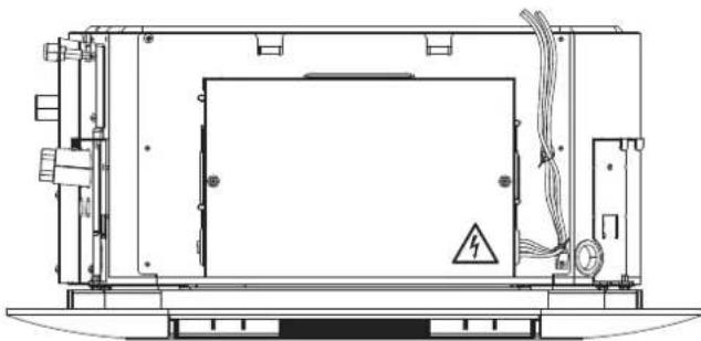
natural_image
Technical line drawing of an electrical enclosure or enclosure with visible wiring and a warning symbol (no text or labels)7 Configuración
7.1 Ajuste del panel decorativo
text_image
Diagram illustrating a hand holding a clipboard with checklist items, showing steps to write on a document or form.Panel de diseño:
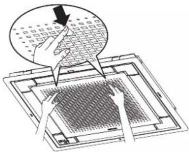
text_image
Diagram showing hands installing a grid-based device with a magnified view of the screen and a cursor pointing to it.2 Retire el filtro de aire.
Panel estándar:
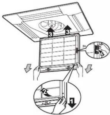
text_image
Diagram illustrating a mechanical assembly with numbered components and directional arrows indicating motion or assembly steps.Panel de diseño:
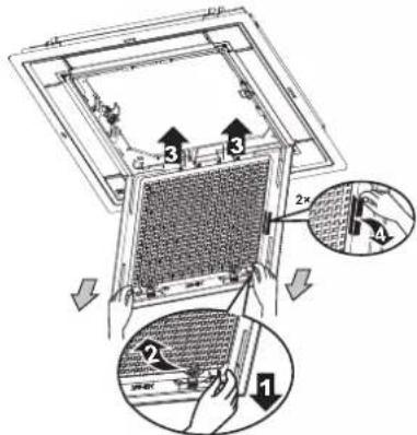
text_image
Diagram illustrating a window grating mechanism with numbered steps and magnified views of the process.natural_image
Illustration of a vacuum cleaner connected to a solar panel and its corresponding electrical socket (no text or symbols present)text_image
Exploded view diagram of a device with numbered components for identification| Materiales | Elemento |
| Componente eléctrico | 1, 2, 3, 4, 5, 6, 7, 8 |
| Aluminio (aleta) + cobre (tubo) + acero galvanizado (placa) + latón + espuma plástica | 9 |
| Plástico | 10, 11, 12, 13, 14, 32 |
| Plástico + metal | 15, 16, 17, 18 |
| Acero galvanizado | 19 ~ 27 |
| Acero galvanizado + plástico | 28 |
| Latón | 31 |
| EPS (espuma de poliestireno expandida) + metal + espuma plástica | 29, 30 |
17 Datos técnicos
natural_image
Technical line drawing of a mechanical housing or enclosure with internal components and mounting brackets (no text or symbols)natural_image
Technical line drawing of a mechanical device with multiple blades and mounting brackets (no text or symbols)
AVVISO
text_image
Technical diagram showing a hand operating a device with labeled components and a cross symbol indicating failure or inspection.natural_image
Technical line drawing of a mechanical housing or enclosure with mounting brackets and internal components (no text or symbols)text_image
Diagram showing a hand using a drill to install a component on a workbench, with labeled parts and directional arrows.text_image
Technical diagram showing a structural element with labeled components (a, b, c, d) and an inset image of a triangular load distribution.text_image
Technical diagram showing mechanical assembly with labeled parts and a zoomed-in detail view of the component.natural_image
Technical line drawing of a mechanical assembly with labeled components (no text or symbols present)natural_image
Technical line drawing of an air conditioning unit with internal components and two close-up insets (a and b), no text or symbols present.text_image
Technical diagram showing mechanical assembly with labeled parts a, b, and c, including directional arrows and component layouts.text_image
Technical diagram showing assembly of mechanical components with labeled parts a and b, including a magnified inset view.2 Attuatori (d)
text_image
Technical diagram showing mechanical assembly with labeled component 'd' and directional arrows indicating motion or movement.text_image
Technical diagram showing mechanical assembly with labeled parts and exploded views, including components e and m.text_image
Technical diagram of a mechanical assembly with labeled components and directional arrows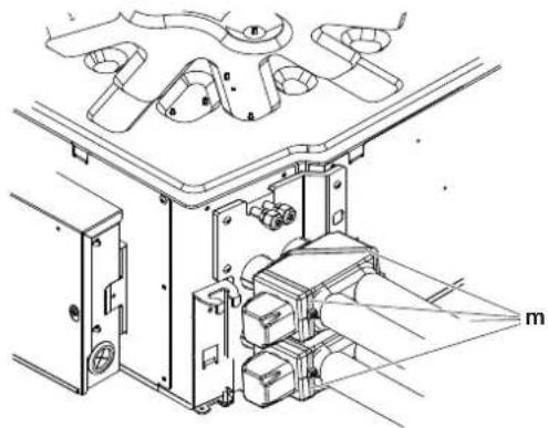
natural_image
Technical line drawing of a mechanical assembly with labeled components (no readable text or symbols)natural_image
Technical line drawing of an electrical enclosure with internal components and a close-up view of the exterior panel (no text or symbols present)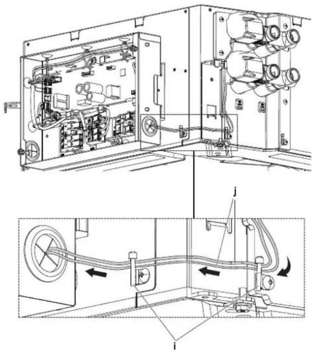
natural_image
Technical line drawing of an electrical enclosure with internal components and wiring, showing assembly and connection details (no text or symbols)natural_image
Technical line drawing of a mechanical device with a magnified inset showing a circular component detail (no text or symbols)natural_image
Interior view of an electronic device showing internal components and wiring (no text or labels visible)natural_image
Technical line drawing of an electronic device interior showing internal components and wiring (no text or labels)natural_image
Technical line drawing of an internal electronic device casing with visible wiring and components (no text or labels)natural_image
Technical line drawing of an internal electronic device casing with visible circuitry and wiring (no text or labels)6 Serracavi (c).
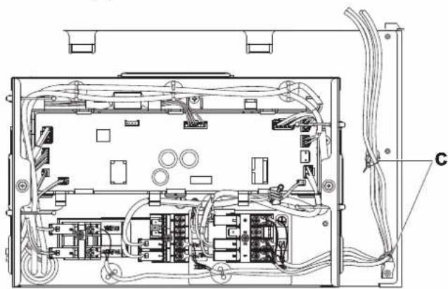
natural_image
Interior view of an electronic device showing internal components and wiring (no text or symbols visible)7
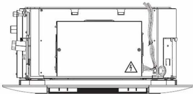
natural_image
Technical line drawing of a mechanical or electrical enclosure with no visible text, numbers, or symbols.7 Configurazione
7 Configurazione
natural_image
Technical line drawing of an electronic device interior showing internal components like connectors, switches, and wiring (no text or labels)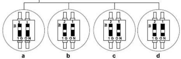
text_image
a b c da
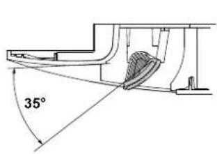
text_image
35°c
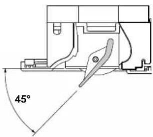
text_image
45°b

text_image
36°d
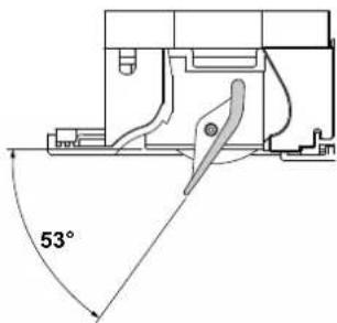
text_image
53°natural_image
Illustration of hands using a tool to write or edit documents on a laptop (no text or symbols visible)Pannello design:
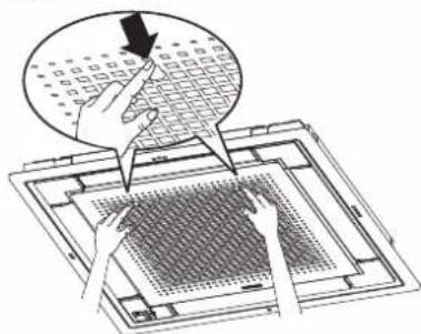
text_image
Diagram showing hands installing a grid-based component with a magnified view highlighting the grid pattern and directional arrow.text_image
Diagram illustrating airflow or ventilation system with numbered components and directional arrows indicating movementPannello design:
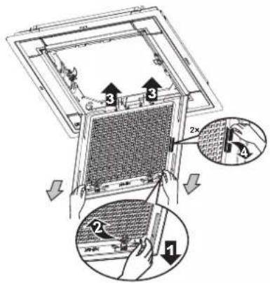
text_image
Diagram illustrating a device's internal structure with numbered components and magnified views of the panel.natural_image
Technical line drawing of a vacuum cleaner and a rectangular electronic component (no text or symbols)text_image
Exploded view diagram of a device with numbered components for identificationnatural_image
Technical line drawing of a mechanical housing or enclosure with internal components and mounting brackets (no text or symbols)Viste laterali con pannello standard (mm)
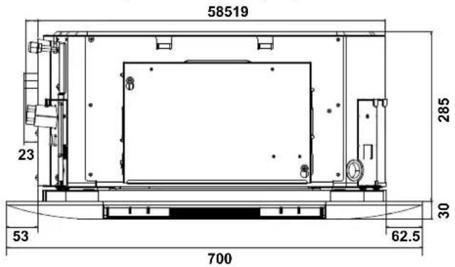
text_image
58519 23 285 30 53 62.5 700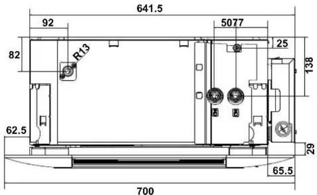
text_image
641.5 92 82 R13 5077 25 138 62.5 29 65.5 700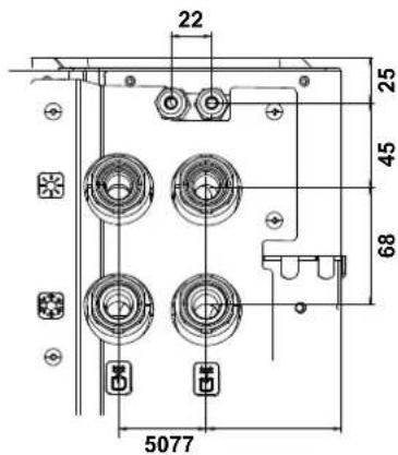
text_image
22 25 45 68 5077Viste laterali con pannello design (mm)
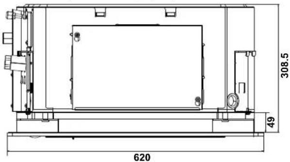
text_image
308.5 49 620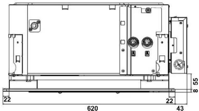
text_image
22 620 22 43 8 55natural_image
Technical line drawing of a mechanical device with multiple blades and housing (no text or symbols)text_image
Technical diagram showing a hand operating a device with labeled components and a cross symbol indicating failure or inspection.natural_image
Technical line drawing of a mechanical housing or enclosure with mounting flanges and internal components (no text or symbols)Στοιχεία μοντέλου
text_image
Diagram showing a hand using a drill to adjust or install a component, with labeled parts and directional arrows.text_image
Technical diagram showing a structural component with labeled parts (a, b, c, d) and an inset image of a triangular load distribution.text_image
Technical diagram showing a square plate with dimension 'a' and a 3D box with concentric rings, plus a hand pointing to the plate.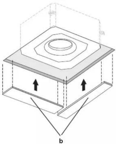
natural_image
Isometric diagram of a mechanical or architectural component with concentric layers and directional arrows, no text or symbols present.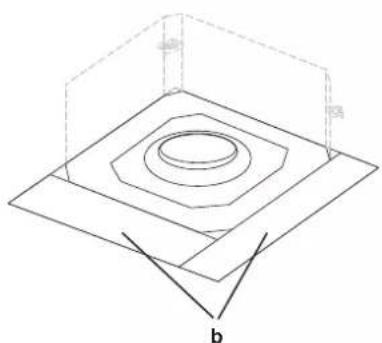
natural_image
Isometric diagram of concentric and nested layers forming a square with a central circular feature, labeled 'b' at the base (no text or symbols within the diagram itself)natural_image
3D mechanical component diagram showing a cylindrical shaft with hexagonal end and central hole, labeled 'c' (no text or symbols beyond label)text_image
Technical diagram showing mechanical assembly with labeled parts and a close-up of a component being inserted into a housing.text_image
1~1.5 m anatural_image
Technical line drawing of a mechanical assembly with mounting brackets and internal components (no text or symbols)natural_image
Technical diagram of an air conditioner unit with internal components and close-up insets (no text or labels)text_image
Technical diagram showing assembly of mechanical parts with labeled components a, b, and ctext_image
Technical diagram showing assembly of mechanical components with labeled parts a and b, including a magnified inset of a mechanical component.2 Ενεργοποιητές (d)
text_image
Technical diagram showing mechanical assembly with labeled component 'd' and directional arrows indicating motion or movement.text_image
Technical diagram of a mechanical assembly with labeled components and mounting bracketsnatural_image
Technical line drawing of a mechanical assembly with labeled components (no readable text or symbols)natural_image
Technical line drawing of a mechanical assembly with mounting brackets and a central housing (no text or symbols)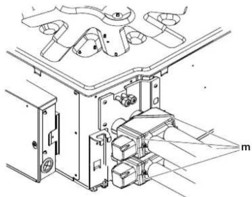
natural_image
Technical line drawing of an electrical enclosure with internal components and wiring (no text or symbols)natural_image
Technical line drawing of a mechanical or electrical component with four circular components and mounting holes (no text or symbols)natural_image
Technical line drawing of an industrial machine with internal components and a close-up view of the interior (no text or symbols)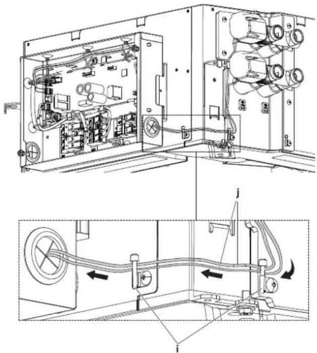
natural_image
Technical line drawing of an internal electrical enclosure with internal components and wiring, showing internal wiring and component layout (no text or labels)natural_image
Technical line drawing of a mechanical device with a magnified inset showing a mechanical component (no text or symbols)natural_image
Technical diagram of an electronic device showing internal components and wiring (no text or labels)natural_image
Interior view of an electronic device showing internal components and wiring (no text or labels visible)natural_image
Technical line drawing of an internal electronic device casing with visible circuitry and wiring (no text or labels)natural_image
Technical line drawing of an electrical enclosure with internal components and wiring (no text or symbols)natural_image
Interior view of an electronic device showing internal components and wiring (no text or symbols visible)7
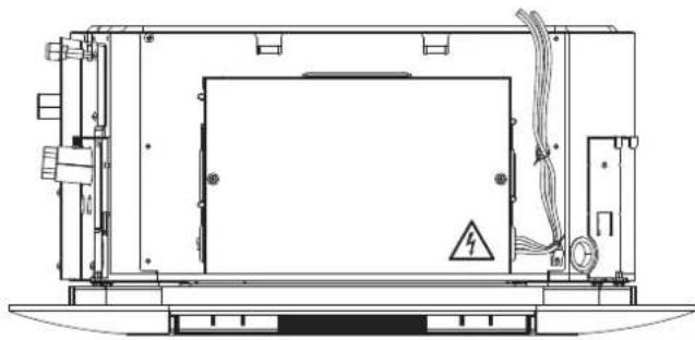
natural_image
Technical line drawing of an electrical enclosure with warning symbol and circuit lines (no text or labels)7 Διαμόρφωση
7 Διαμόρφωση
natural_image
Technical line drawing of an electronic device rear panel with internal components and wiring (no text or labels)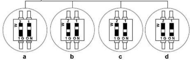
text_image
W 2 1 1G O N a W 2 1 1G O N b W 2 1 1G O N c W 2 1 1G O N da
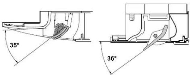
text_image
35° 36°C

text_image
45° 53°b
text_image
Diagram illustrating a document processing step with hand-drawn arrows and labeled sections, showing steps for writing and editing.text_image
Diagram showing hands installing a grid pattern on a microchip, with a magnified view highlighting the grid structure.text_image
Diagram illustrating a window expansion mechanism with numbered components and directional arrows indicating movement or assembly.text_image
Diagram illustrating a window grating mechanism with numbered steps and magnified views of the process.natural_image
Illustration of a vacuum cleaner connected to a solar panel and its corresponding circuit board (no text or symbols present)text_image
Exploded view diagram of a mechanical assembly with numbered components for identification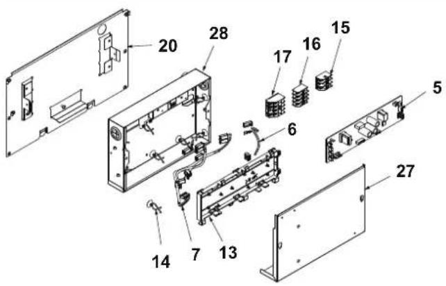
text_image
Exploded view diagram of an electronic device with numbered components for identificationnatural_image
Technical line drawing of a mechanical housing or enclosure with internal components and mounting brackets (no text or symbols)natural_image
Technical line drawing of a mechanical device with multiple blades and housing (no text or symbols)
AVISO
text_image
Technical diagram showing a hand operating a device with labeled components and a cross symbol indicating failure or inspection.natural_image
Technical line drawing of a mechanical housing or enclosure with mounting brackets and internal components (no text or symbols)text_image
Diagram showing a hand using a drill to install a floor panel, with labeled components and directional arrows indicating movement.text_image
Technical diagram showing a structural component with labeled parts a, b, c, d and an inset view of a triangular element.natural_image
Isometric diagram of a mechanical or architectural component with concentric layers and directional arrows, no text or symbols present.b
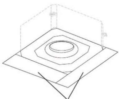
natural_image
Isometric line drawing of concentric and nested geometric shapes (no text or symbols)b
text_image
Technical diagram showing mechanical assembly with labeled parts and a close-up of a component being inserted into a housing.text_image
1~1.5 m atext_image
Diagram showing a mechanical setup with a labeled red 'X' and a horizontal bar, possibly indicating a failure or rejection condition.natural_image
Technical line drawing of a mechanical assembly with labeled components (no text or symbols present)a Encaixe de esgoto
natural_image
Technical diagram of an air conditioning unit with internal components and two close-up views (a and b), no visible text or symbols.text_image
Technical diagram showing mechanical assembly with labeled parts a, b, and c, including directional arrows and component arrangements.Kit de válvulas On-Off de 3 vias
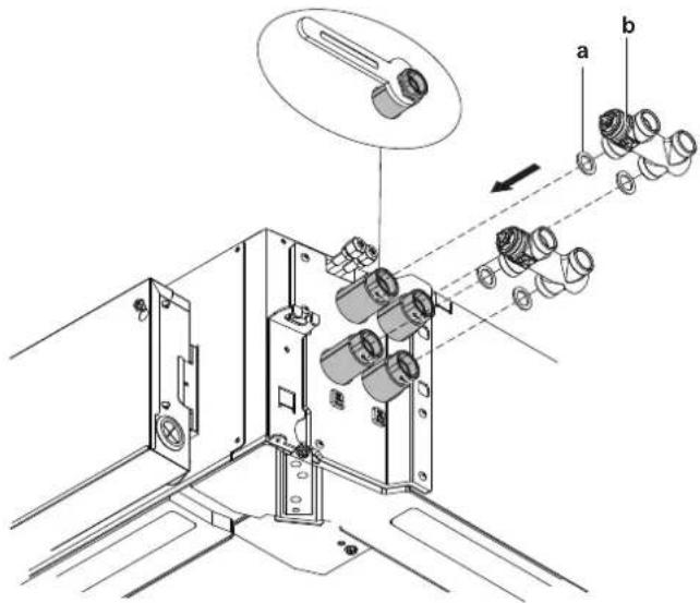
text_image
Technical diagram showing assembly of mechanical components with labeled parts a and b, including a magnified inset of a tool.2 Atuadores (d)
Kit de válvulas On-Off de 2 vias
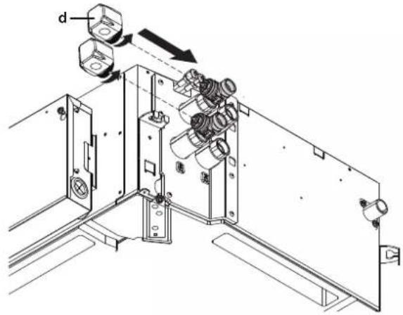
natural_image
Technical line drawing of a mechanical assembly with components and directional arrows (no text or symbols)Kit de válvulas On-Off de 3 vias
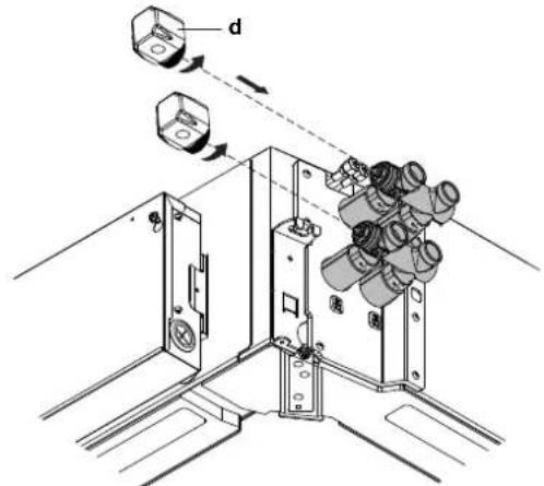
text_image
Technical diagram showing mechanical assembly with labeled component 'd' and directional arrows indicating motion or movement.3 Isolamentos da válvula (e) e braçadeiras (m)
Kit de válvulas On-Off de 2 vias
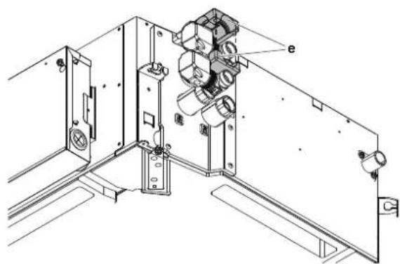
natural_image
Technical line drawing of a mechanical assembly with mounting brackets and a gear mechanism (no text or symbols)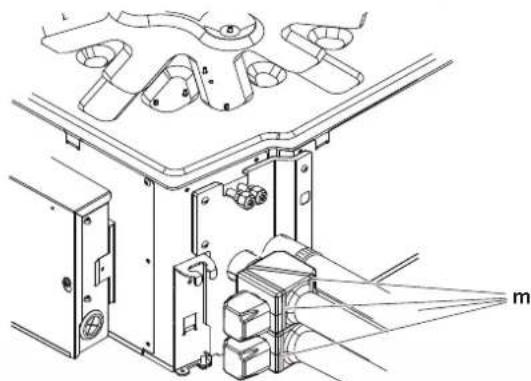
natural_image
Technical line drawing of a mechanical assembly with labeled components (no readable text or symbols)Kit de válvulas On-Off de 3 vias
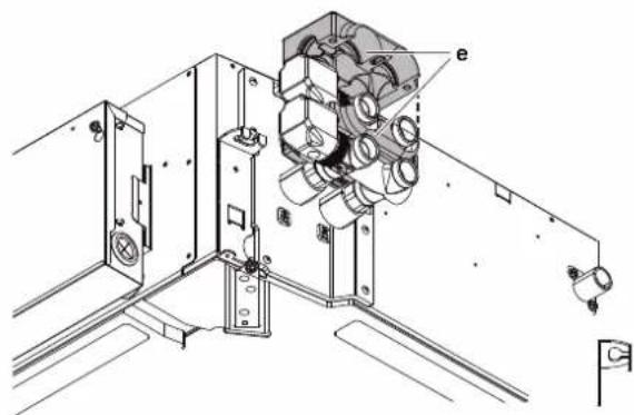
text_image
Technical diagram of a mechanical assembly with labeled components and directional arrowsnatural_image
Technical line drawing of a mechanical assembly with no visible text or symbolsnatural_image
Technical diagram of a mechanical assembly with four circular components and mounting holes (no text or labels)natural_image
Technical line drawing of an electrical enclosure with internal components and external wiring (no text or symbols)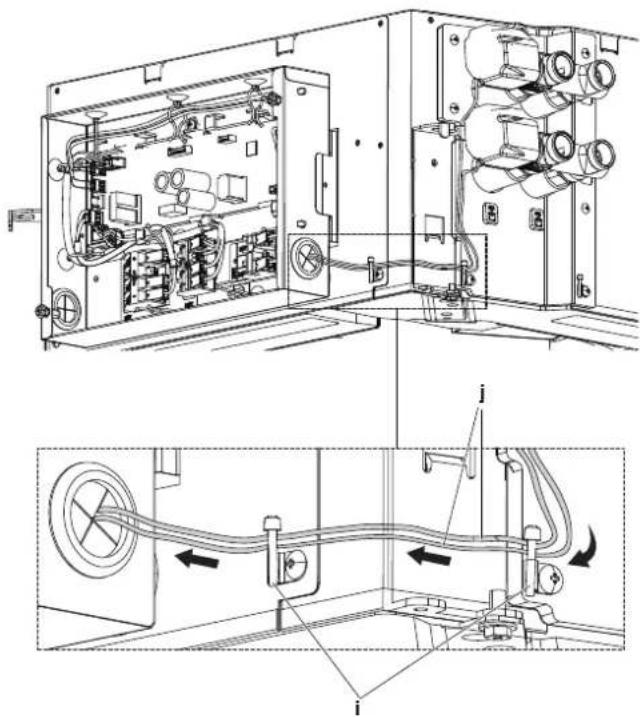
natural_image
Technical line drawing of an electrical enclosure with internal components and wiring, showing internal wiring connections (no text or labels)6 Porta-cabos (k). Ligue a válvula de refrigeração (etiqueta azul) à tomada X32A e o cabo da válvula de aquecimento à tomada X37A (I).
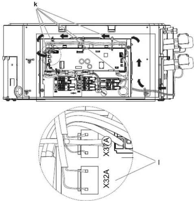
text_image
k X37A X32A Inatural_image
Technical line drawing of a mechanical device with a magnified inset showing a wheel and handle (no text or symbols)text_image
Technical diagram of an electrical enclosure with labeled components and wiring, showing internal layout and connections.natural_image
Interior view of an electronic device showing internal components and wiring (no text or labels visible)natural_image
Technical line drawing of an internal electronic device casing with visible wiring and components (no text or labels)natural_image
Technical line drawing of an internal electronic device casing with visible circuitry and wiring (no text or labels)6 Braçadeiras de cabos (c).
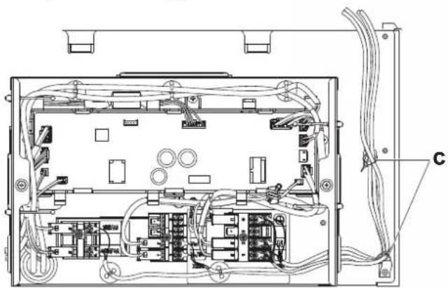
natural_image
Technical diagram of an electronic device interior showing internal components and wiring (no text or labels)7
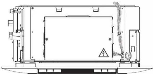
natural_image
Technical line drawing of a mechanical or electrical enclosure with no visible text, numbers, or symbols.7 Configuração
text_image
Illustration showing hands using a tablet to write documents, with a magnified view highlighting the paper's page layout.natural_image
Illustration of hands assembling a microchip with a magnified inset showing grid pattern (no text or symbols)text_image
Diagram illustrating a window expansion process with numbered steps and directional arrows indicating movement.text_image
Diagram illustrating a window grating mechanism with numbered steps and magnified views of the screen area.natural_image
Technical line drawing of a vacuum cleaner and a coiled solar panel with wires (no text or symbols)text_image
Exploded view diagram of a mechanical device with numbered components for identification17 Dados técnicos
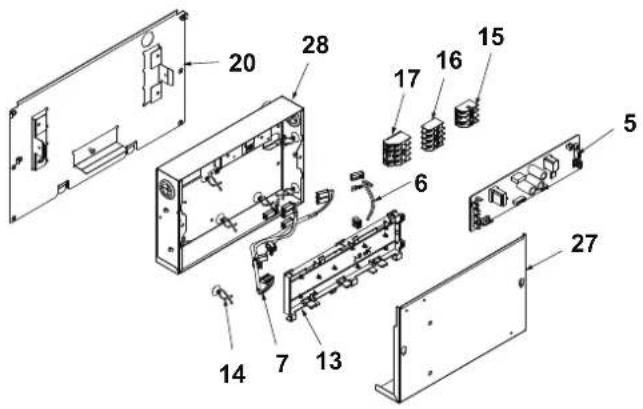
text_image
Exploded view diagram of an electronic device with numbered components for identificationnatural_image
Technical line drawing of a mechanical housing or enclosure with mounting brackets and internal components (no text or symbols)natural_image
Technical line drawing of a mechanical device with multiple arms and housing (no text or symbols)
ОБРАТИТЕ ВНИМАНИЕ
text_image
Technical diagram showing a hand operating a device with labeled parts and a cross symbol indicating failure or disassembly.natural_image
Technical line drawing of a mechanical housing or enclosure with mounting brackets and internal components (no text or symbols)text_image
Diagram showing a hand using a drill to install a floor panel, with labeled components and directional arrows.text_image
Technical diagram showing a geometric setup with labeled components (a, b, c, d) and an inset of a triangle with a horizontal line.natural_image
3D diagram of a layered structure with arrows indicating direction, no text or symbols present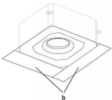
natural_image
Isometric diagram of concentric and nested layers forming a 3D cube-like structure (no text or symbols)natural_image
Mechanical component diagram showing a cylindrical shaft with hexagonal end and labeled part 'c' (no text or symbols beyond label)b a
text_image
Technical diagram showing mechanical assembly with labeled parts and a close-up of a component being inserted into a housing.text_image
1~1.5 m anatural_image
Technical line drawing of a mechanical assembly with no visible text or symbolsа Сливной патрубок
natural_image
Technical line drawing of an air conditioning unit with internal components and two inset views (a and b), no text or symbols present.text_image
Technical diagram showing mechanical assembly with labeled parts a, b, and c, including directional arrows and component arrangements.text_image
Technical diagram showing assembly of mechanical components with labeled parts a and b, including a magnified inset view.2 Приводные механизмы (d)
text_image
Technical diagram showing mechanical assembly with labeled components and directional arrows indicating motion or flowtext_image
Technical diagram showing mechanical assembly with labeled parts and exploded viewsnatural_image
Technical line drawing of a mechanical assembly with mounting brackets and a central component (no text or symbols)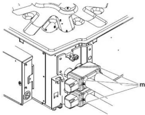
natural_image
Technical line drawing of a mechanical assembly with labeled components (no readable text or symbols)natural_image
Technical line drawing of an electrical enclosure with internal components and a close-up view of the interior (no text or symbols)text_image
Technical diagram of an electrical enclosure with labeled components and wiring connectionsnatural_image
Technical line drawing of a mechanical device with a magnified inset showing a circular component detail (no text or symbols)text_image
Technical diagram of an electronic device showing internal components and wiring, labeled with parts a and b.natural_image
Technical line drawing of an internal electronic device casing with visible circuitry and wiring (no text or labels)natural_image
Technical line drawing of an internal electronic device casing with visible circuitry and wiring (no text or labels)natural_image
Technical line drawing of an internal electronic device casing with visible wiring and components (no text or labels)natural_image
Technical diagram of an electronic device interior showing internal components and wiring (no text or labels)7
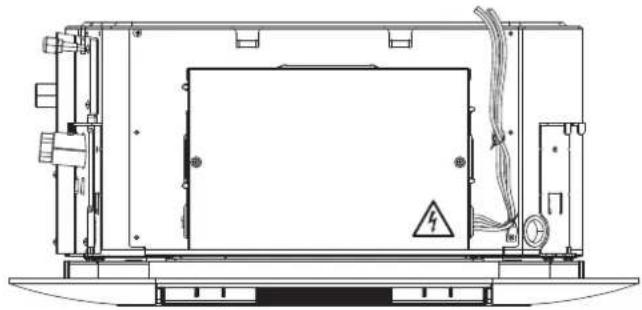
natural_image
Technical line drawing of an electrical enclosure with warning symbol and grounding device (no text or labels)7 Конфигурирование
natural_image
Technical line drawing of an electronic device interior showing exposed wiring, switches, and modules (no text or labels)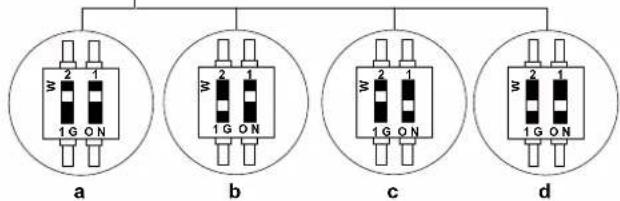
text_image
W 2 1 1G O N a W 2 1 1G O N b W 2 1 1G O N c W 2 1 1G O N dtext_image
Illustration showing hands using a tool to write or copy documents on a document, with a magnified view of the paper being edited.text_image
Diagram showing hands installing a grid pattern on a microchip, with an arrow indicating the process.text_image
Diagram illustrating airflow or ventilation system with numbered components and directional arrows indicating movementtext_image
Diagram illustrating a grid-based device with numbered components and directional arrows indicating assembly or installation steps.natural_image
Illustration of a vacuum tube connected to a solar panel and its wiring, showing components without any text or symbols.text_image
Exploded view diagram of a device with numbered components for identificationflowchart
graph TD
    subgraph "Indoor"
        L --> Q1R
        N --> Q2U
        Q1R --> F2U
        F2U --> X1M
        X1M --> BRN
        BRN --> BLU
        BLU --> BLK
        BLK --> GRN-YLW
        GRN-YLW --> X35A
        X35A --> X32A
        X32A --> X37A
        X37A --> X33A
        X33A --> BLU RED
        BLU RED --> X20A
        X20A --> X24A
        X24A --> PPL
        PPL --> BLK
        BLK --> COM
        COM --> Z1C
        Z1C --> MIF
        MIF --> MS
        MS --> H1P
        H1P --> DS1
        DS1 --> ON_OFF
        ON_OFF --> OFF
        OFF --> X50
        X50 --> X24A
        X24A --> PPL
        PPL --> BLK
        BLK --> COM
    end

    subgraph "Electronic Control - FWECSAC (OPTION)"
        A3P --> H3P
        H3P --> X4A
        X4A --> C1
        C1 --> N
        N --> X3A
        X3A --> H1P H2P
    end

    subgraph "ELECTRONIC BOARD - FWECSAP (OPTION) (NOTE 3)"
        A2P --> X4A
        A2P --> X2A
        A2P --> X1A
        A2P --> CA
    end

    subgraph "DECORATION PANEL - BYFQ000 (OPTION) (NOTE 2)"
        A5P --> X8A
        A5P --> X9A
        A5P --> X10A
    end

    subgraph "ADVANCED PLUS REMOTE CONTROLLER - FWECSA (OPTION) (NOTE 3)"
        A4P --> X7A
        A4P --> X6A
        A4P --> X5A
        A4P --> SWSWSA GA SU SU
    end

    subgraph "REDBL/BLK"
        X7A --> V1V1V2V3V4V5V6V7V8V9V10V11V12V13V14V15V16V17V18V19V20V21V22V23V24V25V26V27V28V29V30V31V32V33V34V35V36V37V38V39V40V41V42V43V44V45V46V47V48V49V50V51V52V53V54V55V56V57V58V59
    end

    subgraph "DESIGN" (Note 4)
        BNR --> X27A
        BNR --> F1U
        BNR --> Z1P
        Z1P --> V1R
        Z1R --> A1P
        A1P --> C305
        C305 --> PS
    end

    subgraph "MIP"
        MS --> X15A
        MS --> BLK
        MS --> S1L
        MS --> BSW
        BSW --> YLW
        BSW --> YLRW
        BSW --> YLRW
        BSW --> YLRW
        BSW --> YLRW
    end

    subgraph "MSW"
        MISW --> X36A
        MISW --> YLW
        MISW --> YLRW
        MISW --> YLRW
        MISW --> YLRW
    end

    subgraph "MIP"
        MIPW --> X25A3
        MIPW --> X36A3
        MIPW --> X3M3
    end

    subgraph "MIP"
        MIPWYBLSWLSWLSWLSWLSWLSWLSWLSWLSWLSWLSWLSWLSWLSWLSWLSWLSWLSWLSWLSWLSWLSWLSWLSWLSWLSWLSWLSWLSWLSWLSWLSWLSWLSWLSWLSWLSWLSWLSWLSWLSWLSWLSWLSWLSWLSWLSWLSWLSWLSWLSwLSwLSwLSwLSwLSwLSwLSwLSwLSwLSwLSwLSwLSwLSwLSwLSwLSwLSwLSwLSwLSwLSwLSwLSwLSwLSwLSwLSwLSwLSwLSwLSwLSwLSwLSwLSwLSwLSwLSwLSwLSwLSwLSwLSwLSwLSwLSwLSwLSwLSmSWSSWWSSWWSSWWSSWWSSWWSSWWSSWWSSWWSSWWSSWWSSWWSSWWSSWWSSWWSSWWSSWWSSWWSSWWSSWWSSWWSSWWSSWWSSWWSSWWSSWWSSWWSSWWSSWWSSWWSSWWSSWWSSWWSSWWSSWWSSWWSSWWSSWWSSWWSSWWSSWWSSWWSSWWSSWWSSWWSSWWSSWWSSWWSSWWSSWWSSWWSSwwsswwsswwsswwsswwsswwsswwsswwsswwsswwsswwsswwsswwsswwsswwsswwsswwsswwsswwsswwsswwsswwsswwsswwsswwsswwsswwsswwsswwsswwsswwsswwsswwsswwsswwsswwsswwsswwsswwsswwsswwsswwsswwsswwsswwsswwsswwsswwsswwsswwsswwslllllllllllllllllllllllllllllllllllllllllllllllllllllllllllllllllllllllllllllllllllllllllllllllllllllllllllllllllllllllllllllllllllllllllllllllllllllllllllllllllllll(l) & (Note 3)"
Замечания:
natural_image
Technical line drawing of a mechanical housing or enclosure with internal components and mounting brackets (no text or symbols)natural_image
Technical line drawing of a mechanical device with multiple arms and housing (no text or symbols)
DIKKAT
text_image
Technical diagram showing a hand operating a device with labeled components and a cross symbol indicating failure or disassembly.natural_image
Technical line drawing of a mechanical housing or enclosure with mounting brackets and internal components (no text or symbols)Model tanımlaması
Örnek: FW F 02 D A T N 5 V3 --
text_image
Diagram showing a hand using a drill to install a component, with labeled parts and directional arrows indicating movement.text_image
a b c d e Atext_image
Technical diagram showing a structural component with labeled parts a, b, c, d and an inset view of a triangular load distribution.natural_image
Technical line drawing of a mechanical or electrical enclosure with labeled components and dimensions (a, b), no readable text or symbols present.text_image
Technical diagram illustrating a multi-step assembly or installation process with labeled components and directional arrows indicating movement.text_image
Technical diagram showing mechanical assembly with labeled parts and a close-up of a component being inserted into a housing.text_image
1~1.5 m anatural_image
Technical line drawing of a mechanical assembly with mounting brackets and internal components (no text or symbols)a Drenaj soketi
natural_image
Technical line drawing of an air conditioning unit with internal components and labeled parts (a and b), showing internal structure and assembly details.a Silikon cam boru (dekoratif panel aksesuar setinde)
b Sargı bağlı (dekoratif panel aksesuar setinde)
text_image
Technical diagram showing assembly of mechanical components with labeled parts a, b, and ctext_image
Technical diagram showing assembly of mechanical components with labeled parts a and b, including a magnified inset view.2 Aktüatörler (d)
text_image
Technical diagram showing mechanical assembly with labeled component 'd' and directional arrows indicating motion or movement.natural_image
Technical line drawing of a mechanical assembly with labeled components (e and m), no readable text or symbols present.text_image
Technical diagram of a mechanical assembly with labeled components and directional arrows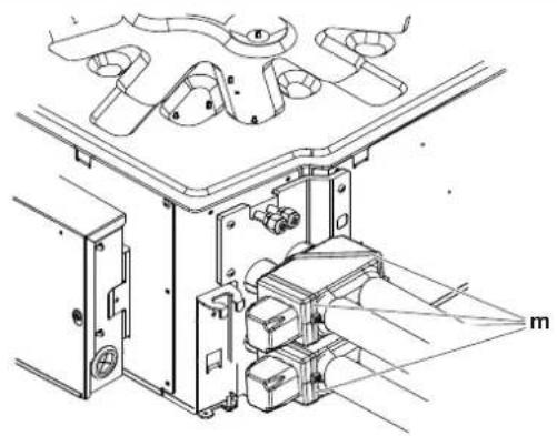
natural_image
Technical line drawing of an industrial machine assembly with no visible text or symbolsnatural_image
Technical line drawing of an electrical enclosure with internal components and a close-up view of the interior (no text or symbols)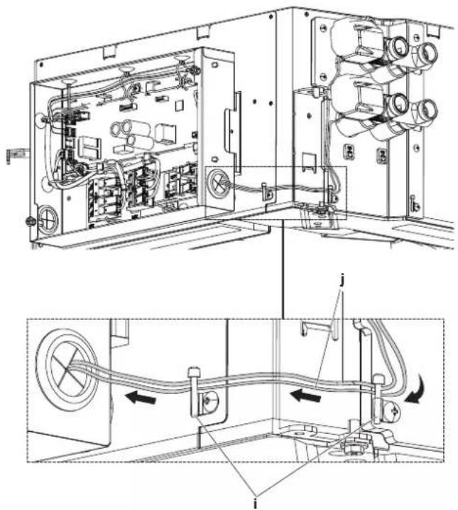
text_image
Technical diagram of an electrical enclosure with labeled components and wiring, showing internal wiring and connection details.natural_image
Technical line drawing of a mechanical device with a magnified inset showing a mechanical component (no text or symbols)7 Yapilandırma
natural_image
Interior view of an electronic device showing internal components and wiring (no text or symbols visible)natural_image
Interior view of an electronic device showing internal components and wiring (no text or labels visible)natural_image
Technical line drawing of an internal electronic device with exposed wiring and components (no text or labels)natural_image
Technical line drawing of an internal electronic device with exposed wiring and components (no text or labels)6 Kablo kelepçeleri (c).
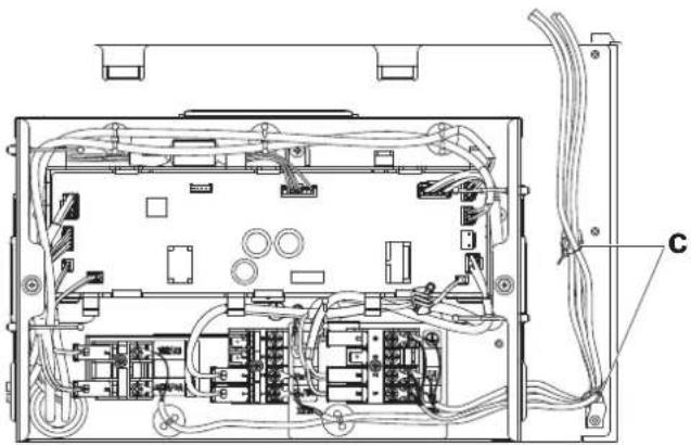
natural_image
Technical diagram of an electronic device interior showing internal components and wiring (no text or labels)7

natural_image
Technical line drawing of an electrical enclosure with warning symbol and grounding device (no text or labels)7 Yapilandırma
7.1 Dekoratif panel ayarı
natural_image
Technical line drawing of an electrical enclosure with internal components and wiring (no text or labels)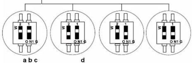
text_image
W 2 1 ON1$ a b c W 2 1 ON1$ d W 2 1 ON1$ W 2 1 ON1$a
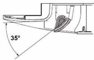
text_image
35°b
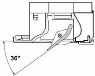
text_image
36°c
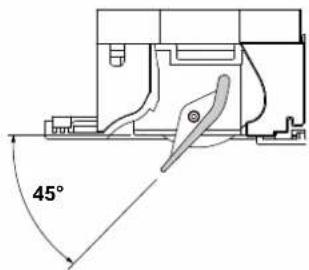
text_image
45°d
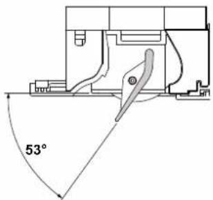
text_image
53°8 İşletmeye alma

DIKKAT
text_image
Illustration showing hands using a tool to write documents on a grid, with a magnified view of the document being edited.Tasarım paneli:
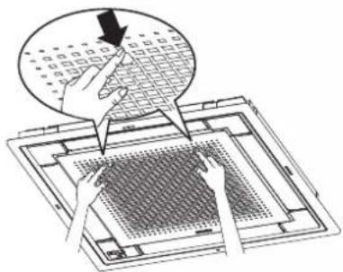
text_image
Diagram illustrating a process with hands installing or adjusting a grid-based component, labeled with Chinese text and an arrow pointing to the grid.text_image
Diagram illustrating airflow or ventilation system with numbered components and directional arrows indicating movementTasarım paneli:
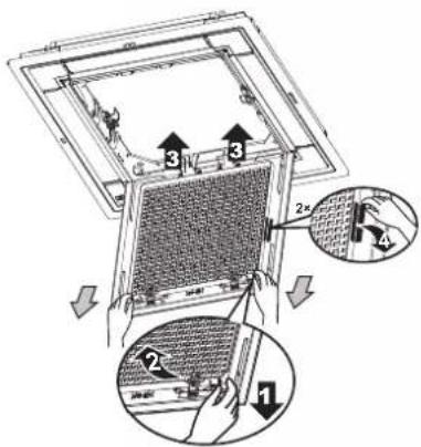
text_image
Diagram illustrating a window frame installation with numbered components and directional arrows indicating assembly or movement.natural_image
Technical line drawing of a vacuum cleaner connected to a solar panel and its corresponding circuit board (no text or symbols present)text_image
Exploded view diagram of a mechanical device with numbered components for identification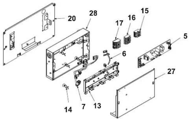
text_image
Exploded view diagram of an electronic device with numbered components for identificationflowchart
graph TD
    subgraph Indoor
        L --> Q1R
        N --> Q2U
        Q1R --> F2U
        F2U --> X1M
        X1M --> BRN
        BRN --> BLU
        BLU --> BLK
        BLK --> GRN-YLW
        GRN-YLW --> X35A
        X35A --> X32A
        X32A --> X37A
    end

    subgraph Electronic Control
        A3P --> H3P
        H3P --> X4A
        X4A --> C1
        C1 --> N
        N --> X3A
        X3A --> H1P H2P
    end

    subgraph Electronic Board
        A2P --> X4A
        A2P --> X1A
        A2P --> CA
        X4A --> C1
        X4A --> N
        X3A --> H1P H2P
    end

    subgraph Advanced Plus Remote Controller
        A4P --> X7A
        A4P --> X6A
        A4P --> X5A
        A4P --> SKSWSA5ASU SU
        A4P --> RIT
        RIT --> ADVANCEDPlusRemoteController
    end

    subgraph Decoration Panel
        A5P --> X8A
        A5P --> X9A
        X8A --> X10A
        X9A --> X10A
        X10A --> MSW
        X10A --> MSN
        X10A --> MSW
        X10A --> MSW
        X10A --> MSW
        X10A --> MSW
    end

    subgraph Power Supply
        A1M --> X1M
        N --> L --> +
    end

    subgraph Control Panel
        M1P --> X15A
        BLK --> BLK
        MIP --> MSW
        S1L --> M15
        MSW --> M15

    end

    style Indoor fill:#f9f,stroke:#333
    style Electronic Board fill:#ccf,stroke:#333
    style Advanced Plus Remote Controller fill:#cfc,stroke:#333