
EWWQ162KBW1N - Air-conditioner DAIKIN - Free user manual and instructions
Find the device manual for free EWWQ162KBW1N DAIKIN in PDF.

| Brand | Daikin |
| Model | EWWQ162KBW1N |
| Product type | Water-cooled chiller (air conditioner) |
| Nominal cooling capacity | Up to 64 kW (depending on version) |
| Dimensions (H x W x D) | 600 x 600 x 1200 mm (for high-capacity models) |
| Weight | Up to 340 kg |
| Power supply | 400 V 3N~ 50 Hz, recommended fuses 50 gG |
| Refrigerant | R410A, GWP 2090 |
| Compressor | Scroll type, speed 2900 rpm |
| Evaporator | Brazed plate heat exchanger |
| Condenser | Brazed plate heat exchanger |
| Functions | Cooling and heating (with reversing valve) |
| Control | Digital with display and keys, direct and user parameters |
| BMS connection | Modbus RS485 (optional kit) |
| Safety | Anti-freeze protection, HP/BP pressure switches, thermal protector, overload relay, flow switch |
| Recommended maintenance | Annual check: wiring, pressure, leaks, cleanliness of filters |
| Spare parts | Water filter, fuses, ball valves (available from dealer) |
| Repairability | Technical assistance by Daikin approved dealer |
Frequently Asked Questions - EWWQ162KBW1N DAIKIN
User questions about EWWQ162KBW1N DAIKIN
0 question about this device. Answer the ones you know or ask your own.
Ask a new question about this device
Download the instructions for your Air-conditioner in PDF format for free! Find your manual EWWQ162KBW1N - DAIKIN and take your electronic device back in hand. On this page are published all the documents necessary for the use of your device. EWWQ162KBW1N by DAIKIN.
USER MANUAL EWWQ162KBW1N DAIKIN
Packaged water-cooled water chillers

Operation manual
Packaged water-cooled water chillers
Bedienungsanleitung
Electrical specifications 2
Description 2
Function of the main components.... 3
Safety devices....3
Internal wiring - Parts table.... 4
Before operation....5
Checks before initial start-up 5
Water supply 5
General recommendations 5
Operation 5
Digital controller....5
Working with the units....6
Advanced features of the digital controller....9
BMS connection modbus 12
General description of Modbus.... 12
Implemented error code.... 13
Defining the BMS setting.... 13
Variables database 13
Troubleshooting.... 14
Maintenance.... 15
Important information regarding the refrigerant used 15
Maintenance activities 15
Disposal requirements.... 15
Menu overview.... 16

READ THIS MANUAL ATTENTIVELY BEFORE STARTING UP THE UNIT. DO NOT THROW THIS MANUAL AWAY. KEEP IT IN YOUR FILES FOR FUTURE REFERENCE.
Read the chapter "Operation" on page 5 before changing the parameters.
The English text is the original instruction. Other languages are translations of the original instructions.
This appliance is not intended for use by persons, including children, with reduced physical, sensory or mental capabilities, or lack of experience and knowledge, unless they have been given supervision or instruction concerning use of the appliance by a person responsible for their safety.
Children should be supervised to ensure that they do not play with the appliance.
INTRODUCTION
This operation manual concerns packaged water-cooled water chillers of the Daikin EWWQ-KB series. These units are provided for indoor installation and used for cooling and/or heating applications. The units can be combined with Daikin fan coil units or air handling units for air conditioning purposes. They can also be used for supplying water for process cooling.
This manual has been prepared to ensure adequate operation and maintenance of the unit. It will tell you how to use the unit properly and will provide help if problems occur. The unit is equipped with safety devices, but they will not necessarily prevent all problems caused by improper operation or inadequate maintenance.
In case of persisting problems contact your local Daikin Dealer.

Before starting up the unit for the first time, make sure that it has been properly installed. It is therefore necessary to carefully read the installation manual supplied with the unit and the recommendations listed in "Before starting".
Technical specifications ^(1)
| General EWWQ 014 025 033 | ||
| Dimensions HxWxD (mm) | 600x600x600 | |
| Machine weight (kg) | 120 170 175 | |
| Connections | ||
| • w a t er inlet | G 1 | |
| • w a t er outlet | G 1 | |
| General EWWQ | 049 | 064 | |
| Dimensions HxWxD | (mm) | 600x600x1200 | |
| Machine weight | (kg) | 310 | 340 |
| Connections | |||
| • w a t er inlet | G 1-1/2 | ||
| • w a t er outlet | G 1-1/2 | ||
| Compressor | 014 025 033 | |||
| Model | JT140L-P8Y1 | JT236DJ-Y1 | JT315DJ-Y1 | |
| Speed | (rpm) | 2900 | ||
| Oil type | FVC68D | |||
| Oil charge volume | (l) | 1.5 | 3.0 | 3.0 |
| Refrigerant type | R410A | |||
| Refrigerant charge | (kg) | 1.2 | 2.1 | 3.1 |
| Evaporator | 014 025 033 | |||
| Type | brased plate heat exchanger | |||
| Min. water volume | (l) | 62 | 103 155 | |
| Water flow range | (l/min) | 31~75 | 53~123 | 76~186 |
| Condenser | 014 025 033 | |||
| Type | brased plate heat exchanger | |||
| Water flow range | (l/min) | 24~95 | 39~157 | 59~237 |
| Compressor | 049 | 064 | |||
| Model | 2x JT236DJ-Y1 | 2x JT315DJ-Y1 | |||
| Speed | (rpm) | 2900 | |||
| Oil type | FVC68D | ||||
| Oil charge volume | (l) | 2x 3.0 | 2x 3.0 | ||
| Refrigerant type | R410A | ||||
| Refrigerant charge | (kg) | 4.6 | 5.6 | ||
| Evaporator | 049 | 064 | |
| Type | brased plate heat exchanger | ||
| Min. water volume | (l) | 205 | 311 |
| Water flow range | (l/min) | 101~247 | 152~373 |
| Condenser | 049 | 064 | |
| Type | brased plate heat exchanger | ||
| Water flow range | (l/min) | 79~314 | 118~474 |
Electrical specifications ^(1)
| General EWWQ 014 025 033 | ||||
| Power supply | ||||
| • Phase 3N~ | ||||
| • Frequency (Hz) | 50 | |||
| • Voltage (V) | 400 | |||
| • Voltage tolerance (%) | ±10 | |||
| • Recommended fuses (aM) | 16 gG | 25 gG | 25 gG | |
| Compressor | ||||
| • Phase 3~ | ||||
| • Frequency (Hz) | 50 | |||
| • Voltage (V) | 400 | |||
| • Nominal running current (A) | 6.5 | 10.5 | 15.0 | |
| Control | ||||
| • Phase 1~ | ||||
| • Frequency (Hz) | 50 | |||
| • Voltage (V) | 230 | |||
| • Recommended fuses (aM) | factory installed | |||
| General EWWQ | 049 | 064 | |
| Power supply | |||
| • Phase | 3N~ | ||
| • Frequency (Hz) | 50 | ||
| • Voltage (V) | 400 | ||
| • Voltage tolerance (%) | ±10 | ||
| • Recommended fuses (aM) | (AM) | 40 gG | 50 gG |
| Compressor | |||
| • Phase | 3~ | ||
| • Frequency (Hz) | 50 | ||
| • Voltage (V) | 400 | ||
| • Nominal running current (A) | (A) | 10.5 | 15.0 |
| Control | |||
| • Phase | 1~ | ||
| • Frequency (Hz) | 50 | ||
| • Voltage (V) | 230 | ||
| • Recommended fuses (aM) | factory installed | ||
DESCRIPTION
The EWWQ packaged water-cooled water chillers are available in 5 standard sizes with nominal cooling capacities ranging from 13 to 64 kW.
EWWQ014\~033KB
EWWQ049\~064KB
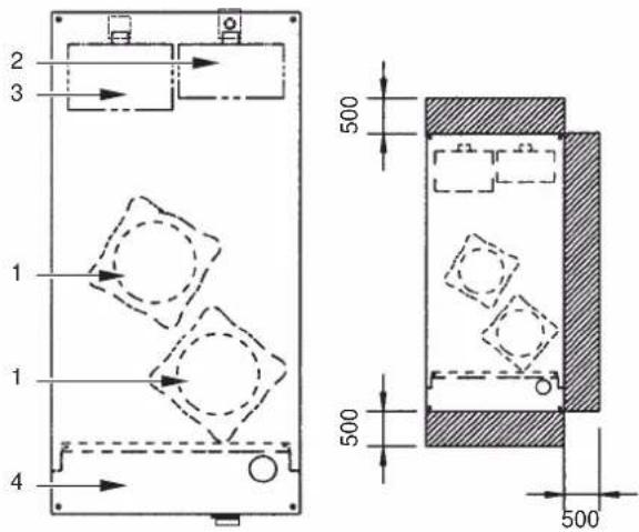
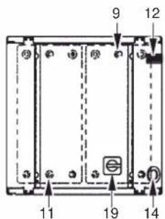
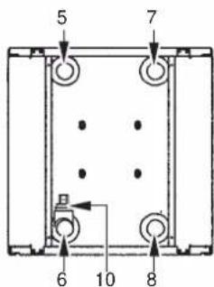
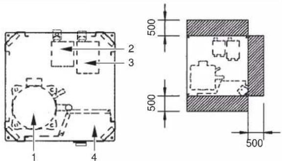
Figure - Main components
| 1 | Compressor |
| 2 | Evaporator |
| 3 | Condenser |
| 4 | Switchbox |
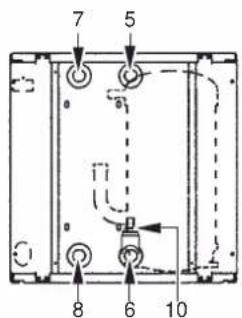
| 5 | Chilled water in |
| 6 | Chilled water out |
| 7 | Condenser water out |
| 8 | Condenser water in |
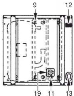
| 9 | Evaporator entering water temperature sensor |
| 10 | Freeze up sensor |
11 Condenser entering water temperature sensor
12 Digital display controller
13 Power supply intake
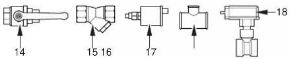
14 Ball valve (field installed)
15 Water filter (field installed)
16 Air purge valve (field installed)
17 T-joint for air purge (field installed)
18 Flow switch (with T-joint) (field installed)
19 Main switch
Required space around the unit for service
(1) Refer to the engineering data book for the complete list of specifications.
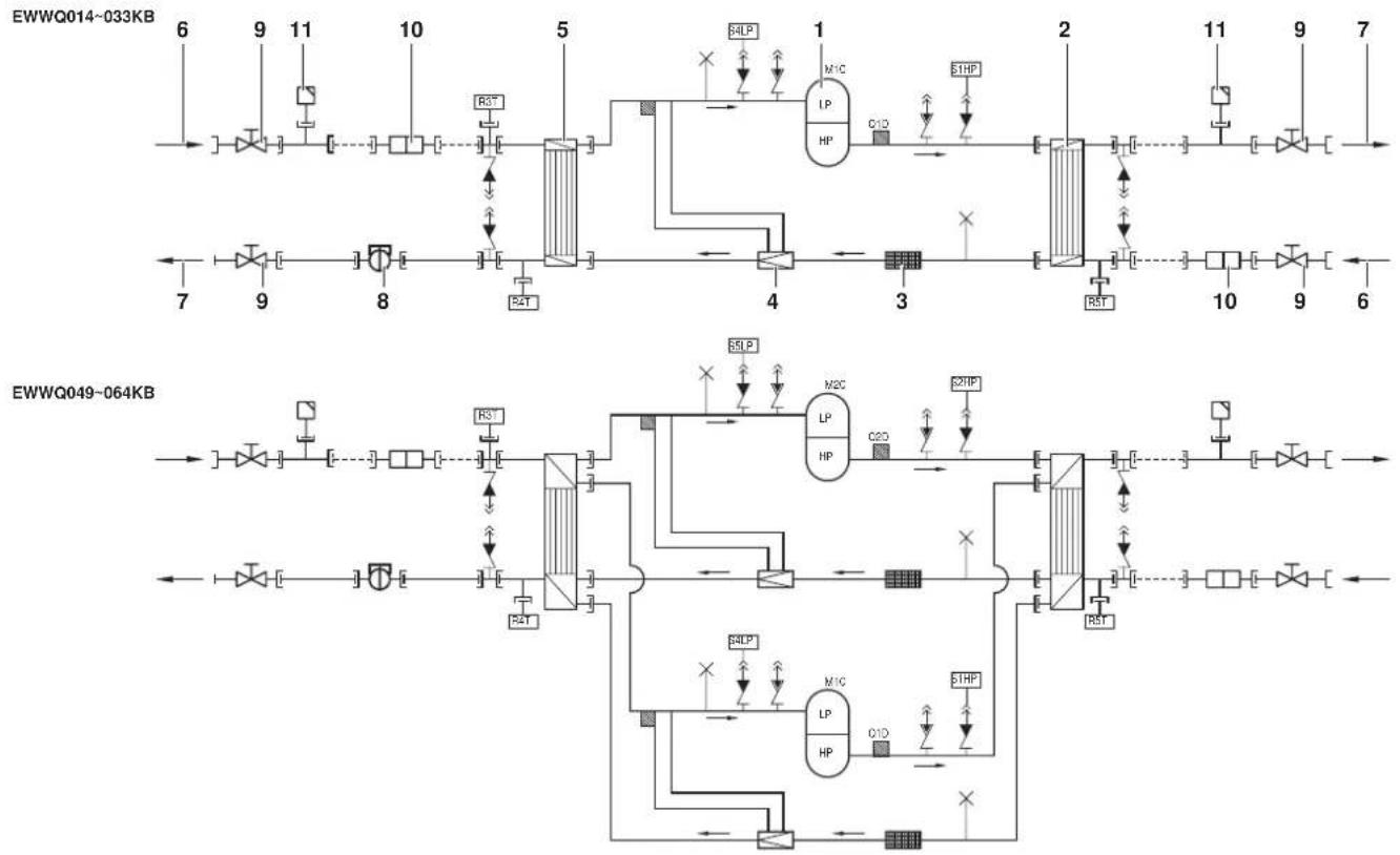
Function of the main components
flowchart
graph TD
    subgraph_EWWQ014-033KB["EDWQ014-033KB"]
        A["6"] --> B["9"] --> C["11"] --> D["10"] --> E["5"] --> F["4"] --> G["2"] --> H["11"] --> I["9"] --> J["7"]
        K["7"] --> L["9"] --> M["8"] --> N["4"] --> O["3"] --> P["10"] --> Q["9"] --> R["6"]
        S["RST"] --> T["RST"]
        U["RST"] --> V["RST"]
        W["RST"] --> X["RST"]
        Y["RST"] --> Z["RST"]
        AA["RST"] --> AB["RST"]
        AC["RST"] --> AD["RST"]
        AE["RST"] --> AF["RST"]
        AG["RST"] --> AH["RST"]
        AI["RST"] --> AJ["RST"]
        AK["RST"] --> AL["RST"]
        AM["RST"] --> AN["RST"]
        AO["RST"] --> AP["RST"]
        AQ["RST"] --> AR["RST"]
        AS["RST"] --> AT["RST"]
        AU["RST"] --> AV["RST"]
        AW["RST"] --> AX["RST"]
        AY["RST"] --> AZ["RST"]
        BA["RST"] --> BB["RST"]
        BC["RST"] --> BD["RST"]
        BE["RST"] --> BF["RST"]
        BG["RST"] --> BH["RST"]
        BI["RST"] --> BJ["RST"]
        BK["RST"] --> BL["RST"]
        BM["RST"] --> BN["RST"]
        BO["RST"] --> BP["RST"]
        BZ["RST"] --> CA["RST"]
        CB["RST"] --> CD["RST"]
        CE["RST"] --> CF["RST"]
        GD["RST"] --> DH["RST"]
        DI["RST"] --> DJ["RST"]
        DK["RST"] --> DL["RST"]
        DV["RST"] --> DVRA["RST"]
        DW["RST"] --> DWAVR["HP"]
        DX["RST"] --> DXAVR["HP"]
        DXV["HP"] --> DXV["HP"]
        DXV --> DXV["HP"]
        DXV --> DXV["HP"]
        DXV --> DXV["HP"]
        DXV --> DXV["HP"]
        DXV --> DXV["HP"]
        DXV --> DXV["HP"]
        DXV --> DXV["HP"]
        DXV --> DXV["HP"]
        DXV --> DXV["HP"]
    end
    subgraph_EWWQ049-064KB["EDWQ049-064KB"]
        E["6"] --> F["9"] --> G["11"] --> H["10"] --> I["5"] --> J["4"] --> K["3"] --> L["2"] --> M["11"] --> N["9"] --> O["7"]
        P["7"] --> Q["9"] --> R["8"] --> S["4"] --> T["3"] --> U["10"] --> V["9"] --> W["6"]
        X["5"] --> Y["9"] --> Z["8"] --> AA["4"] --> AB["3"] --> AC["10"] --> AD["9"] --> AE["6"]
        AF["5"] --> AG["9"] --> AH["8"] --> AI["4"] --> AJ["3"] --> AK["10"] --> AL["9"] --> AM["6"]
        AN["5"] --> AO["9"] --> AP["8"] --> AQ["4"] --> AR["3"] --> AS["10"] --> AT["9"] --> AU["6"]
        AV["5"] --> AW["9"] --> AX["8"] --> AY["4"] --> AZ["3"] --> BA["10"] --> BB["9"] --> BC["6"]
        AD["5"] --> BD["9"] --> BE["8"] --> BF["4"] --> BG["3"] --> BH["10"] --> BI["9"] --> BJ["6"]
        AC["5"] --> BK["9"] --> BL["8"] --> BM["4"] --> BN["3"] --> BO["10"] --> BP["9"] --> BQ["6"]
        DA["5"] --> DB["9"] --> BEB["B3T"]
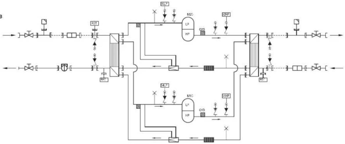
Figure - Functional diagram
1 Compressor 7 Water outlet
2 Condenser
3 Filter
4 Expansion valve
5 Evaporator
6 Water inlet Field piping
As the refrigerant circulates through the unit, changes in its state or condition occur. These changes are caused by the following main components:
■ Compressor
The compressor (M*C) acts as a pump and circulates the refrigerant in the refrigeration circuit. It compresses the refrigerant vapour coming from the evaporator to a pressure at which it can easily be liquefied in the condenser.
■ Condenser
The function of the condenser is to change the state of the refrigerant from gaseous to liquid. The heat gained by the gas in the evaporator is discharged through the condenser and the vapour condenses to liquid.
■ Filter
The filter installed behind the condenser removes small particles from the refrigerant to prevent blockage of the tubes.
■ Expansion valve
The liquid refrigerant coming from the condenser enters the evaporator via an expansion valve. The expansion valve brings the liquid refrigerant to a pressure at which it can easily be evaporated in the evaporator.
■ Evaporator
The main function of the evaporator is to take heat from the water that flows through it. This is done by turning the liquid refrigerant, coming from the condenser, into gaseous refrigerant.
■ Water in/outlet connections
The water inlet and outlet connection allow an easy connection of the unit to the water circuit of the air handling unit or industrial equipment.
8 Flow switch (delivered with the unit, installed in the field)
9 Ball valve (delivered with the unit, installed in the field)
10 Water filter (delivered with the unit, installed in the field)
11 Air purge valve (delivered with the unit, installed in the field)
Safety devices
The unit is equipped with General safety devices: shut down all circuits and stop the whole unit.
■ I/O PCB (A2P) (input/output)
The I/O PCB (A2P) contains a reverse phase protector. The reverse phase protector detects if the 3 phases of the power supply are connected correctly. If a phase is not connected or if 2 phases are inverted, the unit can not start up.
■ Overcurrent relay
The overcurrent relay (K*S) is located in the switch box of the unit and protects the compressor motor in case of overload, phase failure or too low voltage. The relay is factory-set and may not be adjusted. When activated, the overcurrent relay has to be reset in the switch box and the controller needs to be reset manually.
■ High-pressure switch
The high-pressure switch (S*HP) is installed on the discharge pipe of the unit and measures the condenser pressure (pressure at the outlet of the compressor). When the pressure is too high, the pressure switch is activated and the circuit stops. When activated, it resets automatically, but the controller needs to be reset manually.
■ Low pressure switch
The low-pressure switch (S*LP) is installed on the suction pipe of the unit and measures the evaporator pressure (pressure at the inlet of the compressor). When the pressure is too low, the pressure switch is activated and the circuit stops.
When activated, it resets automatically, but the controller needs to be reset manually.
■ Discharge thermal protector
The discharge thermal protector (Q*D) is activated when the temperature of the refrigerant leaving the compressor becomes too high. When the temperature returns to normal, the protector resets automatically, but the controller needs to be reset manually.
■ Freeze up sensor
The outlet water temperature sensor (R4T) measures the temperature of the water at the water heat exchanger outlet. The protection device shuts down the circuit when the temperature of the chilled water becomes too low in order to prevent freezing of the water during operation.
When the outlet water temperature returns to normal, the protector resets automatically, but the controller needs to be reset manually.
■ Fuse for control circuit (F1U)
The fuse for control circuit protects cables of control circuit and controller components in case of short circuit.
■ Fuse for control circuit (F4)
The fuse for the control circuit protects cables of the control circuit in case of a short circuit.
■ Fuse for digital controller (F3U)
The fuse protects cables of digital controller and digital controller in case of short circuit.
■ Flow switch (delivered with the unit, installed in the field)
The flow switch measures the flow in the water circuit. In case the flow does not reach the minimum allowed water flow, the unit will be shut down.
■ Ball valve (delivered with the unit, installed in the field)
A ball valve is installed in front of and behind the water filter to allow filter cleaning without having to drain the water circuit.
■ Water filter (delivered with the unit, installed in the field)
The filter installed in front of the unit removes dirt from the water to prevent damage to the unit or blockage of the evaporator or condenser. The water filter should be cleaned on a regular base.
■ Air purge valve (delivered with the unit, installed in the field)
Remaining air in the chiller water system will be automatically removed via the air purge valve.
Internal wiring - Parts table
Refer to the internal wiring diagram supplied with the unit. The abbreviations used are listed below:
A1P.... PCB: controller PCB
A2P.... PCB: I/O PCB (input/output)
A3P....** .... PCB: Address card for BMS ^(1)
A5P,A6P.....** ..... PCB: Softstarter for circuit 1, circuit 2 ^(1)
A7P....** .... PCB: Remote user interface ^(1)
A71P.... PCB: power supply card
A72P.... PCB: remote user interface
F1,F2,F3.....# ..... Main fuses for the unit ^(2)
F4 ....* ..... Fuse I/O PCB
F5 ......## ...... Surge proof fuse
F6 ......# ...... Fuse for pumpcontactor(2)
F1U..... Fuse I/O PCB
F3U..... Fuse for controller PCB
H3P....* .... Indication lamp alarm ^(2)
H4P....* ..... Indication lamp operation compressor 1 ^(2)
H5P....* ..... Indication lamp operation compressor 2 ^(2)
H6P....* ..... Indication lamp general operation ^(2)
K1M,K2M..... Compressor contactor circuit 1, circuit 2
K4S,K5S...... Overcurrent relay circuit 1, circuit 2
K6S....* .... Overcurrent relay pump ^(2)
K1P...... * ...... Pumpcontactor
M1C,M2C...... Compressor motor circuit 1, circuit 2
PE.... Main earth terminal
Q1D,Q2D ...... Discharge thermal protector circuit 1, circuit 2
R3T...... Evaporator inlet water temperature sensor
R4T...... Evaporator outlet water temperature sensor
R5T...... Condenser inlet temperature sensor
S1HP,S2HP.... High pressure switch circuit 1, circuit 2
S4LP,S5LP.... Low pressure switch circuit 1, circuit 2
S7S...... * .... Switch for remote cooling/heating selection or dual setpoint ^(2)
S9S..... * ..... Switch for remote start/stop or dual setpoint ^(2)
S10L ...... Flow switch
S12M ...... Main isolator switch
TR1.... Transfo 230 V → 24 V for supply of controller PCB
TR2.... Transfo 230 V → 24 V for supply of I/O PCB (A2P)
Y3R...... Reversing valve
X1\~3,X1\~82A ...... Connectors
| Not included with standard unit | ||
| Not possible as option Possible as option | ||
| Obligatory # ## | ||
| Not obligatory * * | ||
(1) optional
(2) field supply
BEFORE OPERATION
Checks before initial start-up

Make sure that the circuit breaker on the power supply panel of the unit is switched off.
After the installation of the unit, check the following before switching on the circuit breaker:
1 Field wiring
Make sure that the field wiring between the local supply panel and the unit has been carried out according to the instructions described in the installation manual, according to the wiring diagrams and according to European and national regulations.
2 Fuses or protection devices
Check that the fuses or the locally installed protection devices are of the size and type specified in the installation manual. Make sure that neither a fuse nor a protection device has been bypassed.
3 Earth wiring
Make sure that the earth wires have been connected properly and that the earth terminals are tightened.
4 Internal wiring
Visually check the switch box on loose connections or damaged electrical components.
5 Fixation
Check that the unit is properly fixed, to avoid abnormal noises and vibrations when starting up the unit.
6 Damaged equipment
Check the inside of the unit on damaged components or squeezed pipes.
7 Refrigerant leak
Check the inside of the unit on refrigerant leakage. If there is a refrigerant leak, call your local dealer.
8 Oil leak
Check the compressor on oil leakage. If there is an oil leak, call your local dealer.
9 Power supply voltage
Check the power supply voltage on the local supply panel. The voltage should correspond to the voltage on the identification label of the unit.
Water supply
Fill the water piping, taking into account the minimum water volume required by the unit. Refer to the chapter "Water charge, flow and quality" in the installation manual.
Make sure that the water is of the quality as mentioned in the installation manual.
Purge the air at the high points of the system and check the operation of the circulation pump and the flow switch.
General recommendations
Before switching on the unit, read following recommendations:
1 When the complete installation and all necessary settings have been carried out, close all front panels of the unit.
2 The service panel of the switch box may only be opened by a licensed electrician for maintenance purposes.
OPERATION
The EWWQ units are equipped with a digital controller offering a user-friendly way to set up, use and maintain the unit.
This part of the manual has a task-oriented, modular structure. Apart from the first section, which gives a brief description of the controller itself, each section or subsection deals with a specific task you can perform with the unit.
Digital controller
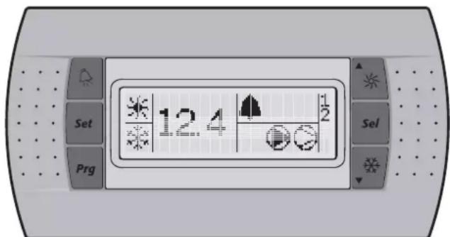
User interface
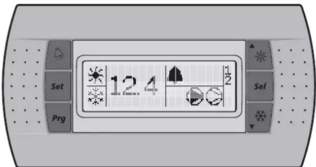
The digital controller consists of a numeric display, four labelled keys which you can press and LEDs providing extra user information.
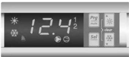
Figure - Digital controller
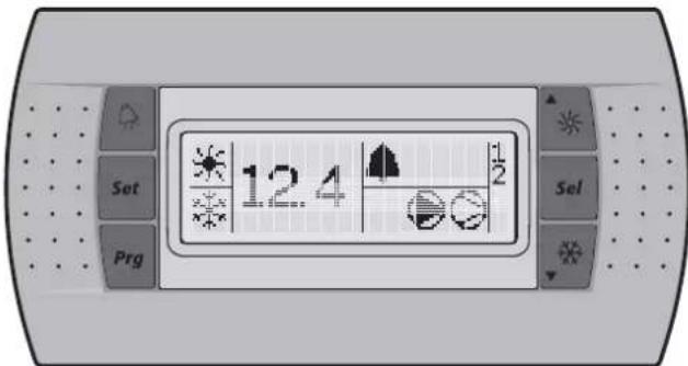
Figure - Remote user interface (optional kit)
Keys provided on the controller:
The function carried out when the user presses one or a combination of these keys depends on the status of the controller and the unit at that specific moment.
| Keys digital controller | Keys remote interface | Main display | Sensor readout menu | Parameter selection menu | Parameter setting menu |
| — Press once: | Return | Press once: Return | Press once: Cancel and return | ||
| Press for 5 seconds: To be able to access DIRECT parameters | — | Press once: Select parameter group or parameter | Press once: Confirm and return | ||
 | Press for 5 seconds: SE + OR Press once: To be able to access USER parameters (after entering USER password) | — | |||
 |  | Press for 5 seconds: Switch unit on/off in heating modePress once: Direct access to readout menu sensor(b0 1/602/603) | Press once: Select previous sensor parameter | Press once: Select previous parameter group or parameter | Press once: Increase value |
| Press for 5 seconds: Switch unit on/off in cooling modePress once: Direct access to readout menu sensor(b0 1/602/603) | Press once: Select next sensor parameter | Press once: Select next parameter group or parameter | Press once: Decrease value | ||
 | Press for 5 seconds: Manually alarm reset in the event of alarm | — | |||
LEDs provided on the controller and remote interface:
Function during main display (not inside menu)
| Leds digital controller | Remote interface | Main display | |
| 12.4 | Led (green) 12 | 4 Inlet water temp | erature. |
| ※ | Led (amber) | ※ | Indicates that heating mode is active. |
 | Indicates that cooling mode is active. | ||
| Led (red) | Indicates that the alarm is active. | ||
| con | Led (amber) | Indicates the status of the pump | |
| ### | Led (amber) | LED, indicates that at least one compressor is active. | |
| ### | Led (amber) | 1 | LED is on, indicates that compressor 1 is active.LED is flashing, indicates compressor 1 startup request. |
| 2 | Led (amber) | 2 | LED is on, indicates that compressor 2 is active.LED is flashing, indicates compressor 2 startup request. |
When selecting a parameter group or parameter, different LEDs related to the parameter group or parameter are displayed.
Example: The LEDs ✦ and ✦ are displayed when accessing a parameter group or when accessing parameters directly.
NOTE

Temperature readout tolerance: ±1°C.
Legibility of the numeric display may decrease in direct sunlight.
Direct and user parameters
The digital controller provides direct and user parameters. The direct parameters are important for the everyday usage of the unit, e.g. to adjust the temperature setpoint or to consult actual operational information. The user parameters on the contrary provide advanced features such as adjusting time delays.
Each parameter is defined by a code and a value. For example: the parameter used to select local or remote on/off control has code HO7 and value I or O.
For an overview of the parameters, refer to "Overview of the direct and user parameters" on page 9.
Working with the units
This chapter deals with the everyday usage of the units. Here, you will learn how to perform routine tasks, such as:
■ "Switching the unit on" on page 7 and "Switching the unit off" on page 7,
■ "Adjusting the cooling temperature setpoint" on page 7 and "Adjusting the heating temperature setpoint" on page 7,
■ "Consulting actual operational information" on page 8,
■ "Resetting alarms" on page 8,
■ "Resetting warnings" on page 8.
Switching the unit on
To switch the unit on in cooling mode, proceed as follows:
1 Press the ⚙▼ key for approximately 5 seconds, the ⚙ LED will be displayed.
To switch the unit on in heating mode, proceed as follows:
1 Press the ▲※ key for approximately 5 seconds, the ✗ LED will be displayed.
In both cases an initialization cycle is started, the LED, the LED, the 1 LED and the 2 LED will light up depending on the programmed thermostat function.
In case the 1 LED or the 2 LED is flashing, it indicates that there is a compressor 1 or 2 startup request. The compressor will start after the timer has reached zero.
NOTE

If remote on/off control is enabled, refer to "Selecting local or remote on/off control" on page 11.
2 When the unit is started up for the first time, or when the unit has been out of operation for a longer period, it is recommended to go through the following checklist.
Abnormal noise and vibrations
Make sure the unit does not produce any abnormal noises or vibrations: check the fixations and piping. If the compressor makes any abnormal noises, this may also be caused by an overcharge of refrigerant.
Working pressure
It is important to check the high and low pressure of the refrigerant circuit to ensure the proper operation of the unit and to guarantee that the rated output will be obtained.

The pressures measured will vary between a maximum and minimum value, depending on the water and outdoor temperatures (at the moment of measurement).
3 If the unit does not start after a few minutes, consult the actual operational information available in the list of direct parameters. Also refer to the chapter "Troubleshooting" on page 14.
NOTE

In case of remote on/off control (H07=1), it is recommended to install an on/off switch near the unit in series with the remote switch. The unit can then be switched off from either place.
The selection of cooling mode or heating mode can only be carried out at startup. Selecting an opposite mode without switching the unit off is impossible.
Switching the unit off
To switch the unit off and cooling mode is active, proceed as follows:
1 Press the ⚙▼ key for approximately 5 seconds, the ⚙ LED will be extinguished.
To switch the unit off and heating mode is active, proceed as follows:
1 Press the ▲★ key for approximately 5 seconds, the ✱ LED will be extinguished.
NOTE

If remote on/off control is enabled, refer to "Selecting local or remote on/off control" on page 11.
How to consult and modify the direct parameters
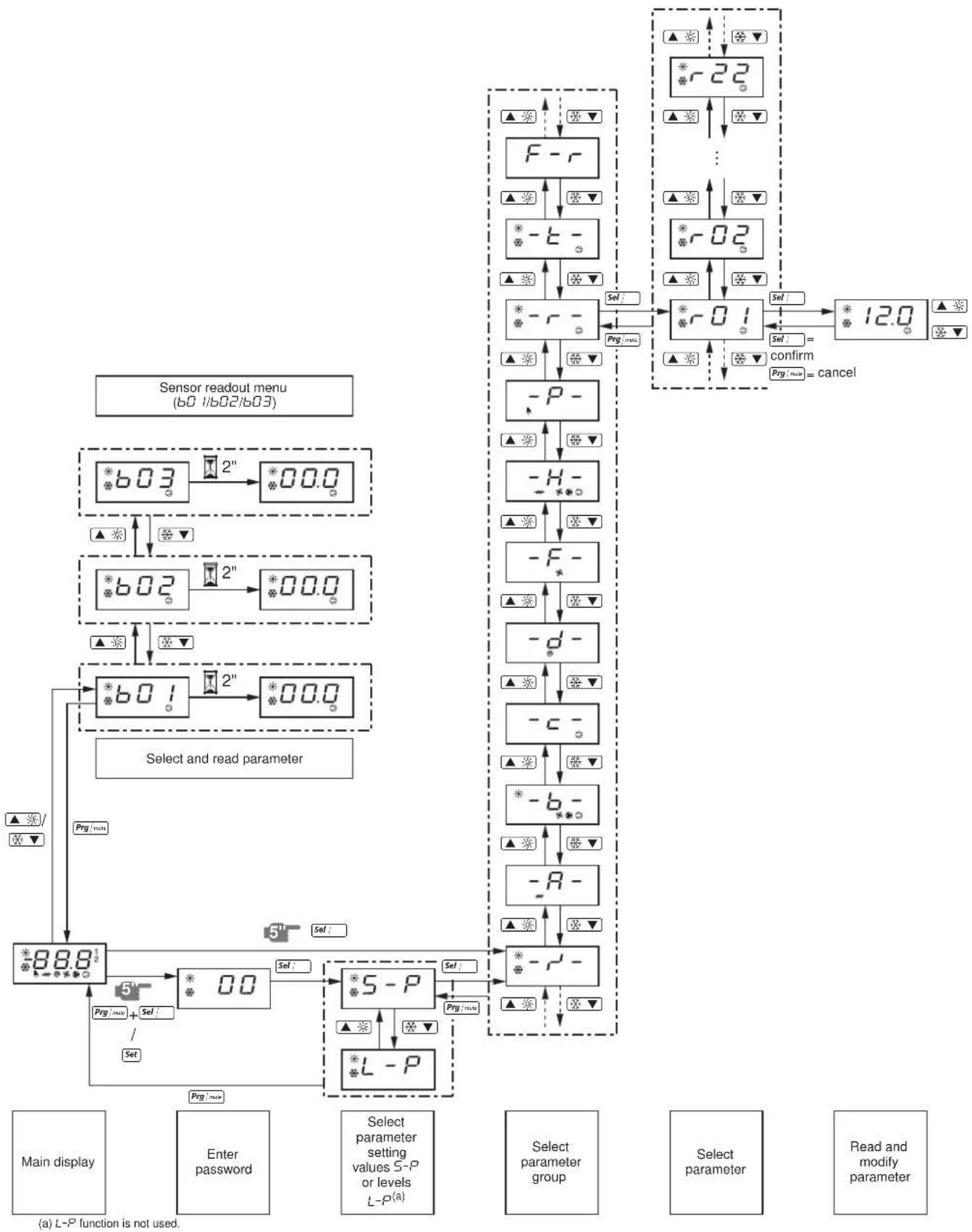
For an overview of the menu structure, refer to "Menu overview" on page 16.
1 Press Sel; for 5 seconds in the main display. The -r'- parameter group is displayed.
2 Press the ▲※ or ⚙▼ key to select the required parameter group.
3 Press the Sel key to enter the selected parameter group.
4 Press the ▲※ or ⚙▼ key to select the required parameter.
5 Press the Sel key to consult the selected parameter.
6 Press the ▲ or ⚙▼ key to raise, respectively lower the setting of the selected parameter. (Only valid for read/write parameters.)
7 Press the Sal key to confirm the modified setting. OR Press the Prg key to cancel the modified setting.
8 Press the _i n key to return to the parameter group.
9 Press 2 times the | w key to return to the main display.
If during the procedure no buttons are pressed for 30 seconds, the displayed parameter code or value will start flashing. After another 30 seconds without pressing any buttons, the controller automatically returns to the main display without saving any modified parameter.
How to consult the "sensor readout menu" parameters
For an overview of the menu structure, refer to "Menu overview" on page 16.
The 60 1/602/603 parameters are part of the "sensor readout menu".
1 Press the ▲ or ⚙▼ key in the main display.
The 601 parameter is displayed.
In case no buttons are pressed, the value of the b01 sensor will be displayed until ▲※ or ※▼ is pressed again to select another parameter (b02 or b03).
2 Press the ram key to return to the main display.
If during the procedure no buttons are pressed for 30 seconds, the displayed parameter code or value will start flashing. After another 30 seconds without pressing any buttons, the controller automatically returns to the main display.
Adjusting the cooling temperature setpoint
1 Modify the r / I cooling setpoint parameter.
This is a direct parameter, refer to "How to consult and modify the direct parameters" on page 7.
NOTE
When dual setpoint is enabled (refer to "Selecting dual setpoint control" on page 11).

Adjusting the heating temperature setpoint
1 Modify the r-3 heating setpoint parameter.
This is a direct parameter, refer to "How to consult and modify the direct parameters" on page 7.
NOTE
When dual setpoint is enabled (refer to "Selecting dual setpoint control" on page 11).

Consulting actual operational information
The actual operational information that can be consulted in the list of direct parameters consists of:
■ 601: Evaporator inlet water temperature,
■ 602: Evaporator outlet water temperature,
■ b03: When cooling mode is active: inlet water temperature of the condenser. When heating mode is active: inlet water temperature of the evaporator.
■ c 10: Total running hours of the compressor 1,
■ c / /: Total running hours of the compressor 2,
■ c 15: Total running hours of the pump.
NOTE

The parameters 601, 602 and 603 can also be consulted by the "sensor readout menu". Refer to "How to consult the "sensor readout menu" parameters" on page 7.
■ To reset the timers of parameters c 10, c 11 and c 15 refer to "Resetting warnings" on page 8.
These are direct parameters, refer to "How to consult and modify the direct parameters" on page 7.
Resetting alarms
When an alarm is detected, the following happens:
■ the alarm relay is energized,
■ the LED is displayed
■ the display starts flashing, alternately showing the alarm code and the inlet water temperature.
The following alarm codes may appear on the screen:
■ R 1: i ndicates an anti-freeze alarm.
■ E1: indicates that the NTC probe used to measure the evaporator inlet water temperature is defective.
■ E2: indicates that the NTC probe used to measure the evaporator outlet water temperature is defective.
■ E3: indicates that the fuse for the evaporator heatertape (F4) is blown or that there is a reverse phase error or that there is a problem with the I/O PCB (A2P).

In case the unit is equipped with freeze protection, it is highly recommended to install the remote indicator lamp alarm (H3P) (see wiring diagram supplied with the unit). By doing so, breakdown of the fuse for the evaporator heatertape (F4) will be detected sooner and freezing of the circuit will be avoided during cold weather.
■ EHS: indicates that the supply voltage is exceedingly high. In this case contact a licensed electrician.
■ EL I: indicates that there is a power supply error (example: noise). In this case contact a licensed electrician.
■ EL2: indicates that there is a power supply error (example: noise). In this case contact a licensed electrician.
■ ELS: indicates that the supply voltage is exceedingly low. In this case contact a licensed electrician.
■ EPb: indicates that the EEPROM on the controller PCB inside the unit is defective.
■ EPr: indicates that the EEPROM on the controller PCB inside the unit is defective.
■ FL: indicates that there was no sufficient water flow either during the period of 15 seconds after the pump was started or for 5 seconds while the compressor is active or that the overcurrent protection of the pump is activated.
■ HP I: indicates that a high pressure switch, the discharge thermal protection or the overcurrent protection of the compressor motor is activated or that the NTC probe used to measure the ambient temperature is defective.
■ F_L + H^PI : i indicates that there is most likely an RPP error or that the F4 fuse is blown.
■ LP 1: indicates that the low pressure switch is activated.
■ E-: indicates that there is a remote user interface communication error.
■ Offline: communication failure between the digital controller of the unit and the remote user interface. Confirm the correct selection of parameter code H23. This should be default setting 0 and confirm the correction installation according to the installation manual of the remote user interface EKRUMCA.
NOTE

If the alarm codes FL and HI are flashing alternately, the alarm is most probably caused by the reverse phase protector or by the fuse for evaporator heater-tape (F4) that was blown.
To reset an alarm, proceed as follows:
1 Find the cause of shutdown and correct.
Refer to the chapter "Troubleshooting" on page 14.
2 If the alarm codes R I, F L, H P I or L P I appear on the display, reset the alarm manually by pressing the clear combination keys
▲ and △ simultaneously for approximately 5 seconds. In all other cases the alarm is reset automatically.
Once the alarm is reset, the error code and the LED no longer appears on the display. The controller continues its normal operation, displaying the inlet water temperature.
Resetting warnings
During normal operation, the display of the controller may start flashing, alternately showing the inlet water temperature and the following warning code:
■ Hc 1: indicates that the compressor 1 requires maintenance: the total running hours of the compressor 1 (direct parameter c 10) has exceeded the setting of the timer threshold for maintenance warning (user parameter c 14).
■ H_c2 : indicates that the compressor 2 requires maintenance: the total running hours of the compressor 2 (direct parameter c/1) has exceeded the setting of the timer threshold for maintenance warning (user parameter c/4).
To reset the maintenance warning Hc 1 or Hc2, proceed as follows:
1 Consult c /0 running hours of compressor 1 or c /1 running hours of compressor 2. These are direct parameters, refer to "How to consult and modify the direct parameters" on page 7.
2 When c10 or c11 parameter value is displayed, press the ▲ and ▶▼ key simultaneously for 5 seconds. The value of the timer becomes 0 and the warning is reset.
NOTE

Do not forget to carry out the required maintenance activities after resetting the timers.
Besides resetting timer c/10 and c/11, it is also possible to reset timer c/15 (running hours of pump) in the same way.
Advanced features of the digital controller
This chapter gives an overview of the direct parameters and user parameters provided by the controller. In the following chapter, you will learn how you can set up and configure the unit using these parameters.
Overview of the direct and user parameters
The list of direct parameters is accessible by pressing the Sel: key for approximately 5 seconds. Refer also to "How to consult and modify the direct parameters" on page 7.
| Parameter group | Parameter code | Description | Default value | Min Max Units | Read/Write | User/ Direct | Modbus Address | Parameter type(a) | ||
| -r- r23 | Measurement unit = ^ l = ^ | 0 | 0 | 1 | R | / | W | U | ||
| -R- No user or direct parameters accessible | ||||||||||
| -b- | b0 1 | Evaporator inlet water temperature | 0.1°C | R | D | 102 | A | |||
| b02 | Evaporator outlet water temperature | 0.1°C | R | D | 103 | A | ||||
| b03 | When cooling mode is active: inlet water temperature of the condenser. When heating mode is active: inlet water temperature of the evaporator. | 0.1°C R | D | 104 | A | |||||
| -c- | c07 | Time delay between pump startup and compressor startup | 15 | 0 | 999 | 1 sec | R/W | U | 238 | I |
| c08 | Time threshold between the unit shutdown and the pump shutdown | 0 | 0 | 150 | 1 min | R/W | U | 239 | I | |
| c 10 | Total running hours of compressor 1 | x100 hours | R | D | 122 | A | ||||
| c 11 | Total running hours of compressor 2 | x100 hours | R | D | 123 | A | ||||
| c 14 | Maintenance threshold for maintenance warning (c 10 and c 11) | 0 | 0 | 100 | x100 hours | R/W | U | 241 | I | |
| c 15 | Total running hours of pump | x100 hours | R | D | 126 | A | ||||
| -d- No user or direct parameters accessible | ||||||||||
| -f- No user or direct parameters accessible | ||||||||||
| -H- | H06 | To activate remote cool/heat control =not active l =active(only in case P09=9) | 0 | 0 | 1 | R | / | W | U | |
| H07 | To activate remote on/off control =not active l =active(only in case P34=23) | 0 | 0 | 1 | R | / | W | U | ||
| H09 | To lock the controller keyboard =lock l =unlock | 1 | 0 | 1 | R | / | W | U | ||
| H10 | Serial address for BMS connection | 1 | 1 | 200 | R/W | U | 256 | I | ||
| H23 | To select address card connection =remote user interface connection l =MODBUS connection | 0 | 0 | 1 | R | / | W | U | ||
| -P- | P09 | Changeable digital input selection S7S =no function9=remote cool/heat (only active in combination with H05) l3 =remote dual setpointDO NOT SELECT OTHER VALUES | 9 | 0 | 27 | R/W | U | 277 | I | |
| P34 | Changeable digital input selection S9S =no function l3 =remote dual setpoint23=remote on/off (only active in combination with H07)DO NOT SELECT OTHER VALUES | 23 | 0 | 27 | R/W | U | 329 | I | ||
| -r- | r0 1 | Cooling setpoint | 12.0 | 8.0(b) | 25.0 | 0.1°C | R/W | D | 41 | A |
| r02 | Cooling difference | 3.0 | 0.3 | 19.9 | 0.1°C | R/W | D | 42 | A | |
| r03 | Heating setpoint | 30.0 | 15.0 | 50.0 | 0.1°C | R/W | D | 43 | A | |
| r04 | Heating difference | 3.0 | 0.3 | 19.9 | 0.1°C | R/W | D | 44 | A | |
| r2 1 | Cooling setpoint 2(c) | 12.0 | 8.0(b) | 25.0 | 0.1°C | R/W | D | 55 | A | |
| r22 | Heating setpoint 2(c) | 30.0 | 15.0 | 50.0 | 0.1°C | R/W | D | 56 | A | |
| -E- | No user or direct parameters accessible | |||||||||
| -F- | H99 | Software release version | R | D | 208 | I | ||||
(a) D=digital, A=analog, I=integer.
(b) -2.0 and -7.0 only applicable for units with glycol applications.
(c) Used in case dual setpoint is enabled in P09 or P34 and dual setpoint digital input is closed.
How to consult and modify the user parameters
NOTE

When user parameters are consulted, the direct parameters are displayed as well.
For an overview of the menu structure, refer "Menu overview" on page 16.
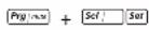
1 In case of digital controller, press the : and : keys for approximately 5 seconds until 0.0.0 is displayed.
In case of remote user interface, push once.
2 Enter the correct password by using the ▲※ and ※▼ keys. The password's value is 22.
3 Press the Sel key to confirm the password and to enter the menu, 5-P is displayed.
4 Press the key to consult the parameter settings (= S - P) . (L - P means consulting the parameter level, but this function is not used). The r^ -parameter group is displayed.
5 Press the ▲※ or ⚙▼ key to select the required parameter group.
6 Press the Sel key to enter the selected parameter group.
7 Press the ▲※ or ⚙▼ key to select the required parameter.
8 Press the Sol; key to consult the selected parameter.
9 Press the ▲※ or ⚫▼ key to increase, respectively decrease the setting. (Only valid for read/write parameters.)
10 Press the Sel key to confirm the modified setting. OR Press the Prg | n.s.h key to cancel the modified setting.
11 Press the Prg | n24 key to return to the parameter group.
12 Press 2 times the Prg issue key to return to the main display.
If during the procedure no buttons are pressed for 30 seconds, the displayed parameter code or value will start flashing. After another 30 seconds without pressing any buttons, the controller automatically returns to the main display without saving any modified parameter.
Defining the cooling temperature differential
Modify the r-02 cooling differential parameter.
This is a direct parameter, refer to "How to consult and modify the direct parameters" on page 7.
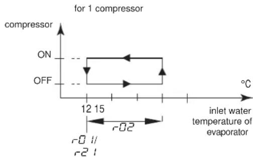
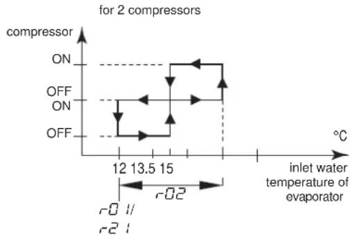
line
| inlet water temperature of evaporator | compressor | | ------------------------------------- | ---------- | | 12 | ON | | 13.5 | OFF | | 15 | ON | | 15 | OFF |Defining the heating temperature differential
Modify the -04 heating differential parameter.
This is a direct parameter, refer to "How to consult and modify the direct parameters" on page 7.
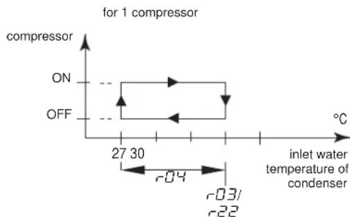
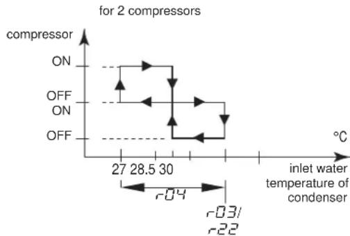
line
| inlet water temperature of condenser | compressor | | ------------------------------------ | ---------- | | 27 | ON | | 28.5 | OFF | | 30 | ON | | 30 | OFF |Tasks carried out using user parameters
Defining the measurement unit
Depending on the setting of user parameter r'23 (measurement unit), all temperature values are displayed in °C (=0) or in °F (=1).
This is a user parameter, refer to "How to consult and modify the user parameters" on page 10.
Defining the time delay between pump and compressor startup
User parameter c07 allows you to define the time delay between the pump startup and the compressor startup.
This is a user parameter, refer to "How to consult and modify the user parameters" on page 10.
Defining the time delay between unit and pump shutdown
User parameter c08 allows you to define the time delay between the unit shutdown and the pump shutdown, more specifically the period during which the pump will still be active after the unit has been shut down.
This is a user parameter, refer to "How to consult and modify the user parameters" on page 10.
Defining the timer threshold for maintenance warning
User parameter c = 14 allows you to define a timer threshold (running hours of the compressor) after which the controller will generate a maintenance warning or request.
This is a user parameter, refer to "How to consult and modify the user parameters" on page 10.
Selecting local or remote cool/heat control
User parameter H05 in combination with the remote cool/heat selection switch (installed by the customer) allows the user to select cooling or heating mode without using the □▼ or ▲▲ key on the controller.
■ When user parameter HOB is set to 0 (=not active), cooling or heating mode is determined by means of the controller.
■ When user parameter HOB is set to 1 (=active), cooling or heating mode is determined by means of the remote switch.
This is a user parameter, refer to "How to consult and modify the user parameters" on page 10.

This is only in case P09 (changeable digital input selection S7S) has value 9 (default value).
In case dual setpoint function is selected for this function (PQ9=13) then the remote cool/heat control is not activated. Meaning the ☐ or ▲ keys on the controller are still active.
Selecting local or remote on/off control
User parameter H07 in combination with the remote on/off switch (installed by the customer) allows the user to switch the unit on without using the ☑▼ or ▲▲ key on the controller.
■ When user parameter H07 is set to □ (=not active), the unit can only be switched on by means of the ☑ and ▲ key on the controller.
■ When user parameter H07 is set to 1 (=active), the unit can be switched on or off as follows:
■ When remote on/off switch is opened, then the unit is switched off and it is not possible to switch the unit on/off while pressing the ⚙▼ or ▲★ key on the controller (5 sec).
■ When remote on/off switch is closed, then the unit is switched on and it is possible to switch the unit on/off while pressing the ⚫▼ or ▲※ key on the controller (5 sec).
This is a user parameter, refer to "How to consult and modify the user parameters" on page 10.

■ This is only in case P34 (changeable digital input selection S9S) has value 23 (default value).
■ In case dual setpoint function is selected for this function (P34=13) then the remote on/off control is not activated.
Selecting dual setpoint control
User parameters P09 (changeable digital selection S7S) and P34 (changeable digital selection S9S) can be used to assign the dual setpoint control to S7S or S9S.
There are 3 different controls available for 2 different change digital inputs (S7S and S9S):
■ P09: changeable digital input selection S7S
■ 0=no function
■ 9=remote cool/heat
■ 13=remote dual setpoint
■ P34: changeable digital input selection S9S
■ 0=no function
■ 13=remote dual setpoint
■ 23=remote on/off
When dual setpoint switch is open, the first setpoint is activated (r01 cooling setpoint or r03 heating setpoint, depending on cooling or heating operation).
When dual setpoint switch is closed, the second setpoint is activated (r-2 / cooling setpoint 2 or r-2/2 heating setpoint 2, depending on cooling or heating operation).
This is a user parameter, refer to "How to consult and modify the user parameters" on page 10.
Locking the controller keyboard
Once user parameter H09 is set to 0, the following advanced features can no longer be carried out by means of the controller:
■ modifying direct and user parameters (parameters can be displayed but not modified),
■ resetting the timers.
■ switching the unit on/off in cooling or heating
When user parameter H09 is set to 1, the above-described advanced features can be carried out using the controller.
To modify user parameter H09 value from 1 to 0, the standard user parameter modification procedure can be used with the standard password "22". Refer to "How to consult and modify the user parameters" on page 10.
To modify user parameter H09 value from 0 to 1, the user parameter modification procedure can be used with dedicated password " / /". Refer to "How to consult and modify the user parameters" on page 10.
BMS CONNECTION MODBUS
By installing the optional kit address card EKAC10C, you will be able to communicate with your chiller through a Building Management System or supervisory system via the Modbus protocol.
General description of Modbus
The address card communicates using the Modbus protocol.
Different parts of the communication network
■ The communication network consists of two major players:
■ The Building Management System (BMS) or supervisory system.
■ The chiller or multiple chillers.
■ The BMS or other supervisory system is able to communicate with the chillers through the address card.
The management of the communication occurs in accordance with a master-slave structure in polling, where the supervising BMS is the master and the address cards are the slaves.
■ The chiller unit can be identified by the supervisor through the assignment of an address within the Modbus network. The address of the chiller unit can be programmed during the configuration of the BMS settings.
■ The variables database of every chiller with installed address card is the point of reference for the supplier of the supervisory system in Modbus to assign a suitable meaning to the variables. The variables can be read and/or written by the supervisory system. Whether the variables are read-only or read/write depends on the connected chiller and/or the application program being used.
- If the supervisory system assigns a value to a variable with read-only status, the command will not be executed at all.
- Variables requested by the supervisory system that are not available in a chiller with an address card are sent from the address card to the supervisory system with zero value. The supervisory system will have to manage these properly.
- In case the supervisory system tries to write a value of a parameter that is out of range, the writing will be ignored.
General information about the Modbus protocol
The Modicon Modbus protocol implemented in the address card complies with the content of the following document:
Modicon Modbus Protocol
Reference Guide
June 1996, PI-MBUS-300 Rev. J
The Modbus protocol implemented is of the RTU (Remote Terminal Unit) type based on character transmission times. The configuration uses the multi-drop feature of RS485. The address sent within the Modbus packet addresses the chiller unit.
Implemented RS485 communication settings for the Modbus protocol
The RS485 communication settings are implemented as follows:
■ Baud-rate: 9600
■ Stop bit: 2
■ Parity: none
Implemented commands for the Modbus protocol
The implemented commands in the program are as listed:
| Modbus command Meaning Notes | ||
| 01 read coil status | Read digital variable(s) | obtains current status (ON/OFF) of a group of logic coils or discrete input |
| 02 read input status | Read digital variable(s) | obtains current status (ON/OFF) of a group of logic coils or discrete input |
| 03 read holding registers | Read analogue variable(s) | obtains current binary value in one or more holding registers |
| 04 read input registers | Read analogue variable(s) | obtains current binary value in one or more holding registers |
| 05 force single coil | Write individual digital variable(s) | forces single coil to ON or OFF status |
| 06 preset single register | Write individual analogue variable(s) | places a specific binary value into a holding register |
| 15 force multiple coils | Write series of digital variables | forces a series of consecutive logic coils to be defined to ON or OFF status |
| 16 preset multiple registers | Write series of analogue variables | places specific binary values into a series of consecutive holding registers |
Note that:
■ Due to the variety of chillers with installed address cards, no distinction is made between input variables (with read-only status) and output variables (with read/write status) so that the knowledge of the database and its management depends on the part present on the supervisory system.
■ Due to the general nature of the system, the address card answers in the same way to various Modbus commands.
Data representation of the Modbus protocol
■ Digital
All digital data is coded by a single bit:
■ "0" for OFF
■ "1" for ON.
All digital variables are assigned to bits of consecutive registers, each one having:
■ the lower-address variable assigned to the less significant bit
■ the higher-address variable assigned to the most significant bit.
■ Analogue and integer data
An analogue and integer value is represented by a 16-bit WORD register in binary notation. For each register, the first byte contains the high order bits and the second byte contains the low order bits.
■ The analogue variables are represented in tenths:
for example, the value 10.0 is transmitted as 0064h=100d
for example, the value -10.0 is transmitted as FF9Ch=-100d
■ The integer variables are transferred using the effective value:
for example, the value 100 is transmitted as 0064h=100d
The address card operates on registers where one register must be considered at 16-bit.
In case the BMS or supervisory system tries to write a value of a parameter that is out of range, the writing will be ignored.
Implemented error code
Code Modbus interpretation Condition
| 1 Illegal function Message is not supported or thenumber of variables required is greaterthan the allowed limit (length ≤20) |
Defining the BMS setting
Activating the Modbus protocol
The Modbus protocol is activated by setting the H23 parameter to 1.
This is a user parameter, refer to "How to consult and modify the user parameters" on page 10.
Defining the unit's serial address
To define each unit's unique serial address required for communication with the supervisory system, set parameter H 10.
This is a user parameter, refer to "How to consult and modify the user parameters" on page 10.
Variables database
The BMS or supervisory system and the chiller unit communicate through a fixed set of variables, also called address numbers. Hereafter, you will find the information you need about the digital, integer and analogue variables that the BMS or supervisory system can read from or write to the address card of the chiller.
For addresses of all the direct and user parameters refer to "Overview of the direct and user parameters" on page 9.
Overview of all variables which are not direct or user parameters
| Description | Modbus address | Parameter type(a) | ||
| Circuit alarm | 1=A1, HP1, or LP1 alarm codes active0=no alarm code active | Read only | 41 | D |
| General alarm | 1=FL alarm code0=no alarm code active | Read only | 45 | D |
| NTC Probe alarm | 1=E1, E2, or E3 alarm codes0=no alarm code active | Read only | 46 | D |
| Input of flowswitch alarm | 1=closed0=open | Read only | 53 | D |
| Input of changeable digital S7S input | 1=closed0=open | Read only | 54 | D |
| Input of high pressure or discharge protector or overcurrent alarm | 1=closed0=open | Read only | 55 | D |
| Input of low pressure switch alarm | 1=closed0=open | Read only | 56 | D |
| Input of changeable digital S9S input | 1=closed0=open | Read only | 57 | D |
| Output of compressor 1 | 1=on0=off | Read only | 59 | D |
| Output of compressor 2 | 1=on0=off | Read only | 60 | D |
| Output of pump | 1=on0=off | Read only | 61 | D |
| Output of reversing valve | 1=on0=off | Read only | 62 | D |
| Output of alarm | 1=on0=off | Read only | 63 | D |
| On or off | 1=on0=off | Read/write | 64 | D |
| Cooling or heating | 1=cooling0=heating | Read/write | 65 | D |
(a) D=digital.
TROUBLESHOOTING
This section provides useful information for diagnosing and correcting certain troubles which may occur in the unit.
Before starting the trouble shooting procedure, carry out a thorough visual inspection of the unit and look for obvious defects such as loose connections or defective wiring.
Before contacting your local dealer, read this chapter carefully, it will save you time and money.

When carrying out an inspection on the supply panel or on the switch box of the unit, always make sure that the circuit breaker of the unit is switched off.
When a safety device was activated, stop the unit and find out why the safety device was activated before resetting it. Under no circumstances safety devices may be bridged or changed to a value other than the factory setting. If the cause of the problem cannot be found, call your local dealer.
Symptom 1: The unit does not start, but the LED lights up
| POSSIBLE CAUSES | CORRECTIVE ACTION |
| The temperature setting is not correct. | Check the controller setpoint. |
| Power supply failure. Check the voltage on the supply panel. | |
| Blown fuse or interrupted protection device. | Inspect fuses and protection devices. Replace by fuses of the same size and type (refer to chapter "Electrical specifications" on page 2). |
| Loose connections. Inspect connections of the field wiring and the internal wiring of the unit. Tighten all loose connections. | |
| Shorted or broken wires. Test circuits using a tester and repair if necessary. | |
Symptom 2: The unit does not start, but the LED is flashing
| POSSIBLE CAUSES | CORRECTIVE ACTION |
| The flowstart timer is still running. The | unit will start after approx. 15 seconds. Make sure that water is flowing through the evaporator. |
| The anti-recycling timer is still active. | The circuit can only start up after approximately 6 minutes. |
| The guard timer is still active. The circuit can only start up after approximately 1 minute. | |
Symptom 3: The unit does not start and the LED does not light up
| POSSIBLE CAUSES | CORRECTIVE ACTION |
| One of the following safety devices is activated:• R everse phase protector• O v ercurrent relay (K*S)• D ischarge thermal protector (Q*D)• E v aporating temperature thermostat (S*T)• F low switch (S10L)• H igh pressure switch (S*HP) | Check on the controller and refer to symptom "4. One of the following safety devices is activated". Refer to the explanation of the digital controller in the chapter "Resetting alarms" on page 8. |
| The unit is in anti-freeze alarm. Check | on the controller and refer to symptom "4. One of the following safety devices is activated". Refer to the explanation of the digital controller in the chapter "Resetting alarms" on page 8 |
| The remote ON/OFF input is enabled and the remote switch is off. | Put the remote switch on or disable the remote ON/OFF input. |
| The keyboard is locked. The user parameter HO9 is set to O. | Unlock the controller keyboard. |
Symptom 4: One of the following safety devices is activated
| Symptom 4.1: Overcurrent relay of compressor | |
| POSSIBLE CAUSES | CORRECTIVE ACTION |
| Failure of one of the phases. Check fuses on the supply panel or measure the supply voltage. | |
| Voltage too low. Measure the supply voltage. | |
| Overload of motor. | Reset. If the failure persists, call your local dealer. |
| RESET | Push the red button on the over-current relay inside the switch box.The controller still needs to be reset. |
| Symptom 4.2: Low pressure switch or anti-freeze alarm | |
| POSSIBLE CAUSES | CORRECTIVE ACTION |
| Water flow to water heat exchanger too low. | Increase the water flow. |
| Shortage of refrigerant. | Check for leaks and refill refrigerant, if necessary. |
| Unit is working out of its operation range. | Check the operation conditions of the unit. |
| Inlet temperature to the water heat exchanger is too low. | Increase the inlet water temperature. |
| Flow switch is not working or no water flow. | Check the flow switch and the water pump. |
| RESET | After pressure rise, the low pressure switch resets automatically, but the controller still needs to be reset. |
| Symptom 4.3: High-pressure switch | |
| POSSIBLE CAUSES | CORRECTIVE ACTION |
| Water flow through the condenser is too low. | Increase the water flow and/or check the strainer for clogging. |
| RESET | After pressure decrease, the high pressure switch resets automatically, but the controller still needs to be reset. |
| Symptom 4.4: Reverse phase protector is activated | |
| POSSIBLE CAUSES | CORRECTIVE ACTION |
| Two phases of the power supply are connected in the wrong phase position. | Invert two phases of the power supply (by licensed electrician). |
| One phase is not connected properly. | Check the connection of all phases. |
| RESET | After inverting two phases or fixing the power supply cables properly, the protector is reset automatically, but the unit still needs to be reset. |
| Symptom 4.5: Discharge thermal protector is activated | |
| POSSIBLE CAUSES | CORRECTIVE ACTION |
| Unit is working outside the operation range. | Check the operation condition of the unit. |
| RESET | After temperature decrease, the thermal protector resets automatically but the controller still needs to be reset. |
| Symptom 4.6: Flow switch is activated | |
| POSSIBLE CAUSES | CORRECTIVE ACTION |
| No water flow. | Check the water pump. |
| RESET | After finding the cause, the flow switch is reset automatically, but the controller still needs to be reset. |
Symptom 5: Unit stops soon after operation
| POSSIBLE CAUSES | CORRECTIVE ACTION |
| One of the safety devices is activated. | Check safety devices (refer to symptom "4. One of the following safety devices is activated"). |
| Voltage is too low. | Test the voltage in the supply panel and, if necessary, in the electrical compartment of the unit (voltage drop due to supply cables is too high). |
Symptom 6: Unit runs continuously and the water temperature remains higher than the temperature set on the controller
| POSSIBLE CAUSES | CORRECTIVE ACTION |
| The temperature setting on the controller is too low, respectively too high. | Check and adjust the temperature setting. |
| The heat production, respectively cold production in the water circuit is too high. | The cooling, respectively heating capacity of the unit is too low. Call your local dealer. |
| Water flow is too high. Recalculate the | water flow. |
Symptom 7: Excessive noises and vibrations of the unit
| POSSIBLE CAUSES | CORRECTIVE ACTION |
| Unit has not been fixed properly. Fix the unit as described in the installation manual. | |
MAINTENANCE
In order to ensure optimal availability of the unit, a number of checks and inspections on the unit and the field wiring have to be carried out at regular intervals.
If the unit is used for air conditioning application, the described checks should be executed at least once a year. In case the unit is used for other applications, the checks should be executed every 4 months.

Before carrying out any maintenance or repair activity, always switch off the circuit breaker on the supply panel, remove the fuses or open the protection devices of the unit.
Do never clean the unit with water under pressure.
Important information regarding the refrigerant used
This product contains fluorinated greenhouse gases covered by the Kyoto Protocol.
Refrigerant type: R410A
GWP ^(1) value: 2090
(1) GWP = global warming potential
Periodical inspections for refrigerant leaks may be required depending on European or local legislation. Please contact your local dealer for more information.
Maintenance activities

The wiring and power supply must be checked by a licensed electrician.
■ Field wiring and power supply
- Check the power supply voltage on the local supply panel. The voltage should correspond to the voltage marked on the identification label of the unit.
- Check the connections and make sure they are properly fixed.
- Check the proper operation of the circuit breaker and the earth leak detector provided on the local supply panel.
■ Internal wiring of the unit
Visually check the switch box on loose connections (terminals and components). Make sure that the electrical components are not damaged or loose.
■ Earth connection
Make sure that the earth wires are still connected properly and that the earth terminals are tightened.
■ Refrigerant circuit
- Check for leaks inside the unit. In case a leak is detected, call your local dealer.
- Check the working pressure of the unit. Refer to paragraph "Switching the unit on" on page 7.
■ Compressor
- Check on oil leaks. If there is an oil leak, call your local dealer.
- Check for abnormal noises and vibrations. If the compressor is damaged, call your local dealer.
■ Water supply
- Check if the water connection is still well fixed.
- Check the water quality (refer to the installation manual of the unit for specifications of the water quality).
■ Water filters
- Check if the mesh width is 1 mm maximum.
Disposal requirements
Dismantling of the unit, treatment of the refrigerant, of oil and of other parts must be done in accordance with relevant local and national legislation.
flowchart
graph TD
    A["Sensor readout menu (b0 1/b02/b03)"] --> B["*b03"]
    B --> C["2""]
    C --> D["*000"]
    D --> E["*b02"]
    E --> F["2""]
    F --> G["*000"]
    G --> H["*b01"]
    H --> I["2""]
    I --> J["*000"]
    J --> K["Prg_min"]
    K --> L["*88.8*"]
    L --> M["5'"]
    M --> N["*00"]
    N --> O["Select parameter setting values 5-P or levels L-P(a)"]
    O --> P["*5-P"]
    P --> Q["Prg_min"]
    Q --> R["*L-P"]
    R --> S["Select parameter group"]
    S --> T["*-b-"]
    T --> U["-R-"]
    U --> V["*-r-"]
    V --> W["Prg_min"]
    W --> X["Select parameter"]
    X --> Y["Select parameter"]
    Y --> Z["Prg_min"]
    Z --> AA["Read and modify parameter"]

    subgraph Parameter Sets
        AB["F-r"] --> AC["*-t-"]
        AC --> AD["*-r-"]
        AD --> AE["-P-"]
        AE --> AF["-H-"]
        AF --> AG["-F-"]
        AG --> AH["-d-"]
        AH --> AI["-c-"]
        AI --> AJ["*-b-"]
        AJ --> AK["-R-"]
        AK --> AL["*-r-"]
    end

    subgraph Parameters
        AM["r22"] --> AN["*-r22"]
        AN --> AO["*-r22"]
        AO --> AP["*-r22"]
        AP --> AQ["*-r22"]
        AQ --> AR["*-r22"]
        AR --> AS["*-r22"]
        AS --> AT["*-r22"]
        AT --> AU["*-r22"]
        AU --> AV["*-r22"]
        AV --> AW["*-r22"]
        AW --> AX["*-r22"]
        AX --> AY["*-r22"]
        AY --> AZ["*-r22"]
        AZ --> BA["*-r22"]
        BA --> BB["*-r22"]
        BB --> BC["*-r22"]
        BC --> BD["*-r22"]
        BD --> BE["*-r22"]
        BE --> BF["*-r22"]
        BF --> BG["*-r22"]
        BG --> BH["*-r22"]
        BH --> BI["*-r22"]
        BI --> BJ["*-r22"]
        BJ --> BK["*-r22"]
        BK --> BL["*-r22"]
        BL --> BM["*-r22"]
        BM --> BN["*-r22"]
        BN --> BO["*-r22"]
        BO --> BP["*-r22"]
        BP --> BQ["*-r22"]
        BQ --> BR["*-r22"]
        BR --> BS["*-r22"]
        BS --> BT["*-r22"]
        BT --> BU["*-r22"]
        BU --> BV["*-r22"]
        BV --> BW["*-r22"]
        BW --> BX["*-r22"]
        BX --> BY["*-r22"]
        BY --> BZ["*-r22"]
        BZ --> CA["*-r22"]
        CA --> CB["*-r22"]
        CB --> CC["*-r22"]
        CC --> CD["*-r22"]
        CD --> CE["*-r22"]
        CE --> CF["*-r22"]
        CF --> CG["*-r22"]
        CG --> CH["*-r22"]
        CH --> CI["*-r22"]
        CI --> CJ["*-r22"]
        CJ --> CK["*-r22"]
        CK --> CL["*-r22"]
        CL --> CM["*-r22"]
        CM --> CN["*-r22"]
        CN --> CO["*-r22"]
        CO --> CP["*-r22"]
        CP --> CQ["*-r22"]
        CQ --> CR["*-r22"]
        CR --> CS["*-r22"]
        CS --> CT["*-r22"]
        CT --> CU["*-r22"]
        CU --> CV["*-r22"]
        CV --> CW["*-r22"]
    end

    subgraph Parameters
        CX["Select parameter group"] --> CY["Select parameter"]
    end

    style Parameters fill:#f9f9f9,stroke:#333,stroke-width:1px
X1\~3,X1\~82A ..... Anschlüsse
line
| Wassertemperatur bei Eintritt in den Verdampfer | Value | |---|---| | 12 | r0 | | 13.5 | r2 | | 15 | r02 | | 15 | - | | 15 | - | | 15 | - | | 15 | - | | 15 | - | | 15 | - | | 15 | - | | 15 | - | | 15 | - | | 15 | - | | 15 | - | | 15 | - | | 15 | - | | 15 | - | | 15 | - | | | 15 | - | | 15 | - | | 15 | - | | 15 | - | | 15 | - | | 15 | - | | 15 | - | | 15 | - | | 15 | - | | 15 | - | | 15 | - | | 15 | - | | 15 | - | | 15 | - | | Note: The chart displays a single data series for 'EIN' and 'AUS' at specific temperature points. The values are estimated based on the 'Verdichter' axis, but they are not explicitly labeled in the image. The 'Wassertemperatur bei Eintritt in den Verdampfer' is indicated by the horizontal axis.(1) GWP = Treibhauspotential
flowchart
graph LR
    6 --> A["1"]
    9 --> B["2"]
    11 --> C["3"]
    10 --> D["4"]
    5 --> E["5"]
    1 --> F["6"]
    2 --> G["7"]
    1 --> H["8"]
    4 --> I["9"]
    3 --> J["10"]
    2 --> K["11"]
    1 --> L["9"]
    1 --> M["7"]
    style 5 fill:#f9f,stroke:#333
    style 4 fill:#ccf,stroke:#333
    style 3 fill:#cfc,stroke:#333
    style 2 fill:#fcc,stroke:#333
    style 1 fill:#cff,stroke:#333
    style 4 stroke:#333,stroke-width:2px
    style 3 stroke:#333,stroke-width:2px
    style 2 stroke:#333,stroke-width:2px
    style 1 stroke:#333,stroke-width:2px
    style 5 stroke:#fff,stroke-width:2px
    style 4 stroke:#fff,stroke-width:2px
    style 3 stroke:#fff,stroke-width:2px
    style 2 stroke:#fff,stroke-width:2px
    style 1 stroke:#fff,stroke-width:2px
    style 4 stroke:#fff,stroke-width:2px
    style 3 stroke:#fff,stroke-width:2px
    style 2 stroke:#fff,stroke-width:2px
    style 1 stroke:#fff,stroke-width:2px
    style 5 stroke:#fff,stroke-width:2px
EWWQ049\~064KB
flowchart
graph TD
    A["Input"] --> B["Valve 1"]
    B --> C["Valve 2"]
    C --> D["Valve 3"]
    D --> E["Valve 4"]
    E --> F["Valve 5"]
    F --> G["Valve 6"]
    G --> H["Valve 7"]
    H --> I["Valve 8"]
    I --> J["Valve 9"]
    J --> K["Valve 10"]
    K --> L["Valve 11"]
    L --> M["Valve 12"]
    M --> N["Valve 13"]
    N --> O["Valve 14"]
    O --> P["Valve 15"]
    P --> Q["Valve 16"]
    Q --> R["Valve 17"]
    R --> S["Valve 18"]
    S --> T["Valve 19"]
    T --> U["Valve 20"]
    U --> V["Valve 21"]
    V --> W["Valve 22"]
    W --> X["Valve 23"]
    X --> Y["Valve 24"]
    Y --> Z["Valve 25"]
    Z --> AA["Valve 26"]
    AA --> AB["Valve 27"]
    AB --> AC["Valve 28"]
    AC --> AD["Valve 29"]
    AD --> AE["Valve 30"]
    AE --> AF["Valve 31"]
    AF --> AG["Valve 32"]
    AG --> AH["Valve 33"]
    AH --> AI["Valve 34"]
    AI --> AJ["Valve 35"]
    AJ --> AK["Valve 36"]
    AK --> AL["Valve 37"]
    AL --> AM["Valve 38"]
    AM --> AN["Valve 39"]
    AN --> AO["Valve 40"]
    AO --> AP["Valve 41"]
    AP --> AQ["Valve 42"]
    AQ --> AR["Valve 43"]
    AR --> AS["Valve 44"]
    AS --> AT["Valve 45"]
    AT --> AU["Valve 46"]
    AU --> AV["Valve 47"]
    AV --> AW["Valve 48"]
    AW --> AX["Valve 49"]
    AX --> AY["Valve 50"]
    AY --> AZ["Valve 51"]
    AZ --> BA["Valve 52"]
    BA --> BB["Valve 53"]
    BB --> BC["Valve 54"]
    BC --> BD["Valve 55"]
    BD --> BE["Valve 56"]
    BE --> BF["Valve 57"]
    BF --> BG["Valve 58"]
    BG --> BH["Valve 59"]
    BH --> BI["Valve 60"]
    BI --> BJ["Valve 61"]
    BJ --> BK["Valve 62"]
    BK --> BL["Valve 63"]
    BL --> BM["Valve 64"]
    BM --> BN["Valve 65"]
    BN --> BO["Valve 66"]
    BO --> BP["Valve 67"]
    BP --> BQ["Valve 68"]
    BQ --> BR["Valve 69"]
    BR --> BS["Valve 70"]
    BS --> BT["Valve 71"]
    BT --> BU["Valve 72"]
    BU --> BV["Valve 73"]
    BV --> BW["Valve 74"]
    BW --> BX["Valve 75"]
    BX --> BY["Valve 76"]
    BY --> BZ["Valve 77"]
    BZ --> CA["Valve 78"]
    CA --> CB["Valve 79"]
    CB --> CC["Valve 80"]
K1M,K2M...... Compressorschakelaar circuit 1, circuit 2
K4S,K5S.... Overstroomrelais circuit 1, circuit 2
K6S...... * ...... Overstroomrelais pomp ^(2)
K1P.... * .... Pompschakelaar
M1C,M2C...... Compressormotor circuit 1, circuit 2
natural_image
Pure technical diagram of a rectangular enclosure with mounting holes and internal dashed lines indicating hidden edges (no text or symbols)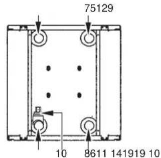
Figura - Componentes principales
1 Compresor
2 Evaporador
3 Condensador
4 Cuadro eléctrico
19 Interruptor principal
Figura - Controlador digital
Junio de 1996, PI-MBUS-300 Rev. J
natural_image
Pure technical diagram of a rectangular frame with internal components and arrows indicating direction (no text or symbols)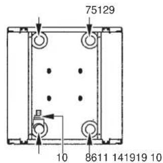
natural_image
Pure technical diagram of a mechanical or electrical component with no visible text, numbers, or symbols.
June 1996, PI-MBUS-300 Rev. J
natural_image
Pure technical diagram of a rectangular frame with bolt holes and internal dashed lines, no text or symbols present.
19 Interruptor principal
X1\~3,X1\~82A ...... Conectores
Figura - Controlador digital
line
para 2 compressores | Condition | Temperature (°C) | Trend Description | | :--- | :--- | :--- | | Ligado | 13.5 | Linear increase | | Desligado | 13.5 | Linear increase | | Desligado | 13.5 | Linear decrease | | Desligado | 13.5 | Linear decrease | | Desligado | 13.5 | Linear decrease | | Desligado | 13.5 | Linear decrease | | Desligado | 13.5 | Linear decrease | | Desligado | 13.5 | Linear decrease | | Desligado | 13.5 | Linear decrease | | Desligado | 13.5 | Linear decrease | | | Desligado | 13.5 | Linear decrease | | Desligado | 13.5 | Linear decrease | | Desligado | 13.5 | Linear decrease | | Desligado | 13.5 | Linear decrease | | Desligado | 13.5 | Linear decrease | | Desligado | 13.5 | Linear decrease | | Desligado | 13.5 | Linear decrease | | desligado | 13.5 | Linear decrease | | desligado | 13.5 | Linear decrease | | desligado | 13.5 | Linear decrease | | desligado | 13.5 | Linear decrease | | desligado | 13.5 | Linear decrease | | desligado | 13.5 | Linear decrease | | desligado | 13.5 | Linear decrease | | desligato | 13.5 | Linear decrease | | desligato | 13.5 | Linear decrease | | desligato | 13.5 | Linear decrease | | desligato | 13.5 | Linear decrease | | desligato | 13.5 | Linear decrease | | desligato | 13.5 | Linear decrease | | desligato | 13.5 | Linear decrease | | desligato | nan | -0.2, -0.2, -0.2, -0.2, -0.2, -0.2, -0.2, -0.2, -0.2, -0.2, -0.2, -0.2, -0.2, -0.2, -0.2, -0.2, -0.2, -0.2, -0.2, -0.2, -0.2 | | Temperatura da água de entrada do evaporadorComo definir o diferencial da temperatura de aquecimento
Modifique o parâmetro de diferencial de aquecimento r-04.
natural_image
Pure technical diagram of a rectangular frame with bolt holes and internal dashed lines, no text or symbols present.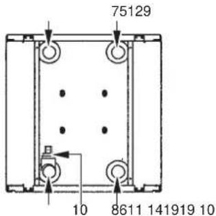

- Packaged water-cooled water chillers
- INTRODUCTION
- DESCRIPTION
- Function of the main components
- Safety devices
- Internal wiring - Parts table
- BEFORE OPERATION
- Checks before initial start-up
- Water supply
- General recommendations
- OPERATION
- Digital controller
- User interface
- Direct and user parameters
- Working with the units
- Switching the unit on
- Switching the unit off
- How to consult and modify the direct parameters
- How to consult the "sensor readout menu" parameters
- Adjusting the cooling temperature setpoint
- Adjusting the heating temperature setpoint
- Consulting actual operational information
- Resetting alarms
- Resetting warnings
- Advanced features of the digital controller
- Overview of the direct and user parameters
- How to consult and modify the user parameters
- Defining the cooling temperature differential
- Defining the heating temperature differential
- Tasks carried out using user parameters
- Defining the measurement unit
- Defining the time delay between pump and compressor startup
- Defining the time delay between unit and pump shutdown
- Defining the timer threshold for maintenance warning
- Selecting local or remote cool/heat control
- Selecting local or remote on/off control
- Selecting dual setpoint control
- Locking the controller keyboard
- BMS CONNECTION MODBUS
- General description of Modbus
- Different parts of the communication network
- General information about the Modbus protocol
- Implemented RS485 communication settings for the Modbus protocol
- Implemented commands for the Modbus protocol
- Note that:
- Data representation of the Modbus protocol
- ■ Digital
- ■ Analogue and integer data
- Implemented error code
- Defining the BMS setting
- Activating the Modbus protocol
- Defining the unit's serial address
- Variables database
- TROUBLESHOOTING
- MAINTENANCE
- Important information regarding the refrigerant used
- Maintenance activities
- Disposal requirements
- Como definir o diferencial da temperatura de aquecimento
Brand : DAIKIN
Model : EWWQ162KBW1N
Category : Air-conditioner