W10505928RP - Fridge KITCHENAID - Free user manual and instructions
Find the device manual for free W10505928RP KITCHENAID in PDF.

User questions about W10505928RP KITCHENAID
0 question about this device. Answer the ones you know or ask your own.
Ask a new question about this device
Download the instructions for your Fridge in PDF format for free! Find your manual W10505928RP - KITCHENAID and take your electronic device back in hand. On this page are published all the documents necessary for the use of your device. W10505928RP by KITCHENAID.
USER MANUAL W10505928RP KITCHENAID
text_image
Requesting Assist or Service...... Important Information...... Before youRequesting Assistance
or Service....2
Important
Information......3
Before you
Begin....4
Installing the
Ice Maker 5
Mounting the Ice Maker.....7
Connect the Water
Supply......10
Starting the
Ice Maker....13
Troubleshooting......14
Service Sheet ......15
Table of Contents
Page Page
Requesting Assistance or Service...... 2
Important Information 3
Before you Begin 4
Tools 4
Installation notes 4
Components 4
Installing the Ice Maker 5
Making preparations 5
Mounting the Ice Maker 7
Connect the Water Supply ....10
Connecting the power/ leveling the unit .....12
Starting the Ice Maker 13
Troubleshooting 14
Operational notes 14
Troubleshooting chart 14
Service Sheet 15
Specification 15
Service procedure 15
Requesting Assistance or Service
if you need assistance contact your dealer, or call the Whirlpool customer assistance centre toll-free, 1-800-253-1301, 24 hours a day.
Important Information
The following information is used throughout this installation Guide. Read it carefully so you are familiar with it.
Your safety and the safety of others are very important.
We have provided many important safety messages in this manual and on your appliance. Always read and obey all safety messages.

This is the safety alert symbol.
This symbol alerts you to potential hazards that can kill or hurt you and others.
All safety messages will follow the safety alert symbol and either the word "DANGER" or "WARNING."
These words mean:
! DANGER
You can be killed or seriously injured if you don't immediately follow instructions.
WARNING
You can be killed or seriously injured if you don't follow instructions.
All safety messages will tell you what the potential hazard is, tell you how to reduce the chance of injury, and tell you what can happen if the instructions are not followed.
- This Installation Guide gives you complete instructions on how to install the Ice Maker Kit in your ice maker-freezer and connect a water line to it. Please read the guide carefully and follow the instructions exactly as described. Also make sure that you observe all of the “safety” instructions.
- This kit is designed so that almost anyone can install it; however, a certain amount of mechanical ability is required.
CUSTOMER INSTALLATION IS NOT WARRANTED BY THE REFRIGERATOR OR ICE MAKER MANUFACTURER.
Before You Begin
Tools
Gather required tools and parts before starting installation. Read and follow the instructions provided with any tools listed here.
- Regular screwdriver
- Phillips screwdriver
- Pliers
- 1/4" nut driver
- Hand drill with 1/4" drill bit
- Small hand level (optional)
- Small 3/4" round file
- Tubing cutter
- Center punch
- Hammer
- Scissors
- Ruler
-
Step stool (optional)
-
7/16" and 1/2" open-end wrenches (or an adjustable wrench)
Components
Remove the contents from the shipping carton and set them on a table where they can be easily identified and located.
Do not discard any of the packing material until all required parts are identified.
Installation notes
For each set of steps shown, refer to the diagram immediately beside or below the text for clarification. Some illustrations also contain legends. Legends are labelled as A, B, or C and are clearly referenced in each step.
Install the parts as instructed in each step and corresponding illustration.
| QTY DESCRIPTION | |
| 1 Ice | Maker Top Mount (TM) |
| 1 Pan | Ice Cube |
| 1 | Wire shelveFreezer Compartment (FC) |
| 1 | Ice Maker Cover(on Bottom-Mount) |
| 1 Fill | Tube Extension TM |
| 1 Water | Fill Tube Bottom Mount (BM) |
| 3 7-18 | X .500 MHW TLR LSER |
| 1 Instruction | Booklet TM/BM (New) |
| 1 Warranty Letter (2206023) | |
Installing the Ice Maker
Making preparations
WARNING
Excessive Weight Hazard
Use two or more people to move and install ice maker.
Failure to do so can result in back or other injury.
- Pull the ice maker away from the wall so that you can easily access the rear panel.
Important : Make sure to protect the floor from any damage.
WARNING

Electrical Shock Hazard
Disconnect power before installing ice maker.
Failure to do so can result in death or electrical shock.
- Unplug ice maker on disconnect power.
-
Open the freezer door and remove all of the food items from the freezer compartment.
-
Ice maker connector and tube cover is located inside the freezer compartment.
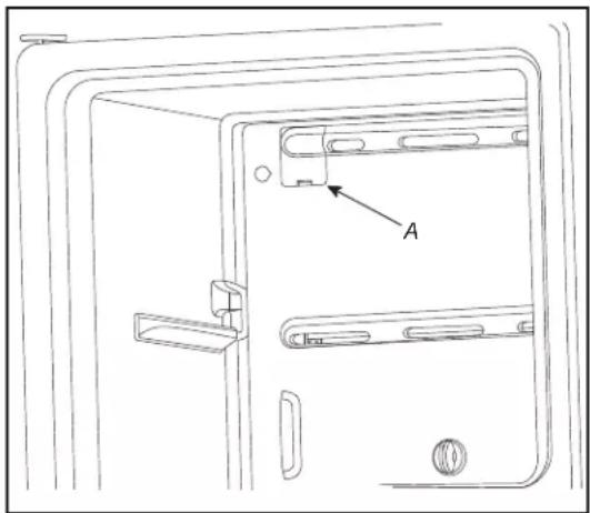
text_image
AA. Connector & tube cover
Top Mount models
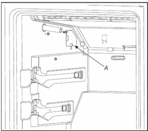
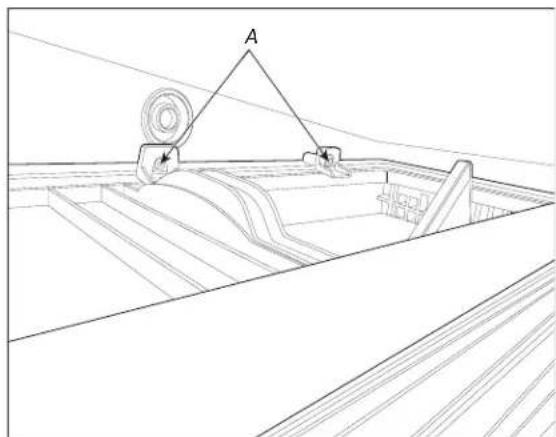
text_image
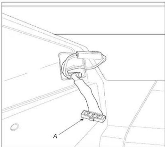
Technical diagram of a device interior with labeled component A and directional arrows indicating flow or movement.A. Connector
Bottom Mount models
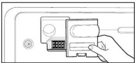
- Remove the ice maker connector and tube cover.
natural_image
Line drawing of a hand inserting a card into a device (no text or symbols visible)Top Mount models
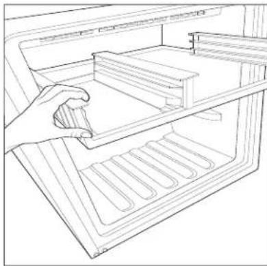
- Remove the shelf from freezer compartment. Ice maker connector is located on the left hand side as shown in the illustration..
natural_image
Line drawing of a hand placing a tray into an open refrigerator (no text or symbols)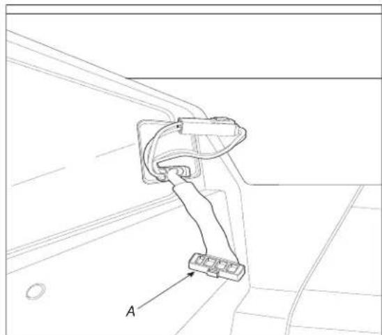
natural_image
Technical line drawing of a mechanical component with labeled section A (no text or symbols beyond label)A. Ice maker connector
Bottom Mount models
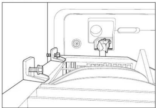
Mounting the Ice Maker
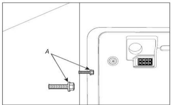
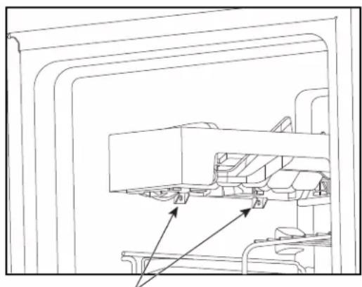
- Base screws are provided in freezer compartment to install the ice maker.
text_image
AA. Base Screws
Top Mount models
natural_image
Technical line drawing of a mechanical assembly with labeled component A (no text or symbols beyond label)A. Base Screws
Bottom Mount models
- Align the two holes on ice maker with the base screws. Hang the ice maker on the two base screws.
natural_image
Technical line drawing of a mechanical assembly or mounting bracket (no text or symbols)Top Mount models
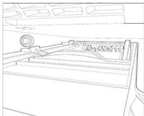
natural_image
Line drawing of a mechanical component or bracket with no visible text or symbolsBottom Mount models
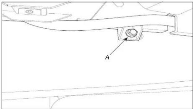
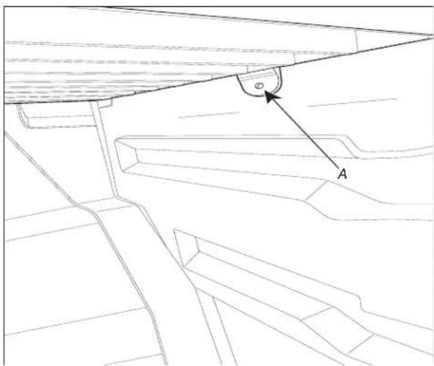
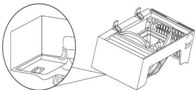
- Install the screw in bracket mounting hole as shown in the figure.
text_image
AA. Bracket mounting hole Top Mount models
-
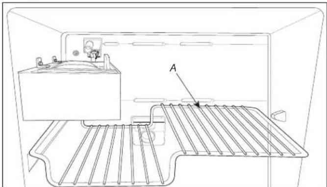
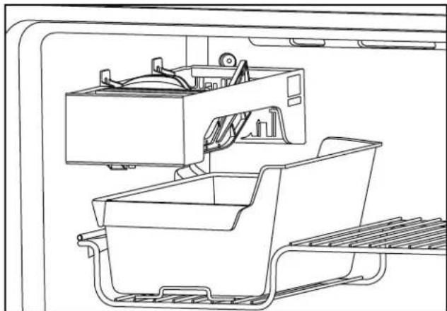
Install the wire shelf as shown in figure.
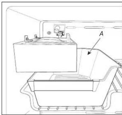
-
Install the ice maker pan as shown in the figure.
natural_image
Line drawing of a refrigerator interior with a rack and vent, no text or symbols presentA. Wire shelf
natural_image
Technical line drawing of a mechanical component with labeled point A (no text or symbols beyond label)A. Bracket mounting hole Bottom Mount models
natural_image
Technical line drawing of a battery mounted on a tray, with no visible text or symbolsA. Ice maker pan Top Mount models
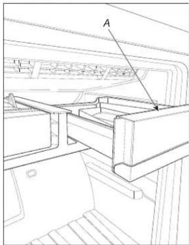
- Install the bin as shown in the figure.
text_image
AA. Ice maker bin
Bottom Mount models
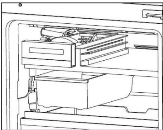
- Install the ice maker pan as shown in the figure.
NOTE: Check that ice maker pan is correctly located below the ice maker.
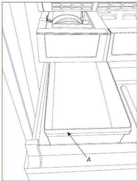
natural_image
Line drawing of a cabinet or rack system with labeled component 'A' (no text or symbols beyond label)A. Ice maker pan
Bottom Mount models
Connect the Water Supply
Read all directions before you begin.
IMPORTANT:
- Connect to potable water supply only.
Do not use with water that is microbiologically unsafe or of unknown quality without adequate disinfection before or after the system. Systems certified for cyst reduction may be used on disinfected waters that may contain filterable cysts.
- Plumbing must be installed in accordance with the International Plumbing Code and any local codes and ordinances.
- Copper and PEX tubing connections from the household water line to the refrigerator are acceptable and will help avoid off-taste or odor in your ice or water. Check for leaks.
- If PEX tubing is used instead of copper, we recommend the following part numbers: W10505928RP (7 ft [2.14 m] jacketed PEX), 8212547RP (5 ft [1.52 m] PEX), or W10267701RP (25 ft [7.62 m] PEX).
• Install tubing only in areas where temperatures will remain above freezing.
Tools Needed:
Gather the required tools and parts before starting installation.
- Flat-blade screwdriver
- 7/16" and 1/2" open-end wrenches or 2 adjustable wrenches
- 1/4" nut driver
NOTE: Do not use a piercing-type or 3/16" (4.76 mm) saddle valve, which reduces water flow and clogs easier.
Connect to Water Line
IMPORTANT: If you have turned the refrigerator on before the water was connected, turn off the ice maker.
- Unplug refrigerator or disconnect power.
- Turn off main water supply. Turn on nearest faucet long enough to reduce water pressure in the water line.
- Use a quarter-turn shut-off valve or the equivalent, served by a 1/2" household supply line.
NOTE: To allow sufficient water flow to the refrigerator, a minimum 1/2" (12.7 mm) size household supply line is recommended.
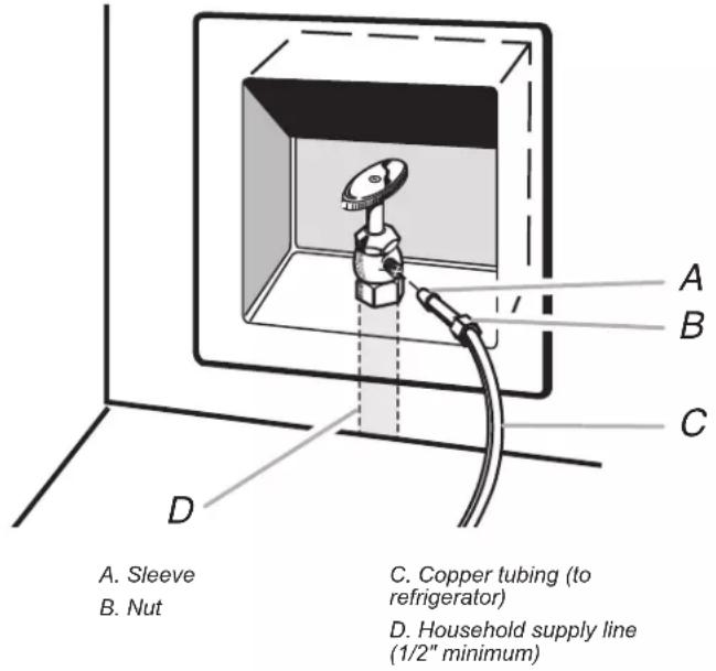
text_image
A. Sleeve B. Nut C. Copper tubing (to refrigerator) D. Household supply line (1/2" minimum)- Now you are ready to connect the copper tubing to the shut-off valve. Use 1/4" (6.35 mm) O.D. (outside diameter) soft copper tubing to connect the shut-off valve and the refrigerator.
- Ensure that you have the proper length needed for the job. Be sure both ends of the copper tubing are cut square.
- Slip compression sleeve and compression nut onto copper tubing as shown. Insert end of tubing into outlet end squarely as far as it will go. Screw compression nut onto outlet end with adjustable wrench. Do not overtighten.
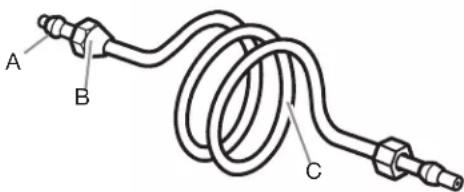
text_image
A B CA. Compression sleeve
B. Compression nut
C. Copper tubing
- Place the free end of the tubing into a container or sink and turn on main water supply to flush out tubing until water is clear. Turn off shut-off valve on the water pipe.
NOTE: Always drain the water line before making the final connection to the inlet of the water valve to avoid possible water valve malfunction.
- Bend the copper tubing to meet the water line inlet, located on the back of the refrigerator cabinet as shown. Leave a coil of copper tubing to allow the refrigerator to be pulled out of the cabinet or away from the wall for service.
Connect to Refrigerator
Follow the connection instructions specific to your model.
- Remove plastic cap from water valve inlet port. Attach the copper tubing to the valve inlet using a compression nut and sleeve as shown. Tighten the compression nut. Do not overtighten. Confirm copper tubing is secure by pulling on copper tubing.
- Create a service loop with the copper tubing. Avoid kinks when coiling the copper tubing. Secure copper tubing to refrigerator cabinet with a "P" clamp.
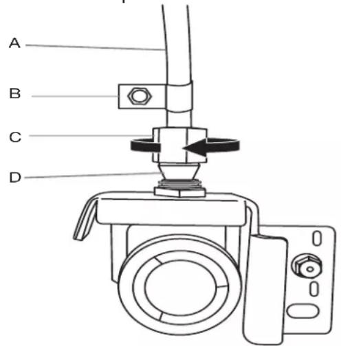
text_image
A B C DA. Copper tubing
C. Compression nut
B. "P" clamp
D. Compression sleeve
- Turn on water supply to refrigerator and check for leaks. Correct any leaks.
- If ice is desired, turn on the ice maker.
Complete the Installation
WARNING

Electrical Shock Hazard
Plug into a grounded 3 prong outlet.
Do not remove ground prong.
Do not use an adapter.
Do not use an extension cord.
Failure to follow these instructions can result in death, fire, or electrical shock.
- Plug into a grounded 3 prong outlet.
- Flush the water system. See the "Water and Ice Dispensers" section.
NOTE: Allow 24 hours to produce the first batch of ice. Discard the first 3 batches of ice produced. Allow 3 days to completely fill the ice storage bin.
Connecting the power/leveling the unit
WARNING

Electrical Shock Hazard
Plug into a grounded 3 prong outlet.
Do not remove ground prong.
Do not use an adapter.
Do not use an extension cord.
Failure to follow these instructions can result in death, fire, or electrical shock.
- Plug the power cord into its AC outlet, and push the ice maker back against the wall.
- Place a level on top of the cabinet. If you need to relevel the ice maker, follow the procedure to adjust the front casters, as outlined in your ice maker's "Use and Care Guide."
- Check the position of the ice maker. If it is crooked and needs to be adjusted, loosen the mounting screw and bracket screw (see the site diagram), position the ice maker as desired then tighten the screws.
natural_image
Technical line drawing of a mechanical assembly with no visible text or symbolsBracket mounting hole
Starting the Ice Maker
- Wash out the ice pan, and then slide it under the ice maker (see the side diagram) as far as it will go.
natural_image
Line drawing of an appliance interior showing front, side, and side views with no text or symbolsIMPORTANT: On bottom-mount models the Ice pan is placed below the ice maker and the multi utility shelf. The Ice maker should be screwed onto the multi utility shelf, so the Ice bucket must fit easily on the freezer compartment.
natural_image
Line drawing of an open refrigerator interior showing internal compartments and casing (no text or symbols)Top Mount & Bottom Mount models
- Place the items back into the freezer compartment.
- Turn the switch "on" (see the side diagram), and close the freezer door. The ice maker will begin to make ice within 24 hours.
NOTE: Usually it takes approximately 24 hours for the ice maker to begin producing ice. Once ice is available, you may notice that it has an "off-taste". If this happens, make two or three batches of ice and discard them. After that the "off-taste" should be gone. If you have any problem, refer to "Trouble shooting" on page 13.
natural_image
Technical line drawing of a mechanical device with an inset close-up showing internal components (no text or symbols)Troubleshooting
Operational notes
-
The Ice Maker valve contains a flow washer that acts like a pressure regulator to control the water flow. For the Ice Maker to work properly, the water pressure in your home must be between 20 and 120 pounds per-square-inch (psi). If you encounter problems with your Ice Maker's ability to produce ice, call your water utility company and have the water pressure checked.
-
The Ice Maker's water valve is equipped with two strainers: a plastic basket type and a wire-mesh screen. Both of these can be cleaned by turning off the water and disassembling the water valve (your service center should be able to provide this service). If local water conditions require periodic cleaning, or if you use a well as a water source, you should consider installing a second water strainer in the water line. You can obtain a water strainer from your local appliance dealer.
Troubleshooting chart
The following chart lists several common problems that could occur with your Ice Maker.
| PROBLEM CAUSE | |
| One or more of the following sounds is heard:BuzzingTrickling waterThud (clatter of ice) | The water valve is operating.Ice is being dumped into the ice bin. |
| Ice tastes stale. The ice is old. Make a new batch. | |
| Water in Ice Maker overflows. Refrigerator or Ice Maker | is not level. If the Ice Makerstill overflows after leveling, turn off the Ice Maker’swater supply at the shut-off valve and turn the switch“off”; then contact your local service center. |
| Not enough ice. It will take 48 hours to fill the ice bucket. | The icemaker will make ice every 2 to 3 hours. For more ice,adjust the freezer control for a colder setting |
| Ice making has stopped. Make sure that the water valve is Open.The water valve screen is clogged(contact your local service) |
ICE MAKER SERVICE SHEET
SPECIFICATIONS:
THERMISTOR INPUT TO CONTROL: - CLOSE -8.1°C(17.4°) OR AFTER 100 MIN
WATER FILL - 117 CC(m) 13.5 SEC.
CYCLE - ONE TWIST PROCESS
INPUT VOLTAGE: 120 & 240 V MODELS
NOTE: 24 HOURS ICE MAKER MAKE 56 TO 73 ICE CUBES
THE ICE MAKER REQUIRED 2-3 DAYS TO FILL THE ICE BIN CONTAINER.
(THE ICE MAKER REQUIRED 3 OURS TO ESTABILIZATION)
SERVICE PROCEDURE
MODULE MOTOR -
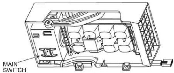
THE ON/OFF SWITCH (MAIN SWITCH) AND THE TEST SWITCH ARE LOCATED AT THE BOTTOM OF THE ICE MAKER.
MAIN SWITCH -
TURN THE MAIN SWITCH TO ON POSITION (AS SHOWN IN THE PICTURE BELOW), TO ENSURE ICE MAKER WILL WORK.
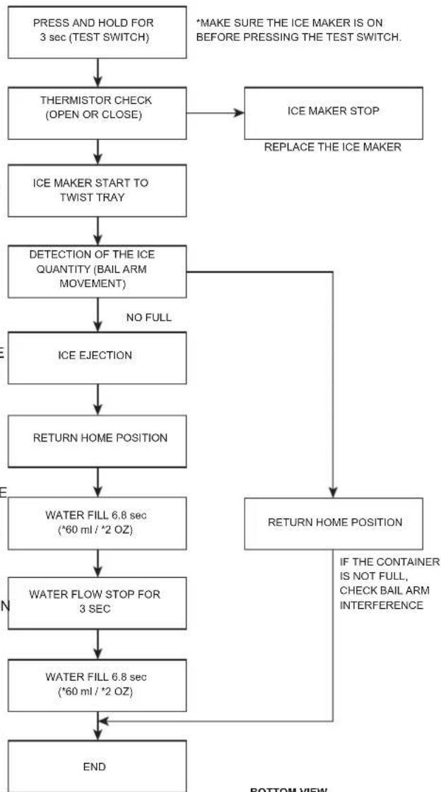
TEST SWITCH -
PRESS AND HOLD FOR 3 SECONDS; THE TEST SWITCH WILL BYPASS THE TIMER AND TEMPERATURE (THERMISTOR TEMPERATURE -8.1°C/17.4°F) AND WILL START TEST SEQUENCE
TEST SEQUENCE BELOW. MONITOR TEST FOR NORMAL CONDITIONS. IF TEST COMPLETES FULL CYCLE WITHOUT ABNORMAL CONDITION, ICE MAKER IS WORKING AND OPERATIONAL.
HOME POSITION -
THE ICE TRAY WILL MOVE TO HOME POSITION ONCE TURNED ON THE ICE MAKER OR AFTER A POWER RESET THEN STARTS THE TWIST PROCESS.
BAIL ARM -
AT THE SAME TIME AS THE TWIST PROCESS, THE BAIL ARM WILL GO DOWN TO DETECT THE ICE LEVEL.
WATER VALVE -
IF YOU DO NOT WANT TO PUT WATER DIRECTLY INTO THE TRAY, REMOVE FILL CHUTE AND CATCH WATER WITH A DISPOSABLE CUP.
THE VALVE WILL OPEN FOR 6.8 SECONDS TO DELIVERY A HALF AMOUNT OF WATER INTO THE TRAY. THE WATER FLOW WILL STOP FOR THE THREE SECONDS THEN THE VALVE WILL RE-OPEN FOR 6.8 SECONDS TO COMPLETE THE FILL(117ml). IF THE VALVE COMPLETES THE WATER FILL IN THE SPECIFIED VOLUME AND TIME, THE ICE MAKER IS WORKING AND IS FULLY OPERATIONAL.
NOTE: IF THE WATER VALVE OPERATES ONLY ONCE, IT MEANS
SOMETHING IN THE ICE MAKER IS WRONG (COULD BE BAIL ARM OR ICE MAKER MOTOR).
text_image
MAIN SWITCH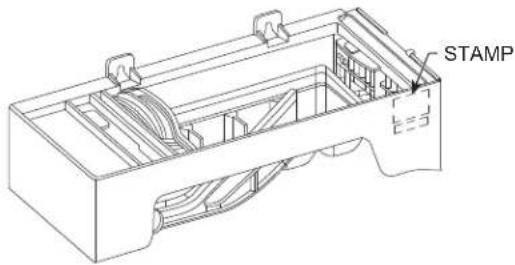
text_image
STAMP E=3THIS FLOW DIAGRAM IS ONLY FOR TEST SWITCH MODE
flowchart
graph TD
    A["PRESS AND HOLD FOR 3 sec (TEST SWITCH)"] --> B["THERMISTOR CHECK (OPEN OR CLOSE)"]
    B --> C["ICE MAKER START TO TWIST TRAY"]
    C --> D["DETECTION OF THE ICE QUANTITY (BAIL ARM MOVEMENT)"]
    D --> E["NO FULL ICE EJECTION"]
    E --> F["RETURN HOME POSITION"]
    F --> G["WATER FILL 6.8 sec (*60 ml / *2 OZ)"]
    G --> H["WATER FLOW STOP FOR 3 SEC"]
    H --> I["WATER FILL 6.8 sec (*60 ml / *2 OZ)"]
    I --> J["END"]
    K["*MAKE SURE THE ICE MAKER IS ON BEFORE PRESSING THE TEST SWITCH."] --> L["ICE MAKER STOP\nREPLACE THE ICE MAKER"]
    L --> M["RETURN HOME POSITION\nIF THE CONTAINER IS NOT FULL, CHECK BAIL ARM INTERFERENCE"]
    M --> N["BOTTOM VIEW"]

text_image
BOTTOM VIEW TEST SWITCH MAIN SWITCH - ON MAIN SWITCH - OFFWhirlpool®
D'installation
G U I D E

natural_image
Line drawing of a door frame with labeled component 'A' (no text or symbols beyond label)text_image
Technical diagram of a door panel with labeled component A and directional arrows indicating movement or assembly.natural_image
Line drawing of a hand inserting a card into a device (no text or symbols visible)natural_image
Line drawing of a hand placing a tray into an open refrigerator (no text or symbols)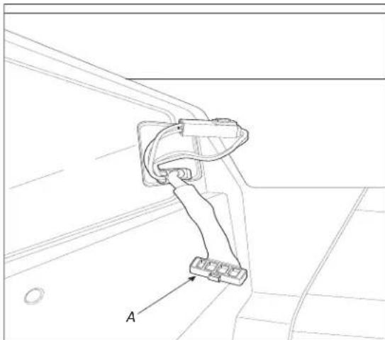
natural_image
Technical line drawing of a mechanical component with labeled section A (no text or symbols beyond label)natural_image
Technical line drawing of a mechanical assembly with labeled component A (no text or symbols beyond label)natural_image
Technical line drawing of a mechanical assembly or mounting bracket (no text or symbols)natural_image
Line drawing of a mechanical component or bracket assembly (no text or symbols)natural_image
Technical line drawing of a mechanical component with labeled points A and O (no text or symbols beyond labels)natural_image
Line drawing of a refrigerator interior with a rack and vent, labeled point A (no text or symbols beyond label)A. Clayette

natural_image
Technical line drawing of a battery mounted on a tray, with no visible text or symbolsnatural_image
Line drawing of a cabinet or rack system with labeled component 'A' (no text or symbols beyond label)A. Bac à glaçons
natural_image
Technical line drawing of a mechanical assembly with no visible text or symbolsnatural_image
Line drawing of an appliance interior showing front, side, and interior views (no text or symbols)natural_image
Line drawing of an open refrigerator interior showing internal compartments and casing (no text or symbols)natural_image
Technical line drawing of a mechanical device with an inset close-up showing internal components (no text or symbols)Dépannage
text_image
Technical diagram of a device interior with labeled component A and directional arrows indicating movement or flow.natural_image
Line drawing of a hand inserting a card into a device (no text or symbols visible)natural_image
Line drawing of a hand inserting a plastic into an open refrigerator drawer (no text or symbols)