
UP-TR1 - Wireless audio module ONKYO - Free user manual and instructions
Find the device manual for free UP-TR1 ONKYO in PDF.

| Product type | Wireless audio module |
| Brand | Onkyo |
| Model | UP-TR1 |
| Wireless technology | Rocketboost™ (uncompressed digital audio) |
| Dimensions (W × H × D) | 150 × 96 × 125.5 mm |
| Weight | 0.3 kg |
| Signal-to-noise ratio | 90 dB (LINE, IHF-A) |
| Power supply | Via tuner (connection cable included) |
| Power consumption in standby | Low (active standby mode) |
| Main functions | Wireless audio reception and transmission, network hub mode, pairing, source selection |
| Inputs | SUBWOOFER IN jack (RCA) |
| Connectors | Connection cable for tuner universal port |
| LED indicators | ON/STANDBY (blue/green), standby (red), source (blue), reception Rx (blue) |
| Buttons | ON/STANDBY, SOURCE |
| Compatibility | Onkyo TX-NRxx9 AV receivers and Rocketboost compatible models |
| Maintenance and cleaning | Wipe with a soft, dry cloth. Do not use solvents. |
| Safety | FCC Class B and NMB-003 Canada compliant. Do not use near water. |
| Operating temperature | Domestic use, avoid heat sources |
| Package contents | UP-TR1 module, connection cable, instruction manual |
| Repairability | Refer all repairs to qualified technician |
Frequently Asked Questions - UP-TR1 ONKYO
User questions about UP-TR1 ONKYO
0 question about this device. Answer the ones you know or ask your own.
Ask a new question about this device
Download the instructions for your Wireless audio module in PDF format for free! Find your manual UP-TR1 - ONKYO and take your electronic device back in hand. On this page are published all the documents necessary for the use of your device. UP-TR1 by ONKYO.
USER MANUAL UP-TR1 ONKYO
Important Safety Instructions
- Read these instructions.
- Keep these instructions.
- Heed all warnings.
- Follow all instructions.
- Do not use this apparatus near water.
- Clean only with dry cloth.
- Do not install near any heat sources such as radiators, heat registers, stoves, or other apparatus that produce heat.
- Unplug this apparatus during lightning storms or when unused for long periods of time.
-
Refer all servicing to qualified service personnel. Servicing is required when the apparatus has been damaged in any way, such as connection cord is damaged, liquid has been spilled or objects have fallen into the apparatus, the apparatus has been exposed to rain or moisture, does not operate normally, or has been dropped.
-
Damage Requiring Service
Unplug the apparatus from the AV receiver/amplifier and refer servicing to qualified service personnel under the following conditions:
A. If liquid has been spilled, or objects have fallen into the apparatus,
B. If the apparatus has been exposed to rain or water,
C. If the apparatus does not operate normally by following the operating instructions. Adjust only those controls that are covered by the operating instructions as an improper adjustment of other controls may result in damage and will
often require extensive work by a qualified technician to restore the apparatus to its normal operation,
D. If the apparatus has been dropped or damaged in any way, and
E. When the apparatus exhibits a distinct change in performance this indicates a need for service.
Precautions
- Care—Occasionally you should dust the unit all over with a soft cloth. For stubborn stains, use a soft cloth dampened with a weak solution of mild detergent and water. Dry the unit immediately afterwards with a clean cloth. Don't use abrasive cloths, thinners, alcohol, or other chemical solvents, because they may damage the finish or remove the panel lettering.
- Never Touch this Unit with Wet Hands—Never handle this unit while your hands are wet or damp. If water or any other liquid gets inside this unit, have it checked by your Onkyo dealer.
Legal notices
FCC Part 15
This device complies with Part 15 of the FCC Rules. Operation of this product is subject to the following two conditions: (1) this device may not cause harmful interference, and (2) this device must accept any interference received, including interference that may cause undesired operation.
This equipment has been tested and found to comply within the limits for a class B digital device, pursuant to Part 15 of the FCC Rules.
These limits are designed to provide reasonable protection against harmful interference in a residential installation. This equipment generates, uses, and can radiate radio frequency energy and, if not installed and used in accordance with the instructions, may cause harmful interference to radio communications. However, there is no guarantee that interference will not occur in a particular installation. If this equipment does cause harmful interference to radio or television reception, which can be determined by turning the equipment off and on, the user is encouraged to try to correct the interference by one or more of the following measures:
- Reorient or relocate the receiving antenna.
- Increase the separation between the equipment and receiver.
- Connect the equipment into an outlet on a circuit different from that to which the receiver is connected.
- Consult the dealer or an experienced technician for help.
FCC warning
Per FCC regulation 47 CFR 15.21: Changes or modifications not expressly approved by the party responsible for compliance with the FCC Rules could void the user's authority to operate this equipment.
Canada ICES-003 statement
This Class B digital apparatus complies with Canadian ICES-003.
Compatible models:
UP-TR1 can be used with the Onkyo TX-NRxx9 models and newly released Onkyo AV receiver models.
Please check the Onkyo web site for the details.
Top panel - UP-TR1
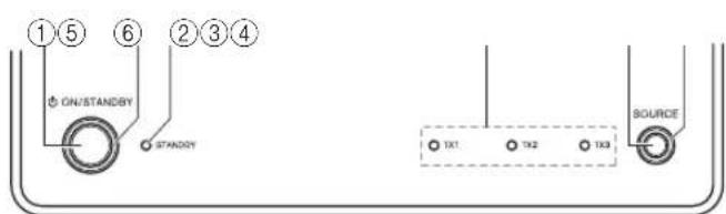
① ON/STANDBY button
Press to turn the device on, then hold to initiate pairing. Press again to go to standby.
②ON/STANDBY indicator
Lights blue when HUB STATUS is set to DISABLE.
Lights green when HUB STATUS is set to ENABLE.
Lights steady when the sender/receiver is paired to a network. Blinks slowly when the sender/receiver is not paired to a network. Blinks quickly when the sender/receiver is in pairing mode.
③Standby indicator
Lights red when the sender/receiver is in standby mode.
④TX1, TX2, TX3 sending mode indicators
Lights blue when the sender setup is ON. The indicator that lights and the receiver's display show the following.
| indicator | Receiver's indicator Explanation | |
| TX1 | TX1(ZONE2) Zone 2 channels are output | |
| TX1(FRONT) Front channels are output | ||
| TX2 | TX2(SB/FH) | Surround Back or Front High channels are output |
| TX2(SURRBK) SurBack channels are output | ||
| TX2(SURR) Surround channels are output | ||
| TX2() No sound is output | ||
| indicator | Receiver's indicator Explanation | |
| TX3 TX3(SUBW) | Subwoofer channel connected to the rear panel SUBWOOFER OUT jack is output | |
⑤SOURCE button
Press to move to the next receiving source. Each press toggles to the next source.
⑥Rx - Receiver mode indicator
Lights blue when receiving signals.
Back panel - UP-TR1
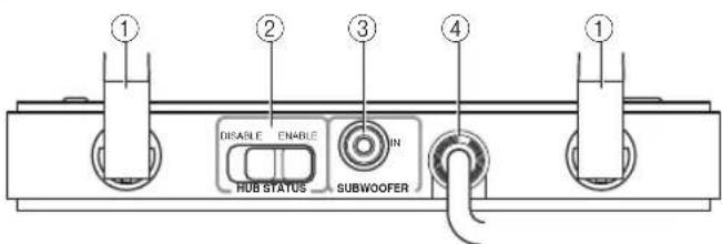
①External antenna
Receives signals from other Rocketboost™ senders. Sends signals to other Rocketboost™ receivers.
②HUB STATUS switch
Enables/disables hub mode operation. See "Establishing communications" for additional information.
When hub status is enabled, the device is on even when the receiver is in standby mode.
When hub status is disabled, the device is off when the receiver is in standby mode.
Note: In a Rocketboost™ network, only one Rocketboost™ device should have the Hub Status switch set to ENABLE.
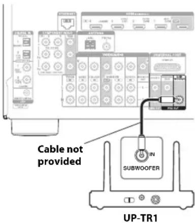
③SUBWOOFER IN jack
Connect to the SUBWOOFER PREOUT jack on the receiver using a mono RCA cable (not provided).
④Connection cable
Connect to the Universal Port on the receiver. The receiver supplies power, surround L/R, and Zone2 signals. The device supplies received signals from other Rocketboost™ senders.
What is Rocketboost™?
Rocketboost™ is expandable wireless digital audio.
- Products with Rocketboost™ technology let you easily expand your listening experience throughout your home.
- Rocketboost™ does not interfere with other wireless products in your home.
- Rocketboost™ is uncompressed digital audio compatible with all audio formats like Dolby TrueHD and DTS-HD Master Audio used with Blu-ray.

When you see the Rocketboost™ logo on any product, it has been designed to work with other Rocketboost™ products, no matter who manufactures them.
How can I use Rocketboost™ with the Onkyo Receiver?
The UP-TR1 can be used to receive any Rocketboost™ audio stream from your other Rocketboost™ products. For example, you can play music from audio sources that are in other rooms.
Plus, the UP-TR1 can be used to send audio from the receiver. For example, you can connect your rear surround sound speakers, or even subwoofer, by using Rocketboost™ wireless instead of wires.
You can also send Zone 2 audio from the receiver to other rooms in your house. For these applications you will need additional Rocketboost™ products. You can learn more about Rocketboost™ products at www.rocketboost.com.
Initial Rocketboost™ setup
Connect the connection cable to the Rocketboost™ Port on the back of the receiver.
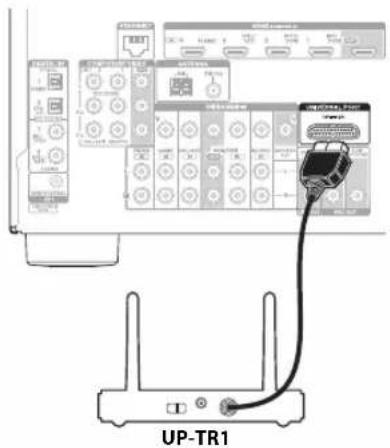
Adjust the antennas on the UP-TR1 as shown in the diagram.
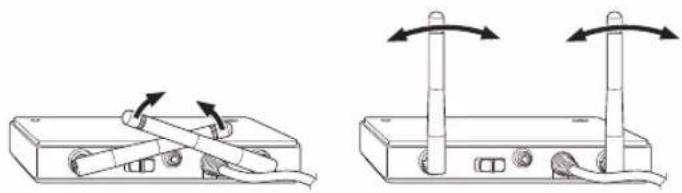
natural_image
Two technical diagrams showing mechanical components with arrows indicating rotation or movement (no text or symbols present)If you are using Rocket-boost™ to wirelessly send the audio signal to a subwoofer, then connect a subwoofer cable from the receiver subwoofer pre-out jack to the UP-TR1 SUBWOOFER IN jack. If you are not using Rocket-boost™ with a subwoofer then this connection should not be made.
Establishing communications
Note: Every Rocketboost™ network must contain a device called a Hub, which directs network data traffic and helps devices pair the network. The network can have only one hub, which is selected using the Hub Status switch on the back of all Rocketboost™ senders. If you are setting up your network for the first time choose one of your Rocketboost™ senders to be your hub by setting the Hub Status switch to Enable. If you already have a Rocketboost™ network, then set the Hub Status switch on the UP-TR1 to disable. The Status LED lights green for the Rocketboost™ Hub device, and lights blue for all other Rocketboost™ devices.
To establish communications:
- Press the ON/STANDBY button on the UP-TR1 to turn it on.
-
Set the HUB STATUS switch to ENABLE if the UP-TR1 is to be used as the network hub, otherwise set to DISABLE.
-
The ON/STANDBY indicator lights green when the HUB STATUS switch is set to ENABLE.
- The ON/STANDBY indicator lights blue when the HUB STATUS switch is set to DISABLE.
Note: When the HUB STATUS is set to ENABLE, power remains on when your receiver is off. When the HUB STATUS is set to DISABLE, the power will be off when your receiver is off.
- Press and hold the ON/STANDBY button on the UP-TR1 for more than three seconds to put it into pairing mode (it will remain in pairing mode for 30 seconds). The ON/STANDBY indicator LED starts blinking rapidly.
- Press the ON/STANDBY button on the sender/receiver device (the one configured as the hub) for more than three seconds, so the sender and receiver will enter pairing mode.
- When connected, the ON/STANDBY indicator on both pairing device and the hub will go solid, indicating the device is now connected to the network.
- The ON/STANDBY indicator lights steadily if the link is activated between both of the units.
- The ON/STANDBY indicator blinks at a slower rate if the communication link is not successful.
Setting up the Sender
Note: This is only required if you are using Rocketboost™ for your Zone2, Surround, or Subwoofer audio.
To set up the Sender:
- Press the ON/STANDBY button on the UP-TR1 to turn it on.
- Press the PORT input selector on the receiver's remote control.
-
Press SETUP on the remote control to enter the Source Setup menu for the UP-TR1.
-
Press ▼ or ▲ to select Sender Setup, then press ENTER.
-
Press or to select the Sender you want (TX1(****), TX2(****), TX3(****)), then press ENTER.
- Press or to turn the selected Sender ON or OFF, then press ENTER.
Note: Set the Sender signals to OFF for any signals (Zone2, Surround, or Subwoofer) that you are not using.
Listening to music from other Rocketboost™ products
To listen to music:
- Press the ON/STANDBY button on the UP-TR1 to turn it on.
- Press the PORT input selector on the receiver's remote control.
- Turn on your other Rocketboost™ sender device (sold separately) and make sure the audio source connected to that device is active.
- The Rx indicator should be lit if a source is active on the network. If not, check to make sure there is an active source.
- If there are multiple sources, you may need to press the SOURCE button on the UP-TR1 to find the source you wish to listen to. Each press will toggle through the available sources.
- You can also select the Rocketboost™ source using the UP-TR1 Source Setup menu. To do this, press PORT, and then SETUP on the remote control to enter the menu. Then press or to select the Source you want to listen to and press the ENTER button to select it.
Going into standby mode
To go to standby mode:
- Press the ON/STANDBY button and the STANDBY indicator will light, indicating the device is in sleep mode.
WIRELESS Problems
If you don't hear any sound or if the audio is not synchronized, check the following. This may solve the problem.
- Set the receiver's Speaker Configuration "Wireless" setting to "Yes".
- Enable hub mode on the UP-TR1.
No communication between the UP-TR1 and your receiver
- Make sure that Hub Status switch on the UP-TR1 is set correctly.
- Make sure that the ON/STANDBY indicator on UP-TR1 and other devices light solid blue/green. If the ON/STANDBY indicator blinks slowly, try to establish the link again. For more information, see "Establishing communications".
Cannot connect a source device
- If your network is already full with transmitters when pairing is attempted, the source LED will blink three times and then turn off. Remove (power down) a transmitting device and try again.
- When you try to pair a device to a network that has too many nodes, the device will stay in pairing mode until it times out (30 second timeout). Upon timeout the unit should be on and flash the ON/STANDBY indicator in a slow blink indicating it is not connected to the network.
Specifications
Note: Design and specifications are subject to change without notice.
Wireless
Signal to Noise ratio: 90 dB (LINE, IHF-A) Dimension (W×H×D): 150×96×125.5 mm (5-7/8"×3-3/4"×4-15/16") Weight: 0.3 kg (0.7 lbs.)
①Antenne externe
natural_image
Two technical diagrams showing a device with two vertical posts and cable connections, no text or symbols present.Etablir les communications
①Antena externa
natural_image
Two diagrams showing a device with cable and switch connections, no text or symbols present18 Park Way, Upper Saddle River, N.J. 07458, U.S.A.
Tel: 800-229-1687, 201-785-2600 Fax: 201-785-2650
http://www.us.onkyo.com/
ONKYO EUROPE ELECTRONICS GmbH
Liegnitzerstrasse 6, 82194 Groebenzell, GERMANY
Tel: +49-8142-4401-0 Fax: +49-8142-4401-555
http://www.eu.onkyo.com/
ONKYO EUROPE ELECTRONICS GmbH (UK BRANCH)
The Coach House 81A High Street, Marlow, Buckinghamshire, SL7 1AB, UK
Tel: +44-(0)1628-473-350 Fax: +44-(0)1628-401-700
ONKYO CHINA LIMITED
Unit 1033, 10/F, Star House, No 3, Salisbury Road, Tsim Sha Tsui Kowloon, Hong Kong.
Tel: 852-2429-3118 Fax: 852-2428-9039
http://www.ch.onkyo.com/
ONKYO CHINA PRC
1301, 555 Tower, No.555 West NanJin Road, Jin an, Shanghai,
China 200041, Tel: 86-21-52131366 Fax: 86-21-52130396
I1106-2
SN 29400832A
(C) Copyright 2011 ONKYO SOUND & VISION CORPORATION Japan. All rights reserved.

- Important Safety Instructions
- Precautions
- Legal notices
- FCC Part 15
- FCC warning
- Canada ICES-003 statement
- Compatible models:
- Top panel - UP-TR1
- ① ON/STANDBY button
- ②ON/STANDBY indicator
- ③Standby indicator
- ④TX1, TX2, TX3 sending mode indicators
- ⑤SOURCE button
- ⑥Rx - Receiver mode indicator
- Back panel - UP-TR1
- ①External antenna
- ②HUB STATUS switch
- ③SUBWOOFER IN jack
- ④Connection cable
- What is Rocketboost™?
- How can I use Rocketboost™ with the Onkyo Receiver?
- Initial Rocketboost™ setup
- Establishing communications
- To establish communications:
- Setting up the Sender
- To set up the Sender:
- Listening to music from other Rocketboost™ products
- To listen to music:
- Going into standby mode
- To go to standby mode:
- WIRELESS Problems
- If you don't hear any sound or if the audio is not synchronized, check the following. This may solve the problem.
- No communication between the UP-TR1 and your receiver
- Cannot connect a source device
- Specifications
- Wireless
- ①Antenne externe
- Etablir les communications
- ①Antena externa
- ONKYO EUROPE ELECTRONICS GmbH
- ONKYO EUROPE ELECTRONICS GmbH (UK BRANCH)
- ONKYO CHINA LIMITED
- ONKYO CHINA PRC
Brand : ONKYO
Model : UP-TR1
Category : Wireless audio module