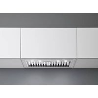
Gruppo Incasso Pro - Basket FALMEC - Free user manual and instructions
Find the device manual for free Gruppo Incasso Pro FALMEC in PDF.


User questions about Gruppo Incasso Pro FALMEC
0 question about this device. Answer the ones you know or ask your own.
Ask a new question about this device
Download the instructions for your Basket in PDF format for free! Find your manual Gruppo Incasso Pro - FALMEC and take your electronic device back in hand. On this page are published all the documents necessary for the use of your device. Gruppo Incasso Pro by FALMEC.
USER MANUAL Gruppo Incasso Pro FALMEC
natural_image
Exterior view of a white ceiling-mounted air conditioner unit with multiple black connectors (no text or symbols visible)Professional
Gruppo Incasso Pro
INSTRUCTIONS BOOKLET
LIBRETTO ISTRUZIONI ^1T
INSTRUCTIONS BOOKLET EN
natural_image
Line drawing of a rectangular electronic device with a central circular component and wiring (no text or symbols)IT - MISURE FORO PER INCASSO
UK - HOLE MEASUREMENTS FOR INSTALLATION
NO-HULLMÅL FOR INNFELLING
natural_image
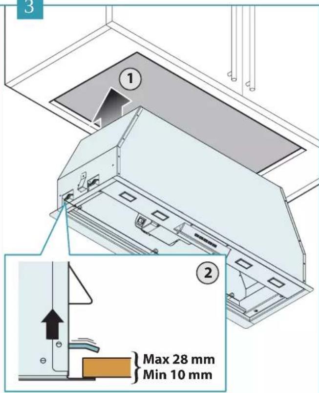
Illustration of various hand tools including a ladder, saw, gloves, and a hard hat (no text or symbols)IT - misure per l'installazione (1), foratura pensile (2), inserimento cappa (3). Fissaggio al pensile (4).
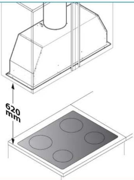
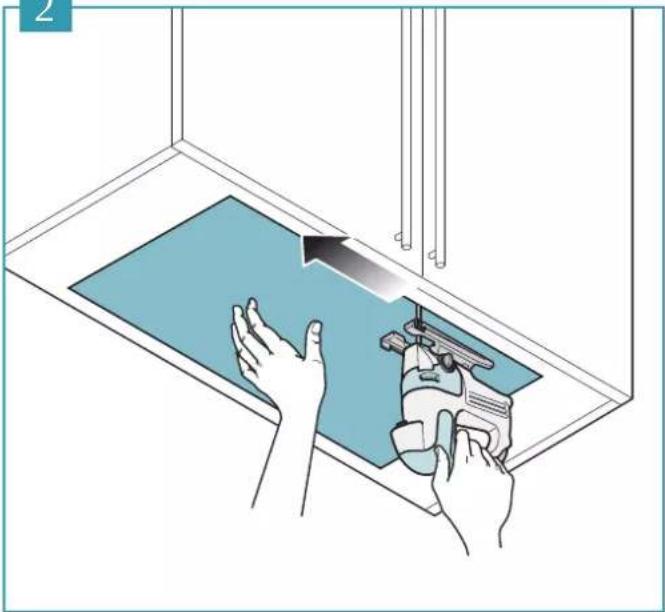
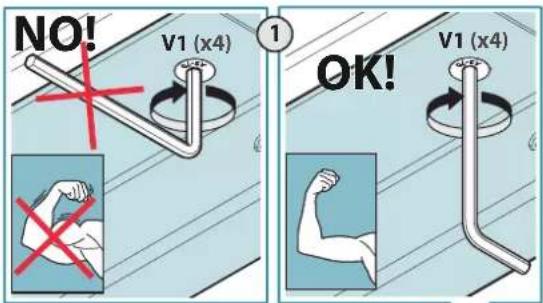
EN - measurements for installation (1), wall unit holes (2), hood installation (3). Fitting to the wall unit (4).
DE - Abmessungen für die Installation (1), Bohren des Hängeschranks (2), Einfügen der Abzugshaube (3). Befestigung am Hängekasten (4).
FR - mesures pour l'installation (1), perçage du meuble (2), mise en place de la hotte (3). Fixation au meuble (4).
ES - medidas para la instalación (1), orificio armario de pared (2), introducción campana (3). Fijación en el armario de pared (4).
RU - монтажные размеры (1), выполнение отверстия в навесном шкафу (2), монтаж вытяжки (3). Крепление к навесному шкафу (4).
PL - wymiary instalacji (1), nawiercenie szafki wiszącej (2), wsunięcie okapu (3). Mocowanie do szafki wiszącej (4).
NL - maten voor de installatie (1), boring keukenkastje (2), plaatsing kap (3). Bevestig- ging aan het keukenkastje (4).
PT - medidas para a instalação (1), furação do elemento suspenso (2), inserção da coifa (3). Fixação ao elemento suspenso (4).
DK - Installationsmål (1), hul i skab (2), Isætning af emhætten (3). Fastgørelse til skab (4).
SE - Mätt för installationen (1), hål i skåp (2), insättning av kåpa (3). Fastsättning i skåpet (4).
FI - asennusmitat (1), hyllyn aukon teko (2), liesituulettimen paikalleen asetus (3). Kiinnitys hyllyyn (4).
NO - installasjonsmål (1), boring i veggskap (2), innsetting av ventilatorhette (3). Festing til veggskap (4).
1
text_image
620 mm2
natural_image
Illustration of hands using a tool to clean or repair a blue surface, no text or symbols present3
text_image
3 ① ② Max 28 mm Min 10 mm4
text_image
NO! V1 (x4) ① OK! V1 (x4)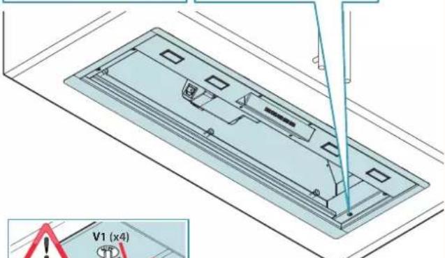
text_image
V1 (x4)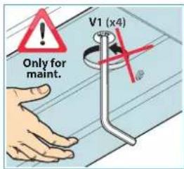
text_image
Only for maint. V1 (x4)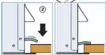
text_image
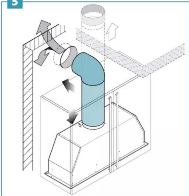
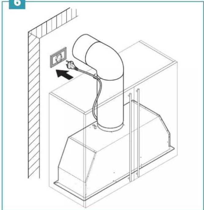
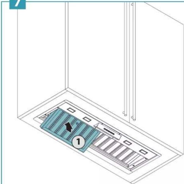
Diagram showing two mechanical or structural states with a downward arrow and numbered label (②), likely illustrating a process or assembly.IT - Montaggio tubo d'aspirazione (5), collegamento elettrico (6), montaggio filtri metallici (7).
EN - Assembling the suction pipe (5), electrical connection (6), assembling the metal filters (7).
DE - Montage der Ansaugleitung (5), elektrischer Anschluss (6), Montage der Metallfilter (7).
FR - Montage du tuyau d'aspiration (5), branchement électrique (6), montage des filtres métalliques (7).
ES - Montaje tubo de aspiración (5), conexión eléctrica (6), montaje de los filtros metálicos (7).
RU - Монтаж вытяжной трубы (5), подключение к сети электропитания (6), монтаж металлических фильтров (7).
PL - Montaż przewodu zasysającego (5), podłączenie elektryczne (6), montaż metalowych filtrów (7).
NL - Montage afzuigbuis (5), elektrische verbinding (6), montage metalen filters (7).
PT - Montagem da tubo de aspiração (5), ligação elétrica (6), montagem dos filtros metálicos (7).
DK - Montage af rør til udsug (5), elektrisk tilslutning (6), montage af metalfiltre (7).
SE - Montering och utsugningsrör (5), elektrisk anslutning (6), montering av metallfilter (7).
FI - Kehyksen imuputki (5), sähköliitäntä (6), metallisuodattimien asennus (7).
NO - Montering av innsugingsrør (5), elektrisk tilkobling (6), montering av metallfiltre (7).
5
natural_image
Technical diagram of a piping system with airflow indicators and structural components (no text or labels)6
natural_image
Technical line drawing of a mechanical device with an electrical outlet and wiring, no text or symbols present7
text_image
Technical diagram showing a component inside a ventilation duct with labeled parts and directional arrow2
3
natural_image
Illustration of a blue striped rectangular object with an arrow pointing to it, surrounded by faint geometric lines (no text or symbols)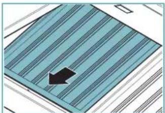
natural_image
Abstract 3D diagram with diagonal striped pattern and a black arrow pointing to a specific area (no text or symbols)text_image
Diagram showing two electrical setups with labeled components: one with a lever and handle, the other with a 12V power connection.VASCHETTA RACCOGLI OLIO
text_image
Diagram illustrating cleaning steps of a washing machine, showing hand cleaning and three labeled steps with arrows.SAFETY INSTRUCTIONS AND WARNINGS

Installation operations are to be carried out by skilled and qualified installers in accordance with the instructions in this booklet and in compliance with the regulations in force.
DO NOT use the hood if the power supply cable or other components are damaged: disconnect the hood from the electrical power supply and contact the Dealer or an authorised Servicing Dealer for repairs.
Do not modify the electrical, mechanical or functional structure of the equipment.
Do not personally try to carry out repairs or replacements. Interventions carried out by incompetent and unauthorised persons can cause serious damage to the unit or physical and personal harm, not covered by the Manufacturer's warranty.
WARNINGS FOR THE INSTALLER
TECHNICAL SAFETY

Before installing the hood, check the integrity and function of each part. Should anomalies be noted, do not proceed with ation and contact the Dealer.
Do NOT install the hood if an aesthetic (or cosmetic) defect has been detected. Put it back into its original package and contact the dealer.
No claim can be made for aesthetic (or cosmetic) defects once it has been installed.
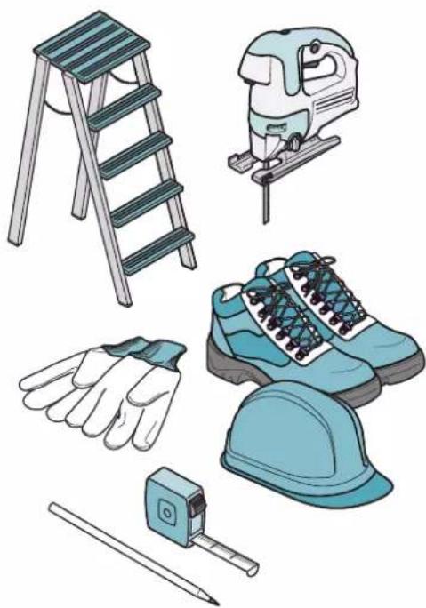
During installation, always use personal protective equipment (e.g.: Safety shoes) and adopt prudent and proper conduct.
The installation kit (screws and plugs) supplied with the hood is only to be used on masonry walls: in case of installation on walls of a different material, assess other installation options keeping in mind the type of wall surface and the weight of the hood (indicated on page 2).
Keep in mind that installations with different types of fastening systems from those supplied, or which are not compliant, can cause electrical and mechanical seal danger.
Do not install the hood outdoors and do not expose it to atmospheric elements (rain, wind, etc.).
ELECTRICAL SAFETY

The electrical system to which the hood is to be connected must be in accordance with local standards and supplied with earthed connection in compliance with safety regulations in the country of use. It must also
comply with European standards regarding radio antistatic properties.
Before installing the hood, check that the electrical mains power supply corresponds with what is reported on the identification plate located inside the hood.
The socket used to connect the installed equipment to the electrical power supply must be within reach: otherwise, install a mains switch to disconnect the hood when required.
Any changes to the electrical system must be carried out by a qualified electrician.
The maximum length of the flue fastening screws (supplied by the manufacturer) must be 13 mm. Use of non-compliant screws with these instructions can lead to danger of an electrical nature.
Do not try to solve the problem yourself in the event of equipment malfunction, but contact the Dealer or an authorised Servicing Department for repairs.

When installing the hood, disconnect the equipment by removing the plug or pining off the main switch.
FUMES DISCHARGE SAFETY

Do no connect the equipment to discharge pipes of fumes produced from combustion (for example boilers, fireplaces, etc.).
Before installing the hood, ensure that all standards in force regarding discharge of air out of the room have been complied with.
Deviation for Australia and New Zealand: Range hoods and other cooking fume extractors may adversely affect the safe operation of appliances burning gas or other fuels (including those in other rooms) due to back flow of combustion gases. These gases can potentially result in carbon monoxide poisoning.
After installation of a range hood or other cooking fume extractor, the operation of flued gas appliances should be tested by a competent person to ensure that back flow of combustion gases does not occur. (AS/NZS 60335.2.31:2013/A4:2020).
USER WARNINGS

These warnings have been drawn up for your personal safety and those of others. You are therefore kindly asked to read the net carefully in its entirety before using the planing the equipment.
The Manufacturer declines all responsibility for any damage caused directly, or indirectly, to per-
sons, things and pets as a consequence of failing to comply with the safety warnings indicated in this booklet.
It is imperative that this instructions booklet is kept together with the equipment for any future consultation.
If the equipment is sold or transferred to another person, make sure that the booklet is also supplied so that the new user can be made aware of the hood's operation and relative warnings.
After the stainless steel hood has been installed, it will need to be cleaned to remove any residues remaining from the protection adhesive as well as any grease and oil stains which, if not removed, can cause irreversible damage to the hood surface. To properly clean the unit, the manufacturer recommends using the supplied moist wipes, which are also available sold separately.
Insist on original spare parts.
INTENDED USE
The equipment is solely intended to be used to extract fumes generated from cooking food in non-professional domestic kitchens: any other use is improper. Improper use can cause damage to persons, things, pets and exempts the Manufacturer from any liability.
The equipment can be used by children over the age of 8 and by persons with reduced physical, sensory and mental abilities, or with no experience or knowledge, as long as they do so under supervision or after having received relative instructions regarding safe use of the equipment and understanding of the dangers connected to it.
Children are not to play with the equipment. Cleaning and maintenance by the user must not be carried out by children without supervision.
USE AND CLEANING WARNINGS

Before cleaning or carrying out maintenance operations, disconnect the equipment by removing the plug or switching e main switch.
Do not use the hood with wet hands or bare feet.
Always check that all electrical parts (lights, extractor fan) are off when the equipment is not being used.
The maximum overall weight of any objects placed or hung (if applicable) on the hood must not exceed 1.5 Kg.
Always supervise the cooking process during the use of deep-fryers: Overheated oil can catch fire.
Do not leave open, unattended flames under the hood.
Do not prepare food over an open flame under the hood.
Never use the hood without the metal anti-grease filters: in this case, grease and dirt will deposit in the equipment and compromise its operation.
Accessible parts of the hood can be hot when used at the same time as the cooking appliances.
Do not carry out any cleaning operations when parts of the hood are still hot.
There can be a risk of fire if cleaning is not carried out according to the instructions and products indicated in this booklet.
Disconnect the main switch when the equipment is not used for long periods of time.

If other appliances that use gas or other fuels are being used at the same time (boiler, stove, fireplaces, etc.), make sure the room where the fumes are discharged is well-ventilated, in compliance with the local regulations.
INSTALLATION
only intended for qualified personnel

Before installing the hood, carefully read the chapter "SAFETY INSTRUCTIONS AND WARNINGS".
TECHNICAL FEATURES
The technical specifications are exhibited on the labels located inside the hood.
POSITIONING
The minimum distance between the highest part of the cooking equipment and the lowest part of the hood is indicated in the installation instructions.
Generally, when the hood is placed over gas cookers, the distance must be at least 65 cm (25.6"). However, according to standard EN60335-2-31, the minimum distance between the cooker and lower part of the hood can be reduced to the quota reported in the installation instructions.
Should the instructions for the gas cooker specify a greater distance, this must be taken into consideration.
Do not install the hood outdoors and do not expose it to outdoor environment (rain, wind, etc.).
ELECTRICAL CONNECTION
(only intended for qualified personnel)

Disconnect the equipment from electrical mains power supply before carrying out any operations on the hood.
Ensure that the wires inside the hood are not disconnected or cut:
in the event of damage, contact your nearest Servicing Department.
Refer to qualified personnel for electrical connections.
Connection must be carried out in compliance with the provisions of law in force.
Before connecting the hood to the electrical mains power supply, check that:
• voltage supply corresponds with what is reported on the data plate located inside the hood;
- the electrical system is compliant and can withstand the load (see the technical specifications located inside the hood);
- the power supply plug and cable do not come into contact with temperatures exceeding 70 °C;
- the power supply system is effectively and properly connected to earth in compliance with regulations in force;
- the socket used to connect the hood is within reach.
In case of:
- devices fitted with cables without a plug: the type of plug to use is a "standardised" one. The wires must be connected as follows: yellow-green for earthing, blue for neutral and brown for the phase. The plug must be connected to an adequate safety socket.
- fixed equipment not provided with a power supply cable and plug, or any
other device that ensures disconnection from the electrical mains, with an opening gap of the contacts that enables total disconnection in overvoltage category III conditions.
Said disconnection devices must be provided in the mains power supply in compliance with installation regulations.
The yellow/green earth cable must not be cut off by the switch.
The Manufacturer declines all responsibility for failure to comply with the safety regulations.
FUMES DISCHARGE
EXTERNAL EXHAUST HOOD (SUCTION)
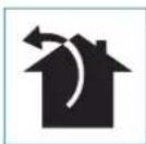
In this version the fumes and vapours are discharged outside through the exhaust pipe.
To this end, the hood outlet fitting must be connected via a pipe, to an external output.
The outlet pipe must have:
- a diameter not less than that of the hood fitting.
- a slight slope downwards (drop) in the horizontal sections to prevent condensation from flowing back into the motor.
• the minimum required number of bends. - The minimum required length to avoid vibrations and reduce the suction performance of the hood.
You are required to insulate the pipes if it passes through cold environments. In the presence of motors with 800 m3/h or higher, a check valve is present to prevent external air flowing back.
Deviation for Germany:
when the kitchen hood is used at the same time as appliances that are powered by energy other than electricity, the negative pressure in the room must not exceed 4 Pa (4 x 10⁻⁵ bar).
ASSEMBLY INSTRUCTIONS
only intended for qualified personnel

The hood can be installed in various configurations. The generic assembly steps apply to all installations; for each case, follow the specific steps provided for the required installation.
OPERATION
WHEN TO TURN ON THE HOOD?
Switch on the hood at least one minute before starting to cook to direct fumes and vapours towards the suction surface.
After cooking, leave the hood operating until complete extraction of all vapours and odours. By means of the Timer function, it is possible to set auto switch-off function which will allow the hood to turn off automatically after 15 minutes of operation.
WHICH SPEED IS TO BE SELECTED?
1st speed: maintains the circulation of clean air with low electricity consumption.
2nd speed: normal conditions of use.
3rd speed: presence of strong odours and vapours.
4th speed: rapid disposal of odours and vapours.
WHEN SHOULD THE FILTERS BE WASHED OR REPLACED?
The metal filters must be cleaned every 30 hours of operation.
For further details see the "MAINTENANCE" chap.
ELECTRONIC PUSHBUTTON PANEL
| + | + | - | # |
| Motor ON/OFFMotor OFFLong impulse: change light tone from 2700K to 5600K | ||
| + | Increase speed from 1 to 4Speed 4 is only active for a few minutes, then speed 3 activates. | The speeds are indicated by the LEDs on the keys:[IMAGE] |
| - | Reduce speed from 4 to 1 | |
| Light on/offShort impulse: turn light on and offLong impulse: adjust intensity | ||
| TIMER(red LED flashing)Auto switch-off after 15 min.The function deactivates (red LED off) if:- The TIMER key (is pressed again.- The ON/OFF key (*) is pressed. | ||

If the pushbutton panel is completely inactive, before contacting the Technical assistance service, disconnect power temporarily to the appliance (about 5"), possibly by acting on the main switch, to normal operation.
If this measure has no effect, contact the Technical assistance service.
USING THE RADIO CONTROL

WARNINGS!:
The radio control is optional.
Follow the entire procedure described below if purchased.
Place the hood away from sources of electromagnetic waves (e.g. microwave ovens), which could interfere with the radio control and with the hood electronics.
The maximum operating distance is 5 metres, that may vary according to the presence of electromagnetic interferences.
Radio control operated at 433.92MHz.
The radio control consists of two parts:
- the receiver built into the hood;
- the transmitter shown here in the figure.
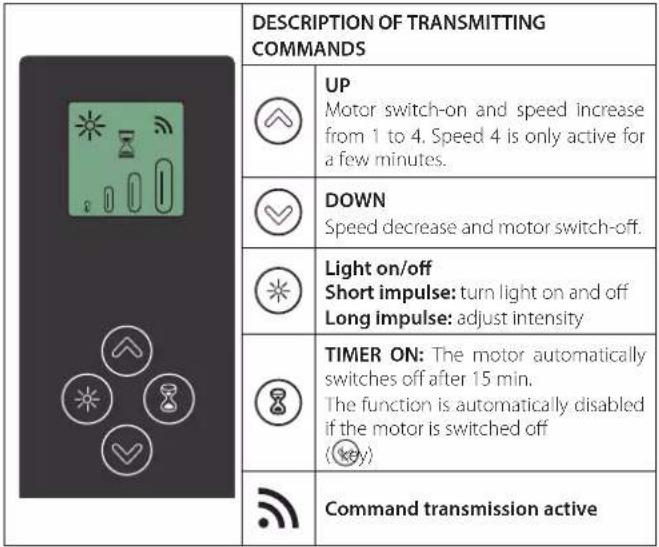 |
ACTIVATION PROCEDURE
Before using the radio control, follow the procedure below on the hood push-button panel:
- Press LIGHT and TIMER simultaneously until all LEDs start flashing.
- Release the two keys and press LIGHT 🎨 again until all LEDs are lit up.
- Release LIGHT 🔍: now the receiver is active.
This procedure is also used to deactivate the receiver.
RADIO CONTROL CODE CHANGE
With only one radio control, go directly to point 2.
With several radio controls in the same room, a new code can be created by following the procedure below.

Disconnect the power to the hood before starting the procedure.
1) - CREATE A NEW CODE
The procedure is to be carried out on the radio control.
- Press LIGHT and TIMER simultaneously until the display starts flashing.
- Press DOWN (or the radio control: saving is confirmed by three brief flash-es of the display. The new code cancels and replaces the previous default code.

Reconnect the hood to the electrical power supply, making sure that the lights and motor are off.
2) - PAIRING THE RADIO CONTROL WITH THE HOOD
USING THE ELECTRONIC PUSHBUTTON PANEL
Press TIMER 📋 on the hood pushbutton panel for 2 seconds: the red LED lights up.
press any key on the radio control within 10 seconds.
RESTORING DEFAULT CODE
The procedure is to be carried out if the hood is disposed of, sold or transferred.

Disconnect the power to the hood before starting the procedure.
- Press UP ⬆ and DOWN ⬆ simultaneously on the radio control for more than 5 seconds: reset is confirmed by three brief flashes of the display.
- Reconnect the hood to the electrical power supply.
• Proceed with associating the hood and the radio control, as described in point 2.
MAINTENANCE

Before cleaning or carrying out maintenance operations, disconnect the equipment by removing the plug or switching off the main switch.
Do not use detergents containing abrasive, acidic or corrosive substances or abrasive cloths.
Regular maintenance guarantees proper operation and performance over time. Special attention is to be paid to the metal anti-grease filters: frequent cleaning of the filters and their supports ensures that no fl ammable grease is accumulated.
CLEANING OF EXTERNAL SURFACES
You are advised to clean the external surfaces of the hood at least once every 15 days to prevent oily substances and grease from sticking to them. To clean the brushed stainless steel hood, the Manufacturer recommends using "Magic Steel" wipes.
Alternatively and for all the other types of surfaces, it can be cleaned using a damp cloth, slightly moistened with mild, liquid detergent or denatured alcohol. Finish off cleaning by rinsing well and drying with soft cloths.

Do not use too much water next to the push button control panel and lighting devices in order to prevent humidity from reaching electronic parts.
The glass panels can only be cleaned with specific, non-corrosive or non-abrasive detergents using a soft cloth.
The Manufacturer declines all responsibility for failure to comply with these instructions.
CLEANING OF INTERNAL SURFACES

Do not clean electrical parts, or parts related to the motor inside the hood, with liquids or solvents.
For the internal metal parts, see the previous paragraph.
METAL ANTI-GREASE FILTERS
It is advised to frequently wash the metal filters (at least once a month) leaving them to soak in boiling water and cleaning solution for 1 hour, taking care not to bend them.
Do not use corrosive, acid or alkaline detergents.
Rinse them well and wait for them to be completely dry before reassembling them.
They are dishwasher safe.
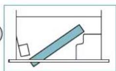
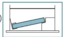
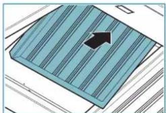
To extract and insert the metal anti-grease filters see the assembly instructions.
LIGHTING
The range hood is equipped with high efficiency, low consumption LED spotlights with extremely long duration under normal use conditions.
Should the LED spotlight need to be replaced, proceed as shown in the figure.
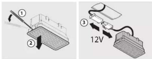
text_image
Diagram showing two electrical setups with labeled components: one with a lever and arrow, the other with a 12V power connection and cable.GREASE DRIP TRAY
It is advisable to clean the tray every 15 days.
Do not use corrosive, acid or alkaline detergents.
For more thorough cleaning, remove the oil collection tray (see figure) and wash it with hot water and washing up liquid. Rinse it well and wait for it to be completely dry before reassembling it. They are dishwasher safe.
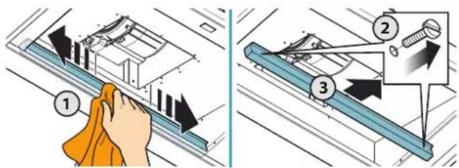
text_image
Diagram illustrating cleaning steps of a mechanical device, showing hand cleaning and three sequential steps with arrows indicating process flow.DISPOSAL AFTER END OF USEFUL LIFE

The crossed-out trash or refuse bin symbol on the appliance means that the product is WEEE, i.e. "Waste electrical and electronic equipment", accordingly it must not be disposed of with regular unsort-
ed waste (i.e. with "mixed household waste"), but it must be disposed of separately so that it can undergo specific processing for its re-use, or a specific treatment, to remove and safely dispose of any substances that may be harmful to the environment and remove the raw materials that can be recycled. Proper disposal of these products contributes to saving valuable resources and avoid potential negative effects on personal health and the environment, which may be caused by inappropriate disposal of waste.
You are kindly asked to contact your local authorities for further information regarding the designated waste collection points nearest to you. Penalties for improper disposal of such waste can be applied in compliance with national regulations.
INFORMATION ON DISPOSAL IN EUROPEAN UNION COUNTRIES
The EU WEEE Directive was implemented differently in each country, accordingly, if you wish to dispose of this appliance we suggest contacting your local authorities or dealer to find out what the correct method of disposal is.
INFORMATION ON DISPOSAL IN NON-EUROPEAN UNION COUNTRIES
The crossed-out trash or refuse bin symbol is only valid in the European Union: if you wish to dispose of this appliance in other countries, we suggest contacting your local authorities or dealer to find out what the correct method of disposal is.

WARNING!
The Manufacturer reserves the right to make changes to the equipment at any time and without prior notice. Printing, translation and reproduction, even partial, of this manual are bound by the Manufacturer's authorisation.
Technical information, graphic representations and specifications in this manual are for information purposes and cannot be divulged.
This manual is written in Italian. The Manufacturer is not responsible for any transcription or translation errors.
text_image
Weather and lighting indicator symbols including clock, plus, minus, and sun iconstext_image
Diagram showing two electrical setups with labeled components: one with a lever and arrow, the other with a 12V power connection and cable.ÖLAUFFANGWANNE
text_image
Diagram illustrating cleaning steps of a door panel, showing hand cleaning and three labeled steps with arrows.text_image
Diagram showing two electrical setups with labeled components: one with a lever and handle, the other with a 12V power connection to a device.BAC DE RÉCUPÉRATION DE L'HUILE
text_image
Diagram illustrating cleaning steps of a door panel, showing hand cleaning and three labeled steps with arrows.ÉLIMINATION EN FIN DE VIE

text_image
Diagram showing a mechanical device with labeled parts and directional arrows indicating motion or force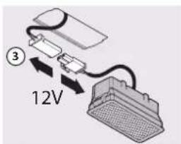
text_image
③ 12Vtext_image
Diagram illustrating cleaning steps of a washing machine, showing hand cleaning and three labeled steps with arrows.text_image
Weather and lighting indicator buttons with clock, plus, minus, and sun iconstext_image
Diagram showing two electrical setups with labeled components: one with a lever and handle, the other with a 12V power connection.text_image
Diagram illustrating cleaning steps of a washing machine, showing hand cleaning and three labeled components with arrows.text_image
Diagram showing two electrical setups with labeled components: one with a handle and arrow, the other with a 12V power outlet connected to a device.ZBIORNICZEK NA OLEJ
text_image
Diagram illustrating cleaning steps of a door panel, showing hand cleaning and three labeled steps with arrows indicating process flow.UTYLIZACJA PO ZAKOŃCZENIU OKRESU EKSPLOATACJI

VEILIGHEIDSINSTRUCTIES EN WAARSCHUWINGEN

KAP MET AFVOER NAAR BUITEN (ZUIGKAP)
text_image
Diagram showing two electrical setups with labeled components: one with a lever and handle, the other with a 12V power connection.OLIEOPVANGBAKJE
text_image
Diagram illustrating cleaning steps of a washing machine, showing hand cleaning and three labeled steps with arrows.text_image
Diagram showing two electrical setups with labeled components: one with a tool and arrow, the other with a 12V power connection and cable.CUBA DE RECOLHA DE ÓLEO
Recomenda-se de limpar a cuba cada 15 días.
text_image
Diagram illustrating cleaning steps of a washing machine, showing hand cleaning and three labeled steps with arrows.HVILKEN HASTIGHED SKAL MAN VÄLGE?
text_image
Diagram showing two electrical setups with labeled components: one with a lever and handle, the other with a 12V power supply connected to a device.BAKKE TIL OPSAMLING AF OLIE
text_image
Diagram illustrating a cleaning or repair procedure with labeled steps and directional arrows indicating process flow.BORTSKAFFELSE VED ENDT LEVETID

text_image
Diagram showing two electrical setups with labeled components: one with a lever and handle, the other with a 12V power connection via cable.OLJEUPPSAMLINGSKÄRL
text_image
Diagram illustrating cleaning steps of a washing machine, showing hand cleaning and three labeled steps with arrows.KASSERING I SLUTET AV LIVSLÄNGDEN

text_image
Diagram showing two electrical setups with labeled components: one with a handle and arrow, the other with a 12V power outlet connected to a device.ÖLJYN KERÄYSASTIA
text_image
Diagram illustrating cleaning steps of a washing machine, showing hand cleaning and three labeled steps with arrows.HÄVITTÄMINEN KÄYTÖN LOPUTTUA

10 GENERERE EN NY KODE
text_image
Diagram showing three steps of a battery or filter device with labeled components and 12V power connectionOLJEBEHOLDER
text_image
Diagram illustrating cleaning steps of a washing machine, showing hand cleaning and three labeled steps with arrows.KASSERING VED ENDT LEVETID