
BPZ12SS - Cooking accessory BLACK & DECKER - Free user manual and instructions
Find the device manual for free BPZ12SS BLACK & DECKER in PDF.

| Product Type | Pizza Oven Stand |
| Brand | Black & Decker |
| Model | BPZ12SS |
| Usage | Residential Outdoor |
| Adjustable Height | 89 cm to 115 cm |
| Load Capacity (fixed shelves) | 15.8 kg per shelf |
| Load Capacity (sliding shelf) | 4.5 kg |
| Material | Steel |
| Caster Wheels | 4 with brakes |
| Adjustable Legs | 4, by pin |
| Shelves | 3 fixed + 1 sliding |
| Included Accessories | Hex key and hex wrench, screws, washers, nuts |
| Assembly | Assembly required |
| Warranty | 2-year limited |
Frequently Asked Questions - BPZ12SS BLACK & DECKER
User questions about BPZ12SS BLACK & DECKER
0 question about this device. Answer the ones you know or ask your own.
Ask a new question about this device
Download the instructions for your Cooking accessory in PDF format for free! Find your manual BPZ12SS - BLACK & DECKER and take your electronic device back in hand. On this page are published all the documents necessary for the use of your device. BPZ12SS by BLACK & DECKER.
USER MANUAL BPZ12SS BLACK & DECKER
English (original instructions) 4
Additional Parts Referenced (Not Included)
36 Pizza oven
37 Pizza oven legs
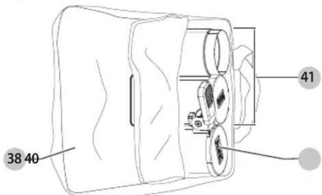
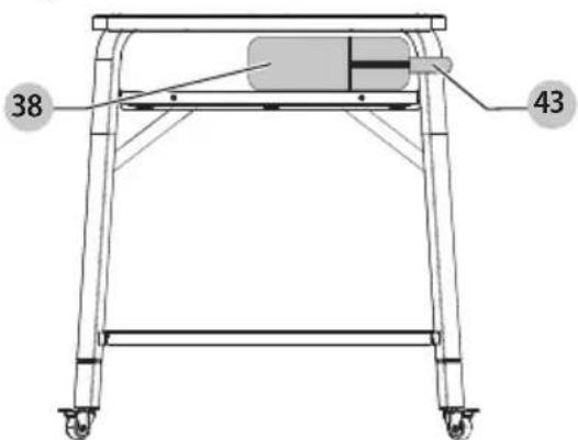
38 Oven and stand storage bag case
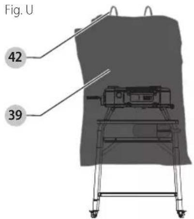
39 Oven and stand storage bag
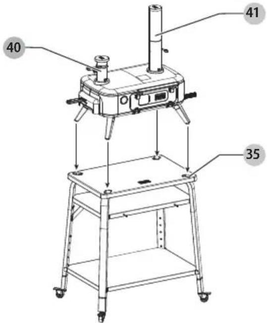
40 Pellet hopper
41 Chimney assembly
42 Bag vertical handles
43 Oven and stand storage bag case strap
44 Oven and stand storage bag horizontal straps
Composants
WARNING: Read all safety warnings and all instructions. Failure to follow the warnings and instructions may result in electric shock, fire and/or serious injury.

WARNING: To reduce the risk of injury, read the instruction manual.
Definitions: Safety Alert Symbols and Words
This instruction manual uses the following safety alert symbols and words to alert you to hazardous situations and your risk of personal injury or property damage.
DANGER: Indicates an imminently hazardous secretion which, if not avoided, will result in death or serious injury.
WARNING: Indicates a potentially hazardous situation, if not avoided, could result in death or serious injury.
CAINTION: Indicates a potentially hazardous situation, if not avoided, may result in minor or moderate injury.
(Used without word) Indicates a safety message.
NOTICE: Indicates a practice not related to personal injury which, if not avoided, may result in property damage.
Pizza Oven Stand Manual Warnings:
- To reduce the risk of injury, user must read instruction manual.
- For use on level, stable surfaces only. Use caution when rolling over uneven transitions.
• Reference pizza oven manual. - Use only with BLACK+DECKER® compatible products.
- Do not move while oven is hot.
• Metal surfaces can be hot.
• Outdoor residential use only. - Wheels should remain locked unless moving the stand.
- Do not apply unbalanced load as stand could tip over.
• Weight limit/overload: - Top, middle, and bottom shelves: 35 lbs. (15.8 kg)
- Sliding shelf: 10 lbs. (4.5 kg)
- Be cautious of sharp edges when assembling.
- Be cautious of sharp edges while moving stand.
- Do not use stand as step ladder.
- Do not modify or alter stand.
- Do not place hot items directly on shelves.
- Do not slide items across surfaces and do not scratch surfaces.
- Do not cut or scrape on any surfaces.
- Do not adjust legs while oven is on stand.
- Do not use sliding shelf to move stand.
- Ensure all fasteners are tight after assembly is complete.
- Check periodically to ensure fasteners remain tight.
Assembly
NOTE: Leave all nuts and screws loose until assembly is complete.
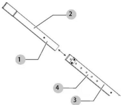
Assembling Adjustable Legs (Fig. B)
- Press the adjustable leg pin 1 on the adjustable leg inner sleeve 2 and insert the inner sleeve into the adjustable leg outer sleeve 3.
- Slide the adjustable leg inner sleeve down until the adjustable leg pin pops out of the next adjustable leg pin hole 4 and locks into place. Ensure the pin is fully engaged with the pin hole.
- Repeat for all four adjustable legs, ensuring all legs are set to the same height.
NOTE: You will have to press the adjustable leg pin each time it clicks into an adjustable leg pin hole.
Fig. B
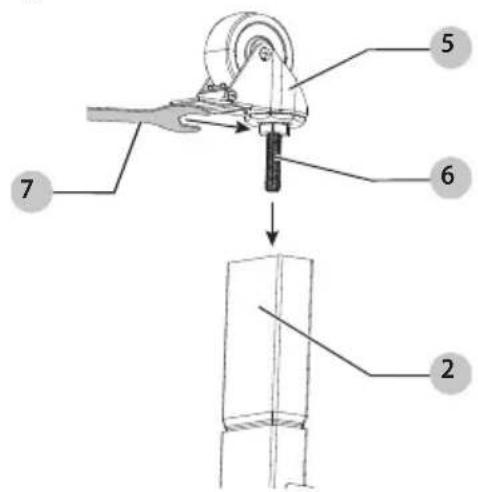
Attaching Casters (Fig. C)
- To attach a caster 5, align the caster post 6 into the hole at bottom of the adjustable leg inner sleeve 2 and use the box wrench 7 to turn clockwise until the caster is tightened as shown in Fig. C.
- Repeat for all four casters.
Fig. C
Attaching Adjustable Legs (Fig. D - F)
NOTE: Leave all nuts and screws loose until assembly is complete.
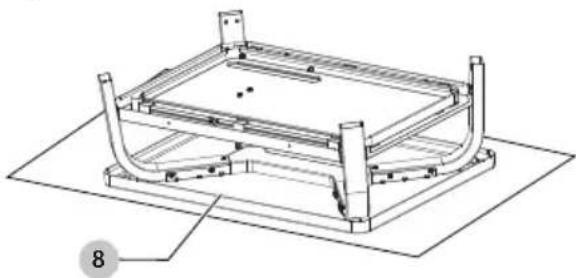
- To protect the tabletop 8 from scratches or damage while assembling, place the tabletop assembly 9 upside-down on a soft carpet, towel, or flattened box as shown in Fig. D.
- Slide the end of the adjustable leg outer sleeve 3 into the curved leg 10 as shown in Fig. E. Ensure the curved leg holes line up with the adjustable leg holes.
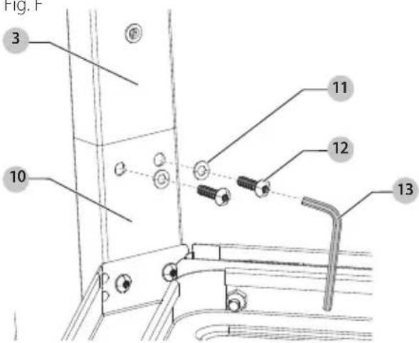
- Place the M5 washer 11 onto the M5 leg screw 12. Slide the screw through the curved leg and adjustable leg outer sleeve and tighten the screw with the hex key 13 as shown in Fig. F.
- Repeat for all four adjustable legs.
Fig. D
natural_image
Technical line drawing of a mechanical frame assembly with no visible text or symbolsFig. E
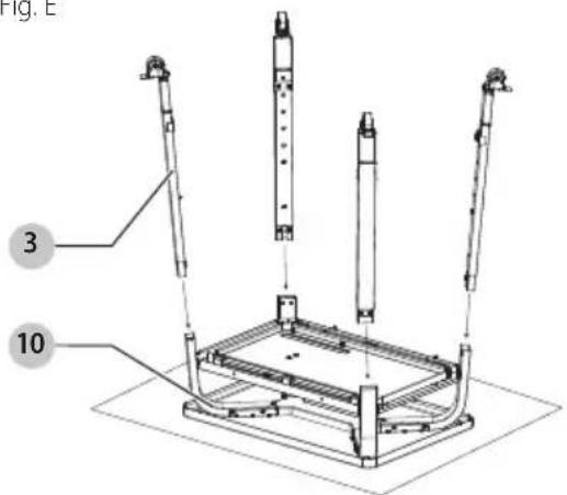
Fig. F
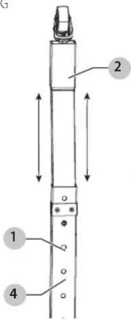
Adjusting Stand Height (Fig. G)
WARNING: Do not adjust the stand while the pizza or other objects are on it. This may result in damage or personal injury.
WARNING: Ensure all four legs are set to the same height, otherwise the stand will be unstable, resulting in damage or personal injury.
The stand can be set to different heights for custom use. The lowest height is 35" (89 cm) and the highest is 45" (115 cm). Each adjustable leg pin hole 4 is separated by 2" (5 cm) for a more customized height.
- Press the adjustable leg pin 1 fully into the adjustable leg so it is no longer engaged with the adjustable leg pin hole.
- Slide the adjustable leg inner sleeve2 up or down until the adjustable leg pin pops out of the next adjustable leg pin hole and locks into place. Ensure the pin is fully engaged with the adjustable leg outer sleeve.
- Continue until the stand is adjusted to desired height setting.
- Repeat for all four adjustable legs.
NOTE: You will have to press the adjustable leg pin each time the pin clicks into an adjustable leg pin hole.
NOTE: Do not flip stand over at this point in the assembly process. The next step requires the stand to remain upside down.
Fig. G
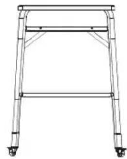
Highest setting
natural_image
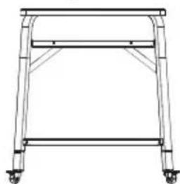
Line drawing of a four-legged table frame with wheels at both ends (no text or symbols)Lowest setting
natural_image
Line drawing of a simple metal frame structure with wheels and supports (no text or symbols)Attaching Bottom Shelf (Fig. H - J)
NOTE: Assistance may be required for this step as the bottom shelf 14 is heavy and large.
NOTE: Leave all nuts and screws loose until assembly is complete.
- Flip the bottom shelf upside down and slide it between the adjustable leg outer sleeves 3 as shown in Fig. H.
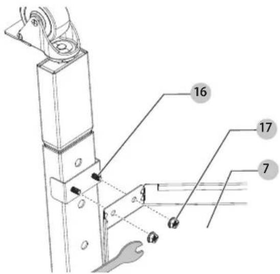
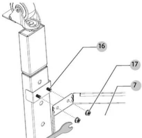
- Slide the bottom shelf holes 15 over the adjustable leg studs 16 sticking out of the adjustable legs as shown in Fig. I.
ENglIsH
- Fasten M5 serrated flange lock nuts 17 onto the adjustable leg studs with the box wrench 7 as shown in Fig. J.
- Repeat for all four corners.
Fig. H
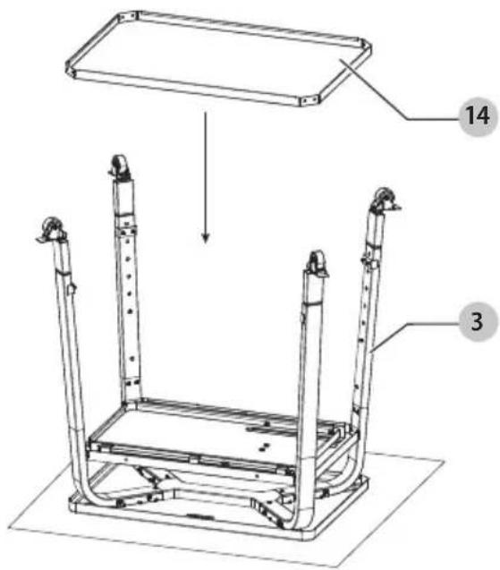
Fig.1
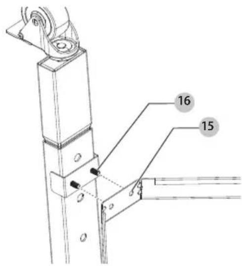
Fig. J

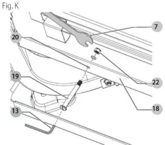
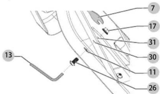
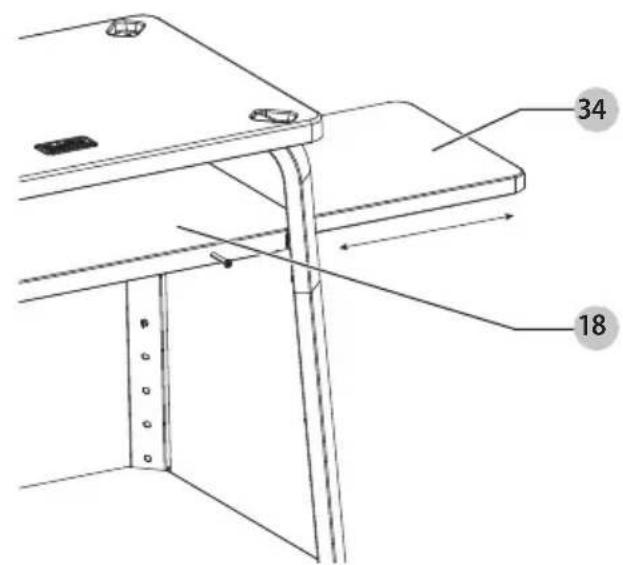
Attaching Peel Hangers (Fig. K)
Wood and metal peels can be hung off the front of the middle shelf 18.
- Slide a standoff 19 through the middle shelf standoff hole 20. NOTE: Standoff holes are on the same side of the middle shelf as the BLACK+DECKER logo 21 on the tabletop.
- Place washer 11 on threaded section of standoff and twist M5 nylon lock nut 22 clockwise onto the standoff and tighten with the box wrench 7 and hex key 13.
- Repeat for second standoff.
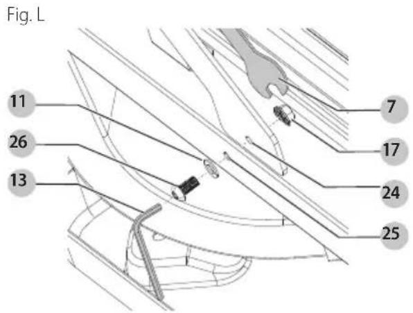
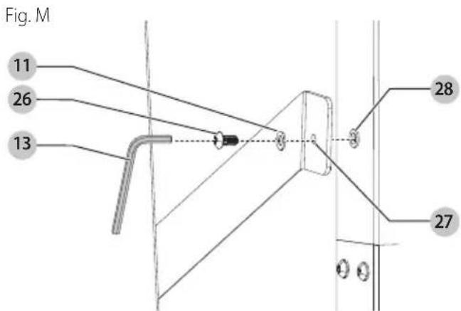
Attaching Brackets (Fig. L - 0)
NOTE: Leave all nuts and screws loose until assembly is complete.
- Align the right bracket shelf hole 24 with middle shelf right bracket hole 25. Slide the M5 washer 11 onto the M5 bracket screw 26. Slide the M5 bracket screw through both holes. Fasten the M5 serrated flange lock nut 17 onto the M5 bracket screw with hex key 13 and box wrench 7.
- Align the right bracket leg hole 27 with adjustable leg bracket hole 28. Slide the M5 washer onto the M5 bracket screw. Slide M5 bracket screw through both holes. Fasten M5 bracket screw with hex key.
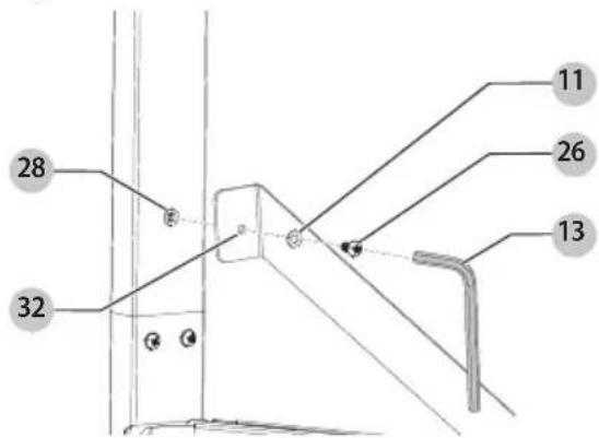
- Align the left bracket shelf hole 30 with the middle shelf left bracket hole 31. Slide the M5 washer onto the M5 bracket screw. Slide the M5 bracket screw through both holes. Fasten the M5 serrated flange lock nut onto the M5 bracket screw with the hex key and box wrench.
Fig. N
- Align the left bracket leg hole 32 with the adjustable leg bracket hole. Slide the M5 washer onto the M5 bracket screw. Slide the M5 bracket screw through both holes. Fasten the M5 bracket screw with the hex key.
Fig. O
Final Tightening
Fully tighten all nuts and screws throughout the stand to ensure stability.
Use
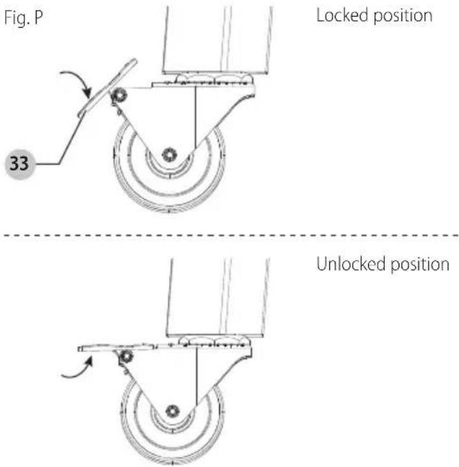
Casters (Fig. P)
• To lock the caster 5, press the end of the caster lock 33 down as shown in Fig. P.
• To unlock the caster, pull the end of the caster lock up.
Sliding Shelf (Fig. Q)
For extra shelf space, pull the sliding shelf 34 out of the side of the middle shelf 18.
Fig. Q
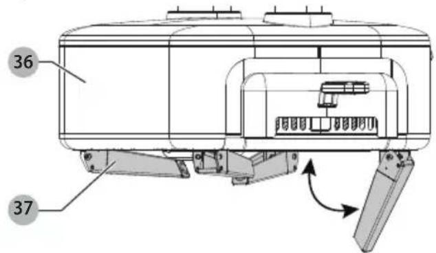
Placing Pizza Oven on Top (Pizza Oven Sold Separately) (Fig. R)
WARNING: Lock the casters before placing the pizza on the stand as it could move during placement and cause injury or misalignment.
To place the pizza oven 36 on top of the stand:
- Unfold the pizza oven legs 37 by pulling them down and away from the pizza oven.
- Place the pizza oven on top of the stand, making sure the pizza oven legs are lined up with the stand pockets 35.
Fig. R
Storage and Transportation
WARNING: Allow the oven to completely cool before and resembling and placing parts in the bag.
WARNING: Only roll casters over smooth surfaces to avoid tipping that may result in damage and personal injury.
Using The Oven and Stand Storage Bag (Sold Separately) (Fig. R - U)
- Wait for the pizza oven 36 to cool down fully. This should take roughly 60-90 minutes. Remove ashes and clean the oven as described in the pizza oven manual.
- Unzip your oven and stand storage bag case 38, then remove the oven and stand storage bag 39.
- Remove the pellet hopper 40 and chimney assembly 41 from the pizza oven (refer to Fig. S). Place the pieces in the oven and stand storage bag case.
Fig. S
- Close the oven and stand storage bag case and place the case on the middle shelf 18. Attach oven and stand storage bag case strap 43 to one of the stand legs to secure the case as shown in Fig. T.
Fig. T
- Ensure the pizza oven legs 37 are unfolded and placed in the stand pockets 35 as shown in Fig. R.
- Wrap the oven and stand storage bag over the pizza oven and stand, ensuring the bag vertical handles 42 are positioned right over the center of the oven as shown in Fig. U.
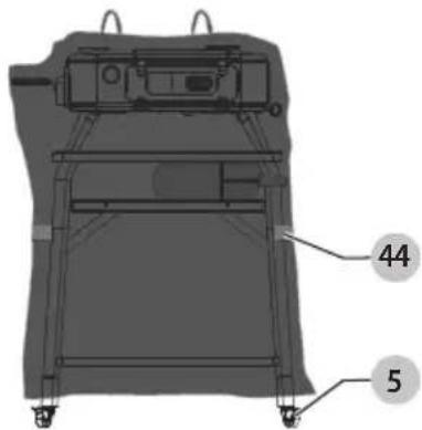
- Tighten horizontal bag straps 44 to securely hold the oven and stand storage bag around the oven and stand as shown in Fig. U.
- Unlock the casters 5 and roll the stand to its storage location.
- Lock the casters to keep the stand from rolling unintentionally when in storage.
Without the Oven and Stand Storage Bag
- Wait for the pizza oven 36 to cool down fully. This should take roughly 60-90 minutes. Remove ashes and clean the oven as described in the pizza oven manual.
- Rotate all four pizza oven legs 37 under the pizza oven as shown in Fig. R.
- Lift the oven with both hands near the center of the oven to transport. Keep the oven level with its top facing upward to make sure the pizza oven stone remains protected. Keep the oven protected from rain, sun, extreme temperatures, humidity, and other adverse weather conditions while storing.
- Once the oven has been removed, unlock casters 5 and move the stand to an environment that will protect the stand from rain, sun, extreme temperatures, humidity, and other adverse weather conditions while storing. Lock the casters to keep the stand from rolling unintentionally when in storage.
Register Online
Thank you for your purchase. Register your product now for:
- WARRANTY SERVICE: Registering your product will help you obtain more efficient warranty service in case there is a problem with your product.
- CONFIRMATION OF OWNERSHIP: In case of an insurance loss, such as fire, flood or theft, your registration of ownership will serve as your proof of purchase.
- FOR YOUR SAFETY: Registering your product will allow us to contact you in the unlikely event a safety notification is required under the Federal Consumer Safety Act.
Register online at www.blackanddecker.com/account/login.
Two-Year Limited Warranty
For warranty terms, go to
www.blackanddecker.com/warranty.
To request a written copy of the warranty terms, contact: Customer Service at Black & Decker, 701 East Joppa Road, Towson, MD 21286 or call 1-800-544-6986.
LATIN AMERICA: This warranty does not apply to products sold in Latin America. For products sold in Latin America, check country-specific warranty information contained in the packaging, call the local company or see the website for such information.
natural_image
Technical line drawing of a rectangular frame with curved supports and mounting brackets, no text or symbols presentFig. E
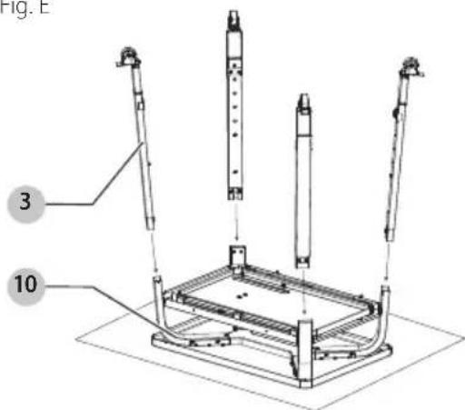
Fig. F
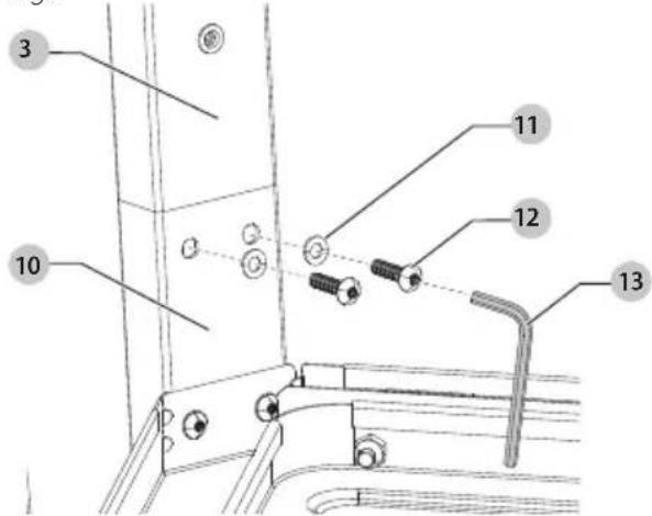
Fig.1

Fig. J
www.blackanddecker.com/warranty.
natural_image
Technical line drawing of a mechanical frame assembly with no visible text or symbolsFig. E

Fig. F
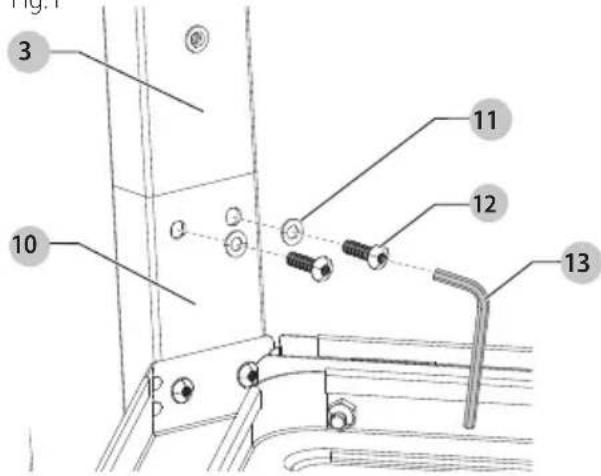
Fig.1
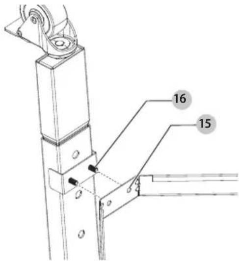
Fig. J
natural_image
Mechanical diagram showing a wheel and lever mechanism with no text or symbolswww.blackanddecker.com/account/login.
www.blackanddecker.com/warranty.