Flowclear 58677 - Pool BESTWAY - Free user manual and instructions
Find the device manual for free Flowclear 58677 BESTWAY in PDF.

| Product Type | Electrolytic Chlorinator |
| Brand | Bestway |
| Model | Flowclear 58677 |
| Maximum Chlorine Production | 6 g/h |
| Pump Flow Range | 1.25 to 11.35 m³/h |
| Recommended Salt Concentration | 3 g/L (3000 ppm) |
| Water Temperature | 10 to 36 °C |
| Ambient Temperature | 5 to 45 °C |
| Maximum Compatible Water Capacity | 26,495 L |
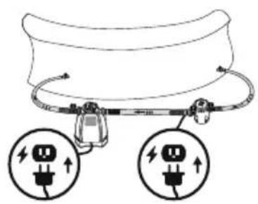
| Electrical Supply | Grounded outlet, built-in ground fault circuit breaker |
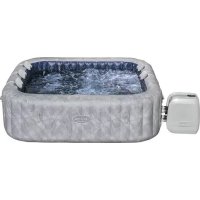
| Compatible Pool Type | Above-ground pools only |
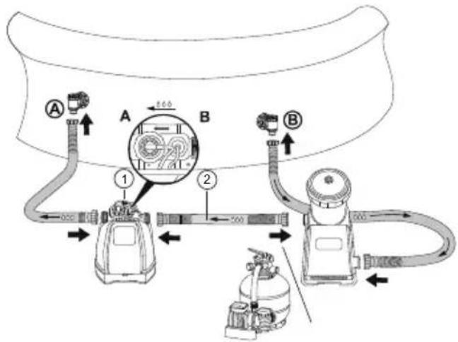
| Installation | Last position in the circulation loop (water flow direction) |
| Main Functions | Electrolytic chlorination, timer, digital display, LED indicators |
| Cell Maintenance | Monthly cleaning with water/vinegar solution (50/50) |
| Safety | Double insulation, do not use extension cord, do not bury cord |
| Spare Parts | Contact Bestway customer service (bestwaycorp.com/support) |
| Storage Conditions | Temperature between 10 °C and 38 °C, dry location |
| Warranty | Visit Bestway website |
Frequently Asked Questions - Flowclear 58677 BESTWAY
User questions about Flowclear 58677 BESTWAY
0 question about this device. Answer the ones you know or ask your own.
Ask a new question about this device
Download the instructions for your Pool in PDF format for free! Find your manual Flowclear 58677 - BESTWAY and take your electronic device back in hand. On this page are published all the documents necessary for the use of your device. Flowclear 58677 by BESTWAY.
USER MANUAL Flowclear 58677 BESTWAY
©2022 Bestway Inflatables & Material Corp.
All rights reserved/Tous droits réservés/Todos los derechos reservados/
Trademarks used in some countries under license from/
Manufactured, distributed and represented in the European Union by/
Distributed in Australia & New Zealand by Bestway Australia Pty Ltd, Unit 2/98-104 Carnarvon St Silverwater, NSW 2128, Australia
Tel: Australia: (+61) 2 9037 1388; New Zealand: 0800 142 101
Distributed in United Kingdom by Bestway Corp UK Ltd. 8 Wentworth Road, Heathfield Industrial Estate, Newton Abbot, Devon, TQ12 6TL
Exported by/Exporté par/Exportado por/Exportiert von/Esportato da
Bestway (Hong Kong) International Ltd./Bestway Enterprise Company Limited
Suite 713, 7/Floor, East Wing, Tsim Sha Tsui Centre, 66 Mody Road, Kowloon, Hong Kong
www.bestwaycorp.com

OWNER'S MANUAL
58677 Chlorinator
YouTube
Visit the Bestway YouTube channel
IMPORTANT SAFETY INSTRUCTIONS
READ AND FOLLOW ALL INSTRUCTIONS.
Carefully read, understand, and follow all information in this user manual before installing and using the Chlorinator. These warnings, instructions, and safety guidelines address some common risks, but they cannot cover all risks and dangers in all cases. Always use caution, common sense and good judgment when using the Chlorinator. Retain this information for future use. In addition, the following information can vary depending on the Chlorinator type. Keep the instruction manual in a safe place. If instructions are missing, please contact the manufacturer or search it on the website www.bestwaycorp.com.
TECHNICAL INSTRUCTIONS
IMPORTANT SAFETY INSTRUCTIONS
When installing and using this electrical equipment, basic safety precautions should always be followed, including the following:
READ AND FOLLOW ALL INSTRUCTIONS
WARNING - TO REDUCE THE RISK OF INJURY, do not permit children to use this product unless they are closely supervised at all times.
WARNING - RISK OF ELECTRIC SHOCK. Connect only to a grounding type receptacle. This product is provided with a ground-fault circuit-interrupter. If replacement of the plug is needed, use only identical replacement parts.
CAUTION - To reduce the risk of electric shock the pool must be installed no closer than 6 feet (1.8 m) from any electrical outlet. Do not place portable appliances closer than 5 feet (1.5 m) from the pool.
WARNING: This product is not intended to be bonded to the equipotential bonding grid.
DO NOT BURY CORD. Locate cord to minimize abuse from lawn mowers, hedge trimmers, and other equipment.
WARNING - To reduce the risk of electric shock, replace damaged cord immediately.
WARNING - To reduce the risk of electric shock, do not use extension cord to connect unit to electric supply; provide a properly located outlet. CAUTION - This product is for use with storable pools only. Do not use with permanently-installed pools. A storable pool is constructed so that it is capable of being readily disassembled for storage and reassembled to its original integrity. A permanently-installed pool is constructed in or on the ground or in a building such that it cannot be readily disassembled for storage.
CAUTION - For continued protection against possible electric shock this unit is to be mounted to the base in accordance with the installation instructions.
CSA ENCLOSURE 3
FOR USE WITH SWIMMING POOLS ONLY.
CAUTION: TO ENSURE CONTINUED PROTECTION AGAINST SHOCK HAZARD, USE ONLY IDENTICAL REPLACEMENT PARTS WHEN SERVICING.
WARNING: RISK OF ELECTRIC SHOCK. CONNECT ONLY TO A GROUNDING TYPE RECEPTACLE.
CAUTION: THIS PRODUCT IS FOR USE WITH STORABLE POOLS ONLY - DO NOT USE WITH PERMANENTLY-INSTALLED POOLS.
CAUTION: CONNECT ONLY TO GROUNDING TYPE RECEPTACLE PROTECTED BY A CLASS A GROUND FAULT CIRCUIT INTERRUPTER.
CAUTION: FOR CONTINUED PROTECTION AGAINST POSSIBLE ELECTRIC SHOCK THIS UNIT IS TO BE MOUNTED TO THE BASE IN ACCORDANCE WITH THE INSTALLATION INSTRUCTIONS.
WARNING - RISK OF ELECTROCUTION
1) Connect Only To Properly Grounded Outlet. Do Not Remove Ground Pin.
2) Inspect Cord Before Using – Do Not Use If Cord Is Damaged.
3) Keep Ground-Fault Circuit-Interrupter Dry And Off The Ground.
4) Do Not Touch Plug With Wet Hands.
5) Double Insulated - When Servicing Use Only Identical Replacement Parts.
6) Read Instruction Manual Before Using.
DO NOT REMOVE THIS TAG
SAVE THESE INSTRUCTIONS.
- When working with electricity, turn the electrical power off at the circuit breaker and lock breaker door. Failure to do so will result in increased risk of shock, injury and possibly death.
- DO NOT REMOVE THE GROUNDING PRONG OR MODIFY THE PLUG IN ANY WAY. DO NOT USE ADAPTOR PLUGS.
- Consult a qualified electrician for any questions related to the validity of your plugs grounding. Handle this product with care. Do not pull or carry this product by the power cord. Never pull a plug from the outlet by yanking the power cord. Keep cord free from abrasions. Sharp objects, oil, moving parts, and heat should never be exposed to this product.
- Examine equipment before use. Notify Bestway at the customer service address listed on this manual for any manufacturing defect or missing parts at the time of purchase. Verify that the equipment components represent this product model that you had intended to purchase.
- Place this product on a solid and level ground. Pay attention to position of pool and this product, so adequate ventilation, drainage, and access for cleaning is available.
- Never place this product in an area that may accumulate water, or in an area where foot traffic will flow around the pool.
• Atmospheric conditions may affect the performance and life span of this product. - Unnecessary wear and tear may occur during periods of cold, heat and exposure to sun.
- Whenever possible shelter this product from these conditions. Assembly and disassembly of this product should only be performed by adults.
SETUP
CHECK LIST
To check the parts inside the manual. Verify that the equipment components represent the model that you had intended to purchase. In case of any damaged or missing parts at the time of purchase, visit our website bestwaycorp.com/support. Drawings are for illustration purposes only. May not reflect actual product. Not to scale.
PRODUCT SPECIFICATIONS
| Maximum chlorine production per hour: | 6 g/h |
| Sand filter/Filter pump flow range: | 330-3000 gal/h |
| Salt concentration: | 3000 ppm (3 g/L) |
| Water temperature: | 10-36°C |
| Ambient temperature: | 5-45°C |
| Compatible with max water capacity: | 7000 gal (26495 L) |
RECOMMENDATIONS BEFORE INSTALLATION
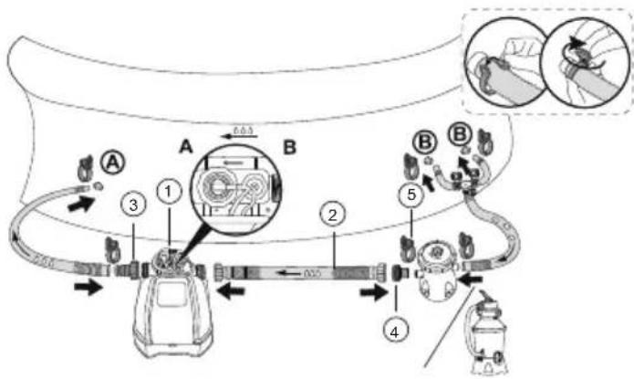
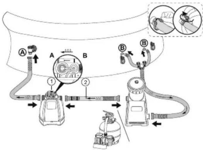
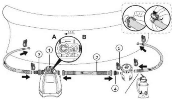
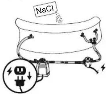
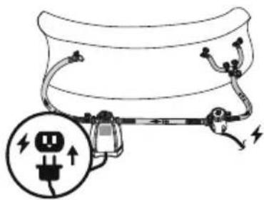
- The chlorinator must be installed at the last position of the water circulation pipe (down the direction of the water flow) as shown in "1a, 1b, 1c and 1d".
- Only use sodium chloride (NaCl) salt with a purity of at least 99.8% to fully dissolve it.
- Too low salt content will reduce the efficiency of the chlorinator and result in low chlorine production. High salt content may produce a salty taste to the pool water and it may cause corrosion to metal fixtures and fittings in the pool.
- The "Pool Salt Table" shows the correct amount of salt required. Refer to the different quantity of water. The salt in the pool will not automatically decrease.
- Only when the pool water is lost will the salt in the water decrease, and the evaporation of water will not cause the salt to decrease.
| Pool Salt Table | |||||
| Pool capacity | The amount of salt added for the first time 3.0 g/L (3000 ppm) | Display code "E1" the amount of salt that needs to be added | |||
| (gal) | (l) | (lb) | (kg) | (lb) | (kg) |
| 1000 | 3785 | 25 | 11 | 8 | 4 |
| 1500 | 5677 | 38 | 17 | 13 | 6 |
| 2000 | 7570 | 50 | 23 | 17 | 8 |
| 3000 | 11355 | 75 | 34 | 25 | 11 |
| 4000 | 15140 | 100 | 45 | 33 | 15 |
| 5000 | 18925 | 125 | 57 | 42 | 19 |
| 6000 | 22710 | 150 | 68 | 50 | 23 |
| 7000 | 26495 | 175 | 79 | 58 | 26 |
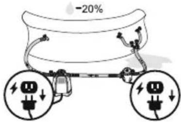
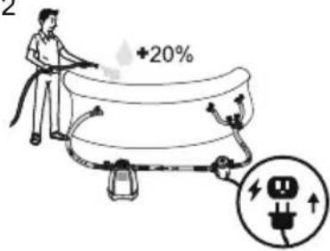
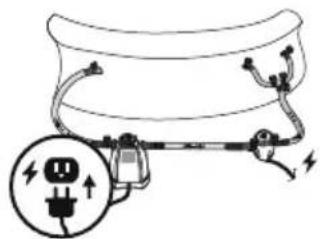
If the device shows error E2, it is necessary to reduce the salt concentration: Drain about 20% of the pool water, and then refill with clean water.
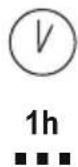
Wait 1 hour, and if the error still remains, repeat the operation until the E2 error disappears.
In case the quantity of water of your pool is not listed in the "pool salt table", follow the below formula to calculate the correct quantity of salt to add to the pool to reach the 3000 ppm of salt concentration, or in case the E1 error appears on the display.
| The amount of salt added for the first time: | The amount of salt that needs to be added if the "E1" error code displays: | ||
| (lb)Water capacity(gal)*0.025 | (kg)Water capacity(I)*0.003 | (lb)Water capacity(gal)*0.0084 | (kg)Water capacity(I)*0.001 |
USING THE CHLORINATOR
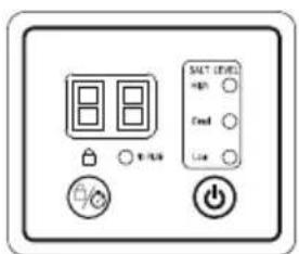
| Code number | Icon Name | Illustrate |
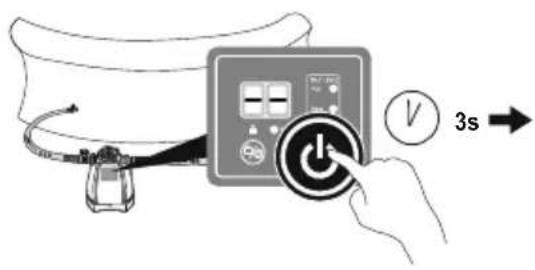
| 1 | [D808] | Power button Press and hold for 3s to turn on/off the chlorinator |
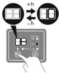
| 2 |  | Timer button Press and hold for 3s to lock/unlock, and press quickly to adjust working time |
| 3 | [S4YC] | Lock indicator When the lock indicator is unlit, the product is unlocked. If no button is pressed, the product will automatically lock after 1 minute and the Lock indicator will turn red. |
| 4 |  | Salt concentration indicator Red: The salt concentration is too high, part of the salt should be removed from the pool water. Display shows: E2; Green: The salt concentration is at the optimal level; Yellow: The salt concentration is too low and salt needs to be added to the pool water. Display shows: E1. |
| 5 |  | Water flow status indicator Shows red, no water flow or insufficient water flow |
| 6 |  | Digital Display Displays running time/remaining time/fault code Power-on state/standby mode |
Standby mode: At the end of the cycle, the display shows "00". At this time, the chlorinator will automatically enter the standby mode. The day after, approximately at the same time, it will automatically run again. If you unplug the Chlorinator, connect the plug the next day, and press the power button, the chlorinator will work according to the working hours set the previous day.
| Recommended Pool Working Time Set Table | ||||
| 1. This table shows the recommended working hours for the normal maintenance of the chlorinator connected to the pool.2. For cleaning the pool, please run it at 1.5-2 times the time shown in the table for the first use, and run it according to the normal working hours once the chlorine level is reached.3. On the first use or if the water in the pool is dirty, run the chlorinator until the level of chlorine is correct or the water is clean.Refer to the working time shown in the table below. | ||||
| Working time (hours) under different ambient temperaturesPool size | ||||
| Gallon 10 - 19°C(50 L/66°F) 20 - 28°C(68 - 82°F) 29 - 36°C(84 - 97°F) | ||||
| 1000 | 3785 | 1 | 1 | 1 |
| 2000 | 7570 | 2 | 3 | 3 |
| 3000 | 11355 | 4 | 4 | 5 |
| 4000 | 15140 | 5 | 6 | 7 |
| 5000 | 18925 | 6 | 7 | 8 |
| 6000 | 22710 | 7 | 8 | 9 |
| 7000 | 26495 | 8 | 9 | 10 |
It is recommended to cover the surface of the pool during the operation of the product to help increase the level of chlorine in the pool.
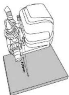
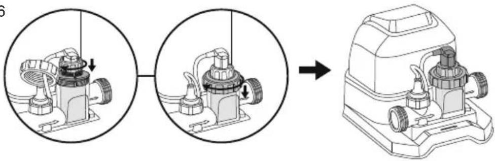
ATTACHING A BASE TO THE CHLORINATOR
Follow the below instructions. There must be two holes with a diameter of 8 mm and a spacing of 165 mm on the base. The product can be fixed on a cement base or a wooden platform. The total weight of the base should not be less than 18 kg to protect the chlorinator from accidentally falling over.
natural_image
Technical line drawing of a sewing machine with base plate and measurement scale (no text or symbols)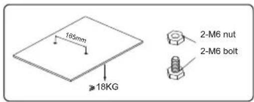
MAINTENANCE
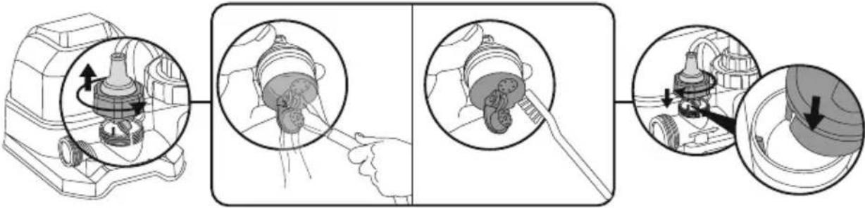
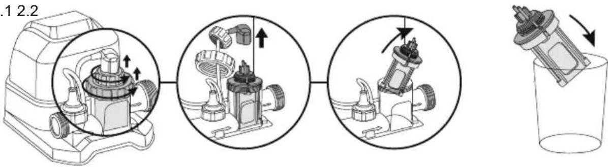
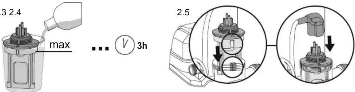
ELECTROLYTIC CELL
To clean the electrolytic cell, follow the instruction in the section [icon], Drawings are for illustration purposes only. May not reflect actual product. Not to scale. In order to maintain the best results, we recommend opening and checking the electrodes every month. However, if the water quality of the swimming pool is hard water (high content of calcium and magnesium ions), the electrodes may need to be cleaned manually on a regular basis. To clean the electrolytic cell, it is suggested to use a solution of 50% water/ 50% vinegar, or check with your pool dealer the suitable chemical product. Be sure to avoid chemical product that can damage the Titanium plate.
WATER CHEMICAL BALANCE
| Minimum | Best Value | Maximum | |
| Available chlorine | 0 | 0.5 - 3.0 ppm | 3.0 ppm |
| Combined chlorine | 0 | 0 | 0.2 ppm |
| pH value | 7.2 | 7.4 - 7.6 | 7.8 |
| Total alkalinity | 40 ppm | 80 - 100 ppm | 120 ppm |
| The hardness of calcium | 50 ppm | 100- 250 ppm | 350 ppm |
| Stabilizer (cyanuric acid) | 10 ppm | 20 - 40 ppm | 50 ppm |
- If the concentration of chlorine exceeds the recommended level, it can be dangerous to use the pool. Test the chemical balance before using the pool. If using the test strip, check the expiration date, as the test result may be inaccurate if passed the expiration date.
BESTWAY® TEST STRIPS (INCLUDED IN THE PRODUCT)
The test strips can test the concentration of "free chlorine", "PH" and "total alkalinity" in the water at the same time. It is recommended to check the level of the chemical in the water every day and before use.
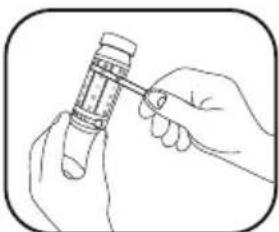
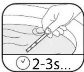
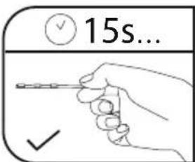
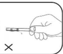
- Immerse a whole strip of test paper in water and take it out immediately.
- Keep the test paper level and wait for 15 seconds. Do not shake off excess water.
- Please compare the "free chlorine", "PH" and "total alkalinity" grades of the test paper with the color plate attached to the bottle.
STORAGE
- Remove all accessories; be sure to clean and dry all before the storage. If all the parts are not completely dry, mold may result. We strongly recommend to disassemble the Chlorinator when the environment temperature is below 10^ / 50^ .
- Store the Chlorinator in a dry place with a moderate temperature between 10^ / 50^ and 38^ / 100^ .
WARRANTY TERMS
For information concerning warranty terms, visit our website at: www.bestwaycorp.com.
TROUBLESHOOTING
| Problems | Probable Causes Solutions | |
| Insufficient chlorine concentration | The running time of the product is not long enough.The salt concentration is not enough (less than 2000 ppm).The electrolyzer is blocked or left with dirt.Increase in swimmers.Strong exposure to the sun leads to the emission of chlorine. | Please increase the running time of the product every day. For details, please refer to "Operation Instructions".Adjust the salt concentration by referring to the "Pool Salt Table".If necessary, please disassemble the electrolytic cell for inspection and cleaning. Please refer to "Maintenance".Please increase the running time of the product every day. When the pool is not in use or the product is running, please cover the pool cover.Please increase the running time of the product every day. During the running of the product, you can cover the surface of the pool and wait 2 days before using the test paper to test. |
| Flocculent precipitation in water | There is too much calcium in the pool water. | Empty about 20%-25% of the pool water volume, then add clean water to reduce the hardness. If necessary, please disassemble the electrolytic cell for inspection and cleaning. |
| LED indicator has no display code | Not plugged in.The GFCI plug is not set.The LED indicator fails. | Plug in the power plug.Press the reset button again.Please contact Bestway Customer Service Center for replacement. |
ERROR CODES
| Problems Probable | Causes Solutions | |
| Display code "E0" | No water flow. | Make sure the filter is connected to the chlorinator and is running. See "Installation Instructions" |
| The water flow is less than 280 gal/h (1050 L/h), the circulation system is blocked. | If there is a water stop valve, make sure that the water stop valve is open. Ensure that the filter element and the electrolytic cell are clean and free of dirt or impurities. Exhaust the air from the entire circulation system. Please refer to the filter manual. | |
| The direction of the inlet and outlet is reversed. | Check the direction of the water inlet and outlet. If necessary, readjust the water pipe. See "Installation Instructions". | |
| Dirt in the water flow sensor. | Make sure the water flow sensor is clean (especially the rotor). Please refer to "Maintenance". | |
| The power cord of the water flow sensor is loose. | Reconnect the water flow sensor firmly. | |
| Water flow sensor failure. Please contact Bestway Customer Service Center for replacement. | ||
| Display code "E1" | Dirt remains in the electrolyzer. | If necessary, remove the electrode to check and clean it. Please refer to "Maintenance". |
| Low salt concentration or no salt. | Add salt. Please refer to "Pool Salt Table". | |
| The electrolysis power cord is loose. | Make sure that the electrolytic cell line is firmly connected to the plug of the electrolytic cell. | |
| The electrolyzer may fail. | Please contact Bestway Customer Service Center for replacement. | |
| Display code "E2" | Salt concentration is too high. | Drain part of the pool water and add some clean water. Refer to "Salt and Pool Water Consumption" |
| Display code "E3" | Electrolyzer short circuit. | If necessary, remove the electrode to check and clean it. Please refer to "Maintenance" |

SPÉCIFICATIONS DU PRODUIT
natural_image
Technical line drawing of a mechanical device with a 165mm scale indicator (no text or symbols present)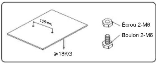
ENTRETIEN
BANDELETTES DE TEST BESTWAY® (INCLUDES DANS LE PRODUIT)
CONDITIONS DE GARANTIE
natural_image
Technical line drawing of a sewing machine with base plate and measurement scale (no text or symbols)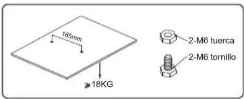
MANTENIMIENTO
CÉLULA ELECTROLÍTICA
natural_image
Technical line drawing of a sewing machine with base plate and measurement scale (no text or symbols)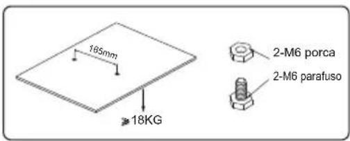
MANUTENÇÃO
CÉLULA ELETROLÍTICA
natural_image
Line drawing of a portable device with a coiled cable on top (no text or symbols)①

②

1a
1b
1c
1d
2
3
1
2

3
natural_image
Diagram of a cable or electrical plug with a fuse and plug socket, showing electrical connections without any text or symbols.
1
2
3
4
natural_image
Diagram of a cable or electrical plug with a fuse and socket, no text or symbols present
1.21.1 1.3
2.1 2.2
2.3 2.4
2.6
natural_image
Diagram showing a mechanical assembly process: before and after assembly, with no visible text or symbols.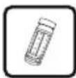
natural_image
Hand holding a pen, no text or symbols visible