AX 1360P - Measuring equipment METRIX - Free user manual and instructions
Find the device manual for free AX 1360P METRIX in PDF.

| Product type | Multichannel programmable DC power supply |
| Brand | Metrix (Chauvin Arnoux) |
| Model | AX 1360P |
| Dimensions (W x D x H) | 250 x 310 x 150 mm |
| Weight | 7.5 kg |
| Mains power supply | 220 V ±10%, 50/60 Hz, 500 VA max |
| Number of output channels | 3 (CH1, CH2, CH3) |
| CH1/CH2 output voltage (independent) | 0 ~ 30 V |
| CH1/CH2 output current (independent) | 0 ~ 3 A |
| CH1/CH2 output voltage (series) | 0 ~ 60 V |
| CH1/CH2 output current (series) | 0 ~ 3 A |
| CH1/CH2 output voltage (parallel) | 0 ~ 30 V |
| CH1/CH2 output current (parallel) | 0 ~ 6 A |
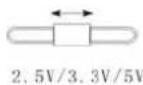
| CH3 output voltage | 2.5 V / 3.3 V / 5 V (selectable) |
| CH3 output current | 3 A max |
| Display | 3-digit LED voltmeter, 3-digit LED ammeter |
| Voltage/current resolution | 100 mV / 10 mA |
| Accuracy (voltage and current) | ±(0.5% reading + 2 digits) |
| Residual ripple (voltage) | ≤ 1 mVrms |
| Residual ripple (current) | ≤ 3 mArms |
| Protections | Overvoltage, overcurrent, overload, excessive temperature, short circuit, reverse polarity |
| Remote control interface | USB (slave port) |
| Operating modes | Independent, series tracking, parallel tracking |
| Configuration memory | 4 slots (save/recall) |
| Operating temperature range | 0 °C to 40 °C |
| Operating relative humidity | ≤ 80 % |
| Cleaning | Damp cloth and mild soap |
| Warranty | 1 year |
| Included accessories | Manual, mains cable, USB cable, LV/LW drivers |
Frequently Asked Questions - AX 1360P METRIX
User questions about AX 1360P METRIX
0 question about this device. Answer the ones you know or ask your own.
Ask a new question about this device
Download the instructions for your Measuring equipment in PDF format for free! Find your manual AX 1360P - METRIX and take your electronic device back in hand. On this page are published all the documents necessary for the use of your device. AX 1360P by METRIX.
USER MANUAL AX 1360P METRIX
text_image
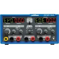
meleix® AX 1360-P Circuit board 201 Power Supply CH2 CH1 20.0 20.0 V 0.10 0.10 A VOLTAGE Power Current Power Voltage Ground Ground Ground Ground Ground Ground Ground Ground Ground Ground Ground Ground Ground Ground Ground Ground Ground Ground Ground Ground Ground Ground Ground Ground Ground Ground Ground Ground Ground Ground Ground Ground Ground Ground Ground Ground Ground Ground Ground Ground Ground Ground Ground Ground Ground Ground Ground Ground Ground Ground GND SA GND BND BND BND BND BND BND BND BND BND BND BND BND BND BND BND BND BND BND BND BND BND BND BND BND BND BND BND BND BND BND BND BND BND BND BND BND BND BND BND BND BND BND BND BND BND BND BND BND BND BNDmetrix
Multi-channel Programmable DC Power Supply
User's Manual....28
FR - Sommaire
natural_image
Technical line drawing of a mechanical component with a screwdriver inserted into a housing and a separate housing with a cylindrical shaft (no text or symbols)natural_image
Diagram showing a 3D mechanical component with an arrow indicating transformation or assembly (no text or symbols present)Type de fusible 220 V / 230 V : T3,15 A / 250 V, 5 x 20 mm
Tension constante Courant constant
(master & slave)
VOLTAGE

(Fine control)

General Instructions Chapter I
Introduction 29
Precautions....29
Safety measures....29
Operation environment 30
Guarantee 30
Maintenance, repairs, metrological checks 30
Cleaning......
Fuse replacement 31
Description of the instrument Chapter II
Introduction 32
Main Features 33
Front panel overview 34
Display
Control panel 35
Terminals
Rear panel overview 37
CC / CV characteristics .... 37
Setup Chapter III
Power up 38
Load cable connection 38
Output ON/OFF 39
Beep ON/OFF 39
Front panel lock 39
Operation
Chapter IV
-
CH1/CH2 independent mode 40
-
CH3 independent mode.... 41
-
CH1/CH2 tracking serial mode 42
3.1 Tracking serial without common terminal 42
3.2 Tracking serial with common terminal 42
- CH1/CH2 tracking parallel mode 45
Save / RECALL
Chapter V
Save setup 46
Recall setup 46
Remote control
Chapter VI
Remote control setup 47
Command Syntax......47
Error messages 48
Command list 48
Command details 49
Contents for command HELP 51
Technical Specifications
Chapter VII
52
Mechanical Specifications, Supply
Chapter VIII
53
General Instructions
| Introduction | You have just purchased an AX 1360P Multi-channel Programmable DC Power Supply and we appreciate your confidence. |
| Precautions | To obtain the best service:- read this notice carefully,- respect the safety instructions.Failure to respect the warnings and/or usage instructions may damage the device and/or installations and may be dangerous for the user. |
| Safety measures | Before plugging into local AC mains, check and make sure that the output voltage is compatible to the load. (It is suggested to disconnect a load before plugging into local AC mains).The max. output voltage of the instrument may be over 60VDC and current 6A → avoid touch the metal contact part of the output terminals.Do not use the instrument in a dusty place or a highly humid place as such will cause instrument reliability degradation and instrument failures.Install the instrument in a place where the ambient temperature is in range of -10~70°C. Note that the instrument operation may become unstable if it is operated in an ambient temperature exceeding the range of 0~40°C.Do not obstruct the ventilation holes.Only use with safety leads, diameter of which is appropriated to output current. |
| Power supply | AC Input voltage: 220 V ± 10 %, 50/60Hz, 500 VA max.Connect the protective grounding conductor of the AC power cord to an earth ground to avoid electrical shock. |
| Symbols on the instrument | Warning: potential hazard, refer to the user's manual.Selective waste sorting for recycling electric and electronic waste.In compliance with the WEEE 2002/96/EC directive:the device should not be considered as household waste.Earth terminalFuseUSB hostEuropean conformity |
| Fuse | Fuse type: 220V/230V: T3.15 A / 250 V, 5 x 20 mmMake sure the correct type of fuse is installed before power up.Replace the AC fuse with the same type and rating as the original fuse.Disconnect the power cord before fuse replacement.Make sure the cause of fuse blowout is fixed before fuse replacement. |
General Instructions (contd.)
Operation Environment
- Location: Indoor, no direct sunlight, dust free, almost non-conductive pollution (note below)
• Relative Humidity: < 80% - Altitude: < 2000m
• Temperature: 0 to 40°C
(Pollution Degree) IEC 61010-1: specifies the pollution degrees and their requirements as follows. The instrument falls under degree 2.
Pollution refers to “addition of foreign matter, solid, liquid, or gaseous (ionized gases), that may produce a reduction of dielectric strength or surface resistivity”.
Pollution degree 2: Normally only non-conductive pollution occurs. Occasionally, however, a temporary conductivity caused by condensation must be expected.
Definition of measurement categories
Overvoltage category II is for equipment intended to be supplied from the building wiring. It applies both to plug-connected equipment and to permanently connected equipment.
Overvoltage category III is for equipment intended to form part of a building wiring installation. Such equipment includes socket outlets, fuse panels, and some mains installation control equipment.
Overvoltage category IV is for equipment installed at or near the origin of the electrical supply to a building, between the building entrance and the main distribution board. Such equipment may include electricity tariff meters and primary overcurrent protection devices.
Guarantee
This equipment is guaranteed for all manufacturing and parts defects in compliance with the general terms and conditions which are available on request
During the 1 year guarantee period, the instrument may only be repaired by the manufacturer who reserves the right to make the decision to either repair or replace all or part of the appliance. In the event of a return of the equipment to the manufacturer the shipping charge from the customer to the manufacturer is at the customer's expense.
The guarantee does not apply in the following conditions:
- inappropriate use of the equipment or use with incompatible equipment
• one or more changes made to the equipment without prior explicit - authorisation from the manufacturer's technical department
- an intervention is made on the instrument by a person not approved by the manufacturer
- the adapting to a specific application that is not part of the definition of the instrument or in the operating guide
- damage caused by a mechanical shock, by dropping the instrument or by flooding.
General Instructions (contd.)
Maintenance, repairs, metrological checks
The device includes no parts that can be replaced by the operator. All operations must be carried out by competent approved personnel.
For checks and calibrations, contact one of our accredited metrology laboratories (information and contact details available on request), at our Chauvin Arnoux subsidiary or the branch in your country.
Cleaning
No interventions are authorised inside the instrument.
- Turn the instrument off (remove the power supply cable).
- Clean using a damp cloth and soap.
- Never use abrasive products or solvents.
- Dry quickly using a dry cloth or an air blower at max. 80°C.
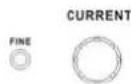
Fuse replacement
Steps
- Take off the power cord and remove the fuse socket using a minus driver.
natural_image
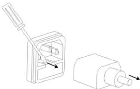
Technical line drawing of a mechanical component with a lever and pin, showing a disassembly or assembly (no text or symbols present)- Replace the fuse in the holder.
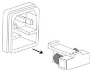
natural_image
Diagram showing a device interior with a rectangular housing and a separate 3D component, no text or symbols present.Type of fuse
220 V / 230 V : T3.15 A / 250 V, 5 x 20 mm
Description of the instrument
Introduction
Regulated programmable DC power supply is light weight, adjustable, multifunctional work stations. It has three independent outputs: two with adjustable voltage level and one with fixed level selectable from 2.5V, 3.3V and 5V. The power supply can be used for logic circuits where various output voltage or current are needed, and for tracking mode definition systems where positive and negative voltages with good accuracy are required.
Independent /Tracking Series /Tracking Parallel
The output modes of the power supply - independent, tracking series, and tracking parallel - can be selected by pressing the TRACKING key on the front panel. In the independent mode, the output voltage and current of each channel are controlled separately. The isolation degree, from output terminal to chassis or from output terminal to output terminal, is 300V. In the tracking modes, both the CH1 and CH2 outputs are automatically connected in series or parallel; no need to connect output leads. In the series mode, the output voltage is doubled; in the parallel mode, the output current is doubled.
Constant Voltage/Constant Current
Except for CH3, each output channel is completely transistorized and well-regulated, and works in constant voltage (CV) or constant current (CC) mode. Even at the maximum output current, a fully rated, continuously adjustable output voltage is provided. For a big load, the power supply can be used as a CV source; while for a small load, a CC source. When in the CV mode (independent or tracking mode), output current (overload or short circuit) can be controlled via the front panel. When in the CC mode (independent mode only), the maximum (ceiling) output voltage can be controlled via the front panel. The power supply will automatically cross over from CV to CC operation when the output current reaches the target value. The power supply will automatically cross over from CC to CV when the output voltage reaches the target value. For more details about CV/CC mode operation, see page 41.
Automatic Tracking Mode
The front panel display (CH1, CH2) shows the output voltage or current. When operating in the tracking mode, the power supply will automatically connect to the auto-tracking mode.
Description of the instrument (contd.)
Main Features
| Model Output Voltmeter Ammeter USB Interface | |||
| AX 1360P | 0 ~ 30 V x 20 ~ 3 A x 2Fixed2.5 V / 3.3 V / 5 V3 A | 3 digits LED 3 digits LED | √ |
| Performance | Low ripple & noise, intelligent cooling fanCompact design, light weight | ||
| Operation | Constant voltage/constant current operationTracking serial/tracking parallel operationOutput ON/OFF controlPanel lock function4 programming presets for voltage and current save/recallCoarse and fine control for voltage and currentSoftware calibration (only for 3300U series)Beeper outputVoltage and current limit preset | ||
| Protection | Over voltage, over current, over load, over temperature protectionsReverse polarity protection | ||
| Interface | USB interface for remote PC controlLV / LW drivers available on our website | ||
Description of the instrument (contd.)
Front panel
Overview
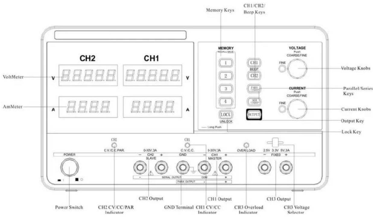
text_image
CH1/CH2/ Beep Keys Memory Keys VOLTAGE Push COARSE/FINE FINE Voltage Knobs VoltMeter V CH2 CH1 V PARA UNDERP SNE UNDERP OUTPUT CURRENT Push COARSE/FINE FINE Parallel/Series Keys Current Knobs Output Key AmMeter A A A LONG Push CH2 C.V/C.C.PAR. 0-30V 3A CH1 C.V.C.C. C.V.C.C. 0-30V 3A OVER LOAD 2.5V 3.3V 5V.3A POWER CH2 SLAVE GND CH1 MASTER FIREO + SERIAL OUTPUT COM + PARRA OUTPUT + CH2 Output CH1 Output CH3 Overload Indicator CH2 Output CH2 CV/CC/PAR Indicator GND Terminal CH1 CV/CC Indicator CH3 Overload Indicator CH3 Voltage SelectorDisplay
Voltmeter Displays CH1 or CH2 output voltage
V
(3 digits)
Ammeter Display CH1 or CH2 output current
A
(3 digits)
Description of the instrument (contd.)
| Control Panel | ||
| Memory keys |  | 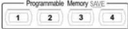 Saves or recalls panel settings. Max. 4 sets for programming preset. Refer to p. 46 for details. Saves or recalls panel settings. Max. 4 sets for programming preset. Refer to p. 46 for details. |
| CH1/CH2 beep keys |  |  Selects the output channel for level adjustment.Refer to p. 39 for level setting detailsPressing and holding CH2 key enables beep sound. Selects the output channel for level adjustment.Refer to p. 39 for level setting detailsPressing and holding CH2 key enables beep sound. |
| Parallel/Serial keys | [OOA2] | Activates Tracking Parallel operation or Tracking Serial operation. Refer to p. 35 for details. |
| Lock key |  | Locks or unlocks the front panel settings.Refer to p. 11 for details. |
| Output key |  | Turns the output on or off. |
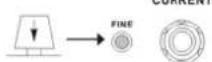
| Voltage knobs | [VOLTAGE][HKX4] | Adjusts the output voltage level for CH1 or CH2. Pressing the knob switches for coarse and fine level setting. When in fine adjustment, the FINE indicator lights on. |
| Current knobs | [H6Y2] | CURRENTAdjusts the output current level for CH1 or CH2. Pressing the knob switches coarse and fine level setting. When in fine adjustment, the FINE indicator lights on. |
Description of the instrument (contd.)
| Terminals | ||
| Power switch |  | Turns on or off the main power. Refer to page 38 for power up sequence. |
| GND terminal |  | Accepts a grounding wire. |
| CH1 output | 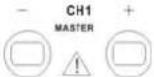 | Outputs CH1 voltage and current. |
| CH1 CV/CC indicator | [KWCT] | Indicates CH1 constant voltage or constant current operation mode. |
| CH2 output | 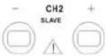 | Outputs CH2 voltage and current. |
| CH2 CV/CC/PAR indicator | [CCCW] | Indicates CH2 constant voltage, constant current or tracking parallel operation mode. |
| CH3 output | 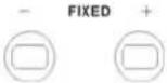 | Outputs CH3 voltage and current. |
| CH3 overload indicator | [AZW7] | Indicates when CH3 output current is overloaded. |
| CH3 voltage selector |  | Selects CH3 output voltage from 2.5 V, 3.3 V, 5 V. |
| FINE indicator | [ZZTS] | Indicates when there is fine adjustment operation for voltage or current. |
Description of the instrument (contd.)
Rear Panel Overview
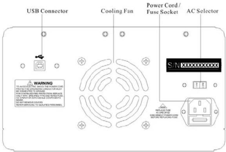
text_image
USB Connector Cooling Fan Power Cord/ Fuse Socket AC Selector WARNING TO AVOID ELECTRIC SHOCK THE POWER COLD PROTECT THE GRANDING CONDUCTOR MUST BE CONNECTED TO GROUND FOR CONTINUED FIRE PROTECTION REPLACE ONLY WITH SPECIFIED TYPE AND RATED FUSE, NO SPRING OR SERVICIABLE COMPONENTS INDEE DO NOT REMOVE COVERS REFER SERVIONS TO QUALIFIED PERSONNEL S/N xxxxxxxxxxxx REPLACE FUSE AS SPECIFIED DISCONNECT POWER COLD BEFORE REPLACING FUSEUSB connector
Accepts a USB slave connector for command-based remote control via PC.
Power cord/fuse socket

The power cord socket accepts the AC mains. The fuse holder contains the AC main fuse.
CV / CC
Characteristics
Background
The instrument automatically switches between constant voltage mode (CV) and constant current mode (CC), according to load condition.
CV mode
When the current level is smaller than the output setting, the instrument operates in Constant Voltage mode. The indicator on the front panel turns green (C.V.) The Voltage level is kept at the setting and the Current level fluctuates according to the load condition until it reaches the output current setting.
CC mode
When the current level reaches the output setting, the instrument starts operating in Constant Current mode. The indicator on the front panel turns red (C.C.) The Current level is kept at the setting but the Voltage level becomes lower than the setting, in order to suppress the output power level from overload. When the current level becomes lower than the setting, the instrument goes back to the Constant Voltage mode.
Diagram
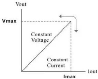
text_image
Vout Vmax Constant Voltage Constant Current Imax Imax IoutSetup
This chapter describes how to properly power up the power supply before operation.
Power Up
Connect AC power cord
Connect the AC power cord to the rear panel socket.

Power on
Press the power switch to turn on the power. The display shows the initialization screen with the model name, followed by the last recalled settings.

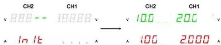
text_image
CH2 CH1 CH2 CH1 v 888-- 18888 v v 10.0 20.0 v A In Itb ... A 100 2.000 APower off
Press the power switch again to turn off the power.

Load Cable Connection
Banana plug
Insert the ∅ 4 mm safety banana plug GND

Wire type
When using load cables other than the attached, make sure they have enough current capacity for minimizing cable loss and load line impedance. Voltage drop across a wire should not excess 0.5 V. The following list is the wire current rating at 450 A/c.
Wire size (AWG) Max. current (A)
| 20 2.5 |
| 18 4 |
| 16 6 |
| 14 10 |
| 12 16 |
Setup (contd.)
| Output ON / OFF | |
| Panel operation | Pressing the Output key turns on all CH 1/2/3 outputs.The key LED also turns on. Pressing the Output key again turns off the output and the key LED. |
| Automatic output off | Any of the following actions during output on automatically turns it off.They might involve sudden change in the output level.Change the operation mode between independent / tracking series / tracking parallelRecalling other setups from the memoryStoring the setup into the memory |
| Beep ON / OFF | |
| Panel operation | By default, the beeper sound is enabled. To turn off the beep, press the beep key for 2 seconds.A beep sound comes out and the beeper setting will be turned off. To enable the beeper, press the beep key again for 2 seconds. |
| List of beeper | The following operations go with a beep sound when the beeper setting is on.Power onINDEP – SER – PAR mode switchingSetup save/recallVoltage/current knob, fine/coarse knobOutput on/offPanel lock/unlockCH1/CH2 output level knobVoltage/current level reaching minimum and maximum (zero) level |
| Front Panel Lock | |
| Panel Operation | Press the LOCK key to lock the front panel key operation.The key LED turns on. To unlock, press the LOCK key for 2 seconds.The key LED also turns off.The OUTPUT key is not affected by the lock operation. |
Operation
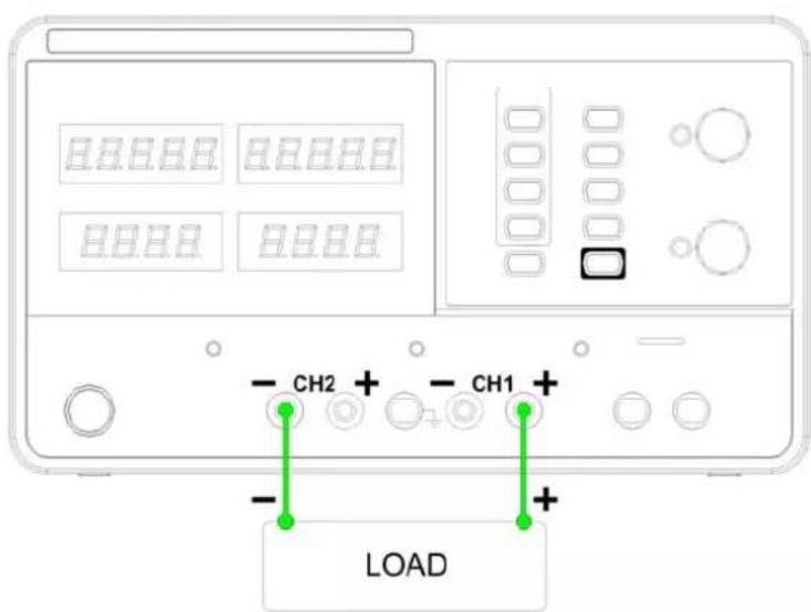
1. CH1/CH2 Independent Mode
Background / Connection CH1 and CH2 outputs work independent of each other and are separately controlled.
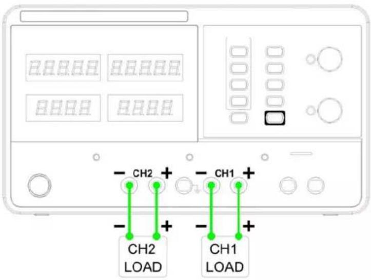
text_image
CH2 CH1 CH2 LOAD CH1 LOADOutput rating 0 \~ 30 V / 0 \~ 3 A for each channel
Panel operation
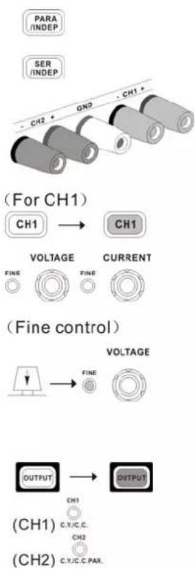
flowchart
graph TD
    A["PARA /INDEP"] --> B["For CH1"]
    C["SER /INDEP"] --> B
    B --> D["CH1"]
    D --> E["VOLTAGE"]
    E --> F["FINE"]
    E --> G["FINE"]
    E --> H["CURRENT"]
    H --> I["VOLTAGE"]
    I --> J["FINE"]
    I --> K["VOLTAGE"]
    K --> L["OUTPUT"]
    L --> M["C.Y/C.C."]
    L --> N["C.Y/C.C.PAR."]
    O["CH2"] --> P["For CH1"]
    Q["CH1"] --> R["For CH1"]
    S["CH2"] --> T["For CH2"]
-
Make sure the PARA INDEP and SERIES INDEP keys are turned off (the key LEDs are off)
-
Connect the load to the front panel terminals, CH1 +/-, CH2 +/-.
-
Set the CH1 output voltage and current. Press the CH1 switch (LED turns on) and use the Voltage and Current knob. By default, the Voltage and Current knob work in the coarse mode. To activate the fine mode, press the knob and turn on the FINE LED. Coarse: 1V or 0.1A @ rotation click. Fine: the smallest digit @ rotation click.
-
Repeat the above settings for CH2 channel.
-
To turn on the output, press the output key. The key LED turns on and the CH1 /CH2 indicator shows the output mode, CV or CC.
Operation (contd.)
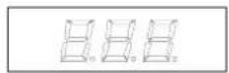
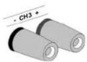
2. CH3 Independent Mode
Background / Connection The CH3 rating is 2.5 V / 3.3 V / 5 V, maximum 3 A. It works independently from CH1 and CH2, regardless of their modes.
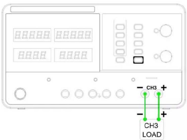
text_image
HHHHH HHHHH HHHHH CH3 + CH3 LOADOutput rating
Fixed 2.5 V / 3.3 V / 5 V, 3 A
No tracking Serial/Parallel mode
CH3 does not have tracking serial/parallel mode. Also, CH3 output is not affected by CH1 and 2 modes.
Panel operation
- Connect the load to the front panel CH3 +/- terminal.
- Select the output voltage from 2.5 V, 3.3 V and 5 V, using the CH3 voltage selector switch.
- To turn on the output, press the output key. The key LED turns on.
CC to CV

When the output Current level exceeds 3A, the overload indicator turns red and CH3 operation mode switches from Constant Voltage to Constant Current.
“Overload” in this case does not mean an abnormal operation.
Operation (contd.)
3. CH1/CH2 Tracking Serial Mode
Tracking series operation doubles the Voltage capacity of the power supply series by internally connecting CH1 (Master) and CH2 (Slave) in serial and combining the output to a single channel. CH1 (Master) controls the combined Voltage output level.
The following describes two types of configurations depending on the common ground usage.
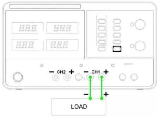
3.1 Tracking serial without common terminal
Connection
text_image
CH2 + CH1 + LOAD0 - 60 V / 0 - 3 A
Output rating
Panel operation

flowchart
graph TD
    A["Input"] --> B["FINE"]
    B --> C["CURRENT"]
    D["CH1"] --> E["VOLTAGE"]
    E --> F["CURRENT"]
-
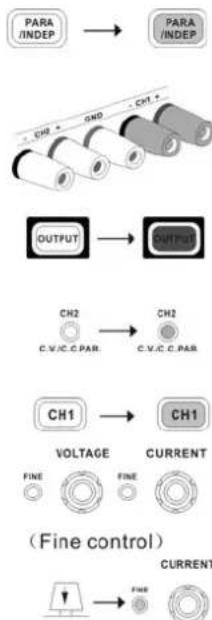
Press the SER/INDEP key to activate the tracking serial mode. The key LED turns on.
-
Connect the load to the front panel terminals, CH1+ & CH2-. (Single supply).
-
Press the CH2 switch (LED turns on) and use the Current knob to set the CH2 output current to the maximum level. By default, the Voltage and Current knob work in the coarse mode. To activate the fine mode, press the knob and turn on the FINE LED.
Coarse: 1V or 0.1A @ rotation click. Fine: the smallest digit @ rotation click.
- Press the CH1 switch (LED turns on) and use the Voltage and Current knob to set the output voltage and current level..
Operation (contd.)

-
To turn on the output, press the output key. The key LED turns on.
-
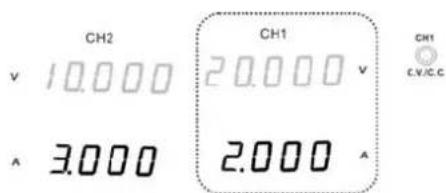
Refer to the CH1 (Master) meter and indicator
text_image
CH2 v 10.000 ^ 3.000 CH1 20.000 v 2.000 CH1 C.V.C.Cfor the output setting level and CV/CC status
Voltage level
Double the reading on the CH1 Voltage meter. In the above case, the actual output is 20.0 × 2 = 40.0V .
Current level
CH1 meter reading shows the output Current. In the above case, 2.000A. (CH2 Current control must be in the Maximum position=3.0A).
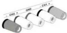
3.2 Tracking serial with common terminal
text_image
CH2 + CH1 + COM + LOADOutput rating
0 \~ 60 V / 0 \~ 3 A for CH1 \~ COM
Panel operation

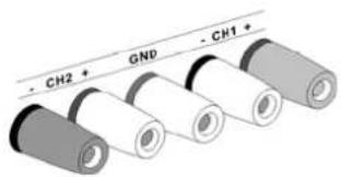
text_image
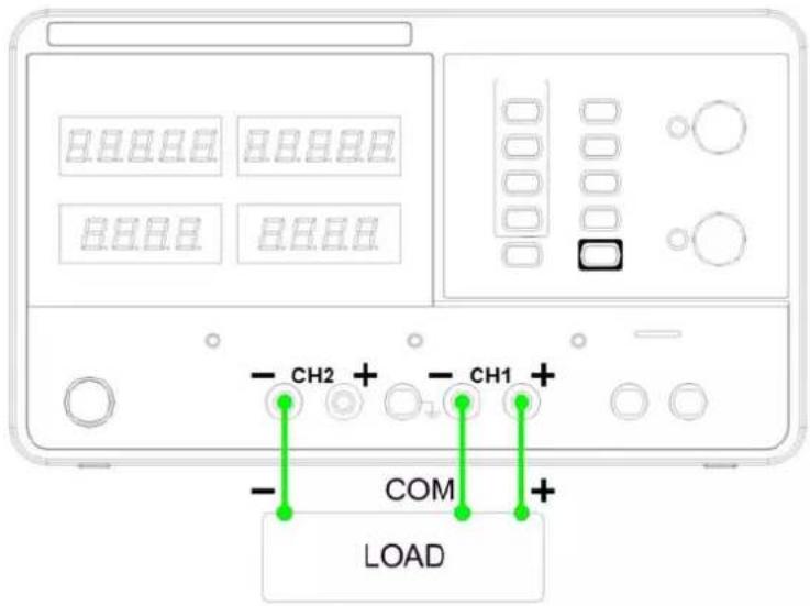
- CH2 + GND - CH1 +-
Press the SER/INDEP key to activate the tracking serial mode. The key LED turns on.
-
Connect the load to the front panel terminals, CH1+/- & CH2-. Use the CH1 (-) terminal as the common line connection.
-
Connect the load to the front panel terminals, CH1+/- & CH2-. Use the CH1 (-) terminal as the common line connection.
Operation (contd.)
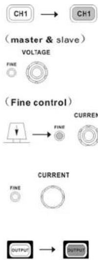
flowchart
graph TD
    A["CH1"] --> B["CH1"]
    C["master & slave"] --> D["VOLTAGE"]
    E["FINE"] --> F["FINE"]
    G["(Fine control)"] --> H["FINE"]
    I["CURRENT"] --> J["FINE"]
    K["CURRENT"] --> L["FINE"]
    M["OUTPUT"] --> N["OUTPUT"]
-
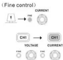
Press the CH1 switch (LED turns on) and use the Voltage knob to set the master & slave output voltage (the same level for both channels). By default, the Voltage and Current knob work in the coarse mode. To activate the fine mode, press the knob and turn on the FINE LED. Coarse: 1V or 0.1A @ rotation click. Fine: the smallest digit @ rotation click.
-
Use the current knob to set the master output current.
-
To turn on the output, press the output key. The key LED turns on.
-
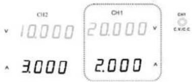
For the master (CH1) output level and CV/CC status, refer to the CH1 meter and indicator. Master (CH1) voltage level: CH1 meter reading shows the output voltage. In the above case, 20.0 V. Master (CH1) current level: CH1 meter reading shows the output current. In the above case, 2.000 A.
-
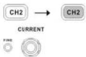
Press the CH2 switch (LED turns on) and use the Current knob to set the slave output current.
- For the slave (CH2) output level and CV/CC status, refer to the CH1/2 meter and CH2 indicator.
Master (CH1) voltage level: CH1 meter reading shows the output voltage. In the above case, 20.0 V.
Master (CH1) current level: CH1 meter reading shows the output current. In the above case, 2.000 A.
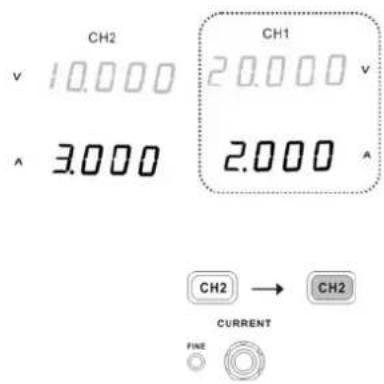
text_image
CH2 V 10.000 ^ 3.000 CH1 20.000 v 2.000 CH2 → CH2 CURRENT FINE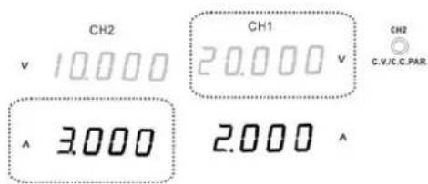
text_image
CH2 v 10.000 CH1 20.000 v ^ 3.000 2.000 ^ CH2 C.V./C.C.PAROperation (contd.)
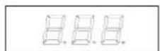
3.4 CH1 / CH2 Tracking Parallel Mode
Background / connection
Tracking parallel operation doubles the current capacity of the power supply by internally connecting CH1 and CH2 in parallel and combining the output to a single channel. CH1 controls the combined output.
text_image
HHH HHH HHH - CH2 + - CH1 + - + LOADOutput rating 0 - 30 V / 0 ≈ 6 A
Panel operation
flowchart
graph TD
    A["PARA /INDEP"] --> B["PARA /INDEP"]
    B --> C["OUTPUT"]
    C --> D["CH2"]
    D --> E["C.V.C.C.PAR"]
    E --> F["CH1"]
    F --> G["VOLTAGE"]
    G --> H["FINE"]
    G --> I["FINE"]
    F --> J["C.V.C.C.PAR"]
    J --> K["FINE"]
    L["(Fine control)"] --> M["FIRE"]
    M --> N["CURRENT"]
text_image
CH2 v 10.000 ^ 3.000 CH1 20.000 v 2.000 CH1 C.V./C.C- Press the PAR/INDEP key to activate the tracking parallel mode. The key LED turns on.
- Connect the load to the CH1 +/- terminals.
- To turn on the output, press the output key. The key LED turns on.
- The CH2 indicator turns red, indicating tracking parallel (PAR) mode
- Press the CH1 switch (LED turns on) and use the Voltage and Current knob to set the output voltage and current. The CH2 output control is disabled. By default, the Voltage and Current knob work in the coarse mode. To activate the fine mode, press the knob and turn on the FINE LED.
- For the output level and CV/CC status, refer to the CH1 meter and indicator.
Voltage level: The CH1 meter reading shows the output voltage. In the above case, 20.0 V.
Current level: Double the amount of CH1 current meter reading. In the above case,
$$ 2. 0 \mathrm{A} \times 2 = 4. 0 \mathrm{A} $$
Save / Recall Setup
| Save Setup | |
| Background | The front panel settings can be stored into one of the four internal memories. |
| Programming contents | The following list shows the programming setting contents:➢ Independent / tracking serial / tracking parallel mode➢ CH1/CH2 knob selection➢ Fine/coarse knob editing mode➢ Beeper on/off➢ Output voltage/current levelThe following settings are always saved as “off”:➢ Output on/off➢ Front panel lock on/off |
| Panel operation | Press one of the 1~4 Memory keys for 2 seconds, for example number 1. The panel settings will be saved in memory No.1 by long push to this key and the key LED turns on. When the panel settings are modified, the LED turns off.When the setting is stored, the output automatically turns off. |
| Recall Setup | |
| Background | The front panel settings can be recalled from one of the four internal memories. |
| Programming contents | The following list shows the programming setting contents:➢ Independent / tracking serial / tracking parallel mode➢ CH1/CH2 knob selection➢ Fine/coarse knob editing mode➢ Beep on/off➢ Output voltage/current levelThe following settings are always saved as “off”:➢ Output on/off➢ Front panel lock on/off |
| Panel operation | Press one of the 1~4 Memory keys, for example number 1. The panel settings saved in memory No.1 will be recalled by pressing this key. The key LED turns on. When the panel settings are modified, the LED turns off.When a setting is recalled, the output automatically turns off. |
Remote Control
| Remote Control Setup | |
| Background | The front panel settings can be recalled from one of the four internal memories. |
| Interface | USB slave port, rear panel |
| COM setting | Set up the COM port inside the PC according to the following list:Baud rate: 9600Parity bit: NoneData bit: 8Stop bit: 1Data flow control: None |
| Functionality check | Run this query command via the terminal application such as MTTTY (Multi-threaded TTY).*idn?This should return the identification information:Manufacturer, model name, serial number.Drivers for LV / LW programming are available on our website. |
Command Syntax
| Command format | ISET: | 1: command header | |
| 2: output channel | |||
| 3: separator | |||
| 4: parameter | |||
| Output channel | Type | Description | Example |
| Boolean logi | 0 (off), 1 (on) | ||
| Integers | 0, 1, 2, 3 | ||
| Decimal numbers | 0.1, 3.14, 8.5 | ||
| Output channel | 1 (CH1) or 2 (CH2) | ||
| Commands must be capital letters | |||
Remote Control (contd.)
| Error Messages | The following error messages might appear when the instrument cannot accept the command. |
| Program mnemonic too long | The command length must be 12 characters or less. |
| Invalid character | Invalid characters, such as symbols, are entered. Example: VOUT# |
| Too many digits | The command exceeded the maximum number of decimals: 3 digits. |
| Missing parameter | The parameter is missing from the command. Example: VSET: (should have a number) |
| Data out of range | The entered value exceeds the specification. Example: VSET:33 (should be : 32 V) |
| Command not allowed | The entered command is not allowed in the circumstance. Example: trying to set CH2 output while in the tracking mode. |
| Undefined header | The entered command does not exist, or the syntax is wrong. |
| Command list | Detailed descriptions of each command starts from the next page.The “HELP” command shows all the following commands and their meanings, except for the HELP command itself. |
| ISET::<NR2> | Sets the output current |
| ISET<X> | Returns the output current setting |
| VSET::<NR2> | Sets the output voltage |
| VSET | Returns the output voltage setting |
| IOUT<X> | Returns the actual output current |
| VOUT<X> | Returns the actual output voltage |
| TRACK<NR1> | Selects the operation mode |
| BEEP<BOOLEAN> | Turn on or off the output |
| LOCK<BOOLEAN> | Turn on or off the front panel lock |
| OUT<BOOLEAN> | Turn on or off the output |
| SATATUS | Returns the MODEL status |
| IDN | Returns the MODEL identification |
| RCL<NR1> | Recalls a panel setting |
| SAVE<NR1> | Saves the panel setting |
| HELP | Shows the command list |
Remote Control (contd.)
Command details
| Command | ISET: |
| Description Sets | the output current. |
| Panel operation | Refer to p. 11 |
| Response time | Min.70ms |
| Example | ISET1:2.234Sets the CH1 output current to 2.234A, |
| Command | ISET |
| Description Returns the output current setting | |
| Response time | Min.70ms |
| Example | ISET1Returns CH1 output current setting. |
| Command | VSET: |
| Description Sets | the output voltage. |
| Panel operation | Refer to p. 11 |
| Response time | Min.70ms |
| Example | VSET1:20.345Sets the CH1 voltage to 20.345V. |
| Command | VSET |
| Description Returns the output voltage setting. | |
| Response time | Min.80ms |
| Example | VSET1Returns the CH1 voltage setting. |
| Command | IOUT |
| Description Returns the actual output current. | |
| Response time Min.80ms | |
| Example | IOUT1Returns the CH1 output current. |
| Command | VOUT |
| Description Returns the actual output voltage. | |
| Response time | Min.70ms |
| Example | VOUT1Returns the CH1 output voltage. |
| Command | TRACK |
| Description Selects the operation mode: INDEP, tracking SER, tracking PAR | |
| Panel operation Refer to p. 11 | |
| NR1 | 0: Independent1: Tracking serial2: Tracking parallel |
| Response time Min.70ms | |
| Example | TRACK0Selects the independent mode. |
| Command | BEEP |
| Description Turns on or off the beeper. | |
| Panel operation Refer to page 10 | |
| Response time Min.70ms | |
| Example | BEEP1Turns on the beeper/ |
| Command | OUT |
| Description Turns on or off the output. | |
| Panel operation Refer to p. 5 | |
| Response time Min.70ms | |
| Example | OUT1Turns on the output. |
Remote Control (contd.)
Command details (contd).
| Command | LOCK |
| Description Turns on or off the front panel lock | |
| Panel operation | Refer to p. 11 |
| Response time | Min.70ms |
| Example | LOCK1Locks the front panel. |
| Command | STATUS |
| Description Returns the MODEL status. | |
| Response time Min.400ms | |
| Contents 8 bits in the following format.(Refer to table on the right.) | |
| Bit | Item | Description |
| 0 CH1 | 0=CC | mode, 1=CV mode |
| 1 CH2 | 0=CC | mode, 1=CV mode |
| 2,3 | Trac king | 00=Independent, 01=Tracking serial, 11=Tracking parallel |
| 4 | Beep | 0=Off, 1=On |
| 5 | Lock | 0=Lock, 1=Unlock |
| 6 | Output | 0=Off, 1=On |
| 7 | N/ | N/A |
| Command | RCL |
| Description Recalls a panel setting. | |
| Panel operation Refer to p. 18 | |
| NR1 1~4: Memory number 1 to 4 | |
| Response time Min.70ms | |
| Example | RCL1Recalls the panel setting stored in memory NO. 1. |
| Command | IDN |
| Description Returns the MODEL identification | |
| Response time Min.300ms | |
| Contents Manufacturer, model name, serial number | |
| Command | SAV |
| Description Saves the panel setting. | |
| Panel operation Refer to p. 18 | |
| NR1 1~4: Memory number 1 to 4 | |
| Reponse time Min.70ms | |
| Example | SAV1Stores the panel setting intomemory NO. 1. |
| Command | HELP |
| Description Shows the command list. | |
| Response time Min.1000ms | |
| Contents Refer to the following tale. | |
Remote Control (contd.)
Contents for Command Help
| ISET: | Sets the value of current. |
| VSET: | Sets the value of voltage. X: 1=CH1, 2=CH2. |
| ISET | Return the value of current. |
| VSET | Return the value of voltage. |
| IOUT | Returns actual output current. |
| VOUT | Returns actual output voltage. |
| TRACK | Sets the output of the power supply working on independent or tracking mode. NR1: 0=INDE, 1=SER, 2=PARA. |
| BEEP | Sets the BEEP state on or off. |
| LOCK | Sets the entry-key lock state on or off. |
| OUT | Sets the output state on or off |
| STATUS | Returns the power supply state. |
| bit0:(CH1)0=CC,1=CV | |
| bit1:(CH2)0=CC,1=CV | |
| bit23:(TRACK)10=DEP, 11=SER,01=PAR | |
| bit4:(BEEP)0=OFF,1=ON | |
| bit5:(LOCK)0=LOCK,1=UNLOCK | |
| bit6:(OUT)0=OFF,1=ON | |
| IDN | Returns instrument identification. |
| RCL | Recall the setting data from the memory which previous saved. |
| SAV | Saves the setting data to memory. |
| NR0: 1=Memory1, 2=Memory2, 3=Memory3, 4=Memory4; |
Technical Specifications
| Output ratings | CH1/CH2 independent: 0 ~ 30 V, 0 ~ 3 ACH1/CH2 serial: 0 ~ 60 V, 0 ~ 3 ACH1/CH2 parallel: 0 ~ 30 V, 0 ~ 6 ACH3: 2.5 V / 3.3 V / 5 V, 3 A |
| Constant voltage operation | Line regulation: ≤ 0.01 % + 3 mVLoad regulation: ≤ 0.01 % + 3 mVRecovery time: ≤ 100 us (50 % load change, minimum load 0.5 A)Ripple & Noise: ≤ 1 mVrmsTemp.co-efficient: ≤ 300 ppm |
| Constant current operation | Line regulation: ≤ 0.2 % + 3 mALoad regulation: ≤ 0.2 % + 3 mARippe & Noise: ≤ 3 mArms |
| Tracking parallel operation | Line regulation: ≤ 0.1 % + 3 mVLoad regulation: ≤ 0.01 % + 5 mVTracking error: ≤ 0.05 % + 50 mV of Master (no load) |
| Tracking serial operation | Line regulation: ≤ 0.01 % + 5 mVLoad regulation: ≤ 300 mVPositive and negative supply: Slave tracking error: ≤ 0.5 % + 10 mV of the master (No load. With load, add load regulation ≤ 300 mV) |
| CH3 output | Line regulation: ≤ 25 mVLoad regulation: ≤ 25 mVRipple & Noise: ≤ 2 mV rmsOutput voltage: 2.5 V, 3.3 V, 5 V (selectable), ± 8 %Output current: 3 A |
| Display | Ammeter: 3.20 A full scale, 3 D 0.5" LED displayVoltmeter: 32.0 V full scale, 3 D 0.5" LED displayVoltmeter resolution: 100 mVAmmeter resolution: 10 mAProgramming accuracy: ±(0.5 % of reading + 2D), ±(0.5 % of reading + 2D)Readback accuracy: ±(0.5 % of reading + 2D), ±(0.5 % of reading + 2D) |
| Protection | Over voltage, over current, over load, over temperature, current limit, short circuit and reverser polarity protections. |
| Insulation | Between base and output terminal ≥ 20 MΩ / 500 VDCBetween base and power cord ≥ 30 MΩ/ 500 VDC |
| Operation environment | Indoor useAltitude: ≤ 2000mAmbient temperature: 0 ~ 40°Relative humidity: ≤ 80 %Installation category: IIPollution degree: 2 |
| Storage environment | Ambient temperature: -10 ~ 70°Relative humidity: ≤ 70 % |
| Power source | AC 110 V / 220 V ± 10 %, 50 / 60 Hz, 500 VA- CAT II |
Mechanical Specifications
Dimensions
- User manual × 1
- Power cord × 1
• LV and LW Drivers available on Site Internet - USB cable