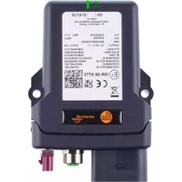
CR3171 - IoT gateway IFM - Free user manual and instructions
Find the device manual for free CR3171 IFM in PDF.


User questions about CR3171 IFM
0 question about this device. Answer the ones you know or ask your own.
Ask a new question about this device
Download the instructions for your IoT gateway in PDF format for free! Find your manual CR3171 - IFM and take your electronic device back in hand. On this page are published all the documents necessary for the use of your device. CR3171 by IFM.
USER MANUAL CR3171 IFM
Operating instructions mobileIoT gateway
CR3171
Contents
1 Preliminary note 3
1.1 Symbols used 3
1.2 Warnings.... 3
1.3 Manufacturer / Distributor 3
2 Safety instructions.... 4
2.1 Cyber security 5
2.2 Air traffic 5
3 Intended use.... 6
4 Function 7
4.1 WiFi frequencies and channels 7
4.2 Mobile radio interface 7
4.3 eSIM card 8
4.4 Connection modes 8
4.4.1 Remote access 8
4.4.2 Cloud connection 8
4.5 Input/output functions 8
4.6 Accelerometers and gyro sensors.... 9
4.7 GNSS (global navigation satellite system).... 9
4.7.1 GNSS multicast.... 9
5 Installation.... 11
5.1 Mounting the antennas 11
6 Electrical connection.... 12
6.1 Connectors 12
6.1.1 Operating voltage, CAN interface, inputs and outputs.... 12
6.1.2 GNSS antenna connection 12
6.1.3 GSM antenna connection 13
6.1.4 Ethernet port 13
7 Light indicators 14
7.1 ON LED 14
7.2 STATUS LED 14
8 Set-up.... 15
8.1 Necessary components.... 15
8.2 Connect the unit 15
8.3 Device configuration via the web interface 15
8.4 Factory reset.... 16
9 Repair, maintenance and disposal 17
Glossary 18
1 Preliminary note
You will find instructions, technical data, approvals and further information using the QR code on the unit / packaging or at documentation.ifm.com.
1.1 Symbols used
√ Requirement
Instructions
Reaction, result
[...] Designation of keys, buttons or indications
→ Cross-reference

Important note
Non-compliance may result in malfunction or interference.

Information
Supplementary note
1.2 Warnings
Warnings indicate the possibility of personal injury and damage to property. This enables safe product handling. Warnings are graded as follows:

WARNING
Warning of serious personal injury
▷ If the warning is not observed, fatal and serious injuries are possible.

CAUTION
Warning of minor to moderate personal injury
▷ If the warning is not observed, minor to moderate injuries are possible.
ATTENTION
Warning of damage to property
▷ If the warning is not observed, damage to property is possible.
1.3 Manufacturer / Distributor
Manufacturer: Proemion GmbH
Distributor: ifm electronic gmbh
2 Safety instructions
- The unit described is a subcomponent for integration into a system.
- The system architect is responsible for the safety of the system.
-
The system architect undertakes to perform a risk assessment and to create documentation in accordance with legal and normative requirements to be provided to the operator and user of the system. This documentation must contain all necessary information and safety instructions for the operator, the user and, if applicable, for any service personnel authorised by the architect of the system.
-
Read this document before setting up the product and keep it during the entire service life.
- The product must be suitable for the corresponding applications and environmental conditions without any restrictions.
- Only use the product for its intended purpose (→ Intended use).
- If the operating instructions or the technical data are not adhered to, personal injury and/or damage to property may occur.
- The manufacturer assumes no liability or warranty for any consequences caused by tampering with the product or incorrect use by the operator.
• Installation, electrical connection, set-up, programming, configuration, operation and maintenance of the product must be carried out by personnel qualified and authorised for the respective activity. - Protect units and cables against damage.
- Replace damaged units, otherwise the technical data and safety will be impaired.
- Observe applicable documents.

WARNING
Overload damage due to malfunctions.
▷ Risk of serious or fatal injuries.
▶ To limit the power in the event of a malfunction, protect the DC power supply circuit with an external fuse with a maximum rating of 2 A during installation.
ATTENTION
Water ingress
▷ Damage to the device
▷ The device has been tested against water jets in accordance with IPxK5 of the ISO 20653 standard. Other loads, e.g. with a high-pressure cleaner or a higher flow rate, do not correspond to the intended use.
▷ Never clean the appliance with a high-pressure cleaner or the like.
Interference with electronic devices due to high-frequency energy.
Do not use the device with damaged cables or connectors. Cables and connectors must always be screened.
Observe all radio regulations. Disconnect the power supply to the device if its use is prohibited or if its operation may cause faults or hazards.
The horizontal distance between the antennas can be calculated for each radio signal. The distance between two antennas should always be greater than 1/4 of the wavelength, but not a multiple of the wavelength. If you use several antennas with different radio signals, the distance of the antenna with the lowest frequency range must be observed.
GNSS:
frequency range 1.559 GHz, wavelength 19.23 cm (1/4 = 4.8 cm)
Bluetooth:
frequency range 2.400 - 2.4835 GHz, wavelength 12.49 cm (1/4 = 3.12 cm)
WiFi:
- frequency range 2.400 - 2.4835 GHz, wavelength 12.49 cm (1/4 = 3.12 cm)
- frequency range 5.150 - 5.725 GHz, wavelength 5.17 cm (1/4 = 1.29 cm)
Example: When using a GNSS antenna and a WiFi antenna, the distance between the two antennas should be at least 4.8 cm. The distances 19.23 cm, 12.49 cm and multiples of these values should be avoided.
2.1 Cyber security
ATTENTION
Operating the machine in an unprotected network environment
▷ Unauthorised read or write access to data is possible.
▷ Unauthorised manipulation of the device function is possible.
▶ Check and restrict access options to the device.
2.2 Air traffic
The device must not be operated on board aircraft.
Using it in an aircraft can affect the navigation and communication systems. An offence can lead to legal action against the offender.
3 Intended use
The device transmits data of a vehicle or machine via Ethernet or wirelessly. It supports 2G, 3G and 4G mobile radio standards.
The device meets the requirements of protection class IP xK5 and is suitable for use in relevant environments. (With mounted connectors or protective caps: IP 6K7).
Only use the unit within the limits of the technical data. → Technical data.

Notes relevant for approval: Package insert of the device and documentation.ifm.com
4 Function
The device enables wireless data transmission in various operating modes.
| Function | CR3171 |
| Antenna | external |
| Mobile communications | 4G worldwide (certified countries only) |
| Real-time mode | ● |
| Cloud logging mode | ● |
| Input/output functions | 3/1 |
| Acceleration sensor | ● |
| Gyro sensor | ● |
| Buffer battery for real-time clock (RTC) | >48 h |
| GNSS | ● |
| ifm e-SIM | ● |
- = applicable
4.1 WiFi frequencies and channels
The WiFi interface of the features automatic domain detection and supports the following regulatory domains: WORLD, ETSI, FCC. If neither ETSI nor FCC are recognised, the radio module uses WORLD as the standard.
| Name | Band | TX Channel |
| World | 2.4 GHz | 1, 2, 3, 4, 5, 6, 7, 8, 9, 10, 11 |
| U-NII-1 | 36, 40, 44, 48 | |
| U-NII-2 | 52, 56, 60, 64 | |
| U-NII-2e | 100, 104, 108, 112, 116, 132, 136, 140 | |
| U-NII-3 | - | |
| ETSI | 2.4 GHz | 1, 2, 3, 4, 5, 6, 7, 8, 9, 10, 11, 12, 13 |
| U-NII-1 | 36, 40, 44, 48 | |
| U-NII-2 | 52, 56, 60, 64 | |
| U-NII-2e | 100, 104, 108, 112, 116, 120, 124, 128, 132, 136, 140 | |
| U-NII-3 | 149, 153, 157, 161, 165 | |
| FCC | 2.4 GHz | 1, 2, 3, 4, 5, 6, 7, 8, 9, 10, 11 |
| U-NII-1 | 36, 40, 44, 48 | |
| U-NII-2 | 52, 56, 60, 64 | |
| U-NII-2e | 1O0, 104, 108, 112, 116, 132, 136, 140 | |
| U-NII-3 | 149, 153, 157, 161, 165 |
If a WiFi channel is used that is not available in the recognised domain, communication may be disrupted.
4.2 Mobile radio interface
The device has a mobile radio interface for mobile data transmission.
The device supports the 2G, 3G and 4G mobile networks.
The device detects the mobile network with the best transmission speed and automatically switches to it. The mobile radio interface supports bidirectional data exchange in the mobile network.
4.3 eSIM card
The unit is equipped with an embedded SIM (eSIM) card. The eSIM card is delivered with an eSIM profile that contains all the necessary communication settings.

The eSIM card of the unit is not activated on delivery. After registering the unit, activation of the eSIM card can take up to 4 hours.
4.4 Connection modes
The device can be operated in the following connection modes:
- Remote access
- Cloud connection
4.4.1 Remote access
This function allows remote access to the CR3171 and other devices on the Ethernet network, for example for troubleshooting or maintenance purposes.
The remote access function has the following features:
- Secure remote connection: The established connection has robust encryption and secure authentication mechanisms that protect data in transit and allow only authorised users to interact with the machine or application.
- Troubleshooting and support: Remote access enables efficient problem diagnosis and troubleshooting without the need to be physically present at the machine site.
- Remote desktop and management: Administrators and maintenance technicians are given the ability to remotely manage machines from a central location. They can display and control the visualisations embedded in the machine's HMI interface.
4.4.2 Cloud connection
The device can be integrated into ifm's mobile machine cloud. This connection is used for the bidirectional transfer of data between the cloud and the machine.
The cloud connection includes the following functionalities:
- Data acquisition: machine data and process information are transferred to the cloud. The data is processed and stored so that it can be made available to authorised persons or users via an online connection.
- Machine management: cloud connectivity allows users to perform comprehensive machine management tasks, such as configuration and provision of software or firmware updates.
4.5 Input/output functions
The device has additional input/output functions (3 analogue inputs, 1 digital output). For example, the input function can be used to collect device or machine status information or to directly detect and monitor switch states. The data determined via the input/output functions can be visualised or transferred via the CAN bus.
4.6 Accelerometers and gyro sensors
The accelerometers measure acceleration along the X, Y and Z axes. The 3-axis gyro sensor determines the angular velocity on the X, Y and Z axes. This data is evaluated and can be forwarded to the controller via CAN bus.

4.7 GNSS (global navigation satellite system)
The device has a GNSS receiver. The device can transmit position data determined by the GNSS receiver to the cloud via Ethernet, WLAN or the mobile network.
The device can evaluate signals from GPS, GLONASS, Galileo and BeiDou satellites. Data from two navigation systems can be evaluated simultaneously. This enhances the accuracy.
GNSS configuration: Device configuration via the web interface ( → ☐ 15)
4.7.1 GNSS multicast
The GNSS position data is sent from the device using multicasting. To receive this position data, the multicast stream must be monitored. The GNSS position data is transmitted using the NMEA standard. This data contains the NMEA data sets GPGGA and GPRMC.

Default settings for GNSS multicast on the gateway:
Multicast IP address: 239.255.46.9
Multicast Port: 31514
Examples of NMEA data:
- GPGGA
\$GPGGA,123519,4807.038,N,01131.000,E,1,08,0.9,545.4,M,46.9,M,,*47
| Content | Field | Description |
| $GPGGA, | Data set name (GPGGA) | Indicates that this is a data set with GPS fix data. |
| 123519, | UTC time | Time of the recorded GPS fix (HHMMSS. SS). |
| 4807.038, | Latitude | Latitude of the position (DDMM. MMMM). |
| N, | N/S Indicator | North (N) or south (S) of the equator. |
| 01131.000, | Longitude | Longitude of the position (DDDMM. MMMM). |
| E, | E/W Indicator | East (E) or west (W) of the prime meridian. |
| 1, | GPS fix quality | Quality of the GPS fix (0, 1 or 2). |
| 08, | Number of satellites | Number of satellites used for the GPS fix. |
| 0.9, | Horizontal deviation | Measure of horizontal accuracy (HDOP – Horizontal Dilution of Precision). |
| 545.4, | Height | Height above sea level (in metres). |
| M, | Unit for the height | Unit for the height (M for metre). |
| 46.9, | Geoidal separation | Height difference between ellipsoid and geoid (in metres). |
| M, | Unit for geoidal separation | Unit for geoidal separation (M for metre). |
| , | Age of the DGPS data set | Age of the differential GPS data (if available). |
| , | DGPS reference station | ID of the station providing differential corrections. |
| * | End of data set marker | Marks the end of the data set. Separates the data set from the check-sum. |
| 47 | Checksum | Checksum for data security. |
• GPRMC
\$GPRMC,123519,A,4807.038,N,01131.000,E,022.4,084.4,230394,003.1,W*6A
| Content | Field | Description |
| $GPRMC, | Data set name (GPRMC) | Indicates that these are recommended minimum specific GPS/transit data. |
| 123519, | UTC time | Time of the recorded GPS fix (HHMMSS. SS). |
| A, | Status | A: valid dataV: invalid data |
| 4807.038, | Latitude | Latitude of the position (DDMM. MMMM). |
| N, | N/S Indicator | North (N) or south (S) of the equator. |
| 01131.000, | Longitude | Longitude of the position (DDDMM. MMMM). |
| E, | E/W Indicator | East (E) or west (W) of the prime meridian. |
| 022.4, | Speed over ground | Speed over ground (in knots). |
| 084.4, | Course over ground | Course or direction of movement (in degrees). |
| 230394, | UTC date | Date in DDMMYY format. |
| 003.1, | Magnetic variation | Magnetic variation (in degrees, positive for east, negative for west). |
| W | E/W Indicator for magnetic variation | Indicates whether there is an easterly (E) or westerly (W) magnetic variation. |
| * | End of data set marker | Marks the end of the data set. Separates the data set from the checksum. |
| 6A | Checksum | Checksum for data security. |

Each NMEA data set ends with the character string \r\n (0x0A, 0x0D).
5 Installation

▶ Disconnect the power of the machine before installation.

The device must be installed in a horizontal position. Installation with the connectors facing upwards or downwards is not permitted.
The device must be fixed with the rear facing the mounting surface.
ATTENTION
Higher impact stress > IK07
▷ Damage possible
▷ Protection rating and electrical protection might be impaired
▷ Risk of injury possible
▶ If necessary, the system creator must take external measures to protect the device depending on the requirements of the corresponding application.
▶ Replace damaged devices, otherwise the technical data and safety will be impaired.

Fig. 1: Holes for mounting
▶ Use 2 M5x30 cylinder head bolts to fix the device on an even surface. Tightening torque: 2.2 Nm
5.1 Mounting the antennas
▶ When mounting the antennas in vehicles avoid the vicinity of fuel tanks, vessels with explosives or insufficiently screened electronic components ( → 2 Safety instructions).
▶ Position the antennas so that a permanent distance of min. 0.2 m from people is ensured during operation.
- ▶ Do not install the antennas in closed metal constructions such as the driver's cab.
▶ To reliably receive the GPS signals, position the GPS antenna with unrestricted access to the sky.
▶ Please observe the antenna manufacturer's notes.

Stable data transmission requires a good antenna signal. In case of problems change the position of the antennas or the mobile equipment if necessary.

A loosely tightened antenna connector also causes signal loss.
6 Electrical connection
6.1 Connectors
Use only IP 6K7 rated connectors to ensure protection class IP 6K7.

1: Micro Timer II connector, 14 pins (CAN, supply, inputs, outputs)
2: M12 Ethernet socket, D-coded
3: FAKRA connector, D-coded
4: FAKRA connector, C-coded
6.1.1 Operating voltage, CAN interface, inputs and outputs
The analogue inputs operate in a range of 0...15 V. Optionally, the input can be used as a digital input with a maximum voltage of 36 V DC.
The digital output switches the supply voltage on terminal 30. The maximum load is 500 mA. If this limit value is not guaranteed by the external power supply of terminal 30, external protection must be provided.
The input terminal 15 detects a high signal from a voltage of 5.5 V and a low signal at a voltage < 2.3 V.

Fig. 2: Micro Timer II connector, 14-pin
1: VCC / terminal 30 (supply)
2: CAN3_L (CAN interface 3 (low) bidirectional)
3: GND / terminal 31 (supply)
4: Analogue input 1
5: Analogue input 2
6: Analogue input 3
7: Digital output
8: Digital input / terminal 15 (input, ignition signal)
9: CAN3_H (CAN interface 3 (high) bidirectional)
10: CAN2_GND
11: CAN2_H (CAN interface 2 (high) bidirectional)
12: CAN2_L (CAN interface 2 (low) bidirectional)
13: CAN1_H (CAN interface 1 (high) bidirectional)
14: CAN1_L (CAN interface 1 (low) bidirectional)
6.1.2 GNSS antenna connection
The GNSS antenna connection is supplied with a voltage of approx. 3.3 V and can supply active antennas with a maximum current of 40 mA. The connection is short-circuit-proof and detects that an antenna is present when the current is greater than approx. 2 mA.
Make sure that the unit is switched off during installation.

Fig. 3: FAKRA connector, C-coded
1: Signal — GNSS signal, supply voltage 3.3 V
2: GND — shielding / housing
6.1.3 GSM antenna connection

Fig. 4: FAKRA connector, D-coded
1: Signal — mobile radio
2: GND — shielding / housing

The unit detects an antenna if it has a built-in diagnostic resistor (10 kΩ).
6.1.4 Ethernet port
The device is connected to the network via the Ethernet port.

1: TxD+
2: RxD+
3: TxD-
4: RxD-
On the device side, the screen must be connected to the metal thread of the M12 connector. On the other side, the screen must be connected to GND.
The threaded connections in the device correspond to the M12 standard. To ensure compliance with the specified protection rating, only cables that comply with this standard may be used. In the case of self-assembled cables, the system manufacturer is responsible for the protection rating.
▶ During installation, place the connectors vertically so that the coupling nut will not damage the thread.
▶ Observe the coding of the connectors during installation.
▶ Tighten the cable plug using 0.6 Nm.
7 Light indicators

1: ON LED
2: STATUS LED
7.1 ON LED
The ON LED indicates the status of the power supply.
| Colour | State | Meaning |
| - | Off | Device switched off or in sleep mode |
| White | On | Device starts (e.g. after applying the supply voltage) |
| Blue | Flashing | Device booting |
| Green | On | Device switched on, terminal 30 voltage in permissible range |
| Green | Flashing | The device performs an update while it is supplied with voltage via terminal 30. |
| Yellow | Flashing | The device performs an update while it is supplied with voltage via the internal battery. |
Tab. 1: ON LED
7.2 STATUS LED
The STATUS LED indicates the operating status of the active connections. The different colours are displayed according to priority, from 5 (low) to 1 (high). If several operating states are active at the same time, the STATUS LED always indicates the state with the highest priority.
| Colour | State | Priority | Meaning |
| - | Off | 0 | If the ON LED is also off:The devices is switched off. |
| White | On | 0 | Device starts (e.g. after applying the supply voltage) |
| Green | Flashing | 1 | The device initialises the interfaces and services. |
| Red | Flashing | 2 | Error |
| Blue | On | 3 | The device performs diagnostics. |
| Green | On | 4 | Device in normal operating mode. |
Tab. 2: STATUS LED
8 Set-up
8.1 Necessary components
The following components are needed to configure and set up the device:
- Hardware
- CR3171
- suitable antenna / combined antenna for navigation and radio (art. no.: EC3158)
- Connection cable (art. no.: EC3146 or EC3148)
– voltage supply 8...32 V DC - PC
– for further configuration (optional):
Ethernet connection cable with M12/RJ45 connector (e.g. art. no: EVF549)
- ifm mobileIoT Suite
To register and activate the device, access to the mobileIoT suite is required. You will receive the access data from your local ifm contact. The documentation for the mobileIoT Suite and for activating the device can be found in the mobileIoT Suite.
After you have activated the device, a mobileIoT data contract is concluded.
After successful registration and activation, the device establishes a connection to the ifm mobileIoT data portal and enables bidirectional data transfer.
8.2 Connect the unit
▶ Connect the GNSS and radio antennas to the device.
▶ Connect the Ethernet connection cable with the M12/RJ45 connector to the device and then connect it to the PC.
▶ Apply the supply voltage.
8.3 Device configuration via the web interface
The device has a local web server with a web interface that allows remote maintenance to configure the network interface and device settings via the HTTP(S) protocol.

The default IP address of the device is as follows: 192.168.82.1
▶ Ensure that the device is accessible in the network.
A connection is possible either via the Ethernet port or via WLAN.
▶ Ensure that a PC or similar device with a browser installed is available in the same network.
▶ Start the browser on a device (e.g. PC) in the corresponding network and call up the following URL: https://192.168.82.1
▶ Enter user name and password in the login dialogue.
User name: admin
The initial password is the MAC address of the device which is indicated on the type label of the device.
▷ The browser displays the web interface.
▶ Change the password in the [Security] section.
▶ Adjust the network configuration in the [Network] section.
The GNSS configuration is made in the [Location] section:
▶ Activate [Positioning service (GNSS)] to start the position determination.
▷ [GLONASS service], [BeiDou service] and [Galileo service] are configurable.
▶ Activate the required GNSS services.
If GNSS data is to be transmitted via Ethernet/IP:
▶ Activate [Multicasting preferences] and configure the corresponding IP address.
8.4 Factory reset
A reset button is located under pin 7 in the 14-pin Micro Timer II connector.

1: Reset button
▶ Press and hold the reset button for > 30 seconds.
▷ All settings are reset to the factory settings.
9 Repair, maintenance and disposal
The unit is maintenance-free.
▶ Contact ifm in case of malfunction.
▶ Do not open the housing as the unit does not contain any components which can be maintained by the user. The unit must only be repaired by the manufacturer.
▶ Clean the device using a dry cloth.
▶ Dispose of the unit in accordance with the national environmental regulations.
Glossary
GNSS
Global navigation satellite system, system for location tracking and navigation
mobileIoT data contract
Contract required for the mobile radio connection between the mobileIoT gateway and the mobileIoT server
mobileIoT data portal
Portal that processes/applies the data
mobileIoT platform
The complete cloud solution including backend (mobileIoT server), infrastructure, frontend for the machine management portal (mobileIoT suite) and data processing portal (mobileIoT data portal)
mobileIoT server
Cloud server on which the metrics are stored and to which the mobileIoT gateways connect
mobileIoT suite
Machine management portal
- 1 PRELIMINARY NOTE
- 1.1 SYMBOLS USED
- 1.2 WARNINGS
- 1.3 MANUFACTURER / DISTRIBUTOR
- 2 SAFETY INSTRUCTIONS
- 2.1 CYBER SECURITY
- 2.2 AIR TRAFFIC
- 3 INTENDED USE
- 4 FUNCTION
- 4.1 WIFI FREQUENCIES AND CHANNELS
- 4.2 MOBILE RADIO INTERFACE
- 4.3 ESIM CARD
- 4.4 CONNECTION MODES
- 4.4.1 REMOTE ACCESS
- 4.4.2 CLOUD CONNECTION
- 4.5 INPUT/OUTPUT FUNCTIONS
- 4.6 ACCELEROMETERS AND GYRO SENSORS
- 4.7 GNSS (GLOBAL NAVIGATION SATELLITE SYSTEM)
- 4.7.1 GNSS MULTICAST
- 5 INSTALLATION
- 5.1 MOUNTING THE ANTENNAS
- 6 ELECTRICAL CONNECTION
- 6.1 CONNECTORS
- 6.1.1 OPERATING VOLTAGE, CAN INTERFACE, INPUTS AND OUTPUTS
- 6.1.2 GNSS ANTENNA CONNECTION
- 6.1.3 GSM ANTENNA CONNECTION
- 6.1.4 ETHERNET PORT
- 7 LIGHT INDICATORS
- 7.1 ON LED
- 7.2 STATUS LED
- 8 SET-UP
- 8.1 NECESSARY COMPONENTS
- 8.2 CONNECT THE UNIT
- 8.3 DEVICE CONFIGURATION VIA THE WEB INTERFACE
- 8.4 FACTORY RESET
- 9 REPAIR, MAINTENANCE AND DISPOSAL
Brand : IFM
Model : CR3171
Category : IoT gateway