MX 675 - Measuring equipment METRIX - Free user manual and instructions
Find the device manual for free MX 675 METRIX in PDF.

| Product type | Dual display clamp multimeter |
| Brand | Metrix |
| Model | MX 675 |
| Dimensions | 257 x 80 x 43 mm |
| Weight | 440 g (with battery) |
| Power supply | 9 V alkaline battery (NEDA 1604, 6F22) |
| Typical battery life | 30 hours (MX675, without buzzer or backlight) |
| Display | Dual display LCD, 4 digits, max 9999 counts |
| Max jaw opening | 40 mm |
| Protection rating | IP30 |
| Electrical safety | CAT IV 600 V / CAT III 1000 V, double insulation, IEC 61010 |
| Voltage measurements | AC/DC up to 1400 V (DC) / 1000 V (AC TRMS) |
| Current measurements | AC/DC up to 1400 A (DC) / 1000 A (AC TRMS) |
| Resistance measurement | Up to 1000 Ω, accuracy 1% ± 3 counts |
| Continuity test | Buzzer for R < 35 Ω |
| Temperature measurement | -40°C to +1200°C (K-type thermocouple probe) |
| Frequency measurement | On AC voltage or current |
| Special functions | MIN/MAX, PEAK (1 ms), HOLD, DC Zero, Auto-off, Backlight |
| Maintenance and cleaning | Damp cloth with soapy water; no solvents |
| Repair and warranty | 1 year warranty; repair by Manumesure authorized technical centers |
Frequently Asked Questions - MX 675 METRIX
User questions about MX 675 METRIX
0 question about this device. Answer the ones you know or ask your own.
Ask a new question about this device
Download the instructions for your Measuring equipment in PDF format for free! Find your manual MX 675 - METRIX and take your electronic device back in hand. On this page are published all the documents necessary for the use of your device. MX 675 by METRIX.
USER MANUAL MX 675 METRIX
natural_image
Two digital clamp meters with yellow hangers and digital displays, placed on a plain surface (no visible text or symbols)FRANCAIS
ENGLISH
DEUTCH
ITALIANO
ESPAGNOL
1.1 Déballage - Emballage
text_image
Technical diagram of two digital multimeters with labeled parts and display screen, showing measurement ranges and function buttons.natural_image
Illustration of a digital multimeter connected to a wall-mounted power supply (no text or symbols visible)text_image
Diagram of a multimeter measuring 12V with a connected clamp and probe, showing measurement scale and connections.text_image
Diagram showing a multimeter connected to an electrical circuit with labeled components and wiringnatural_image
Illustration of a digital clamp meter with a 1500Ω power supply and two connected probes (no text or symbols visible)text_image
Diagram of two identical analog multimeters with labeled probes and dials, showing measurement setup for reading.text_image
120.0 600text_image
Diagram of a digital clamp meter with labeled scale and pointer, showing measurement ranges and wiring connections.Indication de surcharge: 1000 Veff
Indication de surcharge: 1400 ADC
Indication de surcharge : 1000 Aeff
5.2.5 Résistance (Ω)
| Gamme | Étendue de mesure | Résolution | Précision |
| 1000 Ω | 0.0 to 999.9 Ω | 0,1 Ω | 1% ± 3cls |
| 10000 Ω | 1000 to 9999 Ω | 1 Ω | 3.3 Vdc(Vmax) |
Protection: 1 000 Veff
5.2.6 Continuité
Protection: 1 000 Vrms
5.2.7 Fréquence Hz
- Pour les intensités
| Gamme | Etendue de mesure | Résolution | Précision | Sensibilité |
| 1000Hz | 0.0 to 999.9 Hz | 0.1 Hz | 1.0% ± 2 cts | 3 Aeff |
| 10000Hz | 1000 to 9999 Hz | 1 Hz |
- Pour les tensions
| Gamme | Etendue de mesure | Résolution | Précision | Sensibilité |
| 1000Hz | 0.0 to 999.9 Hz | 0.1 Hz | 1.0% ± 2 cts | 5 Veff |
| 10000Hz | 1000 to 9999 Hz | 1 Hz |
Stockage: -10^ to 60^ , < 80 % RH
5.5.2 Altitude
natural_image
Technical line drawing of a handheld electronic device with internal components (no text or symbols)6.2 Nettoyage
1.1 UNPACKING-PACKING 21
1.2 PRECAUTIONS AND SAFETY IN MEASUREMENTS......21
2 DESCRIPTION OF THE INSTRUMENT....23
2.1 DESCRIPTION OF THE FRONT PANEL 23
2.2 DESCRIPTION OF LCD DISPLAY....24
3 GENERAL DESCRIPTION 25
3.1 CORRECTION OF ZERO IN DC MEASUREMENT....25
3.2 HOLD FUNCTION - FREEZE DISPLAY....25
3.3 AUTOMATIC RANGES 25
3.4 AUTO POWER-OFF 25
3.5 PEAK FUNCTION (1 MS)....25
3.6 MAX MIN FUNCTION (500 MS)....26
3.7 BACKLIGHT FUNCTION 26
3.8 DISPLAY FUNCTION 26
4 OPERATION....26
4.1 AC VOLTAGE MEASUREMENT....26
4.2 DC VOLTAGE MEASUREMENT....27
4.3 MEASURING AC CURRENT 27
4.4 DC CURRENT MEASUREMENT (MX675 ONLY)......28
4.5 RESISTANCE MEASUREMENT AND AUDIO CONTINUITY
TEST 28
4.6 °C/°F TEMPERATURE MEASUREMENT .....29
4.7 MEASUREMENT OF VOLTAGE FREQUENCY....30
4.8 MEASUREMENT OF AC CURRENT FREQUENCY....30
5 TECHNICAL SPECIFICATIONS 31
5.1 GENERAL 31
5.2 CHARACTERISTICS 31
5.3 ELECTRICAL SAFETY (AS PER NF EN 61010):......32
5.4 GENERAL INFORMATION....33
5.5 ENVIRONMENTAL CONDITIONS....33
6 MAINTENANCE....34
6.1 REPLACING THE BATTERY 34
6.2 CLEANING 35
6.3 STORAGE 35
6.4 METROLOGICAL VERIFICATION 35
6.5 REPAIRS UNDER GUARANTEE AND OUTSIDE GUARANTEE35
7 WARRANTY....35
Thank you for purchasing this MX670 or MX675 series multimeter clamp.
To obtain the best service from your unit:
- read these operating instructions carefully,
- comply with the precautions for use.
1 GENERAL INSTRUCTIONS
If the device is used in a manner unspecified in these instructions, the protection provided by the device may be compromised.
1.1 Unpacking – Packing
All instruments are checked mechanically and electronically before shipment. All precautions are taken to be sure you receive an undamaged instrument. If there is damage, notify the carrier immediately.
1.2 Precautions and safety in measurements
1.2.1 Before any use
The MX670 & MX675 are dual display multimeter clamps. These multimeter clamps are compliant with electrical standard IEC 61010 concerning measuring instruments. For your own safety and to prevent any damage to your measuring instrument, you must follow the instructions in this manual.
* This instrument can be used for measurement on category IV electrical installations, in a degree 2 pollution environment, indoors at an altitude lower than 2000 m and with a voltage in relation to ground lower than or equal to 600 V.
* Definition of installation categories (see IEC 61010-1):
CAT I: Circuits not directly connected to network and specially protected.
Example: protected electronic circuits
CAT II: Circuits connected directly to low-voltage installation
Example: power supply for domestic electrical appliances and portable tools
CAT III: Power supply circuits in the building installation
Example: Electrical panel, circuit breakers, fixed industrial machines or devices
CAT IV: Source circuits of building low-voltage installation.
Example: Power feeders, counters and protection systems
For safety reasons, you must use only measuring leads, of voltage and category at least equal to those of the instrument and compliant with standard IEC 61010.
Before use, always check the integrity of the instrument casing and cable insulation.
1.2.2 Meaning of symbols used
| Symbol | Meaning |
| [4A10] | Instrument protected by double isolation. |
| ~ | Alternating current. |
| [26C7] | Direct current. |
| [7816] | CAUTION - DANGER! Refer to the operating manual. |
| [1446C] | Caution, risk of electrical shock |
| [CX09] | Audible continuity test |
 | Clamp: Application or withdrawal authorized on conductors under dangerous voltage |
1.2.3 When using the instrument
To prevent electrical discharge, injury or damage to the device, and to ensure you use the multimeter without risk, follow the safety recommendations below:
- Read the operating instructions fully before using this device and observe all safety instructions.
• This device must be used indoors, up to 2000 m altitude. - Never exceed the protection limit values indicated in the specifications for each type of measurement.
- When the multimeter clamp is inserted into the measurement circuits, do not touch the unused measurement cables or terminals.
- Before changing the function, disconnect the measurement leads from the circuit measured.
- Never measure resistances on a live circuit. Disconnect the power and discharge all high voltage condensers before performing a resistance or continuity measurement.
- Avoid working alone.
- Use the device only as specified in this manual; otherwise, the protection provided by this multimeter may be altered.
- Do not use this device if it appears damaged.
- Inspect the integrity of lead insulation. Replace damaged leads.
- Be careful when working with voltages higher than 70 VDC or 33 Vrms and 46.7 Vpp, such voltages can pose a risk of electrocution. Depending on conditions, the use of individual protection is recommended.
- Always keep hands behind the physical protection of the tips or the clamp during a measurement.
• Always use the type of battery specified
- Before opening the instrument, disconnect it from the measurement circuits, switch off and make sure you are not charged with static electricity, which would irreversibly damage the internal components of the instrument.
2 DESCRIPTION OF THE INSTRUMENT
2.1 Description of the front panel
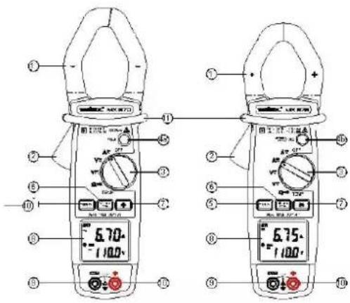
text_image
Technical diagram of two digital clamp meters with labeled parts and measurement ranges| 1 | Jaws |
| 2 | Trigger |
| 3 | Selector switch |
| 4a | HOLD Button |
| 4b | AZero & HOLD Button |
| 5 | DISPLAY Key |
| 6 | MIN MAX PEAK Key |
| 7 | BACKLIGHT Key |
| 8 | LCD display |
| 9 | COM Socket Input |
| 10 | Socket input + |
| 11 | Physical protection |
2.2 Description of LCD display
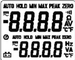
text_image
AUTO HOLD MIN MAX PEAK ZERO -8.8.8.8 Ω AV °C F AUTO HOLD MIN MAX PEAK ZERO -8.8.8.8 Hz VA °C F| MX670 | MX675 | ||
| ● | ● | Auto power-off | |
| ● | ● | MAX | Max. value |
| ● | ● | MIN | MIN value |
| ● ● | ●●● | Continuity Test | |
| ● | ● | HOLD | Freeze display |
| ● ● | Ω | Resistance measurement | |
| ● | ● | V | Voltage measurement |
| ● | ● | A | Current measurement |
| ● | ● | Hz | Frequency measurement |
| ● | ● | Battery low | |
| ● | ● | —— | Direct current |
| ● ● | ■ | Negative value | |
| ● | ● | ZERO | Adc zero function |
| ● | ● | ~ | Alternating current |
| ● | ● | PEAK | Peak Value |
| ● | ● | AUTO | Automatic ranges |
| ● | ● | °C | Degrees Celsius |
| ● | ● | °F | Degrees Fahrenheit |
3 GENERAL DESCRIPTION
3.1 Correction of zero in DC measurement
This function is present only on model MX675 to return to zero the display of the remanent magnetization of the clamp in DC measurement. When the switch is positioned on ADC and with no conductor inserted into the clamp, press the ADC ZERO & HOLD key (about 2 seconds) until display a of zero current appears. This reset to zero is also indicated by an audio beep and the display of the symbol ZERO.
This operation must usually be renewed after each high amplitude current measurement.
Elimination of zero correction is possible only by changing the function using the switch.
3.2 HOLD function - Freeze display
In model MX670, it is possible to freeze the value displayed by pressing the "HOLD" button. To deactivate this function, press the "HOLD" button a second time.
In model MX675, it is possible to freeze the value displayed by pressing the "A ZERO & HOLD" button. To deactivate this function, press the "A ZERO & HOLD" button a second time.
3.3 Automatic ranges
Depending on the function and nature of the input signals, the instrument uses automatically the best suited measurement range. The manual choice of a range is therefore not possible.
3.4 Auto power-off
The clamp will stop automatically after 10 minutes (The symbol Ⓤ is displayed).
To deactivate this function, hold down the A ZERO & HOLD button (for MX675) or the HOLD button (for MX670). Activate the clamp while turning the switch from the "OFF" position towards any position.
Release the button when the audio signal confirms the operation (the symbol 🔒 is no longer displayed).
3.5 PEAK Function (1 ms)
This function is used for measuring 1-ms peak values in voltage or current.
To activate the function, press the MIN MAX PEAK key for at least 2 seconds, until "PEAK" is displayed.
To exit this function, press the MIN MAX PEAK key for at least 2 seconds or press the A ZERO & HOLD button (MX675) twice or press the HOLD (MX670) button twice; the clamp returns to normal mode.
3.6 MAX MIN function (500 ms)
To activate the MAX MIN function, press on the MIN MAX PEAK button. The MIN value is then displayed. (the MIN symbol is displayed steady; the MAX symbol is displayed flashing)
By pressing again on the key, the MAX value will be displayed (the MIN symbol is displayed flashing; the MAX symbol is displayed and steady).
By pressing the key again, the clamp returns to normal mode.
3.7 BACKLIGHT Function
By pressing the ⚙ button, the backlight of the display goes on, press again, it goes off.
The "auto power off" function activates after 3 minutes.
3.8 DISPLAY Function
When measuring voltage or AC current, pressing the DISPLAY key replaces the nature of the secondary display by the signal frequency of the main display. Pressing again returns to the previous display.
In temperature measurement, pressing the DISPLAY key switches the displays in degrees Celsius and degrees Fahrenheit of the measured temperature.
4 OPERATION
4.1 AC voltage measurement
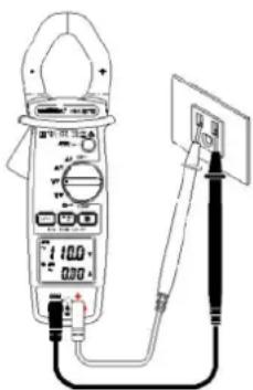
natural_image
Illustration of a digital multimeter connected to a power supply via a cable (no text or symbols visible)- Position the switch on V_ .
Connect the red test lead to the "+" terminal and the black test lead to the "COM" terminal.
Put the touch prods in contact with the measurement points under AC voltage.
Read the result of the measurement on the display.
4.2 DC voltage measurement
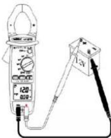
text_image
120 A-3V- Position the switch on V DC.
Connect the red test lead to the "+" terminal and the black test lead to the "COM" terminal.
Put the touch prods in contact with the measurement points under DC voltage.
Read the result of the measurement on the display. There is no secondary current display for model MX670.
4.3 Measuring AC current
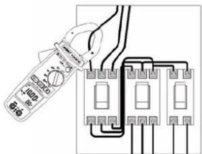
text_image
Diagram showing a multimeter connected to an electrical circuit with labeled components and wiring connections- Set the switch to A_ .
Safety reminder: The technology of this instrument allows the application or withdrawal of the clamp on bare conductors under dangerous voltage. Always ... the instrument while never going past the physical safety protection. Open the jaws by pressing the trigger. Position the clamp around the single conductor to be measured.
Release the trigger. Check that the clamp is properly closed. Read the result of the measurement on the display.
If difficult access makes reading the display impossible, press briefly on the HOLD button (MX670) or on the ACC ZERO & HOLD button (MX675) to freeze the display and read the result after withdrawal of the clamp.
Note: The measurement results are most accurate when the conductor is centred in the middle of the jaws.
4.4 DC Current measurement (MX675 only)
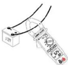
text_image
12VSet the switch to A
Once the display is stabilised, press the ABC ZERO & HOLD button to reset the display to zero.
The operating procedure is then identical to that of AC measurement. See previous paragraph.
Note: The correct display of current direction is the result of observing the positioning of the "+" indication on the clamp arm, in relation to the source.
4.5 Resistance measurement and Audio Continuity Test
Set the switch to ^-1
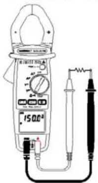
text_image
Diagram of a digital multimeter with labeled power supply and connected test probes4.5.1 Resistance measurement:
Connect the red test lead to the "+" terminal and the black test lead to the "COM" terminal.
Put the touch prods into contact with the points to be measured.
Read the result of the measurement on the display.
Note: Always check that the circuit is disconnected from the power supply before measuring resistance!
4.5.2 Audio Continuity Test :
Connect the red test lead to the "+" terminal and the black test lead to the "COM" terminal.
Put the touch prods into contact with the circuit to be tested.
If the resistance value of circuit R<35 Ω, the buzzer sounds
continuously.
Note: Always check that the circuit is disconnected from the power supply before measuring continuity!
text_image
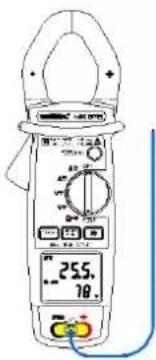
Technical line drawing of two analog multimeters with labeled probes and dials, showing measurement setup.4.6 °C/°F Temperature Measurement
text_image
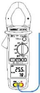
255. 78.Set the switch to TEMP.
To measure the temperature, connect the type K thermocouple probe to the input terminals, observing the polarity.
The main display is in degrees Celsius (°C) by default, and the secondary display in degrees Fahrenheit (°F). The user can change the main display to degrees Fahrenheit (°F) and the secondary display to degrees Celsius (°C) by pressing the DISPLAY key.
4.7 Measurement of voltage frequency
text_image
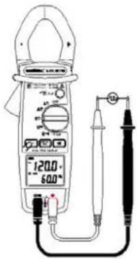
120.0 -60.0Position the switch on V AC, and press the DISPLAY key.
Connect the red test lead to the "+" terminal and the black test lead to the "COM" terminal.
Place the touch prods in contact with the points whose frequency is to be measured.
Read the frequency value on the secondary display.
The main display indicates the value of the measured TRMS voltage.
4.8 Measurement of AC current frequency
text_image
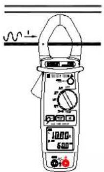
Diagram of a digital clamp meter with labeled terminals and a waveform indicator above itPosition the switch on A, and press the DISPLAY key.
Open the jaws by pressing the trigger. Position the clamp around the conductor to be measured.
Release the trigger. Check that the clamp is properly closed. Read the result of the measurement on the secondary display.
The main display indicates the value of the measured TRMS current.
5 TECHNICAL SPECIFICATIONS
5.1 General
The tolerances assigned to the values, or declared limits, constitute only the values guaranteed by the manufacturer. Values without a tolerance are for information only.
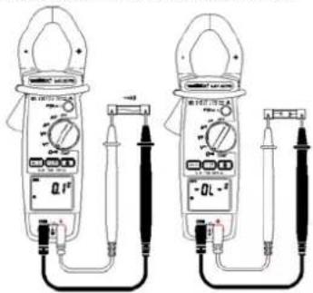
The symbol 0L is displayed when the input signals exceed the limit values possible in each measurement range.
The symbol - 0L is displayed in °C/°F measurement when there is no input signal (open circuit).
5.2 Characteristics
Accuracy is to within ± [% of the reading (L) + number of counts (cts)] in the reference conditions indicated in the appendix.
5.2.1 DC voltage
| Range | Measuring range | Resolution | Accuracy |
| 1000 V | 0.0 to 999.9 V | 0.1 V | 1% ± 2 cts |
| 1400 V | 1000 to 1400 V | 1 V | 1% ± 2 cts |
Input resistance: 1 MΩ
Overload indication: 1400 VDC
5.2.2 AC voltage
| Range | Measuring range | Resolution | Accuracy |
| 1000 V | 0.0 to 999.9 V | 0.1 V | 1.0% ± 5 cts (50 – 60Hz)1.2% ± 5 cts (60 -500Hz)2.5%± 5 cts (500Hz – 3kHz) |
Input resistance: 1 MΩ
Overload indication: 1000 Vrms
5.2.3 DC current (MX675 only)
| Range | Measuring range | Resolution | Accuracy |
| 100 A | 0.00 to 99.99 A | 0.01 A | 1.2% ± 5 cts |
| 1000 A | 100.0 to 999.9 A | 0.1 A | 2.5% ± 5 cts |
| 1400 A | 1000 to 1400 A | 1 A | 2.5% ± 5 cts |
Overload indication: 1400 ADC
5.2.4 AC current
| Range | Measuring range | Resolution | Accuracy |
| 100 A | 0.00 to 99.99 A | 0.01 A | 1.5% ± 5 cts (50 -60Hz) 2.0% ± 5 cts (60 -500Hz) 4.5% ± 5 cts (500Hz – 3kHz) |
| 1000 A | 100 to 1000 A | 0.1 A |
Overload indication: 1000 A Rms
5.2.5 Resistance (Ω)
| Range | Measuring range | Resolution | Accuracy |
| 1000 Ω | 0.0 to 999.9 Ω | 0,1 Ω | 1% ± 3cts |
| 10000 Ω | 1000 to 9999 Ω | 1 Ω | 3.3 VDC (Vmax) |
Protection: 1 000 V rms
5.2.6 Continuity
| Range | Measuring range | Accuracy |
| Continuity | Ohm FunctionBuzzer < 35 Ω | 1% ± 3 cts3.3 Vdc (Vmax) |
Protection: 1,000 Vrms
5.2.7 Frequency Hz
- For currents
| Range | Measuring range | Resolution | Accuracy Sensitivity |
| 1,000Hz | 0.0 to 999.9 Hz | 0.1 Hz | 1.0% ± 2 cts3 A Rms |
| 10,000Hz | 1000 to 9999 Hz | 1 Hz |
- For voltages
| Range | Measuring range | Resolution | Accuracy | Sensitivity |
| 1,000Hz | 0.0 to 999.9 Hz | 0.1 Hz | 1.0% ± 2 cts | 5 Vrms |
| 10,000Hz | 1000 to 9999 Hz | 1 Hz |
5.2.8 Temperature (°C/°F)
°C
| Range | Measuring range | Resolution | Accuracy |
| 1,000°C | -40 to +999.5°C | 0.5°C | 1.0% ± 2°C |
| 1,200°C | 1000 to 1,200°C | 1 °C |
°F
| Range | Measuring range | Resolution | Accuracy |
| 2192 -40 to +2192°F | 1°F | 1.0% ± 4°F | |
APPENDIX
Reference Conditions:
Measuring range: 10 to 100 % of the range.
Applied AC Signal:
- frequency between 48 and 65 Hz
- no DC component
- sinusoidal, Fc = 2
Temperature 23°C ± 3°C
No external alternative magnetic field
No electrical field
Conductor centred in jaws (in A)
5.3 Electrical safety (as per NF EN 61010):
Compliant with safety standards NF EN 61010-1 and NF EN
61010-2-032 for 600 V CAT IV or 1000V CAT III, Pollution
degree 2 and altitude < 2000 m.
5.4 General information
Digital display:
LCD dual display, 4 digits with max. indication of 9999 points.
Polarity:
When a negative signal is applied, the sign ■ appears.
Low Battery Indicator:
is displayed when the voltage supplied by the battery is lower than the operating voltage. The measurements are then guaranteed for only a short period.
Power supply:
Battery: 9 V, NEDA 1604, 6F22 alkaline
Typical autonomy: 35 hours (MX670)
30 hours (MX675)
with alkaline battery, no buzzer or backlight.
Protection index of the housing:
IP30 according to EN 60529
Maximum jaw opening:
MX670: ∅ 42 mm
MX675: ∅ 40 mm
Dimensions:
MX670: 272 x 80 x 43 mm
MX675: 257 x 80 x 43 mm
Weight:
MX670: 480 g (with battery
MX675: 440 g (with battery
5.5 Environmental conditions
5.5.1 Temperature
Operation: 0°C to 40°C, < 70% RH
Storage: -10°C to 60°C, < 80% RH
5.5.2 Altitude
Operation: < 2000 m
Storage < 12,000 m
5.5.3 Electromagnetic Compatibility (as per NF EN 61326-1)
Compliant with electromagnetic compatibility standard NF EN 61326-1
- Radiated and conducted emission (NF EN 55022)
- Radiated Immunity, criterion B (NF EN 61000-4-3)
- Conducted Immunity, criterion A (NF EN 61000-4-6)
- Electrostatic discharges, criterion A (NF EN 61000-4-2)
- Transients, criterion B (NF EN 61000-4-4)
- Shock waves, criterion A (NF EN 61000-4-5)
Note: Certain high power radioelectric frequencies are, in specific conditions, capable of interfering with the metrological integrity of the multimeter.
6 MAINTENANCE
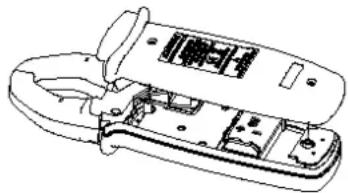
6.1 Replacing the Battery
- The symbol + appears when the battery is run down and its voltage is becoming insufficient for proper operation. It must then be replaced.
- Before changing the battery, the clamp must be disconnected from any external electrical source and must not be holding cables, set the switch to the "OFF" position.
- Unscrew the 2 screws on the lower casing.
- Replace the used battery with a new 9V battery, making sure of the correct positioning of the wires to prevent any pinching at closing.
- Refit the lower casing and close using the 2 attaching screws.
natural_image
Technical line drawing of a mechanical device with internal components (no text or symbols)6.2 Cleaning
Keep the gap between the jaws in a state of perfect cleanliness.
Set the instrument to the OFF position. Clean the unit with a cloth and a little soapy water. Wipe over with a damp cloth. Never use abrasive products or solvents. Dry carefully before any further use.
6.3 Storage
If the instrument is not used for a period exceeding 60 days, remove the battery and store it separately.
6.4 Metrological verification
Regular checks must be carried out as for all measurement or test devices.
To have your devices checked and calibrated, please contact our COFRAC approved metrology laboratories or MANUMESURE centres.
Information and address details available on request:
Tel.: 02 31 64 51 43 Fax: 02 31 64 51 09
6.5 Repairs under guarantee and outside guarantee
Send your devices to one of the Chauvin-Arnoux Metrix-approved Manumesure regional technical centres.
Information and address details available on request:
Tel.: 02 31 64 51 43 Fax: 02 31 64 51 09
Or return the instrument to your distributor for any intervention required during and after the guarantee period.
If you ship the instrument, use preferably the original packaging and specify the reasons for the return as clearly as possible in a note included with your instrument.
7 WARRANTY
This instrument is guaranteed against any defect in materials or workmanship, in accordance with the general terms and conditions of sale.
During the guarantee period (1 year), the instrument must be repaired only by the manufacturer, who reserves the right to repair the instrument or to exchange all or part of it. If the instrument is returned to the manufacturer, the transport costs are the customer's responsibility.
The guarantee is not applicable in the following cases:
- misuse of the instrument or use with incompatible equipment;
- modifications of the instrument without explicit authorisation of the manufacturer's engineering department;
- work carried out on the instrument by a person not approved by the manufacturer;
- adaptation for a specific application, not included in the definition of the instrument or the operating instructions
- impacts, falls or immersion.
TO ORDER
MX 670 Multimeter Clamp ...... MX0670
MX 675 Multimeter Clamp ...... MX0675
Delivered with:
• 1 set of leads with probe tip (red and black),
• 1 user manual 5 languages,
• 1 9V alkaline battery.
• 1 supple carrying case.
- 1 K thermocouple câble.
INHALTSVERZEICHNIS
1 ALLGEMEINE HINWEISE....38
text_image
Technical diagram of two digital multimeters with labeled parts and measurement rangesnatural_image
Line drawing of a digital multimeter connected to a power supply via a switch (no text or symbols visible)text_image
Diagram of a multimeter measuring a 12V battery with labeled terminals and scaletext_image
Diagram showing a multimeter connected to an electrical circuit with labeled components and wiring connectionstext_image
Diagram of a digital multimeter with labeled components including an ammeter, voltmeter, and probetext_image
Technical line drawing of two analog multimeters with labeled probes and dials, showing measurement ranges and connections.4.6 Temperaturmessung °C/°F
text_image
255.78text_image
Diagram of a digital multimeter with labeled scale and pointer, showing measurement reading and wiring connectionsnatural_image
Technical line drawing of a mechanical device with internal components (no text or symbols)6.2 Reinigung
text_image
Diagram of two digital multimeters with labeled parts and measurement rangestext_image
Diagram of a digital multimeter connected to a power supply via a cable, showing measurement ranges and terminal connections.text_image
Diagram of a multimeter measuring a 12V battery with labeled terminals and a close-up view showing the measurement.natural_image
Diagram showing a multimeter connected to an electrical circuit board with three switches (no text or symbols present)text_image
Diagram of a digital multimeter with labeled components including power supply, scale, and connected probestext_image
Technical line drawing of two analog multimeters with labeled probes and dials, showing measurement setup.text_image
120.0 -50.0text_image
Diagram of a digital multimeter with labeled components and a waveform indicator above itStockage: -10^ to 60^ , < 80 % RH
5.5.2 Altitudine
natural_image
Technical line drawing of a mechanical device with internal components (no text or symbols)6.2 Pulizia
text_image
Technical diagram of two digital multimeters with labeled parts and measurement rangestext_image
Diagram of a digital multimeter connected to a power supply via a cable, showing measurement ranges and terminal connections.text_image
Diagram of a multimeter measuring a 12V battery with labeled scale and probe connectionstext_image
Diagram showing a multimeter connected to an electrical circuit with labeled components and wiring connectionstext_image
Diagram of two digital multimeters with labeled probes and dials, showing measurement setup for electrical testing.text_image
Diagram of a digital clamp meter with labeled components and a waveform indicatornatural_image
Technical line drawing of a handheld electronic device with internal components (no text or symbols)6.2 Limpieza
200 Foxborough Blvd. - Foxborough - MA 02035
Tel: (508) 698-2115 - Fax: (508) 698-2118
ÖSTERREICH - Chauvin Arnoux Ges.m.b.H
Slamastrasse 29/3 - 1230 Wien
Tel: 01 61 61 961-0 - Fax: 01 61 61 961-61
SCANDINAVIA - CA Mätsystem AB
Box 4501 - SE 18304 TÄBY
Tel: +46 8 50 52 68 00 - Fax: +46 8 50 52 68 10
Waldeck House - Waldeck Road - Maidenhead SL6 8BR
Tel: 01628 788 888 - Fax: 01628 628 099
MIDDLE EAST - Chauvin Arnoux Middle East
P.O. BOX 60-154 - 1241 2020 JAL EL DIB (Beirut) - LEBANON
Tel: (01) 89 04 25 - Fax: (01) 89 04 24
CHINA - Shanghai Pu-Jiang - Enerdis Instruments Co. Ltd
3 F. 3 rd Building - N° 381 Xiang De Road - 200081 SHANGHAI
Tel: +86 21 65 21 51 96 - Fax: +86 21 65 21 61 07
http://www.chauvin-arnoux.com