
DV18DC - Drill HiKOKI - Free user manual and instructions
Find the device manual for free DV18DC HiKOKI in PDF.

| Brand | HiKOKI |
| Model | DV18DC |
| Product type | Cordless impact drill/driver |
| Rated voltage | 18 V (compatible with 36 V via MultiVolt battery) |
| No-load speed (low) | 0 - 500 min⁻¹ |
| No-load speed (high) | 0 - 2000 min⁻¹ |
| Chuck capacity | Keyless chuck, up to 13 mm |
| Drilling in wood (max.) | 38 mm |
| Drilling in metal (max.) | 13 mm |
| Drilling in concrete (hammer drilling) | 10 mm (vibration emission value 10.2 m/s²) |
| Main functions | Drilling, screwdriving, hammer drilling, reverse switch, torque adjustment (22 positions), speed selector, LED light, RFC (Reactive Force Control) function |
| Power supply | HiKOKI 18 V lithium-ion battery (BSL18xx series or BSL36A18) |
| Compatible battery type | BSL1840M, BSL1850MA, BSL36A18 (MultiVolt) |
| Weight (with heaviest battery) | Approx. 2.0 kg (depending on battery) |
| Sound pressure level | 90 dB(A) (K=5 dB(A)) |
| Sound power level | 101 dB(A) (K=5 dB(A)) |
| Vibration emissions (metal drilling) | 2.1 m/s² (K=1.5 m/s²) |
| Vibration emissions (concrete drilling) | 10.2 m/s² (K=1.5 m/s²) |
| Maintenance and cleaning | Wipe with a soft dry cloth. Do not use solvents. Clean the terminals and ventilation slots regularly. |
| Safety | Overload protection, thermal protection, anti-rebound RFC function, automatic stop in case of jamming, switch lock |
| Spare parts and repairability | Standard accessories: side handle, belt hook, screwdriver bit. Battery and charger sold separately. Repair by HiKOKI authorized service. |
| General information | Warranty according to applicable regulations. CE approval. Recycling according to WEEE directive. Manual available in multiple languages. |
Frequently Asked Questions - DV18DC HiKOKI
User questions about DV18DC HiKOKI
0 question about this device. Answer the ones you know or ask your own.
Ask a new question about this device
Download the instructions for your Drill in PDF format for free! Find your manual DV18DC - HiKOKI and take your electronic device back in hand. On this page are published all the documents necessary for the use of your device. DV18DC by HiKOKI.
USER MANUAL DV18DC HiKOKI
natural_image
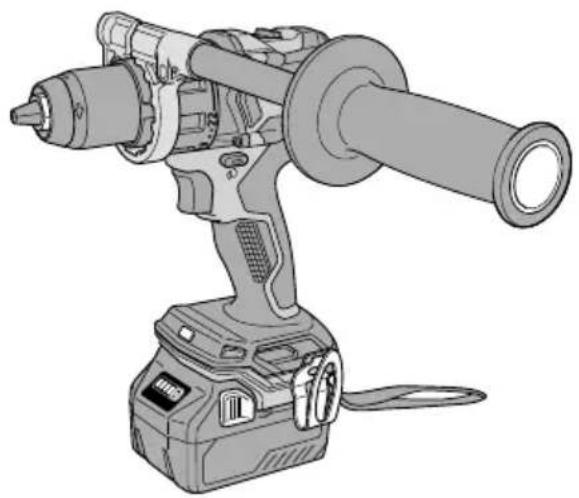
Illustration of a handheld electric drill press with a cylindrical tool and base (no text or symbols)DS18DC DS36DC
natural_image
Technical line drawing of a mechanical power tool with cylindrical shaft and base (no text or symbols)DV18DC DV36DC

en Handling instructions
de Bedienungsanleitung
fr Mode d'emploi
it Istruzioni per l'uso
nl Gebruiksaanwijzing
es Instrucciones de manejo
pt Instruções de uso
sv Bruksanvisning
da Brugsanvisning
no Bruksanvisning
fi Käyttöohjeet
el Οδηγίες χειρισμού
pl Instrukcja obsługi
hu Kezelési utasítás
cs Návod k obsluze
tr Kullanım talimatları
ro Instructiuni de utilizare
sl Navodila za rokovanje
sk Pokyny na manipuláciu
bg Инструкция за експлоатация
sr Uputstvo za rukovanje
hr Upute za rukovanje
1
natural_image
Illustration of a hand using a power tool to adjust a cylindrical component (no text or symbols present)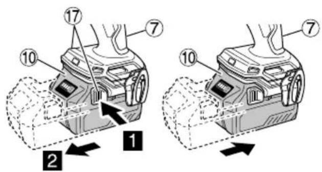
4
UC18YSL3UC18YFSL
5
natural_image
Illustration of a drill presser with motion arrows indicating tool movement (no text or symbols)

6
Min.Max.
7
DS18DC DS36DC
DV18DC DV36DC
8
DV18DC DV36DC

9


natural_image
Technical line drawing of a mechanical drill bit with a tool and directional arrow (no text or symbols)
10

11 12


13 14
16
natural_image
Diagram of a mechanical device with lever and base, showing motion paths (no text or symbols)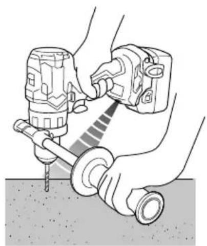
natural_image
Illustration of hands using a drill bit to adjust or install a mechanical component (no text or symbols visible)17 18
natural_image
Diagram of a mobile device connected to a wall-mounted cable, showing internal components and wiring (no text or symbols)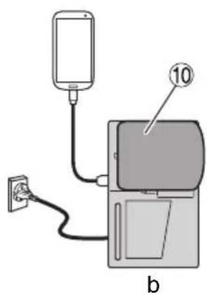
19
GENERAL POWER TOOL SAFETY WARNINGS

WARNING
Read all safety warnings, instructions, illustrations and specifications provided with this power tool.
Failure to follow all instructions listed below may result in electric shock, fi re and/or serious injury.
Save all warnings and instructions for future reference.
The term "power tool" in the warnings refers to your mains-operated (corded) power tool or battery-operated (cordless) power tool.
1) Work area safety
a) Keep work area clean and well lit. Cluttered or dark areas invite accidents
b) Do not operate power tools in explosive atmospheres, such as in the presence of fl ammable liquids, gases or dust.
Power tools create sparks which may ignite the dust or fumes.
c) Keep children and bystanders away while operating a power tool.
Distractions can cause you to lose control.
2) Electrical safety
a) Power tool plugs must match the outlet. Never modify the plug in any way. Do not use any adapter plugs with earthed (grounded) power tools.
Unmodified plugs and matching outlets will reduce risk of electric shock.
b) Avoid body contact with earthed or grounded surfaces, such as pipes, radiators, ranges and refrigerators.
There is an increased risk of electric shock if your body is earthed or grounded.
c) Do not expose power tools to rain or wet conditions. Water entering a power tool will increase the risk of electric shock.
d) Do not abuse the cord. Never use the cord for carrying, pulling or unplugging the power tool.
Keep cord away from heat, oil, sharp edges or moving parts.
Damaged or entangled cords increase the risk of electric shock.
e) When operating a power tool outdoors, use an extension cord suitable for outdoor use.
Use of a cord suitable for outdoor use reduces the risk of electric shock.
f) If operating a power tool in a damp location is unavoidable, use a residual current device (RCD) protected supply.
Use of an RCD reduces the risk of electric shock.
3) Personal safety
a) Stay alert, watch what you are doing and use common sense when operating a power tool. Do not use a power tool while you are tired or under the influence of drugs, alcohol or medication.
A moment of inattention while operating power tools may result in serious personal injury.
b) Use personal protective equipment. Always wear eye protection.
Protective equipment such as a dust mask, non-skid safety shoes, hard hat or hearing protection used for appropriate conditions will reduce personal injuries.
c) Prevent unintentional starting. Ensure the switch is in the off -position before connecting to power source and/or battery pack, picking up or carrying the tool.
Carrying power tools with your fi nger on the switch or energising power tools that have the switch on invites accidents.
d) Remove any adjusting key or wrench before turning the power tool on.
A wrench or a key left attached to a rotating part of the power tool may result in personal injury.
e) Do not overreach. Keep proper footing and balance at all times.
This enables better control of the power tool in unexpected situations.
f) Dress properly. Do not wear loose clothing or jewellery. Keep your hair and clothing away from moving parts.
Loose clothes, jewellery or long hair can be caught in moving parts.
g) If devices are provided for the connection of dust extraction and collection facilities, ensure these are connected and properly used.
Use of dust collection can reduce dust-related hazards.
h) Do not let familiarity gained from frequent use of tools allow you to become complacent and ignore tool safety principles.
A careless action can cause severe injury within a fraction of a second.
4) Power tool use and care
a) Do not force the power tool. Use the correct power tool for your application.
The correct power tool will do the job better and safer at the rate for which it was designed.
b) Do not use the power tool if the switch does not turn it on and off.
Any power tool that cannot be controlled with the switch is dangerous and must be repaired.
c) Disconnect the plug from the power source and/or remove the battery pack, if detachable, from the power tool before making any adjustments, changing accessories, or storing power tools.
Such preventive safety measures reduce the risk of starting the power tool accidentally.
d) Store idle power tools out of the reach of children and do not allow persons unfamiliar with the power tool or these instructions to operate the power tool.
Power tools are dangerous in the hands of untrained users.
e) Maintain power tools and accessories. Check for misalignment or binding of moving parts, breakage of parts and any other condition that may affect the power tool's operation. If damaged, have the power tool repaired before use.
Many accidents are caused by poorly maintained power tools.
f) Keep cutting tools sharp and clean.
Properly maintained cutting tools with sharp cutting edges are less likely to bind and are easier to control.
g) Use the power tool, accessories and tool bits etc. in accordance with these instructions, taking into account the working conditions and the work to be performed.
Use of the power tool for operations different from those intended could result in a hazardous situation.
h) Keep handles and grasping surfaces dry, clean and free from oil and grease.
English
Slippery handles and grasping surfaces do not allow for safe handling and control of the tool in unexpected situations.
5) Battery tool use and care
a) Recharge only with the charger specified by the manufacturer.
A charger that is suitable for one type of battery pack may create a risk of fire when used with another battery pack.
b) Use power tools only with specifically designated battery packs.
Use of any other battery packs may create a risk of injury and fire.
c) When battery pack is not in use, keep it away from other metal objects, like paper clips, coins, keys, nails, screws or other small metal objects, that can make a connection from one terminal to another.
Shorting the battery terminals together may cause burns or a fire.
d) Under abusive conditions, liquid may be ejected from the battery; avoid contact. If contact accidentally occurs, fl ush with water. If liquid contacts eyes, additionally seek medical help.
Liquid ejected from the battery may cause irritation or burns.
e) Do not use a battery pack or tool that is damaged or modified.
Damaged or modified batteries may exhibit unpredictable behaviour resulting in fire, explosion 2 or risk of injury.
f) Do not expose a battery pack or tool to fire or excessive temperature.
Exposure to fire or temperature above 130^ C cause explosion.
g) Follow all charging instructions and do not charge the battery pack or tool outside the temperature range specified in the instructions.
Charging improperly or at temperatures outside the specified range may damage the battery and increase the risk of fire.
6) Service
a) Have your power tool serviced by a qualified repair person using only identical replacement parts.
This will ensure that the safety of the power tool is maintained.
b) Never service damaged battery packs. Service of battery packs should only be performed by the manufacturer or authorized service providers.
PRECAUTION
Keep children and infi rm persons away.
When not in use, tools should be stored out of reach of children and infi rm persons.
CORDLESS DRIVER DRILL / COMBI DRILL SAFETY WARNINGS
Safety instructions for all operations
a) Wear ear protectors when impact drilling.
Exposure to noise can cause hearing loss.
b) Use the auxiliary handle(s).
Loss of control can cause personal injury.
c) Brace the tool properly before use.
This tool produces a high output torque and without properly bracing the tool during operation, loss of control may occur resulting in personal injury.
d) Hold the power tool by insulated gripping surfaces, when performing an operation where the cutting accessory may contact hidden wiring.
Cutting accessory contacting a "live" wire may make exposed metal parts of the power tool "live" and could give the operator an electric shock.
Safety instructions when using long drill bits
a) Never operate at higher speed than the maximum speed rating of the drill bit.
At higher speeds, the bit is likely to bend if allowed to rotate freely without contacting the workpiece, resulting in personal injury.
b) Always start drilling at low speed and with the bit tip in contact with the workpiece.
At higher speeds, the bit is likely to bend if allowed to rotate freely without contacting the workpiece, resulting in personal injury.
c) Apply pressure only in direct line with the bit and do not apply excessive pressure.
Bits can bend causing breakage or loss of control, resulting in personal injury.
ADDITIONAL SAFETY WARNINGS
-
Make sure that the area to be drilled is absolutely free of any hidden obstructions including electrical wiring, water, or gas pipes. Drilling into the aforementioned may result in electric shock or short circuit, gas leak or other hazards that can cause serious accidents or injuries.
-
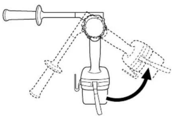
Make sure to securely hold the tool during operation. Failure to do so can result in accidents or injuries (Fig. 2).
-
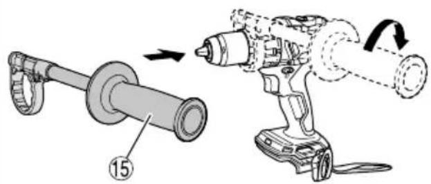
When using the tool, make sure the side handle is attached and firmly secured.
mayIf not firmly secured, the tool may jerk out of position when overburdened, resulting in injury.
-
During operation, make sure to firmly hold the tool's handle and side handle with both hands. Failure to do so may result in injury.
-
Secure the workpiece. A workpiece clamped with clamping devices or in a vice is held more secure than by hand.
-
Setting up and checking the work environment. Check if the work environment is suitable by following the precaution.
-
When mounting a bit into the keyless chuck, tighten the sleeve adequately. If the sleeve is not tight, the bit may slip or fall out, causing injury.
-
When changing the rotational speed with the shift knob, confirm that the switch is off. Changing the speed while the motor is rotating will damage the gears.
-
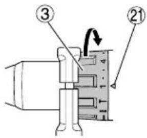
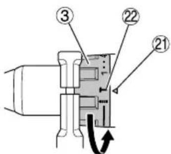
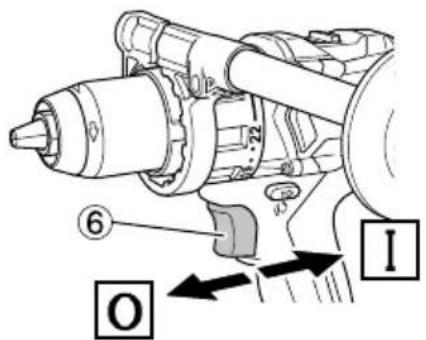
The clutch dial cannot be set between the numerals "1, 4, 7 ... 22" or the dots, and do not use with the clutch dial numeral between "22" and the line at the middle of the drill mark. Doing so may cause damage.
-
Always use this unit with clockwise rotation, when using it as impact drill. (DV18DC, DV36DC only)
-
Resting the unit after continuous work.
-
The power tool is equipped with a temperature protection circuit to protect the motor. Continuous work may cause the temperature of the unit to rise, activating the temperature protection circuit and automatically stopping operation. If this happens, allow the power tool to cool before resuming use.
-
The motor may stop in the event the tool is overloaded. In this should occur, release the tool's switch and eliminate the cause of the overload.
-
Do not touch metal parts of the tool body, bits, drills, or swarf immediately after use, as these will be hot.
-
The motor rotation may be locked to cease while the unit is used as drill. While operating the driver drill, take care not to lock the motor.
-
The use of the battery in a cold condition (below 0 degree Centigrade) can sometimes result in the weakened tightening torque and reduced amount of work. This, however, is a temporary phenomenon, and returns to normal when the battery warms up.
-
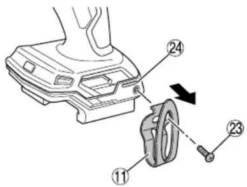
Install securely the hook. Unless the hook is securely installed, it may cause an injury while using.
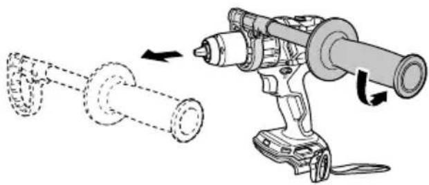
When electing to carry the tool hooked to your hip belt, make sure to detach the tool bit and side handle. Failure to do so may result in unexpected injury.
- Do not look directly into the light. Such actions could result in eye injury.
Wipe off any dirt or grime attached to the lens of the LED light with a soft cloth, being careful not to scratch the 3 lens.
Scratches on the lens of the LED light can result in decreased brightness.
-
When working at elevated locations, clear the area of other people and aware of conditions below you.
-
Always charge the battery at a temperature of 0^ C– 40^ C. A temperature of less than 0^ C will result in over charging which is dangerous. The battery cannot be charged at a temperature higher than 40^ C.
The most suitable temperature for charging is that of 20^ C– 25^ C.
- Do not use the charger continuously.
When one charging is completed, leave the charger for about 15 minutes before the next charging of battery.
-
Do not allow foreign matter to enter the hole for connecting the rechargeable battery.
-
Never disassemble the rechargeable battery and charger.
-
Never short-circuit the rechargeable battery. Shortcircuiting the battery will cause a great electric current and overheat. It results in burn or damage to the battery.
-
Do not dispose of the battery in fire. If the battery is burnt, it may explode.
-
Bring the battery to the shop from which it was purchased as soon as the post-charging battery life becomes too short for practical use. Do not dispose of the exhausted battery.
-
Do not insert object into the air ventilation slots of the charger. Inserting metal objects or inflammables into the charger air ventilation slots will result in electrical shock hazard or damaged charger.
-
When using this unit continuously, the unit may overheat, leading to damage in the motor and switch. Therefore, whenever the housing becomes hot, give the tool a break for a while.
-
Make sure that the battery is installed firmly. If it is at all loose it could come off and cause an accident.
-
Do not use the product if the tool or the battery terminals (battery mount) are deformed.
Installing the battery could cause a short circuit that could result in smoke emission or ignition.
- Keep the tool's terminals (battery mount) free of swarf and dust.
○ Prior to use, make sure that swarf and dust have not collected in the area of the terminals.
○ During use, try to avoid swarf or dust on the tool from falling on the battery.
When suspending operation or after use, do not leave the tool in an area where it may be exposed to falling swarf or dust.
Doing so could cause a short circuit that could result in smoke emission or ignition.
- Always use the tool and battery at temperatures between -5^ and 40^ .
CAUTION ON LITHIUM-ION BATTERY
To extend the lifetime, the lithium-ion battery equips with the protection function to stop the output.
In the cases of 1 to 3 described below, when using this product, even if you are pulling the switch, the motor may stop.
This is not the trouble but the result of protection function.
- When the battery power remaining runs out, the motor stops.
In such a case, charge it up immediately.
-
If the tool is overloaded, the motor may stop. In this case, release the switch of tool and eliminate causes of overloading. After that, you can use it again.
-
If the battery is overheated under overload work, the battery power may stop.
In this case, stop using the battery and let the battery cool. After that, you can use it again.
Furthermore, please heed the following warning and caution.
WARNING
In order to prevent any battery leakage, heat generation, smoke emission, explosion and ignition beforehand, please be sure to heed the following precautions.
- Make sure that swarf and dust do not collect on the battery.
During work make sure that swarf and dust do not fall on the battery.
○ Make sure that any swarf and dust falling on the power tool during work do not collect on the battery.
○ Do not store an unused battery in a location exposed to swarf and dust.
Before storing a battery, remove any swarf and dust that may adhere to it and do not store it together with metal parts (screws, nails, etc.).
-
Do not pierce battery with a sharp object such as a nail, strike with a hammer, step on, throw or subject the battery to severe physical shock.
-
Do not use an apparently damaged or deformed battery.
-
Do not use the battery for a purpose other than those specified.
-
If the battery charging fails to complete even when a specified recharging time has elapsed, immediately stop further recharging.
-
Do not put or subject the battery to high temperatures or high pressure such as into a microwave oven, dryer, or high pressure container.
-
Keep away from fi re immediately when leakage or foul odor are detected.
-
Do not use in a location where strong static electricity generates.
-
If there is battery leakage, foul odor, heat generated, discolored or deformed, or in any way appears abnormal during use, recharging or storage, immediately remove it from the equipment or battery charger, and stop use.
-
Do not immerse the battery or allow any fluids to flow inside. Conductive liquid ingress, such as water, can cause damage resulting in fire or explosion. Store your battery in a cool, dry place, away from combustible and fl ammable items. Corrosive gas atmospheres must be avoided.
CAUTION
- If liquid leaking from the battery gets into your eyes, do not rub your eyes and wash them well with fresh clean water such as tap water and contact a doctor immediately.
If left untreated, the liquid may cause eye-problems.
- If liquid leaks onto your skin or clothes, wash well with clean water such as tap water immediately.
There is a possibility that this can cause skin irritation.
- If you find rust, foul odor, overheating, discolor, deformation, and/or other irregularities when using the battery for the first time, do not use and return it to your supplier or vendor.
English
WARNING
If a conductive foreign matter enters in the terminal of lithium ion battery, the battery may be shorted, causing fire. When storing the lithium ion battery, obey surely the rules of following contents.
○ Do not place conductive debris, nail and wires such as iron wire and copper wire in the storage case.
To prevent shorting from occurring, load the battery in the tool or insert securely the battery cover for storing until the ventilator is not seen.
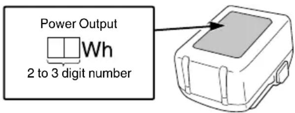
REGARDING LITHIUM-ION BATTERY TRANSPORTATION
When transporting a lithium-ion battery, please observe the following precautions.
WARNING
Notify the transporting company that a package contains a lithium-ion battery, inform the company of its power output and follow the instructions of the transportation company when arranging transport.
☐ Lithium-ion batteries that exceed a power output of 100 Wh are considered to be in the freight classification of Dangerous Goods and will require special application procedures.
☐ For transportation abroad, you must comply with international law and the rules and regulations of the destination country.
USB DEVICE CONNECTION PRECAUTIONS (UC18YSL3)
When an unexpected problem occurs, the data in a USB device connected to this product may be corrupted or lost. Always make sure to back up any data contained in the USB device prior to use with this product.
Please be aware that our company accepts absolutely no responsibility for any data stored in a USB device that is corrupted or lost, nor for any damage that may occur to a connected device.
WARNING
- Prior to use, check the connecting USB cable for any defect or damage.
Using a defective or damaged USB cable can cause smoke emission or ignition.
○ When the product is not being used, cover the USB port with the rubber cover.
Buildup of dust etc. in the USB port can cause smoke emission or ignition.
NOTE
- There may be an occasional pause during USB recharging.
○ When a USB device is not being charged, remove the USB device from the charger.
Failure to do so may not only reduce the battery life of a USB device, but may also result in unexpected accidents.
- It may not be possible to charge some USB devices, depending on the type of device.
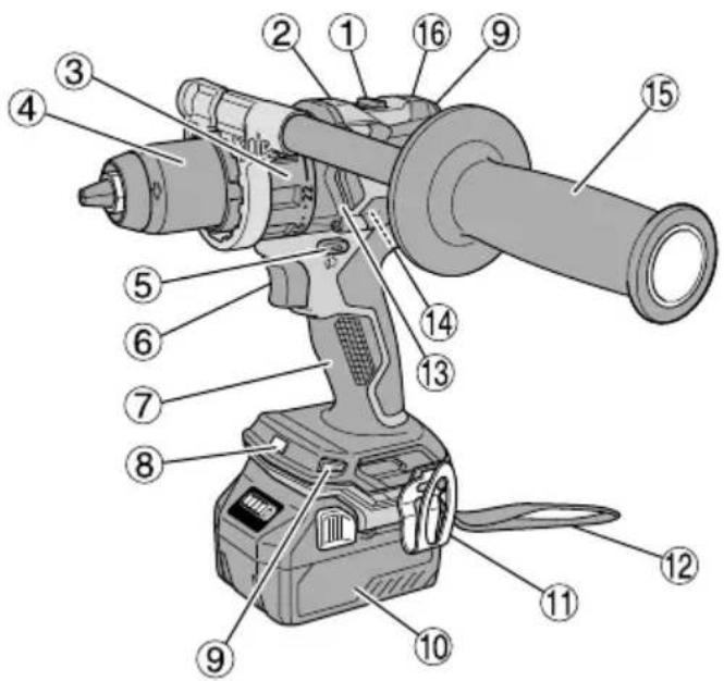
NAMES OF PARTS (Fig. 1–Fig. 19)
| 1 | Shift knob | 15 | Side handle |
| 2 | Name plate Housing | 16 | |
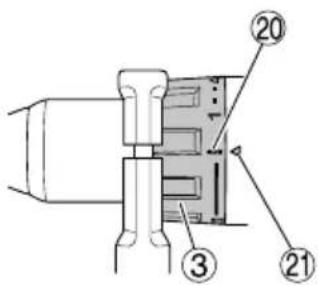
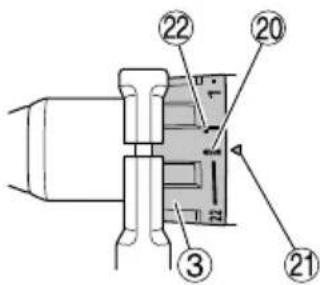
| 3 | Clutch dial Latch | 17 | |
| 4 | Keyless chuck Charge indicator lamp | ||
| 5 | Push button Pilot lamp | 19 | |
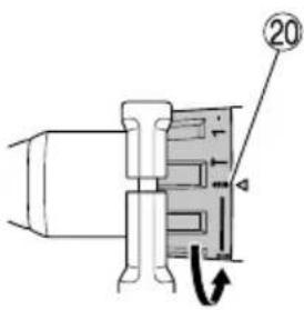
| 6 | Trigger switch | 20 | Drill mark |
| 7 | Handle Triangle mark | 21 | |
| 8 | LED light Hammer mark | 22 | |
| 9 | Ventilation holes Screw | 23 | |
| 10 | Battery Groove | 24 | |
| 11 | Hook | 25 | Sleeve |
| 12 | Strap | 26 | Remaining battery indicator switch |
| 13 | Gear case | 27 | Remaining battery indicator lamp |
| 14 | Motor | 28 | Display panel |
SYMBOLS
WARNING
The following show symbols used for the machine. Be sure that you understand their meaning before use.
* Depending on attached battery. The heaviest weight is measured with BSL36B18 (sold separately).
| DS18DC, DS36DC: Cordless Driver DrillDV18DC, DV36DC: Cordless Combi Drill | |
 | To reduce the risk of injury, user must read instruction manual. |
 | Only for EU countriesDo not dispose of electric tools together with household waste material!In observance of European Directive 2012/19/EU on waste electrical and electronic equipment and its implementation in accordance with national law, electric tools that have reached the end of their life must be collected separately and returned to an environmentally compatible recycling facility. |
| Direct current | |
| V | Rated voltage |
| n_0 | No-load speed |
| Bpm | Impact rate |
| Ls | Low speed |
| Hs | High speed |
 | Brick |
 | Wood |
 | Metal |
 | Machine screw |
| Wood screw | |
 | Drill chuck capacity |
 | Weight*(According to EPTA-Procedure 01/2014) |
 | Drilling |
 | Impact drilling |
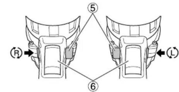
 | Switching ON |
 | Switching OFF |
 | Disconnect the battery |
 | Change rotation speed – High speed |
 | Change rotation speed – Low speed |
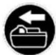
 | Clockwise rotation |
 | Counterclockwise rotation |
 | Warning |
Battery
 | Lights;The battery remaining power is over 75%. |
 | Lights;The battery remaining power is 50%-75%. |
 | Lights;The battery remaining power is 25%-50%. |
 | Lights;The battery remaining power is less than 25%. |
 | Blinks;The battery remaining power is nearly empty.Recharge the battery soonest possible. |
 | Blinks;Output suspended due to high temperature.Remove the battery from the tool and allow it to fully cool down. |
 | Blinks;Output suspended due to failure or malfunction.The problem may be the battery so please contact your dealer. |
STANDARD ACCESSORIES
In addition to the main unit (1 unit), the package contains the accessories listed on page 229.
Standard accessories are subject to change without notice.
APPLICATIONS
○ Driving and removing of machine screws, wood screws, tapping screws, etc.
○ Drilling of various metals
○ Drilling of various woods
○ Drilling of brick and concrete block, etc.
○ Driving and removing of machine screws, wood screws, tapping screws, etc.
○ Drilling of various metals
○ Drilling of various woods
SPECIFICATIONS
1. Power tool
The specifications of this machine are listed in the Table on page 228.
* Existing batteries (BSL3660/3620/3626, BSL18xx and BSL14xx series) cannot be used with this tool. Use a multi volt type battery.
NOTE
Due to HiKOKI's continuing program of research and development, the specifications herein are subject to change without prior notice.
- Battery
| Model BSL1840M BSL1850MA BSL36A18 | |||
| Voltage 18 V 18 V 36 V /18 V* | |||
| Battery capacity | 4.0 Ah 5.0 | Ah 2.5 Ah / 5.0 | Ah* |
* The tool itself will automatically switch over.
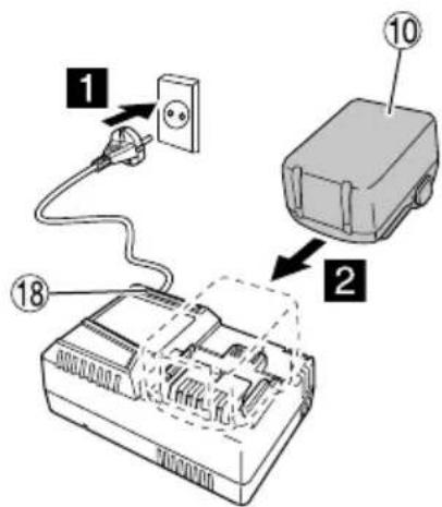
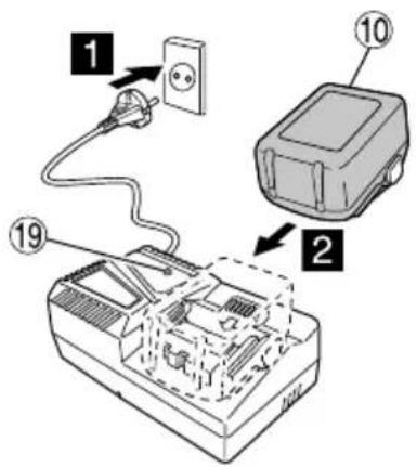
CHARGING
Before using the power tool, charge the battery as follows.
- Connect the charger's power cord to the receptacle.
When connecting the plug of the charger to a receptacle, the pilot lamp will blink in red (At 1-second intervals).
- Insert the battery into the charger.
Firmly insert the battery into the charger as shown in Fig. 4 (on page 2).
- Charging
When inserting a battery in the charger, charging will commence and the pilot lamp will light continuously in red.
When the battery becomes fully recharged, the pilot lamp will blink in red. (At 1-second intervals) (See Table 1)
● Pilot lamp indication
The indications of the pilot lamp will be as shown in Table 1, according to the condition of the charger or the rechargeable battery.
Table 1
| Indications of the pilot lamp (RED) | ||
| Before charging | ON/OFF at 0.5 sec. intervals | Plugged into power source |
| While charging | Lights continuously | — |
| Charging complete | ON/OFF at 0.5 sec. intervals | — |
| Overheat standby | Lights for 1 sec. at intervals of 0.5 sec. | Battery overheated. Unable to charge. (Charging will commence when battery cools) |
| Charging impossible | ON/OFF at 0.1 sec. intervals | Malfunction in the battery or the charger |
● Regarding the temperatures and charging time of the battery.
The temperatures and charging time will become as shown in Table 2.
Table 2
| Battery\Charger | UC18YFSL | |
| Charging voltage V 14.4-18 | ||
| Weight kg 0.5 | ||
| Temperatures at which the battery can be recharged | 0°C-50°C | |
| Charging time for battery capacity, approx. (At 20°C) | ||
| 1.5 Ah | min | 22 |
| 2.0 Ah | min | 30 |
| 2.5 Ah | min | 35 |
| 3.0 Ah | min | 45 |
| 4.0 Ah | min | 60 |
| 5.0 Ah | min | 75 |
| 6.0 Ah | min | 90 |
| 8.0 Ah | min | 120 |
| Number of battery cells 4-10 | ||
NOTE
The recharging time may vary according to the ambient temperature and power source voltage.
CAUTION
When the battery charger has been continuously used, the battery charger will be heated, thus constituting the cause of the failures. Once the charging has been completed, give 15 minutes rest until the next charging.
-
Disconnect the charger's power cord from the receptacle.
-
Hold the charger firmly and pull out the battery. NOTE
Be sure to pull out the battery from the charger after use, and then keep it.
Regarding electric discharge in case of new batteries, etc.
As the internal chemical substance of new batteries and batteries that have not been used for an extended period is not activated, the electric discharge might be low when using them the first and second time. This is a temporary phenomenon, and normal time required for recharging will be restored by recharging the batteries 2–3 times.
How to make the batteries perform longer.
(1) Recharge the batteries before they become completely exhausted.
When you feel that the power of the tool becomes weaker, stop using the tool and recharge its battery. If you continue to use the tool and exhaust the electric current, the battery may be damaged and its life will become shorter.
(2) Avoid recharging at high temperatures.
A rechargeable battery will be hot immediately after use. If such a battery is recharged immediately after use, its internal chemical substance will deteriorate, and the battery life will be shortened. Leave the battery and recharge it after it has cooled for a while.
CAUTION
☐ If the battery is charged while it is heated because it has been left for a long time in a location subject to direct sunlight or because the battery has just been used, the pilot lamp of the charger lights up green or lights for 1 second, does not light for 0.5 seconds (off for 0.5 seconds). In such a case, first let the battery cool, then start charging.
When the pilot lamp flickers in red (at 0.2-seconds intervals), check for and take out any foreign objects in the charger's battery connector. If there are no foreign objects, it is probable that the battery or charger is malfunctioning. Take it to your authorized Service Center.
- Connect the charger's power cord to the receptacle.
When connecting the plug of the charger to a receptacle, the charge indicator lamp will blink in red (At 1-second intervals).
- Insert the battery into the charger.
Firmly insert the battery into the charger as shown in Fig. 4 (on page 2).
- Charging
When inserting a battery in the charger, the charge indicator lamp will blink in blue.
When the battery becomes fully recharged, the charge indicator lamp will light up in green. (See Table 3)
(1) Charge indicator lamp indication
The indications of the charge indicator lamp will be as shown in Table 3, according to the condition of the charger or the rechargeable battery.
Table 3
| Charger status | Status of indicator lamp | Indication meaning |
| Before charging | ON/OFF at 0.5 sec. intervals (RED) | Plugged into power source *1 |
| While charging | Lights for 0.5 sec. at intervals of 1 sec. (BLUE) | Charged at less than 50% |
| Lights for 1 sec. at intervals of 0.5 sec. (BLUE) | Charged at less than 80% | |
| Lights continuously (BLUE) | Charged at more than 80% | |
| Charging complete | Lights continuously (GREEN)(Continuous buzzer sound: about 6 sec.) | |
| Overheat standby | ON/OFF at 0.3 sec. intervals (RED) | Battery overheated. Unable to charge. *2 |
| Charging impossible | ON/OFF at 0.1 sec. intervals (PURPLE)(Intermittent buzzer sound; about 2 sec.) | Malfunction in the battery or the charger *3 |
*1 If the red lamp continues to blink even after the charger has been attached, check to confirm that the battery has been fully inserted.
*2 Although charging will start once the battery has cooled down even when left in situ, the best practice is to remove the battery and allow it to cool down in a shaded, well-ventilated location before charging.
*3
- Fully insert the battery.
☐ Check to confirm that no foreign matter is stuck to the battery mount or terminals.
○ Charging will take longer at extremely low ambient temperatures. Charge the battery in a warm location (such as indoors).
- Do not block the air vent. Otherwise the interior will overheat, reducing the charger's performance.
○ If the cooling fan is not operating, contact a HiKOKI Authorized Service Center for repairs.
(2) Regarding the temperatures and charging time of the rechargeable battery
The temperatures and charging time will become as shown in Table 4.
Table 4
| Model | UC18YSL3 | ||
| Type of battery Li-ion | |||
| Charging voltage 14.4–18 V | |||
| Temperatures at which the battery can be recharged | 0°C–50°C | ||
| Charging time for battery capacity, approx.(At 20°C) | 1.5 Ah 15 min | ||
| 2.0 Ah 20 min | |||
| 2.5 Ah 25 min | |||
| 3.0 Ah | 20 min(BSL1430C, BSL1830C: 30 min) | ||
| 4.0 Ah | 26 min(BSL1840M: 40 min) | ||
| 5.0 Ah 32 min | |||
| 6.0 Ah 38 min | |||
| 8.0 Ah 52 min | |||
| Multi volt battery | 1.5 Ah (×2 unit) | ||
| 2.5 Ah (×2 unit) | |||
| 4.0 Ah (×2 unit) | |||
| Number of battery cells 4–10 | |||
| Charging voltage for USB 5 V | |||
| Charging current for USB 2 A | |||
| Weight 0.6 kg | |||
NOTE
The recharging time may vary according to the ambient temperature and power source voltage.
4. Disconnect the charger's power cord from the receptacle.
5. Hold the charger firmly and pull out the battery.
NOTE
Be sure to pull out the battery from the charger after use, and then keep it.
Regarding electric discharge in case of new batteries, etc.
As the internal chemical substance of new batteries and batteries that have not been used for an extended period is not activated, the electric discharge might be low when using them the first and second time. This is a temporary phenomenon, and normal time required for recharging will be restored by recharging the batteries 2–3 times.
How to make the batteries perform longer.
When you feel that the power of the tool becomes weaker, stop using the tool and recharge its battery. If you continue to use the tool and exhaust the electric current, the battery may be damaged and its life will become shorter.
(1) Recharge the batteries before they become completely exhausted.
(2) Avoid recharging at high temperatures.
A rechargeable battery will be hot immediately after use. If such a battery is recharged immediately after use, its internal chemical substance will deteriorate, and the battery life will be shortened. Leave the battery and recharge it after it has cooled for a while.
English
CAUTION
☐ If the battery is charged while it is heated because it has been left for a long time in a location subject to direct sunlight or because the battery has just been used, the charge indicator lamp of the charger lights for 0.3 seconds, does not light for 0.3 seconds (off for 0.3 seconds). In such a case, first let the battery cool, then start charging.
When the charge indicator lamp flickers (at 0.2-second intervals), check for and take out any foreign objects in the charger's battery connector. If there are no foreign objects, it is probable that the battery or charger is malfunctioning. Take it to your authorized Service Center.
MOUNTING AND OPERATION
| Action Figure Page | ||
| Removing and inserting the battery | 3 | 2 |
| Charging 4 2 | ||
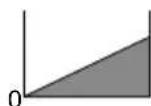
| Installing / Removing the side handle | 5 | 3 |
| Tightening torque adjustment 6 3 | ||
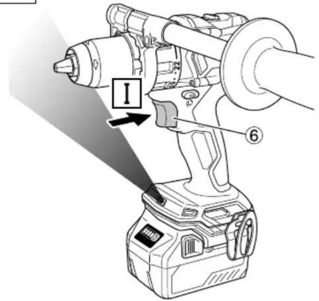
| Selecting the drill position 7 3 | ||
| Selecting the impact position 8 3 | ||
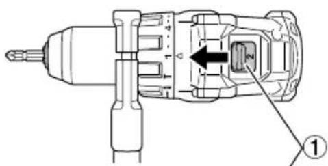
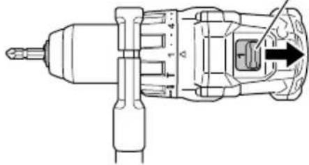
| Change rotation speed 9 3 | ||
| Mounting and removing the hook 10 4 | ||
| How to use the LED light | 11 4 | |
| Mounting the bit | 12 4 | |
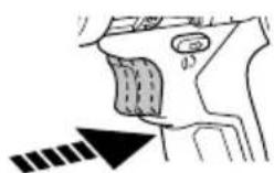
| Reversing the rotational direction | 13 4 | |
| Switch operation | 14 4 | |
| Remaining battery indicator | 15 5 | |
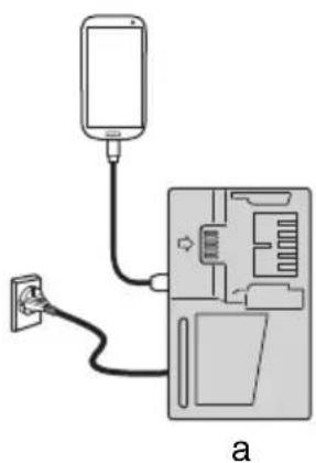
| Charging a USB device from a electrical outlet | 17-a | 5 |
| Charging a USB device and battery from a electrical outlet | 17-b | 5 |
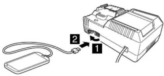
| How to recharge USB device | 18 5 | |
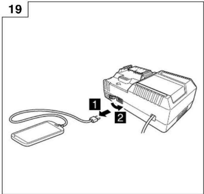
| When charging of USB device is completed | 19 | 6 |
| Selecting accessories | — | 230 |
RFC (Reactive force control)
This product features RFC.
This stops the motor automatically if the tool is jerking excessively.
The LED light flashes to indicate that RFC has been activated.
If this occurs, release your finger from the switch before restarting. (Fig.16)
NOTE
● RFC may not always activate under certain working conditions or situations.
● Take care to hold the tool firmly to prevent any jerking motion.
- RFC may also activate if you change position suddenly while holding the tool.
LED LIGHT WARNING SIGNALS
This product features functions that are designed to protect the tool itself as well as the battery. If any of the safeguard functions are triggered during operation, the LED light will blink as described in Table 5. When any of the safeguard functions are triggered, immediately remove your finger from the switch and follow the instructions described under corrective action.
Table 5
| Safeguard Function | LED Light Display | Corrective Action |
| Overburden Protection | On 0.1 second/off0.1 second(rapid blinking)Blinks for approximately 3 seconds after the switch has been released. | If the operating with the shift knob set on “2”, adjust to “1” and continue operation.Remove the cause of the overburdening. |
| RFC | On 0.15 second/off0.15 second × 3 times/Off2 secondsBlinks for approximately 3 seconds after the switch has been released. | Remove the problem causing the tool to jerk excessively.When operating the tool, firmly hold the tool to make sure it doesn't jerk. |
| Temperature Protection | On 0.5 second/Off 0.5 second(slow blinking)Blinks while protection is in effect. | Allow the tool and battery to thoroughly cool. |
MAINTENANCE AND INSPECTION
WARNING
Be sure to turned off the switch and remove the battery before maintenance and inspection.
1. Inspecting the tool
Since use of as dull tool will degrade efficiency and cause possible motor malfunction, sharpen or replace the tool as soon as abrasion is noted.
2. Inspecting the mounting screws
Regularly inspect all mounting screws and ensure that they are properly tightened. Should any of the screws be loose, retighten them immediately. Failure to do so could result in serious hazard.
3. Maintenance of the motor
The motor unit winding is the very “heart” of the power tool. Exercise due care to ensure the winding does not become damaged and/or wet with oil or water.
4. Inspection of terminals (tool and battery)
Check to make sure that swarf and dust have not collected on the terminals.
On occasion check prior, during and after operation.
CAUTION
Remove any swarf or dust which may have collected on the terminals.
Failure to do so may result in malfunction.
5. Cleaning on the outside
When the power tool is stained, wipe with a soft dry cloth or a cloth moistened with soapy water. Do not use chloric solvents, gasoline or paint thinner, for they melt plastics.
6. Storage
Store the power tool and battery in a place in which the temperature is less than 40^ C and out of reach of children.
NOTE
Storing lithium-ion batteries.
Make sure the lithium-ion batteries have been fully charged before storing them.
Prolonged storage (3 months or more) of batteries with a low charge may result in performance deterioration, signifi cantly reducing battery usage time or rendering the batteries incapable of holding a charge. However, signifi cantly reduced battery usage time m be recovered by repeatedly charging and using the batteries two to fi ve times.
If the battery usage time is extremely short despite repeated charging and use, consider the batteries dead and purchase new batteries.
CAUTION
In the operation and maintenance of power tools, the safety regulations and standards prescribed in each country must be observed.
Important notice on the batteries for the HiKOKI cordless power tools
Please always use one of our designated genuine batteries. We cannot guarantee the safety and performance of our cordless power tool when used with batteries other than these designated by us, or when the battery is disassembled and modified (such as disassembly and replacement of cells or other internal parts).
GUARANTEE
We guarantee HiKOKI Power Tools in accordance with statutory/country specific regulation. This guarantee does not cover defects or damage due to misuse, abuse, or normal wear and tear. In case of complaint, please send the Power Tool, undismantled, with the GUARANTEE CERTIFICATE found at the end of this Handling instruction, to a HiKOKI Authorized Service Center.
Information concerning airborne noise and vibration
The measured values were determined according to EN62841 and declared in accordance with ISO 4871.
Measured A-weighted sound power level:
86 dB (A) (DS18DC)
91 dB (A) (DS36DC)
101 dB (A) (DV18DC)
100 dB (A) (DV36DC)
Measured A-weighted sound pressure level:
75 dB (A) (DS18DC)
80 dB (A) (DS36DC)
90 dB (A) (DV18DC)
89 dB (A) (DV36DC)
Uncertainty K: 5 dB (A).
Wear hearing protection.
Vibration total values (triax vector sum) determined according to EN62841.
Drilling into metal:
Vibration emission value a_h , D = 2.8m / s^2 (DS18DC)
2.8 2(DS36DC)
2.1 2(DV18DC)
2.7 2(DV36DC)
Uncertainty K = 1.5 m/s2
Impact drilling into concrete:
Vibration emission value a_h ,ID = 10.2m / s (DV18DC)
9.2 m/s2 (DV36DC)
Uncertainty K = 1.5 m/s² (DV18DC, DV36DC)
The declared vibration total value and the declared noise emission value have been measured in accordance with a standard test method and may be used for comparing one tool with another.
They may also be used in a preliminary assessment of exposure.
WARNING
☐ The vibration and noise emission during actual use of the power tool can differ from the declared total value depending on the ways in which the tool is used especially what kind of workpiece is processed; and
- Identify safety measures to protect the operator that are based on an estimation of exposure in the actual conditions of use (taking account of all parts of the operating cycle such as the times when the tool is switched off and when it is running idle in addition to the trigger time).
NOTE
Due to HiKOKI's continuing program of research and development, the specifications herein are subject to change without prior notice.
ALLGEMEINE
WAARSCHUWINGSSIGNALEN LED-LAMPJE
SIKKERHETSFORHOLDSREGLER FOR ELEKTROVERKT∅Y
ADVARSEL
VEDLIKEHOLD OG INSPEKSJON
ADVARSEL
| Model | BSL1840M | BSL1850MA | BSL36A18 |
| Tensiune | 18 V 18 V | 36 V / 18 V* | |
| Capacitate accumulator | 4,0 Ah | 5,0 Ah | 2,5 Ah / 5,0 Ah* |
RFC (Control al forței reactive)
natural_image
Line drawing of a battery pack with control panel and display (no text or symbols)BSL36..18
natural_image
Line drawing of a portable electronic device with a display and control panel (no text or symbols)
natural_image
Line drawing of a battery pack with a digital display and internal circuit (no text or symbols)BSL18..
natural_image
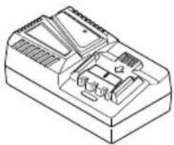
Line drawing of a mechanical component with internal slots and housing (no text or symbols)UC18YSL3 (14,4V-18V)
natural_image
Isometric line drawing of a mechanical or electronic component with internal components (no text or symbols)UC18YFSL (14,4V-18V)
natural_image
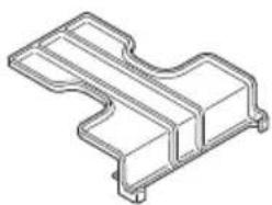
Technical line drawing of a mechanical bracket component (no text or symbols)329897

natural_image
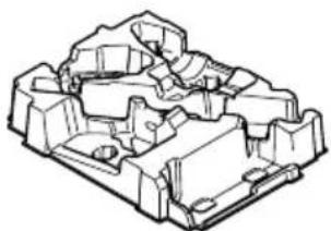
Isometric technical drawing of a mechanical housing or enclosure with internal components (no text or symbols)336471
natural_image
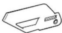
Technical line drawing of a mechanical housing or enclosure component (no text or symbols)379127
Light Gold: 377857
Titanium Silver: 377858
Sky Blue: 377859
Violet: 377860
Signal Red: 377861
| English Dansk Română | ||||
| GUARANTEE CERTIFICATE1 Model No.2 Serial No.3 Date of Purchase4 Customer Name and Address5 Dealer Name and Address(Please stamp dealer name and address) | GARANTIBEVIS1 Modelnummer2 Serienummer3 Købsdato4 Kundes navn og adresse5 Forhandlers navn og adresse(Indsæt stempel med forhandlers navn og adresse) | CERTIFICAT DE GARANTIE1 Model nr.2 Nr. de serie3 Data cumpäräri4 Numele și adresa clientului5 Numele și adresa distribuitorului(Vå rugăm aplicați štampila cu numele și adresa distribuitorului) | ||
| Deutsch Norsk Slovenščina | ||||
| GARANTIESCHEIN1 Modell-Nr.2 Serien-Nr.3 Kaufdatum4 Name und Anschrift des Kunden5 Name und Anschrift des Händlers(Bitte mit Namen und Anschrift des Handlers abstempeln) | GARANTISERTIFIKAT1 Modellnr.2 Serienr.3 Kjøpsdato4 Kundens navn og adresse5 Forhandlerens navn og adresse(Vennligst stempel forhandlerens navn og adresse) | GARANCIJSKO POTRDILO1 Št. modela2 Serijska št.3 Datum nakupa4 Ime in naslov kupca5 Ime in naslov prodajalca(Prosimo vtsnite žig z imenom in naslovom prodajalca) | ||
| Français Suomi Slovenčina | ||||
| CERTIFICAT DE GARANTIE1 No. de modèle2 No de série3 Date d'achat4 Nom et adresse du client5 Nom et adresse du revendeur(Cachet portant le nom et l'adresse du revendeur) | TAKUUTODISTUS1 Malli nro2 Sarja nro3 Ostopáivámäärä4 Asiakkaan nimi ja osoite5 Myyjän nimi ja osoite(Leimaa myyjän nimi ja osoite) | ZÁRUČNÝ LISTA1 Č. modelu2 Sériové č.3 Dátum zakúpenia4 Meno a adresa zákazníka5 Názov a adresa predajcu(Pečiatka s názvom a adresou predajcu) | ||
| Italiano Ελληνικά Βългарски | ||||
| CERTIFICATO DI GARANZIA1 Modello2 N° di serie3 Data di acquisto4 Nome e indirizzo dell'acquirente5 Nome e indirizzo del rivenditore(Si prega di apporre il timbro con questi dati) | ПІЗТОПОІНТІКО ЕГГУНЄНЕ1 Ар. Монтёлou2 Аู่ємів Ар.3 Нμερομηνία αγοράς4 ́Овоја кай дисібунуєн пелáтн5 ́Овоја кай дисібунуєн іметапшлітн’(Паракалоўєе va χρησιμοποιηθεί σφραγίδα) | ГАРАНЦИОНЕН СЕРТИФИКАТ1 Модел No2 Сериен No3 Дата за закупуване4 Име и адрес на клиента5 Име и адрес на търговеца(Моля, отпечатайте името и адрес на дильра) | ||
| Nederlands Polski Srpski | ||||
| GARANTIEBEWIJS1 Modelnummer2 Seriennummer3 Datum van aankoop4 Naam en adres van de gebruiker5 Naam en adres van de handelaar(Stempel a.u.b. naam en adres vande de handelaar) | GWARANCJA1 Model2 Numer seryjny3 Data zakupu4 Nazwa klienta i adres5 Nazwa dealera i adres(Pieczęć punktu sprzedaży) | GARANTNI SERTIFIKAT1 Br. modela.2 Serijski br.3 Datum kupovine4 Ime i adresa kupca5 Ime i adresa prodavca(Molimo da stavite pečat na ime i adresu trgovca) | ||
| Español Magyar Hrvatski | ||||
| CERTIFICADO DE GARANTÍA1 Número de modelo2 Número de serie3 Fecha de adquisición4 Nombre y dirección del cliente5 Nombre y dirección del distribuidor(Se ruega poner el sello del distribuidor con su nombre y dirección) | GARANCIA BIZONYLAT1 Tipusszám2 Sorozatszám3 A vásárlás dátuma4 A Vásárló neve és címe5 A Kereskedő neve és címe(Kárjük ide olhelyezni a Kereskedő nevének és címěnek pecsétjét) | JAMSTVENI CERTIFIKAT1 Br modela.2 Serijski br.3 Datum kupnje4 Ime i adresa kupca5 Ime i adresa trgovca(Molimo stavite pečat na ime i adresu trgovca) | ||
| Português Čeština | ||||
| CERTIFICADO DE GARANTIA1 Número do modelo2 Número do série3 Data de compra4 Nome e morada do cliente5 Nome e morada do distribuidor(Por favor, carimbe o nome e morada do distribuidor) | ZÁRUČNÍ LIST1 Model č.2 Série č.3 Datum nákupu4 Jméno a adresa zákazníka5 Jméno a adresa prodejce(Prosíme o razitko se jménem a adresou prodejce) | |||
| Svenska Türkçe | ||||
| GARANTICERTIFIKAT1 Modellnr2 Serienr3 Inköpsdatum4 Kundens namn och adress5 Försäljarens namn och adress(Stámpla försäljarens namn och adress) | GARANTI SERTÍFÍKASI1 Model No.2 Seri No.3 Satin Alma Tarihi4 Müşteri Adı ve Adresi5 Bayi Adı ve Adresi(Lüften bayi adini ve adresini kaşe olarak basin) | |||
HiKOKI
| 1 | |
| 2 | |
| 3 | |
| 4 | |
| 5 |

natural_image
Line drawing of a quill pen with inkwell, no text or symbols present
natural_image
Line drawing of a quill pen with inkwell, no text or symbols present
natural_image
Line drawing of a quill pen with inkwell, no text or symbols presentSiemensring 34, 47877 willich, Germany
Tel: +49 2154 49930
Fax: +49 2154 499350
URL: http://www.hikoki-powertools.de
Hikoki Power Tools Netherlands B.V.
Brabanthaven 11, 3433 PJ Nieuwegein, The Netherlands
Tel: +31 30 6084040
Fax: +31 30 6067266
URL: http://www.hikoki-powertools.nl
Hikoki Power Tools (U.K.) Ltd.
25 Majestic Road, Southampton, SO16 OYT,
United Kingdom
Tel: +44 1908 660663
Fax: +44 1908 606642
URL: http://www.hikoki-powertools.uk
Hikoki Power Tools France S.A.S.
Hikoki Power Tools Belgium N.V./S.A.
Koningin Astridlaan 51, B-1780 Wemmel, Belgium
Tel: +32 2 460 1720
Fax: +32 2 460 2542
URL http://www.hikoki-powertools.be
Hikoki Power Tools Italia S.p.A
Via Piave 35, 36077, Altavilla Vicentina (VI), Italy
Tel: +39 0444 548111
Fax: +39 0444 548110
URL: http://www.hikoki-powertools.it
Hikoki Power Tools Ibérica, S.A.
C/ Puigbarral, 26-28, Pol. Ind. Can Petit, 08227 Terrassa
(Barcelona), Spain
Tel: +34 93 735 6722
Fax: +34 93 735 7442
URL: http://www.hikoki-powertools.es
Kjeller Vest 7, N-2007 Kjeller, Norway
Tel: (+47) 6692 6600
Fax: (+47) 6692 6650
URL: http://www.hikoki-powertools.no
Hikoki Power Tools Sweden AB
Rotebergsvagen 2B SE-192 78 Sollentuna, Sweden
Tel: (+46) 8 598 999 00
Fax: (+46) 8 598 999 40
URL: http://www.hikoki-powertools.se
Hikoki Power Tools Denmark A/S
Lillebaeltsvej 90, 6715 Esbjerg N, Denmark
Tel: (+45) 75 14 32 00
Fax: (+45) 75 14 36 66
URL: http://www.hikoki-powertools.dk
Hikoki Power Tools Finland Oy
Tupalankatu 9, 15680 Lahti, Finland
Tel: (+358) 20 7431 530
Fax: (+358) 20 7431 531
URL: http://www.hikoki-powertools.fi
Hikoki Power Tools Hungary Kft.
Hikoki Power Tools Romania S.R.L.
Ring Road, No. 66, Mustang Traco Warehouses, Warehouse
No.1, Pantelimon City, 077145, Ilfov County, Romania
| DECLARATION OF CONFORMITYWe declare under our sole responsibility that Cordless Driver Drill/Cordless Combi Drill, identified by type and specific identification code *1), is in conformity with all relevant requirements of the UK regulations *2) and Designated standards *3). Technical file at *4) – See below.This declaration is applicable to the product affixed UKCA marking. | |
| *1) DS18DC C362682SDS36DC C362688SDV18DC C362693SDV36DC C362699S*2) S.I. 2008/1597, S.I. 2016/1091, S.I. 2016/1101, S.I. 2012/3032*3) EN62841-1:2015EN62841-2-1:2018EN60335-1:2012+A11:2014EN60335-2-29:2004+A2:2010EN55014-1:2006+A1:2009+A2:2011EN55014-2:1997+A1:2001+A2:2008 | |
| *4) Importer and authorized person to compile the technical fileHikoki Power Tools (U.K.) Ltd.25 Majestic Road, Southampton, SO16 OYT,United KingdomHead office in JapanKoki Holdings Co., Ltd.Shinagawa Intercity Tower A, 15-1, Konan 2-chome,Minato-ku, Tokyo, Japan | UKCA 31. 10. 2022Osamu KawanobeGeneral Manager,Quality Assurance Division |

- GENERAL POWER TOOL SAFETY WARNINGS
- WARNING
- 1) Work area safety
- 2) Electrical safety
- 3) Personal safety
- 4) Power tool use and care
- English
- 5) Battery tool use and care
- 6) Service
- PRECAUTION
- CORDLESS DRIVER DRILL / COMBI DRILL SAFETY WARNINGS
- Safety instructions when using long drill bits
- ADDITIONAL SAFETY WARNINGS
- CAUTION ON LITHIUM-ION BATTERY
- CAUTION
- REGARDING LITHIUM-ION BATTERY TRANSPORTATION
- USB DEVICE CONNECTION PRECAUTIONS (UC18YSL3)
- NOTE
- SYMBOLS
- STANDARD ACCESSORIES
- APPLICATIONS
- SPECIFICATIONS
- Power tool
- CHARGING
- Regarding electric discharge in case of new batteries, etc.
- How to make the batteries perform longer.
- Disconnect the charger's power cord from the receptacle.
- Hold the charger firmly and pull out the battery.
- RFC (Reactive force control)
- LED LIGHT WARNING SIGNALS
- MAINTENANCE AND INSPECTION
- Inspecting the tool
- Inspecting the mounting screws
- Maintenance of the motor
- Inspection of terminals (tool and battery)
- Cleaning on the outside
- Storage
- Important notice on the batteries for the HiKOKI cordless power tools
- GUARANTEE
- Information concerning airborne noise and vibration
- ALLGEMEINE
- WAARSCHUWINGSSIGNALEN LED-LAMPJE
- SIKKERHETSFORHOLDSREGLER FOR ELEKTROVERKT∅Y
- ADVARSEL
- VEDLIKEHOLD OG INSPEKSJON
- RFC (Control al forței reactive)
- Hikoki Power Tools Netherlands B.V.
- Hikoki Power Tools (U.K.) Ltd.
- Hikoki Power Tools France S.A.S.
- Hikoki Power Tools Belgium N.V./S.A.
- Hikoki Power Tools Italia S.p.A
- Hikoki Power Tools Ibérica, S.A.
- Hikoki Power Tools Sweden AB
- Hikoki Power Tools Denmark A/S
- Hikoki Power Tools Finland Oy
- Hikoki Power Tools Hungary Kft.
- Hikoki Power Tools Romania S.R.L.
Brand : HiKOKI
Model : DV18DC
Category : Drill