ZEF 13TR - Speaker CABASSE - Free user manual and instructions
Find the device manual for free ZEF 13TR CABASSE in PDF.
User questions about ZEF 13TR CABASSE
0 question about this device. Answer the ones you know or ask your own.
Ask a new question about this device
Download the instructions for your Speaker in PDF format for free! Find your manual ZEF 13TR - CABASSE and take your electronic device back in hand. On this page are published all the documents necessary for the use of your device. ZEF 13TR by CABASSE.
USER MANUAL ZEF 13TR CABASSE
natural_image
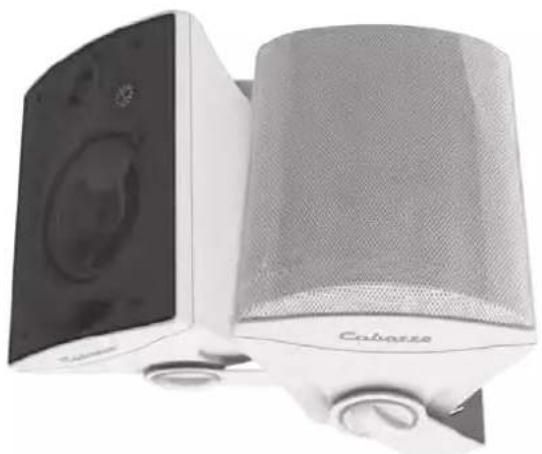
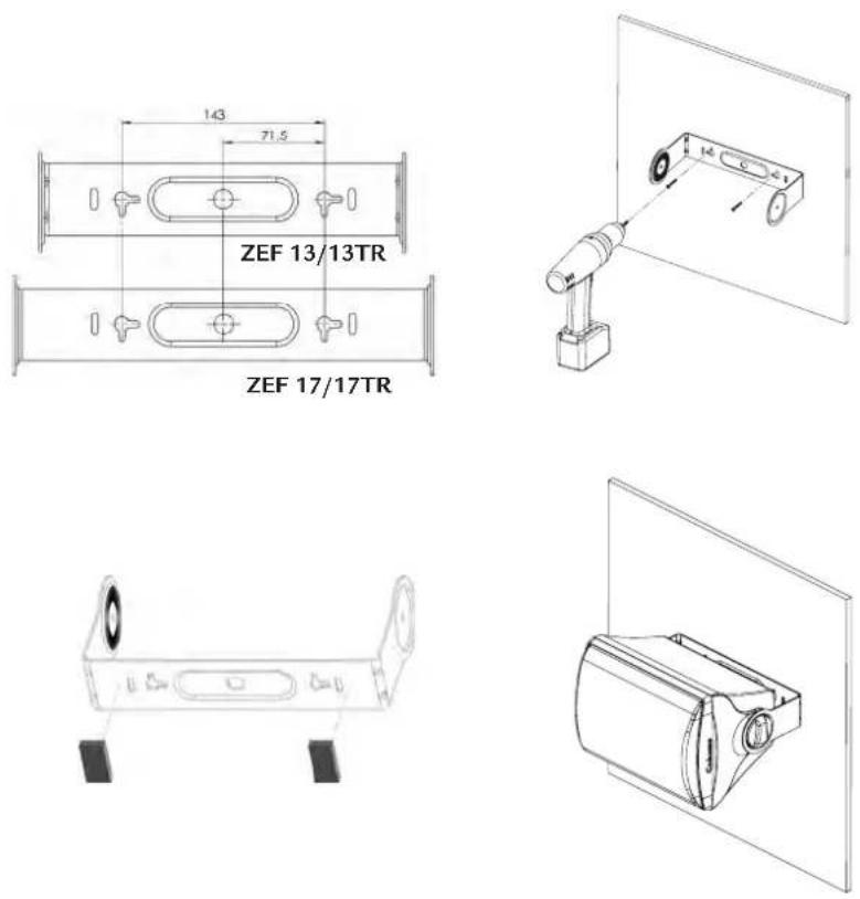
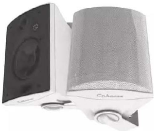
Black-and-white photo of Caliasso audio speakers with visible sound waves and coverings (no text or symbols on devices)MONTAGE MURAL VERTICAL - VERTICAL WALL MOUNT
SENKRECHTE WANDBEFESTIGUNG
①
natural_image
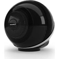
Line drawing of a modern kitchen appliance with a lid and base mount (no text or symbols)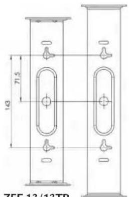
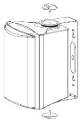
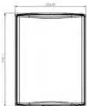
ZEF 13/13TR
natural_image
Technical line drawing of a mechanical device with a cylindrical component and a separate bracket (no text or symbols)ZEF 17/17TR
natural_image
Technical line drawing of a rectangular electronic device with mounting holes and a side panel (no text or symbols)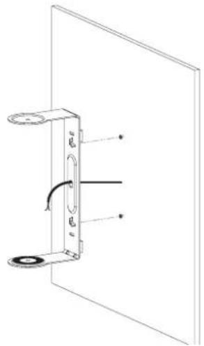
natural_image
Technical line drawing of a door handle assembly with mounting holes and a curved internal component (no text or symbols)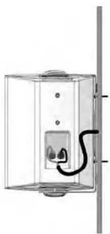
natural_image
Exterior view of a wall-mounted electrical outlet with a black cable inserted (no text or symbols visible)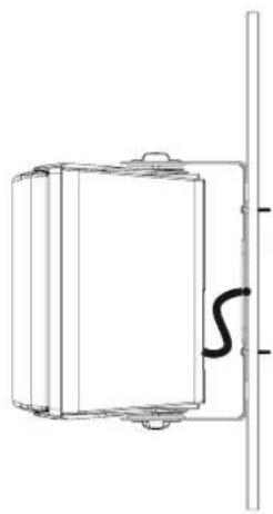
natural_image
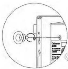
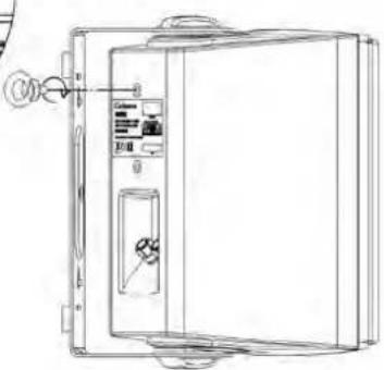
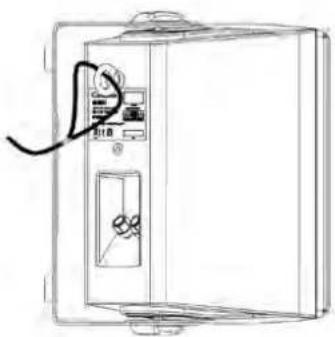
Pure technical line drawing of a mechanical component with no text or symbolsMONTAGE ANNEAU D'ANCRAGE ANTI-CHUTE
ASSEMBLY OF THE EYE BOLT FOR FALL PROTECTION
AUFBAU DES ABSTURZSICHERUNGS BOLZEN
natural_image
Line drawing of a refrigerator interior with a wall-mounted control panel and a cable (no text or symbols)MONTAGE MURAL HORIZONTAL - HORIZONTAL WALL MOUNT WAAGERECHTE WANDBEFESTIGUNG
②

ATTENTION!
For horizontal use, always position the Zef speaker with the Cabasse logo on the right hand side so that it reads from bottom to top, thus preventing risks of water intrusions inside the cabinet due to splashes.

ACHTUNG!
ZEF 13 TR
1) High impedance mode (100 V or 70 V) select the required power for each loudspeaker: 30W, 15W and 10 W for 100 V mode and 30 W, 15 W, 7.5 W, 5W for 70 V mode.
Attention! The Zef 13TR is originally set in 30W/100 V - 15W-70V position.
2) Low impedance mode: select the 4 Ω position
3) Off position: to be used when the loudspeaker should be off operation.
Leistungsschalter:
flowchart
graph TD
    A["DCAM"] --> B["Two cylindrical tanks"]
    A --> C["Two cylindrical tanks"]
    B --> D["Control panel"]
    C --> D
ZEF 17 TR
1) High impedance mode (100 V or 70 V) select the required power for each loudspeaker: 60W, 30W, 15 W and 10 W for 100 V mode and 30 W, 15 W, 7.5 W, 5W for 70 V mode.
Attention! The Zef 17 TR is originally set in 30W/100 V - 15W-70V position.
2) Low impedance mode: select the 4 Ω position
3) Off position: to be used when the loudspeaker should be off operation.
Leistungsschalter:
The connection in 70V/100V mode is only made in parallel.
Low impedance connection.
Normalimpedanz-Verbindung.
Attention aux chariots de manutention
AVEC LA FIXATION STANDARD ① ②
AVEC LA FIXATION EN OPTION ③
natural_image
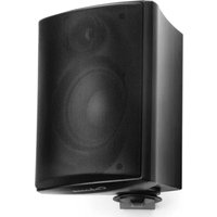
Close-up of a white audio/video studio speaker with a black cover and a gray headband, no visible text or symbols on the device.SPÉCIFICATIONS ET CARACTÉRISTIQUES TECHNIQUES
ZEF 13 - ZEF 13 TR
natural_image
Technical line drawing of a mechanical component with a circular top and flange (no text or symbols)ZEF 17 - ZEF 17 TR
natural_image
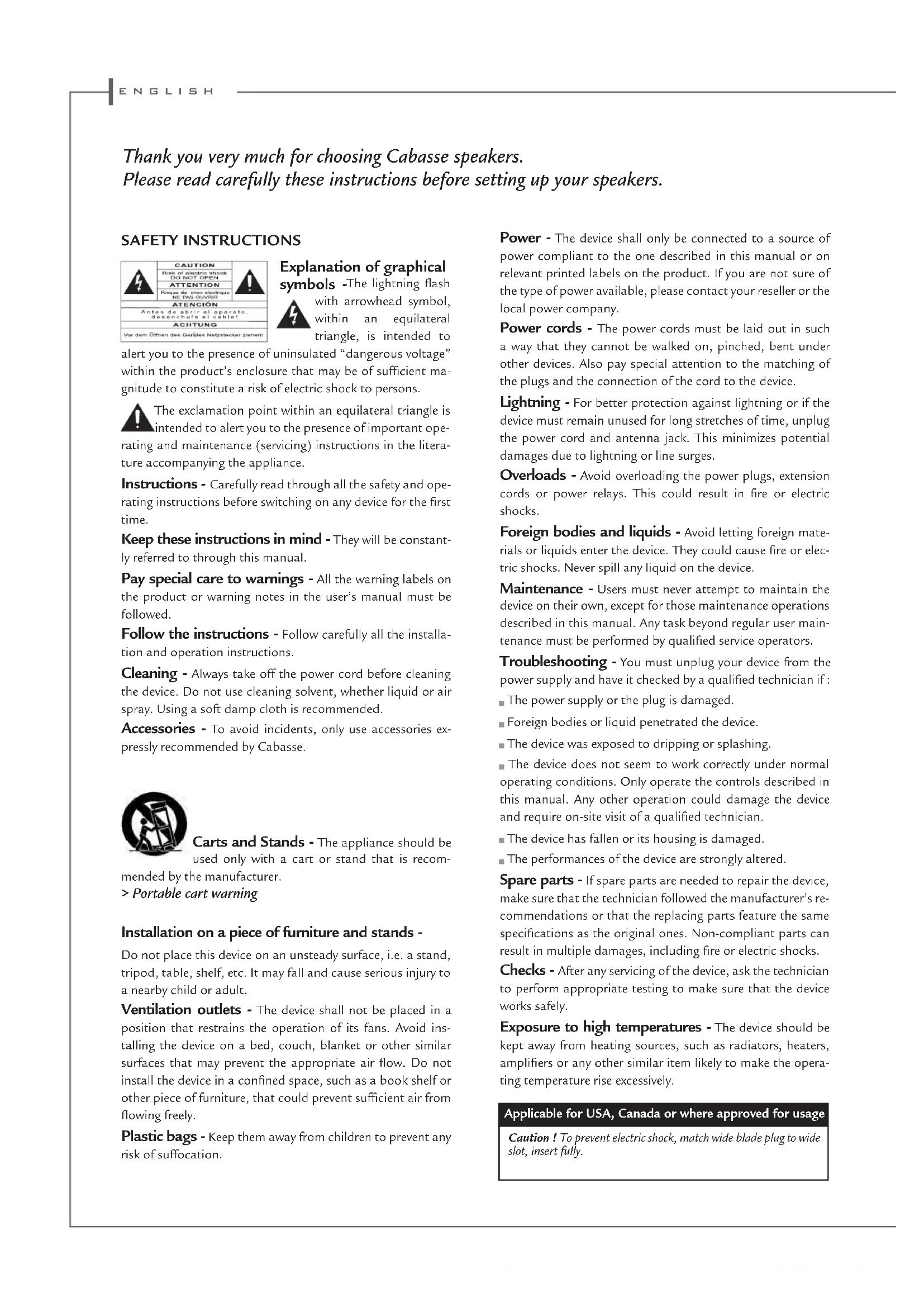
Technical line drawing of a mechanical component with no visible text or symbolsThank you very much for choosing Cabasse speakers.
Please read carefully these instructions before setting up your speakers.
SAFETY INSTRUCTIONS
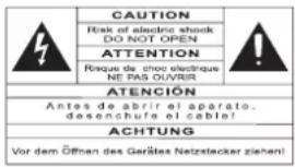
Explanation of graphical symbols -The lightning flash
with arrowhead symbol, within an equilateral triangle, is intended to
alert you to the presence of uninsulated “dangerous voltage” within the product’s enclosure that may be of sufficient magnitude to constitute a risk of electric shock to persons.
The exclamation point within an equilateral triangle is intended to alert you to the presence of important operating and maintenance (servicing) instructions in the literature accompanying the appliance.
Instructions - Carefully read through all the safety and operating instructions before switching on any device for the first time.
Keep these instructions in mind - They will be constantly referred to through this manual.
Pay special care to warnings - All the warning labels on the product or warning notes in the user's manual must be followed.
Follow the instructions - Follow carefully all the installation and operation instructions.
Cleaning - Always take off the power cord before cleaning the device. Do not use cleaning solvent, whether liquid or air spray. Using a soft damp cloth is recommended.
Accessories - To avoid incidents, only use accessories expressly recommended by Cabasse.
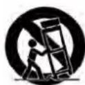
Carts and Stands - The appliance should be used only with a cart or stand that is recom-
mended by the manufacturer.
Portable cart warning
Installation on a piece of furniture and stands -
Do not place this device on an unsteady surface, i.e. a stand, tripod, table, shelf, etc. It may fall and cause serious injury to a nearby child or adult.
Ventilation outlets - The device shall not be placed in a position that restrains the operation of its fans. Avoid installing the device on a bed, couch, blanket or other similar surfaces that may prevent the appropriate air flow. Do not install the device in a confined space, such as a book shelf or other piece of furniture, that could prevent sufficient air from flowing freely.
Plastic bags - Keep them away from children to prevent any risk of suffocation.
Power - The device shall only be connected to a source of power compliant to the one described in this manual or on relevant printed labels on the product. If you are not sure of the type of power available, please contact your reseller or the local power company.
Power cords - The power cords must be laid out in such a way that they cannot be walked on, pinched, bent under other devices. Also pay special attention to the matching of the plugs and the connection of the cord to the device.
Lightning - For better protection against lightning or if the device must remain unused for long stretches of time, unplug the power cord and antenna jack. This minimizes potential damages due to lightning or line surges.
Overloads - Avoid overloading the power plugs, extension cords or power relays. This could result in fire or electric shocks.
Foreign bodies and liquids - Avoid letting foreign materials or liquids enter the device. They could cause fire or electric shocks. Never spill any liquid on the device.
Maintenance - Users must never attempt to maintain the device on their own, except for those maintenance operations described in this manual. Any task beyond regular user maintenance must be performed by qualified service operators.
Troubleshooting - You must unplug your device from the power supply and have it checked by a qualified technician if :
■ The power supply or the plug is damaged.
■ Foreign bodies or liquid penetrated the device.
■ The device was exposed to dripping or splashing.
The device does not seem to work correctly under normal operating conditions. Only operate the controls described in this manual. Any other operation could damage the device and require on-site visit of a qualified technician.
■ The device has fallen or its housing is damaged.
■ The performances of the device are strongly altered.
Spare parts - If spare parts are needed to repair the device, make sure that the technician followed the manufacturer's recommendations or that the replacing parts feature the same specifications as the original ones. Non-compliant parts can result in multiple damages, including fire or electric shocks.
Checks - After any servicing of the device, ask the technician to perform appropriate testing to make sure that the device works safely.
Exposure to high temperatures - The device should be kept away from heating sources, such as radiators, heaters, amplifiers or any other similar item likely to make the operating temperature rise excessively.
Applicable for USA, Canada or where approved for usage
Caution! To prevent electric shock, match wide blade plug to wide slot, insert fully.
ZEF 13 - ZEF 13 TR - ZEF 17 - ZEF 17 TR
UNPACKING ①
After opening the top carton flaps, fold the carton flaps right back, remove the cardboard sheet, the foam halfshells protecting the speakers. Then pull out the speakers and the accessories. We suggest you to retain the packing for future use.
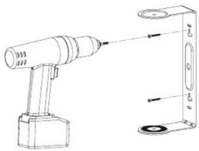
WALL MOUNT WITH THE STANDARD YOKE BRACKET
1) Prepare all the necessary parts and tools: the yoke bracket, and the screws, plugs and drilling equipment suitable for the type of wall and a spirit level.

Be assured that the wall can handle the weight of the loudspeaker and that the selected plugs do suit with the wall characteristics.
2) Position the bracket on the wall at the chosen spot, check the up and down orientation, check it is with the spirit level aligned and drill 2 holes through the bracket holes. Insert the plugs in the wall.
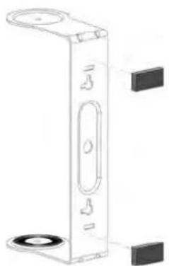
3) Place the damping stickers on the back of the bracket and mount the bracket with right screws.
4) Fit the loudspeaker into the arms of the bracket, gently hand tighten both knobs.
5) Connect the loudspeaker cable to the terminals. Ensure that polarities are correct (see § Phase).
6) Swivel the loudspeaker to the right angle and tight both nobs.
WALL MOUNT WITH THE OPTIONAL BALL BRACKET
1) Prepare all the necessary parts and tools: the ball bracket and screws, plugs and drilling equipment suitable for the type of wall and a spirit level.
2) Mount the bracket part with two holes on the back of the loudspeaker, place the other part of the bracket on the wall and use it as a drilling template, control the alignment and drill the holes through the bracket. Place the inserts in the holes.
3) Assemble both bracket parts, swivel the loudspeaker in the right direction and tighten the bolt.
4) Connect the loudspeaker cable to the terminals. Ensure that polarities are correct (see § Phase).
OUTDOOR MOUNT

ATTENTION : Direct long exposure to sunshine or bad weather can affect the look of you loudspeakers. We recommend the mounting under a canopy for fair weather periods followed by removal and storage in winter.
When used horizontally outside or in humid environment, be assured that the loudspeaker is positioned as shown on page ③ with the Cabasse logo on the right hand side.
Optimal positioning for a 2.0 or stereo system
If «d» is the distance between the two speakers, this distance must be higher than 5 ft (1.5 m) and the two speakers must be at equal distance from the listening area which forms with them an equilateral triangle.
■The drivers must be directed towards the listening area.
The speakers should be located so that their diffusion follows the longest dimension of the room.
■Generally speaking it is better to avoid putting the speakers in the corners of a room as this amplifies the low frequencies and tends to enhance the room resonances.
- Placing the speakers in niches is not recommended. Unless designed for this application, bookshelf placement will alter the frequency response of the speaker, especially in the low frequencies. If a bookshelf location cannot be avoid, the speaker should be set up to minimize various resonance, and the visible part of the grille must be outside the niche.
WEEE MARK
Disposal of Wastes of Electrical & Electronic Equipment (Applicable in the European Union)
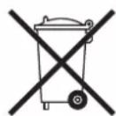
This symbol on the product, consisting of the crossed-out wheeled bin, indicates that this product shall not be treated as household waste. Instead it shall be handed over to the applicable collection point for the disposal of electrical and electronic equipment at the end of life. By ensuring this product is disposed of correctly, you will help prevent potential negative consequences for the environment and human health, which could otherwise be caused by inappropriate waste handling of this product. The recycling of materials will help to preserve natural resources. For more detailed information about recycling of this product, please contact your local city office, your household waste disposal service or the shop where you purchased the product.
CONNECTION
Cable section
To get the full sonic potential of Cabasse loudspeakers and avoid over 15% power losses, the cables connecting the speakers to the power amplifier must have the lowest possible electrical resistance. Follow the here-under diagrams to select the minimum correct cable gauge for your high impedance installation.
Cable length/section for 4 ohms versions
(One speaker per amplifier output)
| Max amp-speaker Distance Cable Section | |
| 4.5 m 1.5 mm | ^2 |
| 6 m 2 mm | ^2 |
| 7.5 m 2.5 mm | ^2 |
| 9 m 3 mm | ^2 |
| 12 m 4 mm | ^2 |
Maximum LS cable length for 100 V mode
| Length (m) Power (W) | ||||
| 30 | 60 | 120 | 240 | |
| 20 | 0.75mm^2 | 0.75mm^2 | 0.75mm^2 | 0.75mm^2 |
| 50 | 0.75mm^2 | 0.75mm^2 | 0.75mm^2 | 0.75mm^2 |
| 100 | 0.75mm^2 | 0,75mm^2 | 0.75mm^2 | 1mm^2 |
| 200 | 0.75mm^2 | 0.75mm^2 | 1mm^2 | 1.5mm^2 |
| 400 | 0.75mm^2 | 1mm^2 | 1.5mm^2 | 2mm^2 |
| 600 | 1mm^2 | 1.5mm^2 | 2mm^2 | 2.5mm^2 |
| 800 | 1mm^2 | 1.5mm^2 | 2mm^2 | 3mm^2 |
| 1000 | 1.5mm^2 | 2mm^2 | 2.5mm^2 | 4mm^2 |
Maximum LS cable length for 70 V mode
| Length (m) Power (W) | ||||
| 30 | 60 | 120 | 240 | |
| 20 | 0.75mm^2 | 0.75mm^2 | 0.75mm^2 | 0.75mm^2 |
| 50 | 0.75mm^2 | 0.75mm^2 | 0.75mm^2 | 1mm^2 |
| 100 | 0.75mm^2 | 0.75mm^2 | 1mm^2 | 1.5mm^2 |
| 200 | 0.75mm^2 | 1mm^2 | 1.5mm^2 | 2mm^2 |
| 400 | 1mm^2 | 1.5mm^2 | 2mm^2 | 3mm^2 |
| 600 | 1.5mm^2 | 2mm^2 | 2.5mm^2 | 4mm^2 |
| 800 | 1.5mm^2 | 2mm^2 | 3mm^2 | 4mm^2 |
| 1000 | 2mm^2 | 2.5mm^2 | 4mm^2 | 6mm^2 |
Phase
In order to maintain the phase relationship and frequency balance of the loudspeaker system, both loudspeakers must be properly connected to the power amplifier. When properly connected, the cones of the drivers of both loudspeakers will move in the same direction when driven by identical signals. If the cones move in opposite directions, the resulting out of phase signals will create a perceptible power loss, particularly in the low frequencies. The stereophonic message will also be degraded. Amplifier and speaker manufacturers typically indicate connection polarity in one of two ways: red and black or plus and minus. In either case, always connect red or plus to red or plus and black or minus to black or minus. Connections should be identical for both channels. To check that the speakers are in correct phase, switch the system to mono while music is being played. if the amplifier does not have a phase inversion switch, it will be necessary to change over the connections on one only of the loudspeakers. If in correct phase, the image should be distinctly located between the loudspeakers with a slight loss of bass and low midrange level. If the image is confused and not centrally located and there is a drastic loss of bass and low midrange level, recheck your connections.
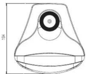
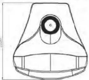
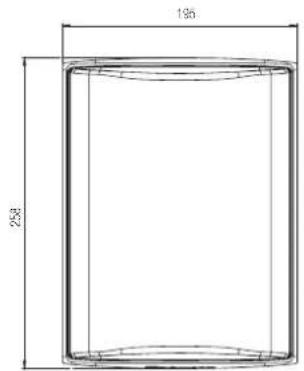
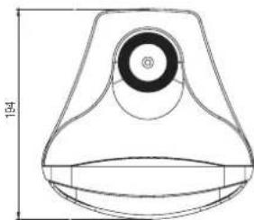
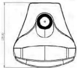
ZEF 13 - ZEF 13 TR
natural_image
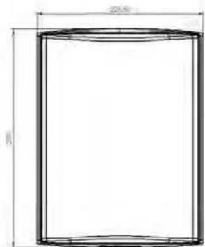
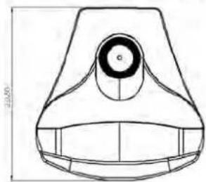
Technical line drawing of a conical mechanical component with a central circular feature and top dimension labeled 194 (no text or symbols beyond measurement lines)ZEF 17 - ZEF 17 TR
natural_image
Technical line drawing of a mechanical component with no visible text or symbolsSPECIFICATIONS & TECHNICAL DATA
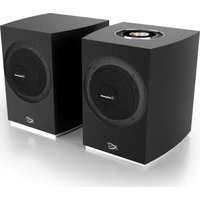
natural_image
Two desktop audio speakers, one black and one white, with no visible text or symbols on the speaker surfaces.| ZEF 13 ZEF 17 | ||
| Use | on wall on wall | |
| Ways | 2 | 2 |
| Drivers | 1 x DOM25 tweeter1 x 13T15AWmidrange woofer | 1 x DOM25 tweeter1 x 17T15AWmidrange woofer |
| Efficiency1W/1m | 86 dB 89 dB | |
| Cross-over point | 3,700 Hz 4,000 Hz | |
| Frequency response | 70-22,000 Hz 67 - 22,000 Hz | |
| Nominal impedance | 4 ohms 4 ohms | |
| Minimum impedance | 4 ohms 3.7 ohms | |
| ZEF 13 TR - ZEF 17 TRTransformer taps(rotary switch on the frontbaffle behind the grill) | 70 V: 30 W / 15 W / 7,5 W /5 W / OFF100 V: 30 W / 15 W /10 W / OFF | 70 V: 30 W / 15 W / 7,5 W /5 W / OFF100 V: 60 W/ 30 W / 15 W /10 W / OFF |
| Power handling | 60 W 90 W | |
| Peak power | 420 W 630 W | |
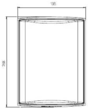
| Standard finish | white - black white - black | |
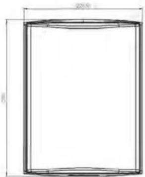
| Dimensions H x W x D | 285 x 195 x 194 mm10.2 x 7.7 x 7.6 in | 299 x 227 x 234 mm10.2 x 7.7 x 7.6 in |
| Weight | Zef 13: 3.2 kg - 7 lbsZef 13TR: 3.9 kg - 8.6 lbs | Zef 17: 4.5 kg - 9.9 lbsZef 13TR: 5.1 kg - 11.2 lbs |
Because of technical improvements already under way in our constant search for optimum quality, Cabasse reserves the right to modify all the models presented in specification sheets, advertising materials and manuals without prior notice.
natural_image
Technical line drawing of a mechanical component with a circular top and flange (no text or symbols)ZEF 17 - ZEF 17 TR
natural_image
Technical line drawing of a mechanical component with no visible text or symbolsTECHNISCHE DATEN