
FT1000e - Industrial dishwasher Hobart - Free user manual and instructions
Find the device manual for free FT1000e Hobart in PDF.

| Product Type | Industrial conveyor dishwasher (flight-type) |
| Brand | Hobart |
| Model | FT1000e |
| Dimensions (center section) | 8 ft (2438 mm) long |
| Approximate weight | 2000 kg (depending on configuration) |
| Power supply | Three-phase, 200-240 V, 50/60 Hz (other voltages available) |
| Required water pressure (hot) | 30-45 psig (depending on model) |
| Steam pressure (if equipped) | 12-45 psig |
| Minimum incoming water temperature | 110 °F (43 °C) for fill and final rinse (basic models) |
| Wash functions | Prewash, wash, pressure rinse, double rinse/final rinse |
| Additional options | Fan dryer, energy recovery, automatic soil removal (ASR), automatic cleaning, automatic descaling |
| Conveyor type | Link conveyor belt with scrapers |
| Chamber material | Stainless steel |
| Routine maintenance | Cleaning of line filters, checking spray nozzles, conveyor maintenance |
| Descaling | Built-in decalcification indicator based on water hardness |
| Safety | Door and drain safety switches, motor overload protection, lockout/tagout |
| Connections | Water: NPT 1 in (fill); Steam: NPT 1 1/2 in; Drain: NPT 2 in |
| Common spare parts | Retaining rings, O-rings, spray nozzles, conveyor bearings, belts |
| Repairability | Removable panels, electrical diagrams available, Hobart after-sales service |
Frequently Asked Questions - FT1000e Hobart
User questions about FT1000e Hobart
0 question about this device. Answer the ones you know or ask your own.
Ask a new question about this device
Download the instructions for your Industrial dishwasher in PDF format for free! Find your manual FT1000e - Hobart and take your electronic device back in hand. On this page are published all the documents necessary for the use of your device. FT1000e by Hobart.
USER MANUAL FT1000e Hobart
natural_image
Exterior view of a modern industrial machine with control panel and conveyor system (no visible text or symbols)HOBART
701 S. RIDGE AVENUE
TROY, OHIO 45374-0001
937 332-3000
www.hobartcorp.com
F41144 (December 2019)
TABLE OF CONTENTS
NOTES FOR THE INSTALLERS 4
HOW TO REDUCE THE CLEARANCE HEIGHT OF THE CONTROL BOX DURING MOVE-IN....4
HOW TO REMOVE ENERGY RECOVERY/VENT HOUSING FOR LOW CLEARANCE 6
UNPACKING 7
Removing Each Section From Its Skid 7
LOCATION 8
Positioning the Center Section 8
Leveling the Center Section 8
ASSEMBLY 9
Rotating Control Box 90 Degrees 9
Installing Foam Tape on Chamber Flanges & Control Box Mounting Surface 9
Attaching Control Box to Unload Section 10
Positioning the Adjacent Load or Unload Sections 12
Leveling the Load and Unload Sections 12
Joining the Sections Together....12
Installing the Curtain Hangers and Unload Air Baffle 13
Installing the Saddle Joint – Bottom of Chamber Flanges 14
Installing the Flowback Pipe (Wash to Prewash Tanks) 15
Installing the Drain Pipe 15
Relocating Master Drain to Load End (Only Machines Equipped with Auto Clean,
Auto Delime, & the ASR Section) 16
Drain Back Pan Installation....20
Blower Dryer Assembly 21
Advansys Module Installation 23
Control Box Connections 23
Electric Booster Heater Wiring 24
Door and Drain Interlock Switches (Prewash to Wash Tank) 24
PLUMBING CONNECTIONS....25
Water Supply 25
Fill 25
Final Rinse 25
Drain 26
Line Strainers 26
Steam Supply (When Equipped). 26
Steam Tank Heaters – Condensate Return Lines....27
Steam Booster Heater – Condensate Return Line & Relief Valves 27
Steam Blower Dryer (When Equipped) - Condensate Return Line 27
Fill & Auto Clean (When Equipped) Hose Connections 27
ELECTRICAL CONNECTIONS 30
Motor Overloads 30
Checking Motor Rotation (Three-Phase Motors) 31
Separate Electrical Connections....31
Voltage Adjustment 31
Electrical Connection – Detergent & Rinse Aid Dispensers 32
External Vent Fan Control....32
CONVEYOR ASSEMBLY 33
Loading and Joining the Conveyor Sections....33
Conveyor Offset Side Bar 36
Adjusting the Conveyor Take-Up Unit (Load Section)....37
FT1000e Conveyor Jam Switch Setting Verification/Adjustment 38
MISCELLANEOUS....40
Vent....40
Air Baffle Settings 40
Curtain Configurations 44
Prewash, Wash, and Power Rinse Arms 53
Dual Rinse/Final Rinse Arms 53
Automatic Soil Removal (ASR) Arms (When Equipped) 54
Lower Trim Panels (Front) and Rear Panels. 54
Calibrating the Electric Booster Thermostat 55
Conveyor Gear Motor 55
Delime Indicator Setup 55
SERVICE 55
Installation and Care Of FT1000e SERIES DISHWASHERS SAVE THESE INSTRUCTIONS
GENERAL
NOTES FOR THE INSTALLERS
Read the entire manual before installing the machine.
- Do not use a forklift to move or unskid machine sections.
- Do not throw out any loose parts. These may be required for installation or operation.
-
Electrical Connections:
-
Make sure line voltage matches the machine data plate located on the control box.
- Make sure wiring connections to terminal block match the diagram inside the control box door.
-
Make sure the pilot circuit transformer is set to the correct voltage. Refer to Voltage Adjustment, page 31.
-
Level the center section in operation position. Center section must be level end to end and front to back. Refer to Leveling the Center Section, page 8.
-
Conveyor: Refer to the Conveyor Assembly section, page 33. After installation, the conveyor must run continuously for 15 minutes and then be checked for alignment. Adjust if necessary and rerun for another 15 minutes. Then recheck alignment and retighten locknuts on take-up unit when finished.
-
Make sure all curtains are in proper operating positions. Refer to Curtain section, pages 44-52.
-
Check all water and steam unions for tightness.
-
Regarding drain installation, make sure that drain piping is free of any leaks.
-
Give the Operation Manual to the owner.
HOW TO REDUCE THE CLEARANCE HEIGHT OF THE CONTROL BOX DURING MOVE-IN
This procedure will reduce the overall height of the control box by 4-1/2" to allow it to travel through a low-height corridor or doorway.
⚠ WARNING The control box must be securely supported by at least two people while its mounting studs are being shifted to lower slots of the shipping braces.
The rear of the main control box is attached to the two shipping braces on the dual rinse/final rinse section by four 5/16-18 threaded studs, washers, lock washers, and nuts. The shipping braces have slots that allow the control box to be lowered by 4-1/2" (Fig. 1).
- Remove the two shipping hinges from the side of the control box by removing the two 5/16-18 bolts from each bracket.
- While two people are securely supporting the main control box, remove the four 5/16-18 nuts, lock washers, and washers from the inside of the shipping braces behind the control box.
- Using at least two people, CAREFULLY withdraw the main control box's rear studs from the shipping braces. Lower the control box threaded studs to the lower slots on the braces. Refasten the control box with the same 5/16-18 nuts, lock washers, and washers removed in step 2.
- Move the dishwasher past all low-height corridors or doorways.
- Reverse steps 3, 2, and 1 to return the main control box to its original shipping condition for proper installation.
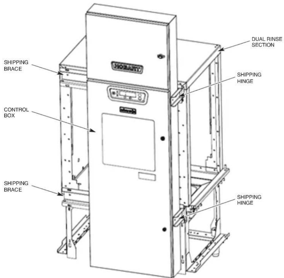
Fig. 1
HOW TO REMOVE ENERGY RECOVERY/VENT HOUSING FOR LOW CLEARANCE
- Remove the front and rear energy recovery panels by loosening the two nuts on top of each panel (Fig. 2, item A).
- Remove the drain pan located in the base of the energy recovery assembly (Fig. 2, item B).
- Remove the three stop nuts located in the corners which secure the energy recovery assembly to the top of the dual rinse chamber.
- Lift the energy recovery assembly straight up until the base clears the top of the studs and remove the assembly from the top of the machine.
- Once the center section is moved into the dish room, reinstall the energy recovery assembly, drain pan, and front and rear panels. NOTE: Apply permagum to washers when reinstalling.
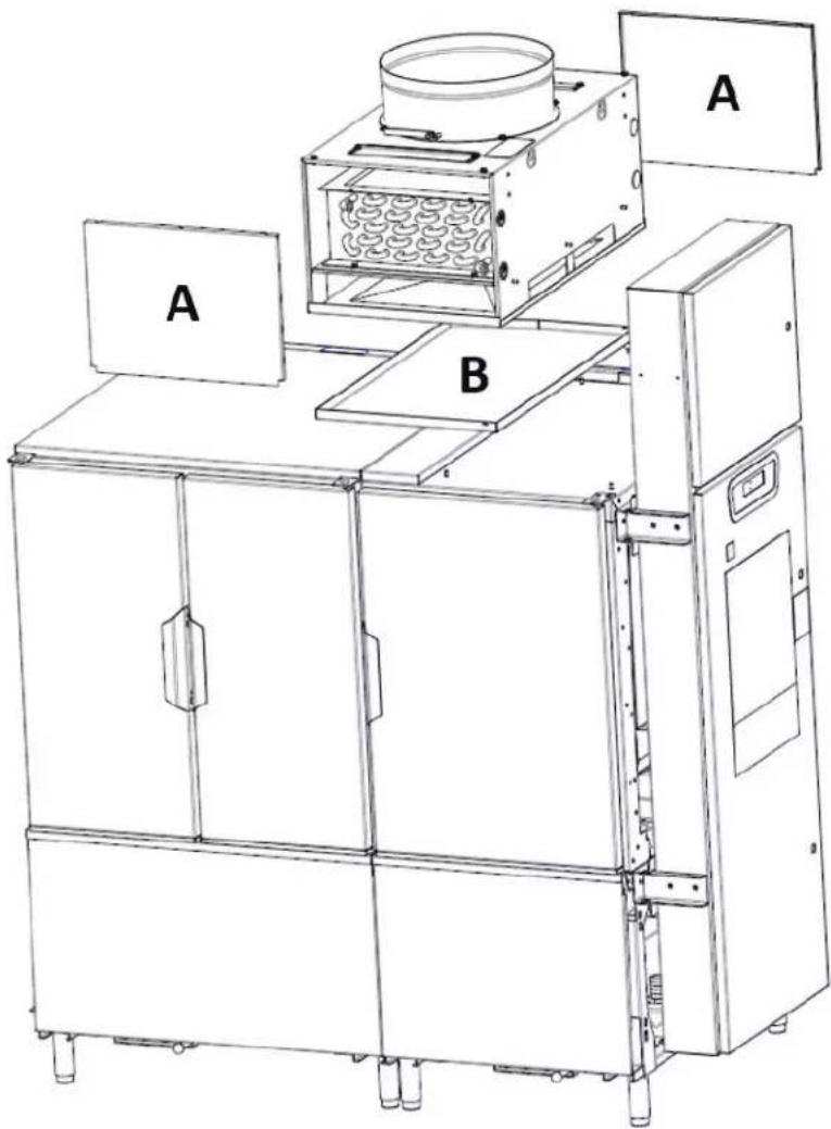
natural_image
Technical line drawing of an industrial machine with labeled components A and B (no text or symbols beyond labels)Fig. 2
UNPACKING
Immediately after unpacking the dishwasher, check for possible shipping damage. If the machine is found to be damaged, save the packaging material and contact the carrier within 5 business days of delivery.
Before installation, test the electrical service to make sure it agrees with the specifications on the machine data plate located on the control box. The electrical diagram is located inside the control box.
Strainer baskets, strainer pans, pump inlet strainers and wash arms are taped and shipped in place. Remove tape, but retain parts in their proper places. If any parts are temporarily removed during installation, return to their proper places after installation is complete.
Before installing, check to make sure that necessary electrical, plumbing and exhaust accommodations are provided at the installation location. Take measurements of site's plumbing, electrical and exhaust connections; then take corresponding measurements of the machine to make sure all connections are correctly mated. If necessary to lower control box during move-in, slotted holes are provided on the control box shipping braces to allow adjustment for clearance height. Refer to page 4.
Removing Each Section From Its Skid
NOTICE Do not use a forklift directly on the machine frame or tank to move or lift machine sections. Doing so may result in damage to the machine.
- Using a forklift or pallet jack, raise one end of the skid and unthread the feet from the legs as far as possible without removing the foot from the leg. Repeat for other end until all feet have been extended out. Lower the skid back to the floor. This will now allow the machine to sit on its feet so the skid can easily be removed.
- Remove the two end plate screws from the 2x4 runners, located just inside the front and rear legs, at each end of the skid.
- Remove all lag bolts from the top of the skid cross members along either the front or rear of the machine.
- From the opposite side of the machine that the lag bolts were removed in step 3, pull the entire skid assembly out from beneath the machine section.
- Thread the feet into the legs as far as possible; then back out three full turns. Standard legs have 3" threaded studs for maximum adjustment. If special feet were ordered with extra-long leg shanks to accommodate a highly sloped floor, install them where the low points in the floor occur at leg locations on the machine before setting the unit on the floor.
-
Open all inspection doors and remove all wrapped parts and boxes from inside each machine section.
-
Remove and packaging, tape, wire and bracing from each section. Remove all rear and lower panles.
-
Verify that shipping tape has been removed from all floats in each tank and that the floats are free to operate properly.
NOTE: Do not throw out any loose parts. These may be required for installation or operation. Verify all ship loose items have been received per the packing list.
LOCATION
Allow adequate space for machine installation and operation. Place the machine sections close to their final position. Allow space to work on the ends of the center section.
Review, but do not remove tags or labels. Remove tags after installation is complete.
Positioning the Center Section
Use a chalk line on the floor to align the machine along its complete length.
With each section in its approximate final position, determine which section is at the high point in the floor. Machine assembly begins after the center section has been leveled to a height that compensates for the floor height of the other sections.
Leveling the Center Section
Leveling is an important installation function because it could affect door operation and cause leaks once the machine is operating.
- Level the center section along its length by opening the doors and placing a level between the doors along the tank support rail (Fig. 3). Do not check level on top of doors. Adjust the feet in or out as required to level.
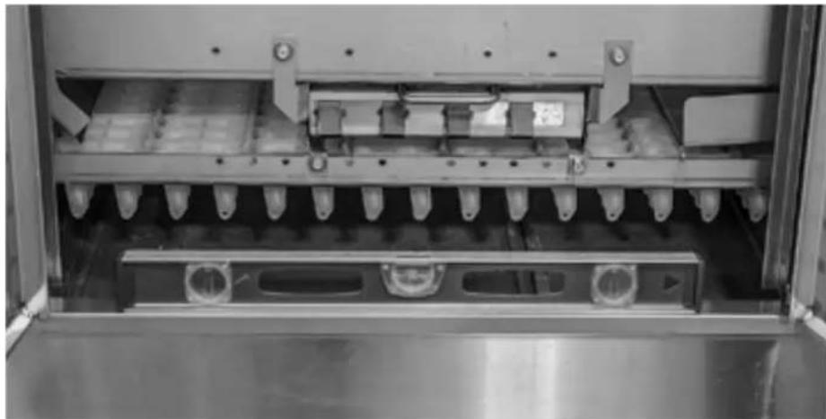
natural_image
Interior view of a stainless steel industrial machine with multiple vials and cooling fins (no visible text or symbols)Fig. 3
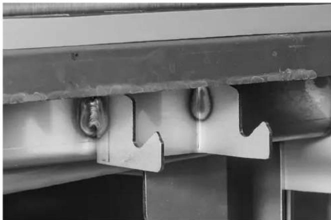
- Continue to level the center section front to back by removing the top panels and placing level across the top of the chambers on both ends of center section (Fig. 4).
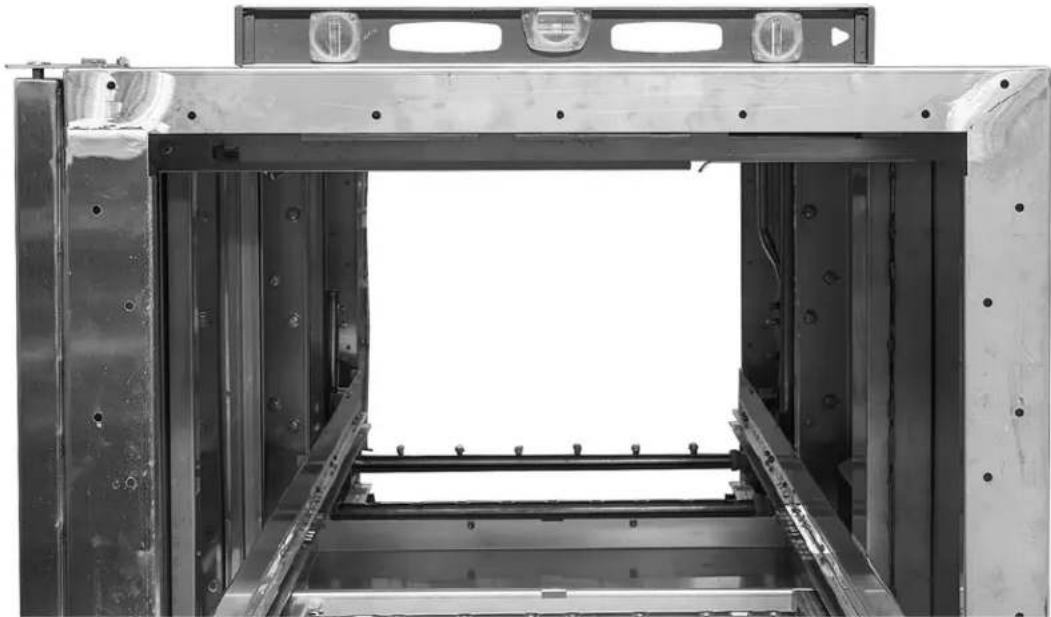
natural_image
Interior view of a large industrial machine or enclosure with metal frame and mounting holes (no visible text or symbols)Fig. 4
ASSEMBLY
Rotating Control Box 90 Degrees
The main control box is shipped with the upper and lower shipping hinges connected to the side of the control box. Remove the four 5/16-18 nuts, lock washers, and washers from the inside of the shipping braces behind the control box. Use the shipping hinges (Fig. 1) to rotate the control box 90 degrees. Do not remove the shipping hinges until after the control box is secured to the unload section.
Pull the control box out to allow mating of center and unload sections without interference with studs projecting from rear of control box.
Installing Foam Tape on Chamber Flanges & Control Box Mounting Surface
Cut strips of vinyl foam tape to fit the top, bottom, and vertical sides of the chamber flanges on the end of the load and unload sections to make a good seal. Apply strips of foam tape to the vertical edges of the chamber ends, across the top of the chamber ends, and one strip across the bottom flanges (Fig. 5). Place the foam tape approximately 1/16"-1/8" from the outside edge of the chamber. After the foam tape is applied, trim the excess tape along the chamber edges.
NOTE: The vertical piece of foam tape on the outer edge at the front of the machine must be folded over 12 " on the sticky side with the rolled edge of the tape positioned towards the front of the machine.
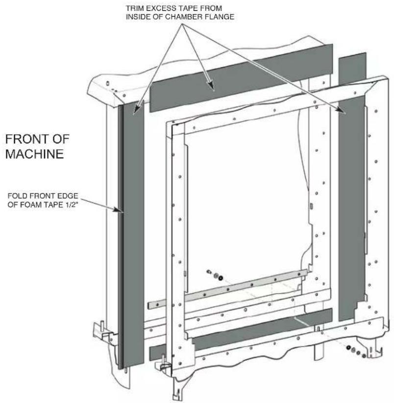
Fig. 5
Apply foam tape to unload chamber section where the rear perimeter of the control box will be mounted.
Attaching Control Box to Unload Section
- Remove hardware from front and rear detachable legs. DO NOT RE-INSTALL HARDWARE UNTIL AFTER SECTIONS ARE JOINED.
- Remove the detachable leg section on the front leg of the unload section where the control box will be mounted. This will allow the wires, which are preinstalled in the control box, to pass by the leg assembly freely (Fig. 6).
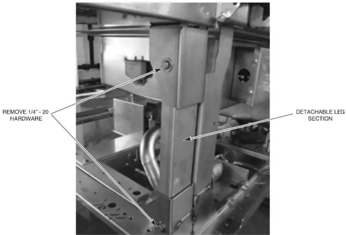
Fig. 6
- With the control box rotated 90 degrees, move the unload section to within several inches of the center section behind the control box.
NOTE: Ensure wires do not get pinched between sections.
-
Maneuver the unload section so that the four 5/16-18 threaded studs on the back of the control box protrude thru the mounting holes on the unload section.
-
Reinstall the detachable leg section removed in step 1 (without hardware).
-
Secure the control box to the unload section using four 5/16-18 nuts, lock washers, and washers.
-
Once the control box is secured to the unload section remove the two shipping hinges from the side of the control box by removing the two 5/16 bolts and associated hardware from each hinge. The control box is now part of the unload section.
-
Install two 5/16 round head screws in open holes of control box where shipping hinges were removed.
-
Remove the hinges from the shipping braces by removing the cotter pins and hinge pins.
-
Remove the two shipping braces from the end of the dual rinse section by removing the three 5/16 bolts and associated hardware from each brace.
Positioning the Adjacent Load or Unload Sections
Move the adjoining (load or unload) section to within several inches of the prepared end of the center section. Adjust the feet of the section adjacent to the leveled center section so tank supports are the same height. Peel the protective paper from the vinyl foam tape and move the second section to its final position. Be very careful that mating components connect and fit together properly.
Leveling the Load and Unload Sections
The tank support rails should be level across the entire length of the machine (Fig. 3). Sections to be mated should be level front to back (Fig. 4).
- All adjoining components of the two sections are exactly in line with each other.
- Top corners of adjoining sections are the same height.
Joining the Sections Together
Use drift pins to align the holes in the horizontal and vertical chamber flanges of the mated sections. Use C-clamps to hold the sections in position while bolting the chamber front and back flanges together. Exercise care to avoid tearing the foam tape seal.
NOTICE Do not use a forklift directly on the machine frame or tank to move or lift machine sections. Doing so may result in damage to the machine.
Secure the vertical frame corner posts together at two locations using the appropriate hardware (Fig. 7).
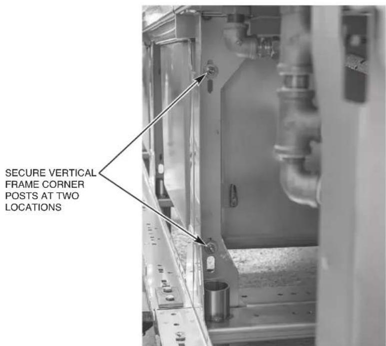
Fig. 7
Installing the Curtain Hangers and Unload Air Baffle
On prewash/wash section joint, install the two curtain hangers on the prewash side of the joint in the upper front and rear corners using the appropriate chamber flange hardware (Fig. 8).
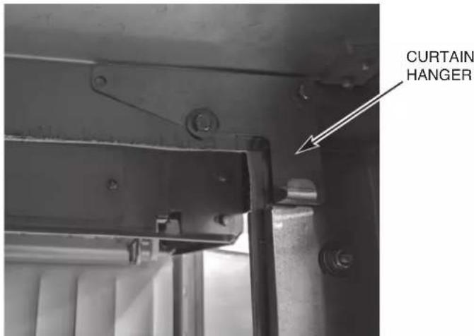
Fig. 8
On dual rinse/unload section joint, install the unload air baffle and two curtain hangers. The curtain hangers mount on to the air baffle studs where they protrude through the upper front and rear corner chamber holes on the final rinse side of the top of the chamber where sections are being joined using appropriate fasteners (Fig. 9). The unload air baffle also has three mounting holes which need to slip over the three studs protruding down from the top of the unload chamber. Secure with 14 -20 nuts, lock washers, and washers (Fig. 10).
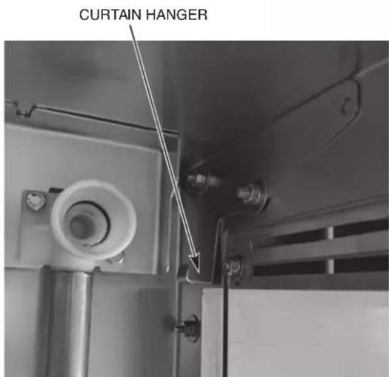
Fig. 9
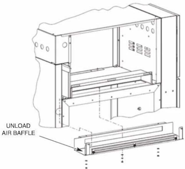
Fig. 10
CHAMBER FLANGE AND BOLT ASSEMBLY AT EACH SECTION JOINT
| Description Qty. Bolt | Size Assembly Order | Instructions | ||
| Short Bolt-Use except where long bolts or medium bolts are required | 22 1⁄4-20 x 5/8" [Bolt, Washer] [Washer, Lockwasher, Nut] | Use permagum on insides of washers on both sides of chamber flanges. | ||
| Medium Bolt-Use for curtain hangers and at top and bottom corners of chambers | 9 1⁄4-20 x 3/4" [Bolt, Washer] [Washer, Lockwasher, Nut] | Use permagum on insides of washers at curtain hangers and chamber flanges. | ||
| Long Bolt-Use on saddle joints, track/chamber interface, and vertical frame corner posts | 15 | 1⁄4-20 x 1" | [Bolt, Washer] [Washer, Lockwasher, Nut] | Use permagum on insides of washers on both sides of saddle joints and at tracks & chamber flanges. |
Installing the Saddle Joint - Bottom of Chamber Flanges
- Seal the tank end flanges where sections join together using a saddle joint.
- Position the saddle joint over the tank end flanges and make sure that all bolt holes are aligned. Use drift pins (or punches) to align holes if required.
- If machine is equipped with the standard conveyor assembly, install baffles along with the saddles using same mounting hardware. Ensure baffles are adjusted to the lowest position to ensure that the baffle does not interfere with the flight links (Fig. 11).
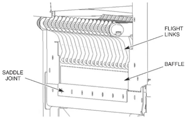
Fig. 11
- Use Permagum on insides of washers on both sides to make an adequate seal (Fig. 12). You may have to use a C-clamp on the saddle to get the hardware started. Bolt the saddle joint to the bottom tank flanges with seven long bolts, washers, lock washers, and nuts provided.
NOTE: Do not apply foam tape or permagum inside saddle or on surfaces that the saddle covers.
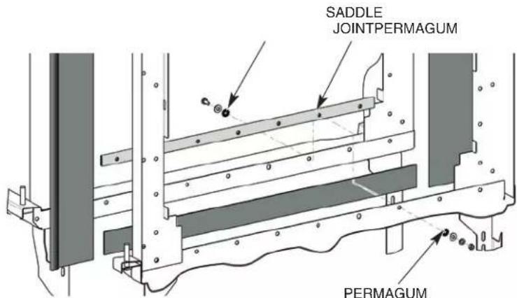
Fig. 12
Installing the Flowback Pipe (Wash to Prewash Tanks)
Install the flowback pipe between the wash tank and the prewash tank (Fig. 13).
Make sure the flowback pipe is adequately lubricated with O-ring lube (not supplied). Make sure O-rings are in their proper places on the coupling; two inside and one on the flange end.
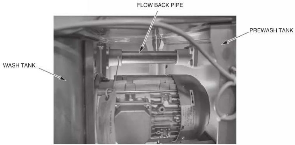
Fig. 13
Installing the Drain Pipe
Install the drain pipe between the adjoining tank sections as follows:
- Lubricate the molded drain T-connectors at each end of the drain pipe using O-ring lube (not supplied). Do not use animal-, vegetable-, or petroleum-based lubricants.
- With a twisting motion, slide the pipe into one of the molded drain T-connectors.
- Lift the other end, align it with the molded drain T-connectors and with a twisting motion, slide the pipe until the drain pipe hits the stop in the tee (approximately 1-1/4" from the face of the tee).
- Slide hose clamps to ends of drain pipe and tighten to maintain position.
Relocating Master Drain to Load End (Only Machines Equipped with Auto Clean, Auto Delime, & the ASR Section)
NOTE: If the dish machine is equipped with the Auto Clean and Auto Delime features, but does not contain the ASR section, then the Master Drain assembly must remain located at the unload end of the machine. With this configuration, if the customer's drain is located at the load end of the machine, then the drain will need to be plumbed from the unload end back to the customer's drain in the field.
If the installation requires the machine to be drained to the load end, the master drain assembly will need to be relocated as follows:
- Remove drain handle support bracket by removing the two bolts and associated hardware located on the bottom side of the frame channels. The support bracket may be discarded; however, retain the hardware removed for reassembly on the load end.
- Remove drain handle weldment by removing M12-1.5mm nut located at the bottom of the drain assembly. Remove magnet retainer and magnet from drain handle weldment and retain the nut, magnet retainer, magnet, and associated hardware for reassembly on the load end. The drain handle weldment may now be discarded.
- Remove D.I.N. connector from master drain solenoid valve and remove drain interlock switch from bracket securing it to the unload master drain platform. Retain all hardware for use on load end platform.
- Remove three bolts securing master drain assembly platform from bottom of frame channels.
- Slide platform and master drain assembly towards unload end of unit disengaging the master drain assembly from the drain pipe extending from the dual rinse tank and remove the platform and drain assembly from the unit.
For a L-R machine (steps 6-8):
- Remove turned down threaded piece (00-949948) from drain tee at the unload end and replace with NPT pipe plug shipped with the machine. 00-949948 can be discarded. See Fig. 14.
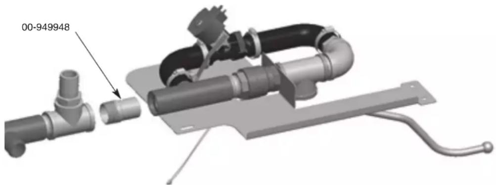
Fig. 14
- Remove drain cap, clamp, and rubber hose connected to drain tee located at load end of the unit.
- Swap flanged load end drain tee with the non-flange drain tee located under the wash section.
For a R-L machine (steps 9-11):
- Remove pipe (00-948761-00018) connecting the master drain and the nearest drain tee. 00-948761-00018 can be discarded. See Fig. 15.
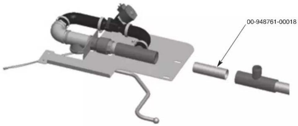
Fig. 15
- Remove rubber hose connected to drain tee located at load end of the unit.
- Swap load end drain tee including drain cap and clamp with the non-flange drain tee located at the unload end.
- Remove two bolts and associated hardware that secures the solenoid valve to the bracket. Retain these brackets and all hardware for use on load end platform.
- Loosen the clamps securing the two rubber hoses to the plastic drain tee and barbed fitting and remove hoses.
- Unplug drain interlock switch from terminal block 8TB-10 and 8TB-11 in the control box.
- Remove drain assembly from platform by unthreading the brass tee from the pipe nipple that connects the brass tee to the manual valve.
- Remove drain interlock switch bracket located on the underside of the platform and the bracket that secured the drain solenoid valve. Retain these brackets and all hardware for use on load end platform.
- Discard unload platform.
- Attach magnet and magnet retainer with hardware, removed in step 2, to the load end master drain handle weldment shipped with the machine. Ensure white dot on magnet faces down. See Fig. 16.
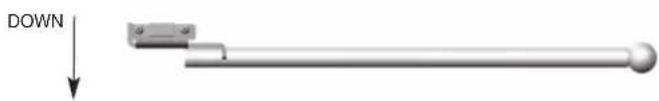
natural_image
Pure mechanical lever diagram without any text, numbers, or symbolsFig. 16
-
Attach drain interlock switch bracket, removed in step 16, to the underside of the load end master drain assembly platform shipped with the machine.
-
Assemble master drain plumbing, removed in step 15, to the load end platform. Ensure the brass elbow points towards rear of unit.
-
Loosen clamps securing rubber hoses to drain solenoid valve and rotate solenoid valve 180 degrees. Retighten clamps.
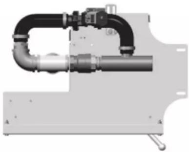
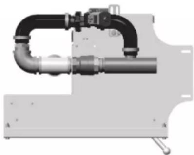
- Attach rubber hoses to plastic drain tee and barbed fitting assembly and tighten clamps. Ensure assembly matches correct diagram for direction of unit (Fig. 17) and that the solenoid valve is installed correctly for direction of drain water flow.
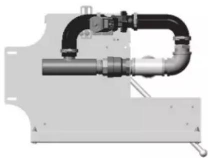
natural_image
Mechanical pipe assembly with black and gray components, no visible text or symbolsR - L
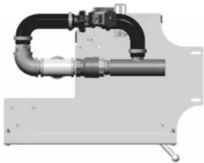
natural_image
Mechanical pipe fitting with black and metallic components (no visible text or symbols)L
Fig. 17
- Attach drain solenoid valve bracket, removed in step 16, to the platform and solenoid valve.
- Remove two bolts, nuts, and washers attached to front of the load platform.
- Insert drain pipe shipped with the machine (00-948761-00007) into the plastic drain tee on the master drain assembly.
- Attach master drain assembly and platform to the load end of the machine by sliding platform into the load end so that the drain pipe slips into the plastic drain tee. Ensure that the platform rests on top of the frame channel below the tee and that the front edge of the platform hooks over top of the front rail support. Reattach the two bolts, washers, and nuts to front of the platform removed in step 24.
- Secure platform to frame channels with hardware removed in step 4.
- Attach drain handle weldment to bottom of master drain assembly with the nut removed in step 2. Ensure that the handle sits above the drain handle support bracket.
- Remove two bolts, nuts, and washers attached to the load support bracket shipped with the machine (00-950109). See Fig. 18.
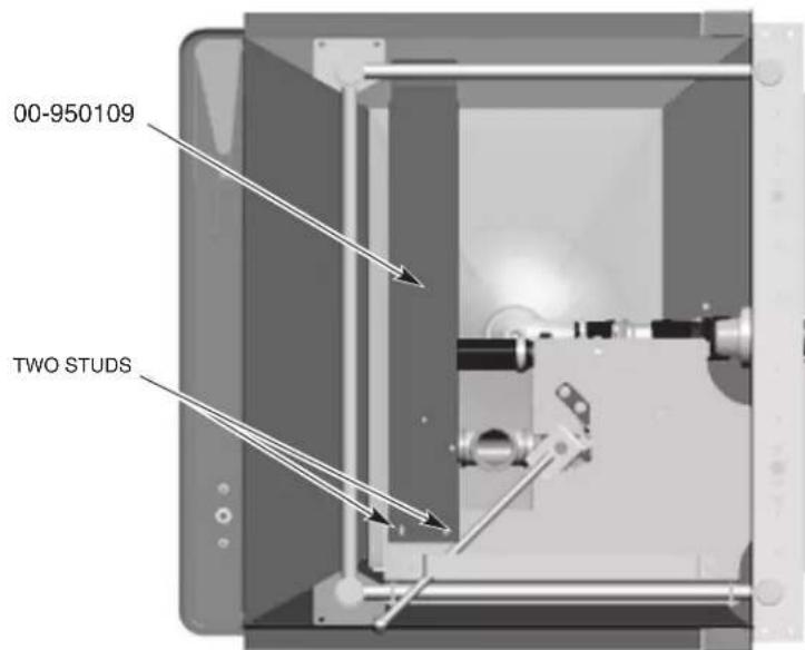
Bottom View (R-L Machine)
Fig. 18
- Attach load support bracket to load master drain platform using two studs located on the bottom of the load drain platform. Ensure bracket wraps over the top of the back rail support.
- Reattach the two bolts, washers, and nuts to the bracket removed in step 29.
- Reroute the drain solenoid valve cable from the unload end to the load end. Connect the D.I.N. connector to the drain solenoid.
- Connect new interlock switch cable shipped with the machine (949844-40) into terminal block 8TB-10 and 8TB-11 in the control box. Route cable to load end and plug into drain interlock switch using supplied electric connectors.
- Ensure that the master drain manual valve handle and interlock switch opens and closes properly.
- Apply the Master Drain label to the lower panel located above the Master Drain handle assembly.
Drain Back Pan Installation
Before installing the conveyor assembly, install the two drain back pans; one between the prewash and wash tank, and one between the dual rinse tank and the unload section.
Install the pan and saddle between the prewash and wash tank to the deflector located in the wash section ensuring that the pan slopes towards the prewash tank (Fig. 19). Secure the pan and saddle to the deflector using four 14 - 20 × 3/4 bolts and elastic stop nuts. The pins on the bottom of the pan should rest on the top edge of the lower track (Fig. 20).
NOTE: To install the pan and saddle to the deflector, unbolt the deflector from the track to allow clearance for saddle installation.
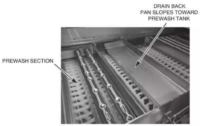
Fig. 19
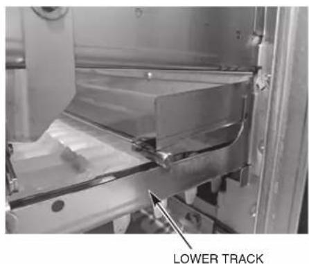
Fig. 20
Install the pan between the dual rinse and unload section ensuring that the pan slopes towards the dual rinse tank (Fig. 21). Secure the pan to the lower front and rear tracks using two 14 - 20 × 5/8" bolts and elastic stop nuts. The pins on the bottom of the pan should rest on the top edge of the lower track (Fig. 22).
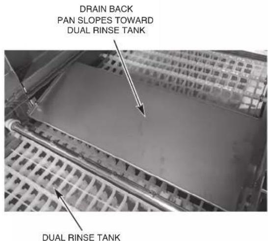
Fig. 21
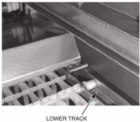
Fig. 22
Blower Dryer Assembly
NOTICE When installing the blower dryer fan assembly, do not stand, sit or lean on top of the air deflector or the air deflector supports as blower dryer performance could be compromised.
- Remove the blower dryer cover panels; front, rear, and top (Fig. 23).
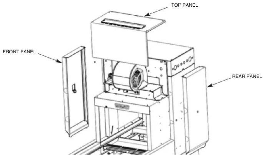
Fig. 23
- Install the blower assembly on top of the heater housing by lowering the blower assembly on an angle so that the front tabs hook underneath the notches on the top plate of the heater housing (Fig. 24 and 25).
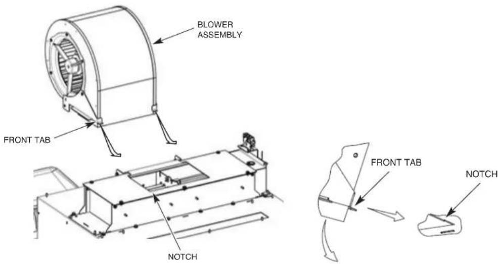
Fig. 24 Fig. 25
-
Lower the back side of the blower assembly down so that the holes in the blower mounting brackets line up with the holes in the support brackets on the heater housing (Fig. 26).
-
Install 14 -20 hex head cap screws with washers and stop nuts as shown in Fig. 26 and tighten.
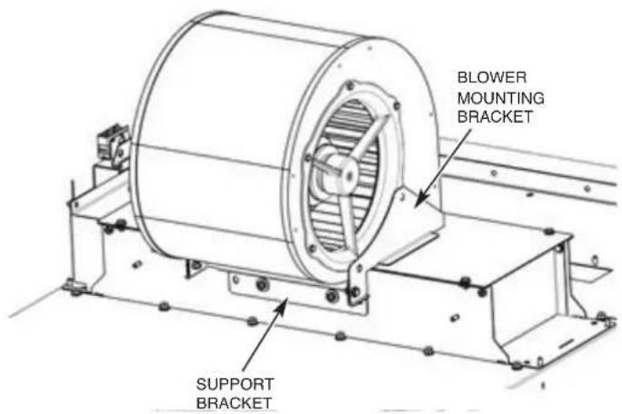
Fig. 26
- Route blower cable through strain relief located on the vertical enclosure panel and through strain relief located at rear of control box.
NOTE: Ensure that the cable is not routed on the side of the blower where the air intake chamber openings are located.
- Connect blower motor wires to 9TB terminal block in the control box. If wires are stripped, cut end of wire to remove stripped end before making connection. Ensure motor is wired per machine voltage (see data plate for machine voltage) (Fig. 27).
NOTE: The white wires are not used. Cut the white wires back at the sheath.
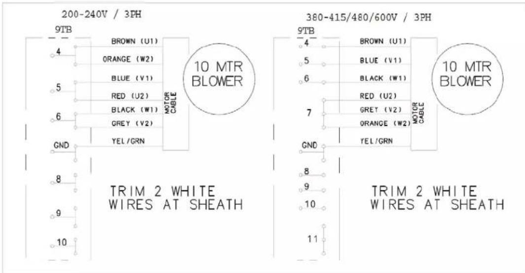
Fig. 27
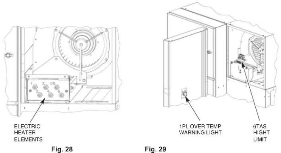
NOTE: If the blower dryer is equipped with electric heaters, connect electric heater wires marked 7HTR-1, -2, -3, -4, -5 and -6 to the heating elements in the blower dryer (Fig. 28). Also connect the electric heater high limit over temp wires marked 6TAS-C, -NC, & -NO and the over temp warning light wires marked 1PL-X1 & -X2 to the designated terminals located on 6TAS high limit switch mounted to the electric heater element cover plate (Fig. 29) and 1PL over temp warning light mounted on the front blower dryer cover panel (Fig 29).
Advansys Module Installation
Refer to Hobart Service FT1000e Advansys Installation Manual, F-45777.
Control Box Connections
Refer to the electrical diagram stored inside the main control box door. After use, make sure that the diagram is placed inside the control box.
Although each section is prewired, components in the load and unload sections must be electrically connected to the main control box that is attached to the unload section. All wires that need to be connected are furnished with stripped leads and have crimped barrel terminal for terminal block connections. Also provided are locking plug connectors for control boards.
Run wires in proper routing clips, channels and so forth to openings in the lower rear of the main control box. Run wires (in conduit) through conduit ttings; run cordage through strain reliefs. Make proper connections for wires and cordage. Properly tighten strain reliefs and conduit ttings.
After all wires are routed and connected at terminal block, check to make sure any unused holes in the lower rear portion of the control box are plugged.
DO NOT permit electric cables or conduit to touch steam pipes.
When making connections to the terminal block (8TB), insert the wire into the designated terminal opening. Using a small screwdriver, pry the corresponding tab down to make connection and secure wire. DO NOT STRIP WIRES.
Using the supplied NSF-approved sealer, apply a bead of caulk where each side of the control box meets the tank support rails to allow any moisture condensation to drain back into the tank.
Electric Booster Heater Wiring
If machine is equipped with an electric booster heater, connect the electric heater wires marked 6HTR-1, -2, -3, -4, -5 and -6 to the heating elements located in the electric booster enclosure (Fig. 30)
NOTE: While holding the back nut behind the wire terminal, torque the outer nut to 16-18 inch pounds,
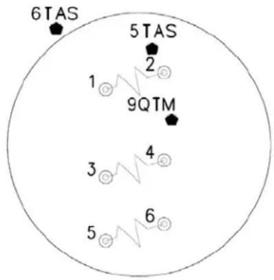
Fig. 30
Door and Drain Interlock Switches (Prewash to Wash Tank)
For L-R machines, route the 4-wire cable from the prewash tank float box into the wash tank float box and tighten the strain relief.
- Remove the red wire from the wire connector which also contains the blue wire labeled DOOR and connect this red wire to the blue wire labeled LS-RED.
- Connect the blue wire labeled DOOR to the second blue wire labeled DOOR from the prewash tank.
- Remove the red wire from the wire connector which also contains the blue wire labeled DRAIN and connect this red wire to the blue wire labeled DS-RED.
- Connect the blue wire labeled DRAIN to the second blue wire labeled DRAIN from the prewash tank.
For R-L machines, route the 4-wire cable from the wash tank float box into the prewash tank float box and tighten the strain relief.
- Connect the blue wire labeled LS-BLACK to the black wire from the wash tank door reed switch cable (cable thru upper strain relief).
- Connect the blue wired labeled DOOR to the red wire from the wash tank door reed switch cable (cable thru upper strain relief).
- Connect the blue wire labeled DS-BLACK to the black wire from the wash tank drain reed switch cable (cable thru middle strain relief).
- Connect the blue wire labeled DRAIN to the red wire from the wash tank drain reed switch cable (cable thru middle strain relief).
NOTE: Two extra wire connectors are provided in the parts installation box.
Check all factory water lines, particularly unions. Tighten if necessary.
Water Supply
The water supply must be within the recommended hardness range of 3 grains or less per gallon. Higher hardness may cause excessive formation of lime scale. Chlorides must not exceed 50 ppm.
WATER PRESSURE REQUIREMENTS (FLOWING) – PSIG
| Hot Water Cold | Water | |
| FT1000e/FT1000Se 30-35 --- | ||
| FT1000e/FT1000Se with Auto Clean 40-45 --- | ||
| FT1000e-EGR/ FT1000Se-EGR 30-35 30-35 | ||
| FT1000e-EGR/ FT1000Se-EGR with Auto Clean | 40-45 | 30-35 |
| FT1000e-ADV | 40-45 | 30-35 |
If the water pressure is higher than these requirements, a pressure regulating valve with internal thermal expansion bypass must be supplied and installed (by others) in the water supply line to the dishwasher.
NOTICE The water pressure regulator must have a relief bypass. Failure to use the proper type of pressure regulator may result in damage to the unit.
A water hammer arrestor meeting ASSE-1010 standard or equivalent should be supplied and installed (by others) in the hot and cold (if applicable) water supply lines at the service connections.
Fill
All machines have a single 1" NPT female common connection point for the fill. The minimum water temperature for this connection is 110^ F.
Final Rinse
For FT1000e Base models, the required minimum hot water temperature for the final rinse is 110^ F when an electric or steam booster heater is supplied (same connection point for fill). For FT1000e Energy Recovery and Advansys models, the minimum cold water temperature for the final rinse is 55^ F when an electric or steam booster heater is supplied. The Energy Recovery and Advansys models have a single 1" NPT female cold water connection point.
NOTICE Remove the final rinse arms and purge the final rinse system prior to operation. This will reduce the possibility of clogging the final rinse nozzles. To properly purge the unit, activate the final rinse for 3 to 5 minutes and then reinstall the rinse arms.
Drain
For machines without Auto Clean or Auto Delime, connect the drain at the 2" NPT threaded fitting located at either the load end or the unload end of the machine.
NOTE: The plug fitting and the threaded drain fitting can be interchanged to reverse the drain end of the machine.
On machines equipped with Auto Clean and/or Auto Delime, the master drain assembly is located at the unload end of the machine. Connect the drain at the 2" NPT threaded fitting. See RELOCATING MASTER DRAIN TO LOAD END (page 16) if machine drain is to be located at load end.
NOTE: On machines equipped with Auto Clean and without the ASR section, the master drain assembly cannot be relocated to the load end of the machine.
If a grease trap is required by code, the drain should have a flow rate of 38 gallons per minute.
Line Strainers
Line strainers on the machine should be cleaned after installation and within the first week of operation. The line strainers will collect oils and other contaminants. Clogged line strainers will cause restrictions to the flow of water or steam and will reduce overall performance of the machine.
Steam Supply (When Equipped)
Check all factory steam lines for leaks, particularly unions. Tighten if necessary.
The steam supply must be 12-45 psig flowing pressure at the dishwasher. Machines have a single 1 12 NPT female fitting for connection underneath the unload end.
NOTE: If available steam pressure is less than 12 psi flowing at the machine, contact Hobart Warewash Sales Engineering.
| STEAM USAGE / REQUIREMENTS – POUNDS PER HOUR | |||||
| Model | Tank Heat | Booster110 F IncomingWater, 75 F Rise | Dryer | TOTALTank Heat & Booster | TOTALTank Heat, Booster, & Dryer |
| FT1000e-BAS 215 64 - 279 - | |||||
| FT1000Se-BAS 194 64 - 258 - | |||||
| FT1000e-BAS-BD 215 64 | 52 279 331 | ||||
| FT1000Se-BAS-BD | 194 64 | 52 258 310 | |||
| FT1000e-EGR | 215 64 | -279 - | |||
| FT1000Se-EGR | 194 64 | -258 - | |||
| FT1000e-EGR-BD | 215 64 | 52 279 331 | |||
| FT1000Se-EGR-BD | 194 64 | 52 258 310 | |||
| FT1000e-ADV | 138 | - | -138 | - | |
Steam Tank Heaters – Condensate Return Lines
The wash tank, power rinse tank, and dual rinse tank may be equipped with steam coil tank heaters. If steam coils are used, a condensate return, gravity type, must be connected for each coil. Bucket-type traps are furnished. The connection points for the condensate return lines for all three coils are 34 " NPT female pipe fittings. Condensate lines must not be plumbed uphill.
Steam Booster Heater – Condensate Return Line & Relief Valves
The connection point for the condensate return line for the steam booster heater is a 34 " NPT female pipe fitting. Bucket type trap is furnished. Condensate lines must not be plumbed uphill. The steam booster heater is equipped with a steam relief valve that has a 1" NPT female pipe fitting that must be piped to an open drain receiver in the floor. The steam booster heater is also equipped with a hot water relief valve that has a 34 " NPT female pipe fitting that must be piped to an open drain receiver in the floor.
The steam booster thermostat (bulb and capillary tube style) is mounted and wired in the main control box. The bulb and capillary tube is shipped with the control box on the center section. During installation, the bulb and capillary tube must be carefully uncoiled and routed to the steam booster and inserted in the booster outlet hot water line through the supplied fitting. Insert the bulb two-thirds of the way into the booster body (refer to tag attached to thermostat, F-44107).
Steam Blower Dryer (When Equipped) – Condensate Return Line
NOTE: The steam blower dryer is equipped with a steam on/off valve. The steam supply is ON when the machine is ON and OFF when the machine is OFF.
The steam blower dryer has a condensate return, gravity type; bucket type trap furnished. The connection point for the condensate return line for the coil is a 34 " NPT female pipe fitting. Condensate lines must not be plumbed uphill.
Fill & Auto Clean (When Equipped) Hose Connections
Route Fill & Auto Clean hoses from solenoid valves, located under the unload section, to appropriate tank connection fittings. See below diagrams for solenoid valve to tank designations (Fig 31 & 32).
Cold Water - Braided Stainless Steel Hose Connections
- Final rinse pump outlet to top of energy recovery coil.
- Bottom of energy recovery coil to plumbing connection at bottom of booster.
- Top plumbing connection of booster to final rinse plumbing assembly.
Hot Water - Braided Stainless Steel Hose Connections
- Autoclean master valve outlet to vacuum breaker inlet.
-
Vacuum breaker outlet to autoclean manifold.
-
Prewash hot water fill valve to prewash fill air gap box.
- Power rinse hot water fill valve to power rinse fill air gap box.
A. For FT1000Se models, wash hot water fill valve to wash fill air gap box.
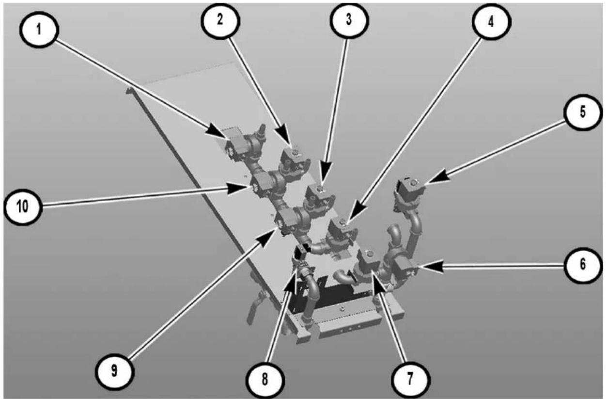
Fig. 31
| Right to Left Solenoid Valve Layout | ||
| Number Description | Solenoid Valve | |
| 1 Autoclean | ASR valve 9 SOL | |
| 2 Autoclean | Prewash / Wash Lower Nozzles valve 10 SOL | |
| 3 Autoclean | Wash Upper Nozzles valve 12 SOL | |
| 4 Autoclean | Dual Rinse valve 14 SOL | |
| 5 Autoclean | Master Valve 15 SOL | |
| 6 Power Rinse | Hot Water Fill Valve 1 SOL | |
| 7 | Prewash Hot Water Fill Valve | 3 SOL for FT10002 SOL for FT1000S |
| 8 Cold Water | Fill Valve 5 SOL | |
| 9 Autoclean | Power Rinse valve 13 SOL | |
| 10 Autoclean | Prewash Upper Nozzles valve 11 SOL | |
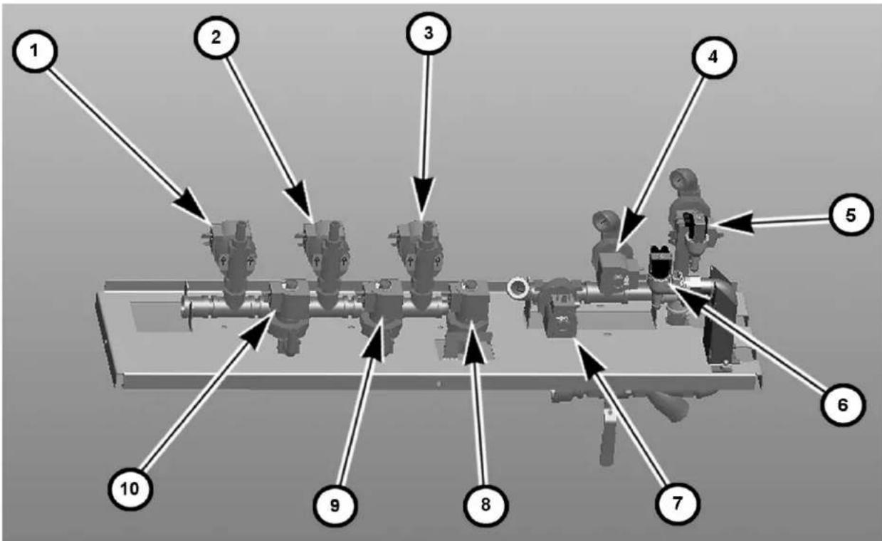
Fig. 32
| Left to Right Solenoid Valve Layout | ||
| Number Description | Solenoid Valve | |
| 1 Autoclean | ASR valve 9 SOL | |
| 2 Autoclean | Prewash Upper Nozzles valve 11 SOL | |
| 3 Autoclean | Power Rinse valve 13 SOL | |
| 4 Power Rinse | Hot Water Fill Valve 1 SOL | |
| 5 Autoclean | Master Valve 15 SOL | |
| 6 Cold Water | Fill Valve 5 SOL | |
| 7 | Prewash Hot Water Fill Valve | 3 SOL for FT10002 SOL for FT1000S |
| 8 Autoclean | Dual Rinse 14 SOL | |
| 9 Autoclean | Wash Upper Nozzles valve 12 SOL | |
| 10 Autoclean | Prewash / Wash Lower Nozzles valve 10 SOL | |
NOTE: For FT1000e and FT1000Se (Non-Advansys), Autoclean master valve will become hot water fill for pumped rinse, on both directions.
⚠ WARNING Electrical and grounding connections must comply with applicable portions of the National Electrical Code (NFPA No. 70, latest edition) and/or other local electrical codes.
⚠ WARNING Disconnect the electrical power to the machine and follow lockout/tagout procedures. There may be multiple circuits. Be sure all circuits are disconnected.
With power to all service connections locked out/tagged out, verify that the line and load service connections have been properly tightened.
Refer to the electrical diagram located inside the control box door. Some machines may require more than one electrical power supply connection. All electrical supply lines to the machine must be disconnected when servicing machine.
Run electrical conduit(s) thru provided openings on the back side of the machine behind the control box. Install conduit fitting(s) at knockouts on rear of control box (Fig. 33).
FEED CONDUIT(S) ACROSS OPENING BEHIND CONTROL BOX AND TERMINATE AT KNOCKOUTS LOCATED AT REAR OF CONTROL BOX WITH PROPER CONDUIT FITTING(S)
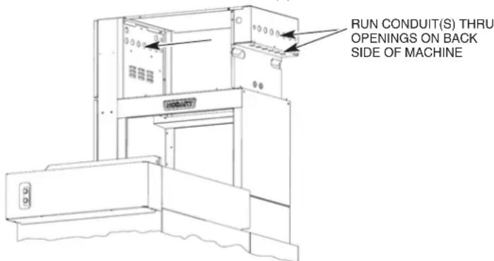
Fig. 33
Motor Overloads
Ensure all motor overloads in control panel are not tripped by pressing in on the blue reset button located on the front of each motor overload (Fig 34). Verify all overloads are set to the proper amp rating per the chart located on the wiring diagram and adjust as required.
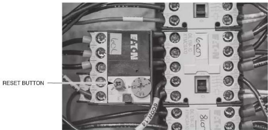
Fig. 34
Checking Motor Rotation (Three-Phase Motors)
Pumps, conveyor motor, exhaust fan and blower dryer fan motors (when equipped) are all three-phase motors. Before placing machine into service, check to verify correct rotation by observing motor direction.
If any pump motor does not rotate in the correct direction, check the rotation of the other motors. If they all are rotating backward, disconnect the electrical supply and interchange any two of the incoming power supply leads. If all motors are not running in the correct direction, only change the two incoming wires of the motor(s) that is running backward. Reconnect electrical power, push the START switch and verify that the motors rotate in the proper direction.
NOTE: If the conveyor motor does not rotate in the correct direction, disconnect the electrical power supply and interchange any two of the conveyor motor wires from the Frequency Inverter at terminal 8TB-1, -2, or -3.
Separate Electrical Connections
Separate electrical connections in the main control box may be required for an optional electric blower dryer heater (when equipped) and for optional electric tank heaters (when equipped) unless equipped with optional circuit breakers. When equipped with an optional electric booster heater, a separate electrical connection at the booster is always required.
Voltage Adjustment
This adjustment procedure applies to all FT1000e dishwashers equipped with steam heat and rated at 200 to 240 volts, 50/60 Hz, 3 phase. All other FT1000e dishwasher voltages are preset at the factory and do not require this adjustment procedure.
THIS PROCEDURE MUST BE DONE ONLY BY A QUALIFIED HOBART-TRAINED SERVICE TECHNICIAN.
If the supply voltage to the machine is 224 to 264 volts, no change is necessary. The control circuit transformer [1T] should already be set to operate at 240 volts.
If the supply voltage to the machine is 177 to 224 volts, the control circuit transformer [1T] must be changed to operate at 208 volts.
Electrical Connection - Detergent & Rinse Aid Dispensers
NOTE: This machine must be operated with an automatic detergent feeder, including a visual means to verify that detergents are delivered or a visual or audible alarm to signal if detergents are not available for delivery to the washing system. Please see instructions for electrical and plumbing connections located in this manual and in the feeder equipment manual. Chemical feeders are supplied and installed by others.
The machine electrical supply voltage can be used to supply electrical power source for a detergent dispenser and/or a rinse aid dispenser-up to 1.5 amperes each.
Terminal connections, DPS1 and DPS2, are provided for a detergent dispenser (ON when the pumps are running). Terminal connections, RPS1 and RPS2, are provided for a rinse aid dispenser (ON when the final rinse is on). A location for 12 " conduit is provided at the rear of the control panel for connection of these devices.
A plugged hole is provided in the wash tank on the left side towards the front lower corner for a detergent sensor probe. A plugged hole is provided at the rear of the wash chamber for a liquid detergent dispenser inlet. A 1/8" NPT plug is provided at the rear side of the holding tank located under the unload end of the machine for a rinse aid inlet (Fig. 35). The preferred location for a detergent dispenser and/or rinse aid dispenser is at the top of the machine. Two stainless steel brackets are provided for dispenser mounting (shipped loose, field install at preferred locations on top panels of unit). Route all plumbing and wiring between the rear access panels and chamber where possible.
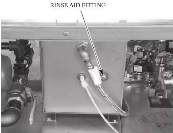
Fig. 35
External Vent Fan Control
The vent fan control circuit can be used to switch the facility's exhaust vent fan on and off with the dish machine. The vent fan is ON when the main power switch on the dish machine is turned on and the vent fan is OFF when the main power switch on the dish machine is turned off. The vent fan control connection points are labeled VF1 and VF2 and are located on 9TB terminal block in the upper control box behind the stainless-steel protective cover. A 12 conduit hole is provided at the rear of the control panel for the vent fan control conduit connection.
The vent fan control circuit is a switching circuit. Power for the circuit is supplied from the facility's control power to the exhaust fan on the roof.
Maximum pilot duty load for the VFC switch connection is 1.5 amps.
CONVEYOR ASSEMBLY
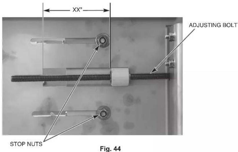
Prior to installing the conveyor, loosen the two stop nuts located on both the front and rear take-up assemblies on the outside of the tracks located at the load end of the machine. Thread the adjusting bolts out as far as possible moving the front and rear conveyor guides towards the machine entrance (Fig. 36).
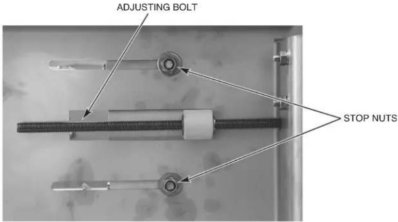
Fig. 36
Remove the conveyor drive chain from the conveyor gear motor.
Loading and Joining the Conveyor Sections
- All conveyor sections are numbered: ROLL 1, ROLL 2, ROLL 3, ROLL 4, etc.; install them in numerical sequence.
- Remove 3" tall track extensions from load end (front & rear) by removing two sets of hardware to install conveyor. Re-assemble track extensions after conveyor is assembled.
- Raise the loading platform and place a piece of cardboard under, around and above the platform to protect it from being scratched during conveyor installation.
- Remove the chain cover on the unload end and then remove the drive chain from the conveyor gear motor so that the conveyor sprockets are free to rotate.
- Position the first section of conveyor in line with the machine at the load end. The flight links must lean towards the load end of the machine (Fig. 37).
- For welded security conveyor assemblies, ensure the retaining rings are tack welded to the conveyor rods.

Fig. 37
- Tie a rope to the first conveyor rod. Feed the rope through the machine following the desired path of the conveyor with the flight links pointing up. The conveyor rollers must be fed between the upper roller guide and the track (Fig. 38).
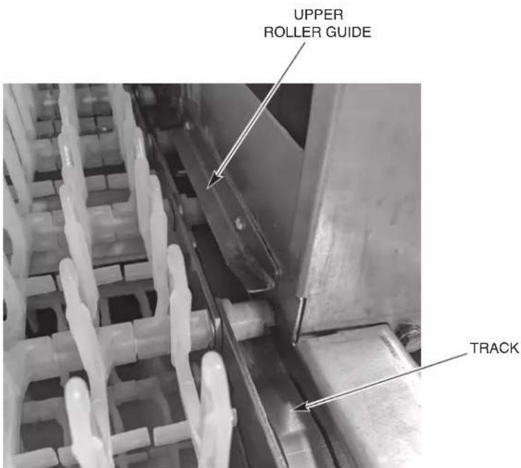
Fig. 38
- Remove the conveyor roller from one end of the last conveyor rod on the first section. Then pull the conveyor rod out and save the roller and washers for re-assembly. To join the sections, thread the rod back through the side bars and washer and then through the flight links, alternating the links from the first and second sections, and then through the washer and side bars on the opposite side. Complete the assembly by attaching the conveyor roller with a new retaining ring (Figs. 39 & 40). Spin the roller to ensure that the retaining ring has been secured to the conveyor rod. Always use a new retaining ring to secure a tight grip on the conveyor rod. Repeat this step for joining each succeeding conveyor section.
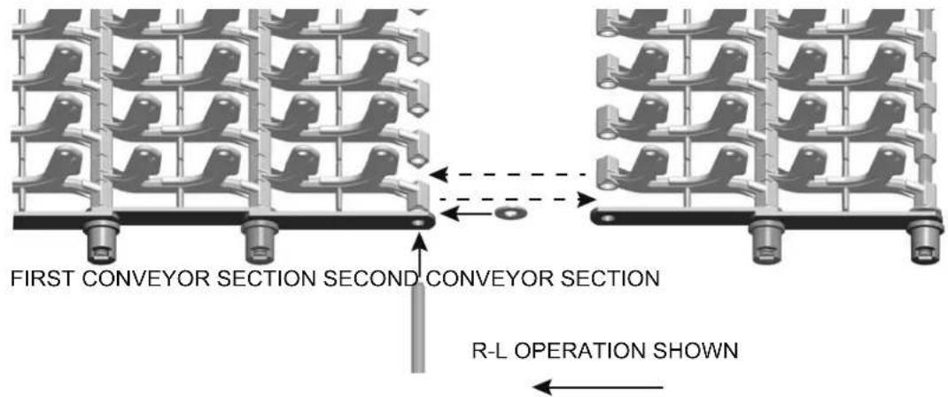
Fig. 39
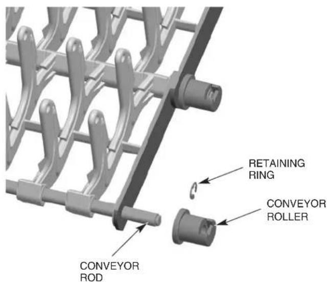
Fig. 40
Pull the conveyor through the machine starting at the load end, around the conveyor sprockets at the unload end, down to the top of the lower track and back through the machine. Make sure conveyor rollers do not feed under tracks.
Join the ends of the conveyor by threading the final conveyor rod through both rows of flight links and the side bars on both sides. Conveyor links alternate with both ends of the link on the inside following by both ends of the next link on the outside, except for the conveyor offset link, which is only used on the standard conveyor.
Conveyor Offset Side Bar
Conveyor offset side bars are supplied for use with the standard conveyors and are to be used, if necessary, when making the final connection to join the two conveyor ends. The total length of all conveyor sections shipped may slightly exceed the optimal length required for the machine's length and conveyor's travel. This can possibly require one or two rows of flight links to be removed together with all associated rods, side bars and end rollers. When the proper length of conveyor has been determined, pull the ends of the last two sections together to examine the side bar patterns. If both sections end with the side bars on the outside position or both sections end with the side bars on the inside position (Fig. 41), you must replace the last side bars on one of the sections with the offset side bars to maintain the pattern (Fig. 42). However, if the sections end such that the inside to outside pattern of the side bars will be maintained, they can be joined without the use of the offset side bars (Fig. 43). Complete the joining of the conveyor sections as necessary to maintain the side bar pattern.
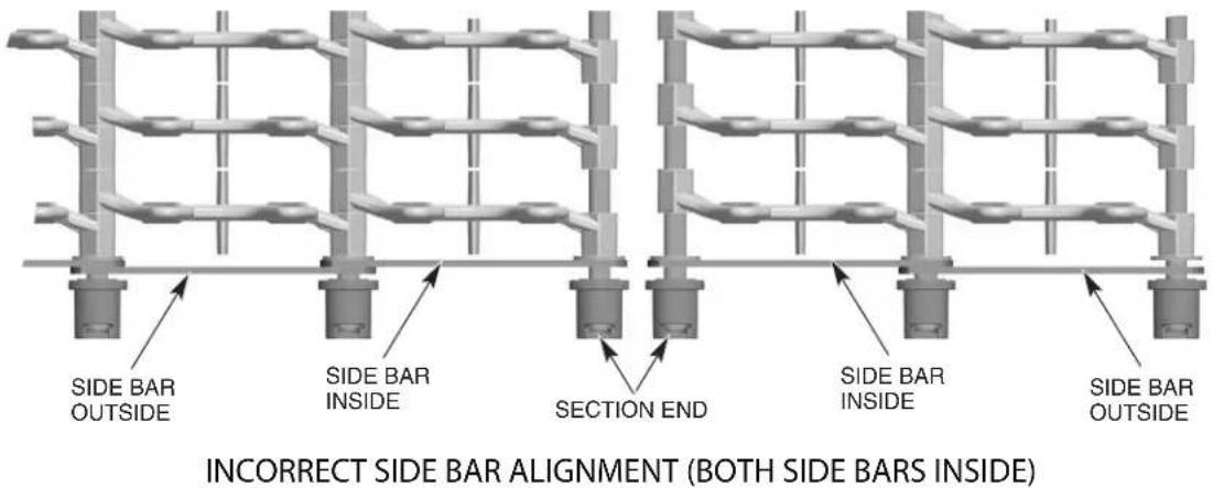
Fig. 41
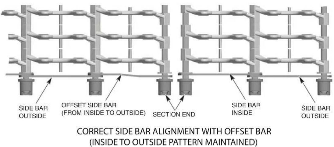
Fig. 42

CORRECT SIDE BAR ALIGNMENT WITHOUT OFFSET LINK (INSIDE TO OUTSIDE PATTERN MAINTAINED)
Fig. 43
NOTE: The proper length of conveyor, when adjusted, will have the flight links close to (within 1") or engaging the load fingers at the load platform. It may be necessary to remove one or two conveyor rods (with rows of flight links) to obtain the desired length.
NOTE: Each time a conveyor roller is installed or replaced, a NEW retaining ring (Fig. 40) must be used.
Once the conveyor is installed, reinstall the conveyor drive chain to the conveyor gear motor.
Adjusting the Conveyor Take-Up Unit (Load Section)
Tighten the tension on the conveyor by turning the adjusting bolts on the take-up units until the conveyor is no longer sagging at either the load or unload end and then re-tighten the two stop nuts located on both the front and rear take-up assemblies on the outside of the tracks (Fig. 44).
NOTE: When conveyor is adjusted to proper tension, ensure adjusting bolts are adjusted evenly on the front and rear sides by measuring from the edge of the track cutout to the face of the roller guide (Fig. 44).
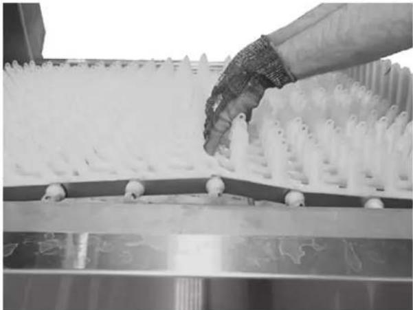
Run the conveyor for 20 minutes. During this time, it may be convenient to perform the booster thermostat calibration described under "Calibrating the Booster Thermostat" in the Miscellaneous section of this manual. After running the conveyor for 20 minutes, stop the conveyor and check the tension. Proper tension is achieved when you grab both sides of the conveyor in the middle of the unload and lift so the bottom of the rollers of the conveyor (both sides) just clear the top surface of the unload tracks (Fig. 45).
natural_image
Close-up of a hand handling white plastic spray particles on a conveyor belt (no text or symbols visible)Fig. 45
FT1000e Conveyor Jam Switch Setting Verification/Adjustment
NOTE: This procedure should be performed after the machine is fully installed and operational with no ware on conveyor and will require a torque wrench capable of 150 foot pounds.
- Remove unload lower trim panel on conveyor drive side of machine to access conveyor drive assembly. (Front panel on L-R machines, rear panel on R-L machines.)
- Start the machine and allow the conveyor to run.
- Using a 12 " drive torque wrench set to 75 foot pounds with a 5/8" socket, apply torque in a clockwise direction to the hex rod protruding from the base of the drive assembly (Fig. 46).
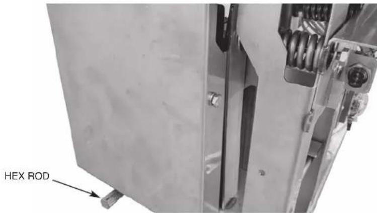
Fig. 46
a. If conveyor jam switch shuts machine off when torqued to 70-80 foot pounds, no further action is required. Replace lower trim panel.
b. If the conveyor jam switch does not shut the machine off when torqued to 70-80 foot pounds, proceed to step 4.
- Remove unload end panel and verify the two springs are assembled correctly and compressed to the correct dimension as shown below in Fig 47.
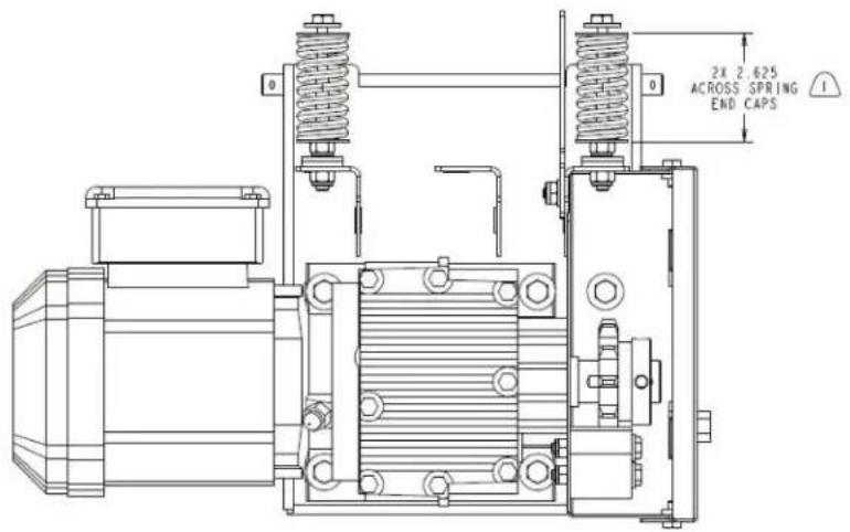
THIS DIMENSION IS PRIOR TO ASSEMBLY OF THE DRIVE CHAIN. AFTER ASSEMBLY OF THE DRIVE CHAIN THIS DIMENSION WILL DECREASE TO 2.375±.125.
Fig. 47
a. If any of the springs are not compressed to the correct dimension, adjust the compression as necessary by loosening or tightening the nut adjacent to the spring.
- Verify position of conveyor anti-jam actuator plate and jam sensor to ensure they are positioned as shown below and adjust as necessary (Figs 48 and 49).
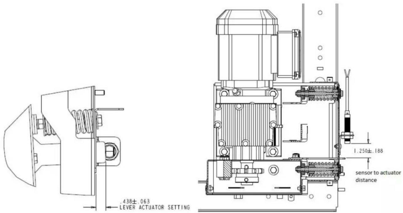
Fig. 48 Fig. 49
- Refer to steps 2 and 3 and re-check the conveyor jam switch operation.
- Re-install lower trim panels.
MISCELLANEOUS
Vent
NOTICE Do not step on top chamber covers when installing vent.
Vent connection must fit inside 16" diameter vent stack, providing 750 CFM exhaust at machine connection (at standard air conditions).
NOTE: Ensure exhaust condensate pan is not blocking air intake.
For all models equipped with energy recovery, a backdraft preventer is required at building penetration to prevent energy recovery coil from freezing (supplied and installed by others).
The air baffles are factory set. After machine is placed in full operation with customer running ware, if adjustments are required, refer to the service manual or contact your local Hobart Service office.
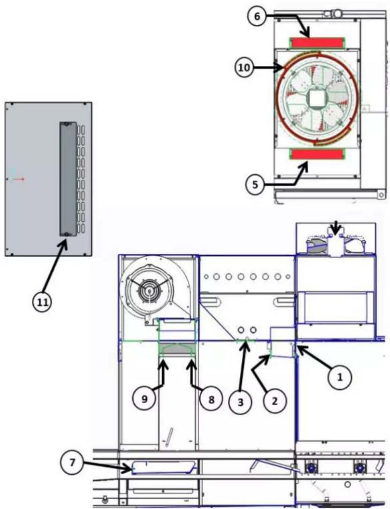
Air Baffle Settings
The following diagrams and charts outline the standard factory baffle settings for each of the machine configurations.
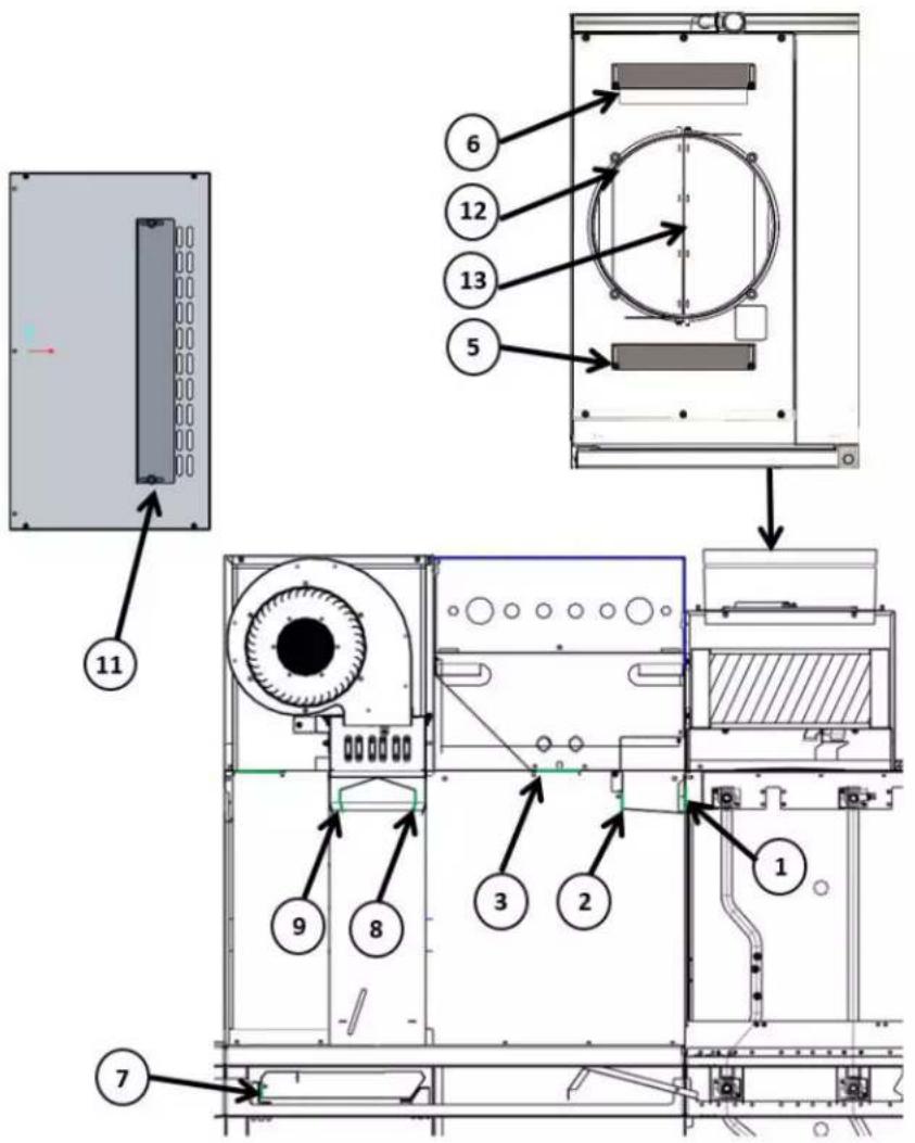
| FT1000e & FT1000Se WITHOUT BLOWER DRYER | |
| Baffle Number Baffle Setting (Open) | |
| 1 100% | |
| 2 50% (5/8") | |
| 3 N/A | |
| 4 N/A | |
| 5 Closed | |
| 6 Closed | |
| 7 N/A | |
| 8 (entrance) N/A | |
| 9 (exit) N/A | |
| 10 N/A | |
| 11 N/A | |
| 12 45° Open | |
| 13 45° Open | |
| FT1000e & FT1000Se WITH BLOWER DRYER | |
| Baffle Number Baffle Setting (Open) | |
| 1 100% | |
| 2 50% (5/8") | |
| 3 Closed | |
| 4 N/A | |
| 5 Closed | |
| 6 Closed | |
| 7 Closed | |
| 8 (entrance) | 12° Towards Unload |
| 9 (exit) 0° (Vertical) | |
| 10 N/A | |
| 11 2 Rows Open | |
| 12 45° Open | |
| 13 45° Open | |
FT1000e Advansys
| FT1000e ADVANSYS WITH BLOWER DRYER | |
| Baffle Number Baffle Setting (Open) | |
| 1 100% | |
| 2 25% (3/8") | |
| 3 Closed | |
| 4 N/A | |
| 5 Closed | |
| 6 Closed | |
| 7 Closed | |
| 8 (entrance) 12° Towards Unload | |
| 9 (exit) 0° (Vertical) | |
| 10 #3 | |
| 11 2 Rows Open | |
| 12 N/A | |
| 13 N/A | |
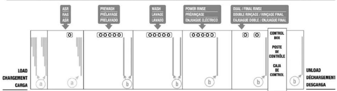
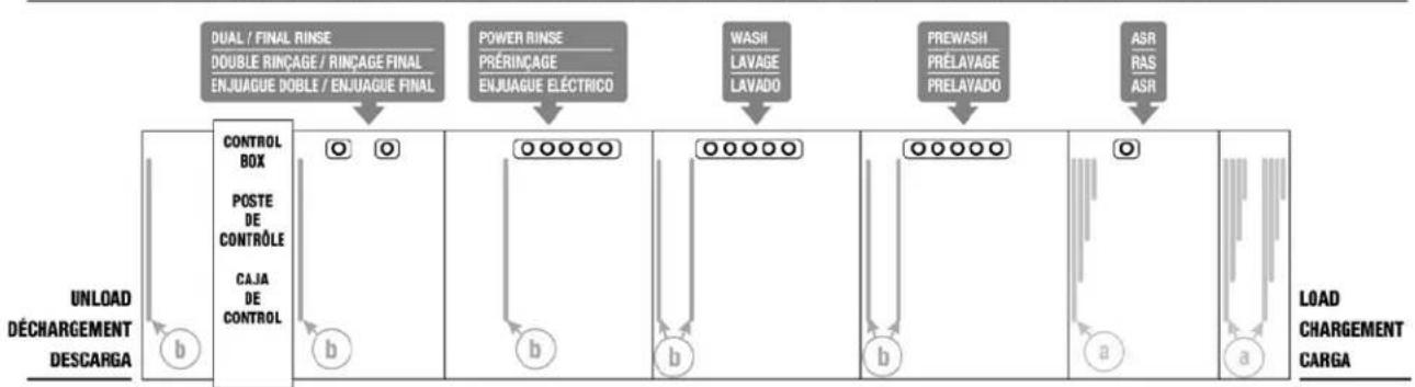
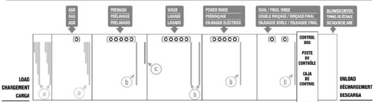
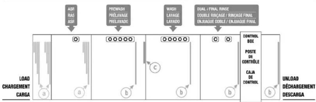
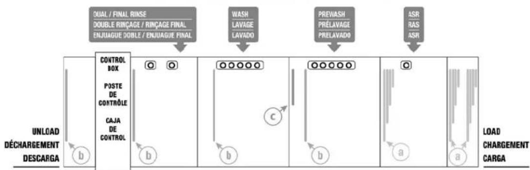
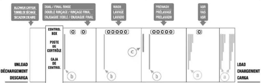
Curtain Configurations
FT1000e-BAS & FT1000e-EGR (Standard Height)
(machine may not be equipped with ASR module)
Left to Right
8' CENTER SECTION | ZONE CENTRALE DE 8 pi (2438 mm) | ZONA CENTRAL DE 8'
flowchart
graph LR
    A["ASR RAS ASR"] --> B["○"]
    C["PREWASH PRÉLAVAGE PRELAVADO"] --> D["○○○○○"]
    E["WASH LAVAGE LAVADO"] --> F["○○○○○"]
    G["POWER RINSE PRÉRINÇAGE ENJUAGUE ÉLECTRICO"] --> H["○○○○○"]
    I["DUAL / FINAL RINSE DOUBLE RINÇAGE / RINÇAGE FINAL ENJUAGUE DOBLE / ENJUAGUE FINAL"] --> J["○"]
    K["CONTROL BOX POSTE DE CONTRÔLE CAJA DE CONTROL"] --> L["○"]
    M["UNLOAD DÉCHARGEMENT DESCARGA"] --> N["○"]
    B --> O["a"]
    D --> P["b"]
    F --> Q["b"]
    J --> R["b"]
    L --> S["b"]
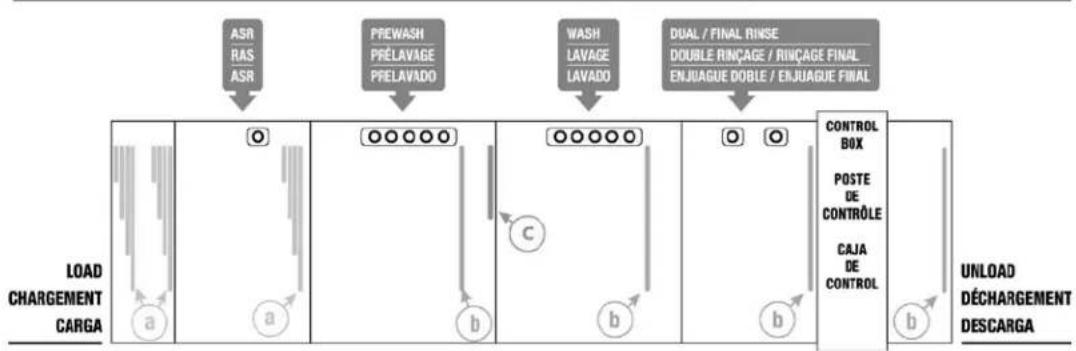
Right to Left
8' CENTER SECTION | ZONE CENTRALE DE 8 pi (2438 mm) | ZONA CENTRAL DE 8'
flowchart
graph LR
    A["UNLOAD DÉCHARGEMENT DESCARGA"] --> B["CONTROL BOX"]
    B --> C["POSTE DE CONTRÔLE"]
    C --> D["CAJA DE CONTROL"]
    D --> E["O O"]
    E --> F["POWER RINSE"]
    F --> G["DOUBLE RINÇAGE / RINÇAGE FINAL ENJUAGUE DOBLE / ENJUAGUE FINAL"]
    G --> H["WASII LAVAGE LAVADO"]
    H --> I["PREWASHI PRÉLAVAGE PRELAVADO"]
    I --> J["ASR RAS ASR"]
    J --> K["LOAD CHARGEMENT CARGA"]
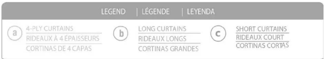
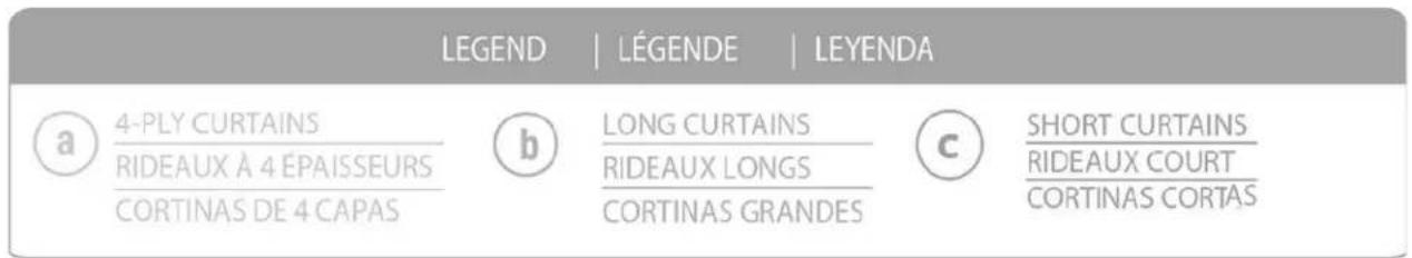
LEGEND | LÉGENDE | LEYENDA

4-PLY CURTAINS
(machine may not be equipped with ASR module)
Left to Right
5' CENTER SECTION I ZONE CENTRALE DE 5 pi (1524 mm) I ZONA CENTRAL DE 5'
flowchart
graph TD
    A["ASR / RAS / ASR"] --> B["PREWASH / PRÉLAVAGE / PRELAVADO"]
    B --> C["WASH / LAVAGE / LAVADO"]
    C --> D["DUAL / FINAL RINSE / DOUBLE RINÇAGE / RINÇAGE FINAL / ENJUAGUE DOBLE / ENJUAGUE FINAL"]
    D --> E["CONTROL BOX"]
    E --> F["POSTE DE CONTRÔLE"]
    F --> G["CAJA DE CONTROL"]
    G --> H["UNLOAD DÉCHARGEMENT DESCARGA"]
    subgraph Process Steps
        I["LOAD CHARGEMENT CARGA"] --> J["a"]
        J --> K["o"]
        K --> L["a"]
        L --> M["b"]
        M --> N["c"]
        N --> O["b"]
        O --> P["b"]
        P --> Q["o"]
        Q --> R["o"]
    end
Right to Left
5' CENTER SECTION | ZONE CENTRALE DE 5 pi (1524 mm) | ZONA CENTRAL DE 5'
flowchart
graph LR
    A["DUAL / FINAL RINSE\nDOUBLE RINÇAGE / RINÇAGE FINAL\nENJUAGUE DOBLE / ENJUAGUE FINAL"] --> B["CONTROL BOX"]
    B --> C["POSTE DE CONTRÔLE"]
    C --> D["CAJA DE CONTROL"]
    D --> E["UNLOAD DÉCHARGEMENT DESCARGA"]
    F["WASH LAVAGE LAVADO"] --> G["○○○○○"]
    H["PREWASII PRÉLAVAGE PRELAVADO"] --> I["○○○○○"]
    J["ASR RAS ASR"] --> K["○"]
    G --> L["Load CHARGEMENT CARGA"]
    I --> M["a"]
    K --> N["a"]
LEGEND | LÉGENDE | LEYENDA

4-PLY CURTAINS
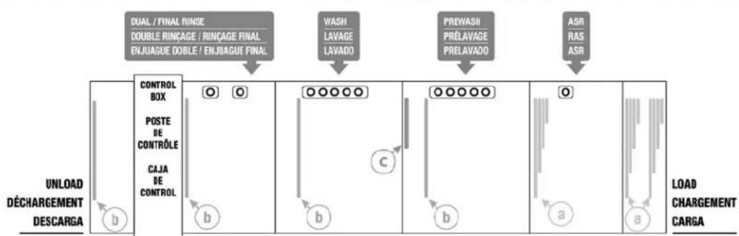
(machine may not be equipped with ASR module)
Left to Right
5' CENTER SECTION I ZONE CENTRALE DE 5 pi (1524 mm) I ZONA CENTRAL DE 5'
flowchart
graph TD
    A["ASI / RAS / ASB"] --> B["PREWASH / PRELAVAGE / PRELAVADO"]
    B --> C["WASH / LAVAGE / LAVADO"]
    C --> D["DUAL / FINAL RINSE / DOUBLE RINÇAGE / RINÇAGE FINAL / ENJUAGUE DOBLE / ENJUAGUE FINAL"]
    D --> E["BLOWER DRYER / TUNNEL DE SÉCHAGE / SECADOR DE AIRE"]
    F["LOAD CHARGEMENT CARGA"] --> G["a"]
    G --> H["a"]
    H --> I["b"]
    I --> J["b"]
    J --> K["o"]
    K --> L["o"]
    L --> M["o"]
    M --> N["CONTROL BOX"]
    M --> O["POSTE DE CONTROLE"]
    M --> P["CAJA DE CONTROL"]
    Q["UNLOAD DÉCHARGEMENT DESCARGA"] --> R
Right to Left
5' CENTER SECTION | ZONE CENTRALE DE 5 pi (1524 mm) | ZONA CENTRAL DE 5'

flowchart
graph TD
    A["ELOWER DRITER TUNNEL DE SÉOVAGE SECADOR DE AIRE"] --> B["CONTROL BOX"]
    B --> C["POSTE DE CONTRÔLE"]
    C --> D["CAJA DE CONTROL"]
    D --> E["LOAD CHARGEMENT CARGA"]

    F["DUAL / FINAL RINSE DOUBLE RINÇAGE / RINÇAGE FINAL ENJUAGUE DOBLE / ENJUAGUE FINAL"] --> B
    G["WASH LAVAGE LAVADO"] --> B
    H["PREWASH PRÉLAVAGE PRELAVADO"] --> B
    I["ASR RAS ASR"] --> B

    J["UNLOAD DÉCHARGEMENT DESCARGA"] --> B
    K["b"] --> B
    L["b"] --> B
    M["b"] --> B
    N["a"] --> B
    O["a"] --> B
LEGEND | LÉGENDE | LEYENDA

4-PLY CURTAINS
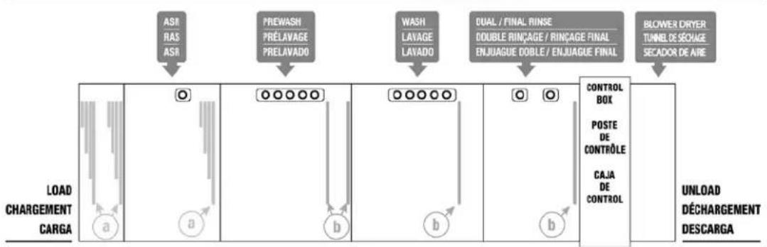
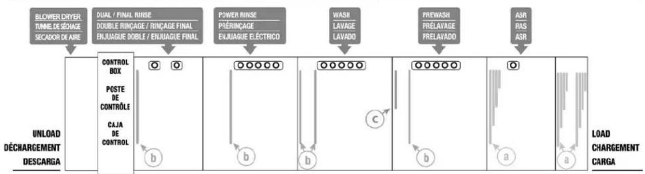
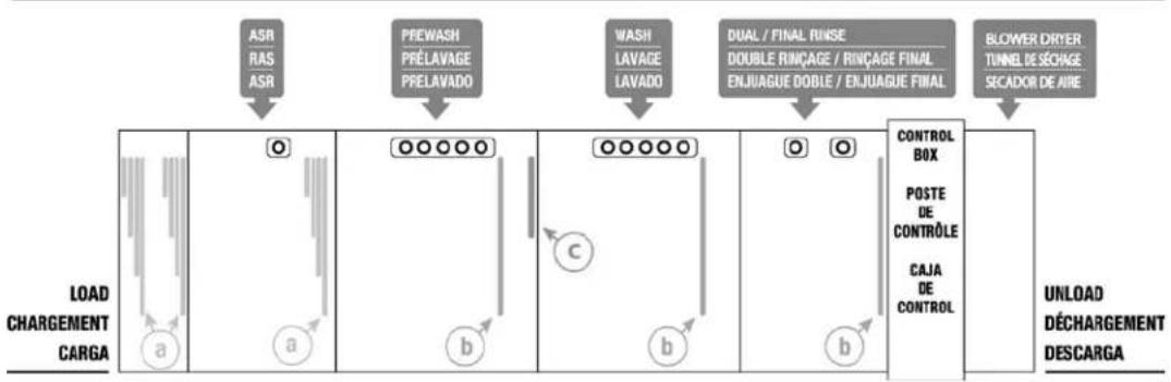
(machine may not be equipped with ASR module)
Left to Right
8' CENTER SECTION | ZONE CENTRALE DE 8 pi (2438 mm) | ZONA CENTRAL DE 8'
flowchart
graph LR
    A["ASR RAS ASR"] --> B["PREWASH PRELAVAGE PRELAVADO"]
    B --> C["WASH LAVAGE LAVADO"]
    C --> D["POWER RINSE PRÉRINÇAGE ENJUAGUE ELÉCTRICO"]
    D --> E["DUAL / FINAL RINSE DOUBLE RINÇAGE / RINÇAGE FINAL ENJUAGUE DOBLE / ENJUAGUE FINAL"]
    E --> F["BLOWER DRYER TUNEL DE ZÉCHAGE SECADOR DE AIRE"]

    subgraph Load CHARGEMENT CARGA
        G["a"] --> H["○"]
        I["a"] --> J["○"]
        K["b"] --> L["○"]
        M["c"] --> N["○"]
        O["b"] --> P["○"]
        Q["b"] --> R["○"]
    end

    subgraph CONTROL BOX
        S["POSTE DE CONTRÔLE"]
        T["CAJA DE CONTROL"]
        U["b"] --> V["○"]
        W["b"] --> X["○"]
    end

    subgraph UNLOAD DECHARGEMENT DESCARGA
        Y["●"]
        Z["●"]
        AA["●"]
        AB["●"]
    end
Right to Left
8' CENTER SECTION | ZONE CENTRALE DE 8 pi (2438 mm) | ZONA CENTRAL DE 8'
flowchart
graph LR
    A["BLOWER DRYER TUNNE DE SÉCHAGE SECADOR DE AIRE"] --> B["DUAL / FINAL RINSE DOUBLE RINÇAGE / RINÇAGE FINAL ENJUAGUE DOBLE / ENJUAGUE FINAL"]
    B --> C["POWER RINSE PRÉRINÇAGE ENJUAGUE ÉLECTRICO"]
    C --> D["WASH LAVAGE LAVADO"]
    D --> E["FREWASH PRÉLAVAGE PRELAVADO"]
    E --> F["ASR RAS ASR"]
    G["UNLOAD DÉCHARGEMENT DESCARGA"] --> H["CONTROL BOX POSTE DE CONTRÔLE CAJA DE CONTROL"]
    H --> I["○ b"]
    I --> J["○ b"]
    J --> K["○ b"]
    K --> L["○ b"]
    L --> M["○ b"]
    M --> N["○ a"]
    N --> O["○ a"]
    O --> P["LOAD CHARGEMENT CARGA"]
FT1000Se-BAS & FT1000Se-EGR (Higher Than Standard)
(machine may not be equipped with ASR module)
Left to Right
5' CENTER SECTION | ZONE CENTRALE DE 5 pi (1524 mm) | ZONA CENTRAL DE 5'
flowchart
graph TD
    A["ASR RAS ASR"] --> B["PREWASH PRÉLAVAGE PRELAVADO"]
    B --> C["WASH LAYAGE LAYADO"]
    C --> D["DUAL/FINAL RINSE DOUBLE RINÇAGE / RINÇAGE FINAL ENJUAGUE DOBLE / ENJUAGUE FINAL"]
    D --> E["CONTROL BOX POSTE DE CONTRÔLE CAJA DE CONTROL"]
    E --> F["UNLOAD DÉCHARGEMENT DESCARGA"]
    subgraph Load CARGA
        G["a"] --> H["a"]
        I["b"] --> J["b"]
        K["c"] --> L["c"]
        M["d"] --> N["d"]
        O["e"] --> P["e"]
        Q["f"] --> R["f"]
    end
Right to Left
5' CENTER SECTION | ZONE CENTRALE DE 5 pi (1524 mm) | ZONA CENTRAL DE 5'
flowchart
graph TD
    A["DUAL / FINAL RINSE"] --> B["DOUBLE RINÇAGE / RINÇAGE FINAL"]
    B --> C["ENJUAGUE DOBLE / ENJUAGUE FINAL"]
    C --> D["CONTROL BOX"]
    D --> E["POSTE DE CONTROLE"]
    E --> F["CAJA DE CONTROL"]
    F --> G["UNLOAD DÉCHARGEMENT DESCARGA"]
    G --> H["Load CHARGEMENT CARGA"]

    I["WASH LAVAGE LAVADO"] --> J["PREWASH PRELAVAGE PRELAVADO"]
    J --> K["ASR RAS ASR"]

    L["○ ○"] --> M["○○○○○"]
    M --> N["○○○○○"]
    N --> O["○"]
    O --> P["a"]
    P --> Q["Load"]
LEGEND | LÉGENDE | LEYENDA

4-PLY CURTAINS
(machine may not be equipped with ASR module)
Left to Right
5' CENTER SECTION | ZONE CENTRALE DE 5 pi (1524 mm) | ZONA CENTRAL DE 5'
flowchart
graph LR
    A["LOAD CHARGEMENT CARGA"] --> B["a"]
    B --> C["O"]
    C --> D["a"]
    D --> E["b"]
    E --> F["O"]
    F --> G["b"]
    G --> H["c"]
    H --> I["b"]
    I --> J["O"]
    J --> K["b"]
    K --> L["CONTROL BOX POSTE DE CONTRÔLE CAJA DE CONTROL"]
    L --> M["BLOWER DRYTER TUNNEL DE SÉCHAGE SECADOR DE AIRE"]
    M --> N["UNLOAD DÉCHARGEMENT DESCARGA"]

    subgraph Process Steps
        A --> O["ASR RAS ASR"]
        B --> P["PREWASH PRÉLAVAGE PRELAVADO"]
        C --> Q["WASH LAVAGE LAVADO"]
        D --> R["DUAL / FINAL RINSE DOUBLE RINÇAGE / RINÇAGE FINAL ENJUAGUE DOBLE / ENJUAGUE FINAL"]
        E --> S["O"]
        F --> T["O"]
        G --> U["O"]
    end
Right to Left
5' CENTER SECTION | ZONE CENTRALE DE 5 pi (1524 mm) | ZONA CENTRAL DE 5'
flowchart
graph TD
    A["BLOWER DRYER TUNNEL DE SÉOVAGE SECADOR DE AIRE"] --> B["DUAL / FINAL RINSE DOUBLE RINÇAGE / RINÇAGE FINAL ENJUAGUE DOBLE / ENJUAGUE FINAL"]
    B --> C["WASH LAVAGE LAVADO"]
    C --> D["PREWASH PRÉLAVAGE PRELAVADO"]
    D --> E["ASR RAS ASR"]
    F["UNLOAD DÉCHARGEMENT DESCARGA"] --> G["CONTROL BOX POSTE DE CONTROLE CAJA DE CONTROL"]
    G --> H["○ ○ b"]
    H --> I["○○○○○ c"]
    I --> J["○○○○○ b"]
    J --> K["○ a"]
    K --> L["Load CHARGEMENT CARGA"]
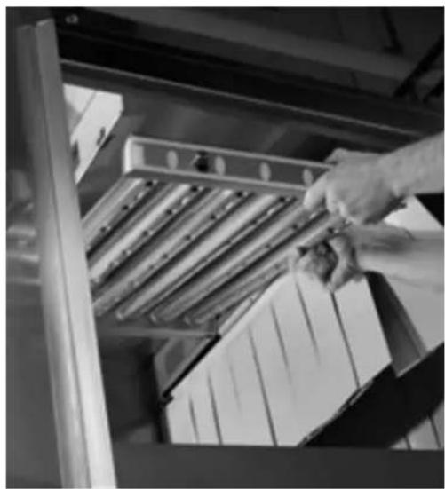
Prewash, Wash, and Power Rinse Arms
Ensure all wash arms are properly installed and wash arm sliders are closed. The tabs on the sides of the arms will drop into the notches in the supports when properly installed (Fig. 50). Adjust locking brackets on lower arms if necessary.
natural_image
Black-and-white photo of a hand placing a small object into a metal rack, with stacked boxes visible (no text or symbols)Fig. 50
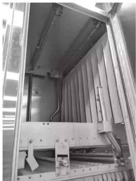
Dual Rinse/Final Rinse Arms
Ensure dual rinse and final rinse arms are properly installed (Fig. 51).
natural_image
Interior view of an industrial equipment cabinet with metal frame and internal components (no visible text or symbols)Fig. 51
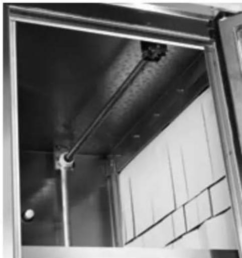
Automatic Soil Removal (ASR) Arms (When Equipped)
Ensure ASR arms are properly installed (Fig. 52).
natural_image
Interior view of a modern building with exposed metal beams and window panels (no visible text or symbols)Fig. 52
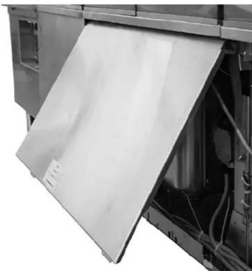
Lower Trim Panels (Front) and Rear Panels
When installing the lower trim panels on the front of the machine, butt each panel end to end. With the bottom of the panel held out on a 45^ angle (Fig. 53), hang the upper lip of the panel over the hooks located just below the doors (Fig. 54). Swing the bottom of the panel down and snap the lower panel clips under the frame.
natural_image
Close-up of a white plastic sheet being opened into a mechanical device (no visible text or symbols)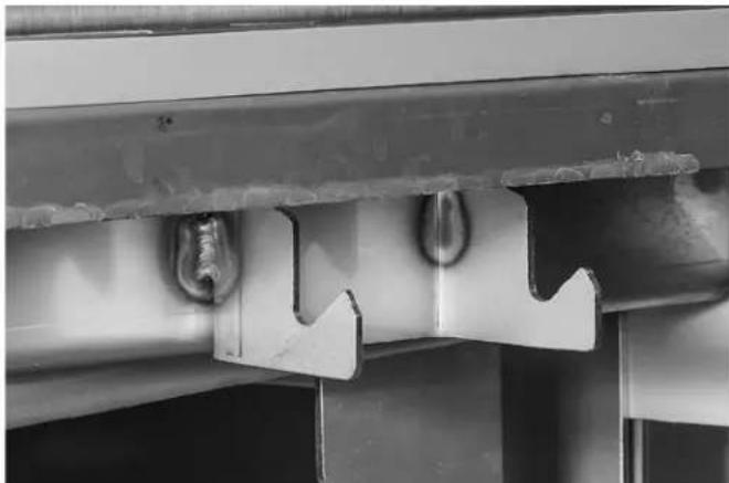
natural_image
Close-up of a metal bracket with two bolts and a zigzag cutout, no visible text or symbolsFig. 53 Fig. 54
When installing the rear panels, butt each panel end to end. Hang upper lip of panel over tabs located on the top panels of the machine. Swing the bottom of the panel down and snap the lower panel clips under the frame.
Calibrating the Electric Booster Thermostat
NOTE: This procedure only needs to be followed once during initial setup.
NOTE: This procedure may be followed during the 20 minute period in the “Adjusting the Conveyor Take-Up Unit (Load Section)” procedure, page 37.
NOTE: This procedure should only be followed if the machine is operational and the booster can be powered on with hot water of at least 105^ F flowing into it.
For the internal Hobart booster, the controlling thermostat needs to be calibrated to the conditions at the customer's site. The calibration is automatic while the machine is running.
To begin calibration, ensure the booster's circuit breaker is set to the "ON" position and power is present at 24CON. Block the photo eyes located at the load end of the machine. Start the machine and allow the machine to run for a minimum of 20 minutes.
NOTE: Do not put ware or any other item on the conveyor during the procedure. This may cause the dish limit arm to trip and stop the conveyor movement. If the conveyor stops for any reason during the 20 minute calibration period, the procedure should be rerun from the beginning to ensure proper calibration.
After 20 minutes, unblock the photo detector. When the final rinse output turns off and the display shows “---” for the final rinse temperature, stop the conveyor. Power off the machine by pressing the POWER button on the keypad. This saves the calibration data and completes the automatic calibration.
Conveyor Gear Motor
The conveyor gear motor is shipped with oil at the proper level in the speed reducer.
Lubricants are available from your local Hobart Service Office.
Delime Indicator Setup
Based on water hardness and final rinse water usage, the machine will calculate and notify the operator when it is time to delime. Refer to FT1000e Operation manual (F-41143) or FT1000e Service Manual (F-45735) to program the 'Delime-Water Hardness' and 'Delime Concentration' settings based on customer's specific water conditions and delime solution being used.
SERVICE
If service is needed on this machine, contact your local Hobart Service Office.
TABLE DES MATIÈRES
REMARQUES À L'INSTALLATEUR....58
COMMENT RÉDUIRE LA HAUTEUR DE PASSAGE DU POSTE DE COMMANDE LORS DU TRANSPORT .....58
COMMENT SUPPRIMER LA RÉCUPÉRATION DE L'ÉNERGIE ET LA STRUCTURE DE VENTILATION POUR UNE HAUTEUR PLUS BASSE....60
DÉBALLAGE 61
natural_image
Technical line drawing of an industrial furnace or oven system with labeled components A and B (no text or symbols beyond labels)Fig. 2
DÉBALLAGE
natural_image
Interior view of a stainless steel industrial machine with multiple vats and cooling fins (no visible text or symbols)Fig. 3
natural_image
Interior view of a mechanical assembly with metal frame and structural supports (no visible text or symbols)Fig. 4
ASSEMBLAGE
natural_image
3D mechanical assembly diagram showing pipe fittings and a cylindrical component with a labeled part (no text or symbols on the main diagram)Fig. 15
natural_image
Mechanical pipe assembly with black and gray components (no visible text or symbols)D - G
natural_image
Mechanical pipe assembly with black and metallic components (no visible text or symbols)G
Fig. 17
Fig. 31
Fig. 32
natural_image
Close-up of a hand handling white plastic vials on a conveyor belt (no visible text or symbols)Fig. 45
natural_image
Black-and-white photo of a hand placing a tray into a storage cabinet (no visible text or symbols)Fig. 50
Gicleurs de double rinçage/rinçage final
natural_image
Interior view of an industrial equipment cabinet with metal frame and internal pipes (no visible text or symbols)Fig. 51
natural_image
Interior view of a modern building with metal beams and a window (no visible text or symbols)Fig. 52
natural_image
Close-up of a white plastic sheet being opened into a mechanical device (no visible text or symbols)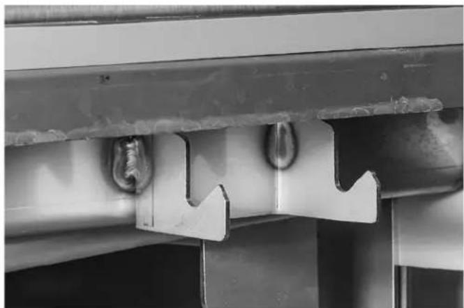
natural_image
Close-up of a metal bracket with two curved notches and a central hole, showing no text or symbols.Fig. 53 Fig. 54
natural_image
Interior view of a stainless steel industrial machine with multiple cylindrical components and mounting brackets (no visible text or symbols)Fig. 3
natural_image
Interior view of a mechanical assembly with metal frame and mounting holes (no visible text or symbols)Fig. 4
ENSAMBLAJE
natural_image
3D mechanical assembly diagram showing pipe fittings and a cylindrical component with a labeled part (no text or symbols on the parts themselves)Fig. 15
natural_image
Mechanical pipe assembly with attached housing and mounting bracket (no visible text or symbols)D-1
natural_image
Mechanical pipe assembly with black and metallic components (no visible text or symbols)|
Fig. 17
Fig. 31
Fig. 32
natural_image
Close-up of a hand handling white plastic vials on a conveyor belt (no visible text or symbols)Fig. 45
flowchart
graph LR
    A["BLOWER DRYER TUNNE DE SÉCHAGE SECADOR DE AIRE"] --> B["DUAL / FINAL RINSE DOUBLE RINÇAGE / RINÇAGE FINAL ENJUAGUE DOBLE / ENJUAGUE FINAL"]
    B --> C["POWER RINSE PRÉRINÇAGE ENJUAGUE ÉLECTRICO"]
    C --> D["WASH LAVAGE LAVADO"]
    D --> E["FREWASH PRÉLAVAGE PRELAVADO"]
    E --> F["ASR RAS ASR"]
    G["UNLOAD DÉCHARGEMENT DESCARGA"] --> H["CONTROL BOX POSTE DE CONTRÔLE CAJA DE CONTROL"]
    H --> I["OUTPUT OUT"]
    I --> J["OUTPUT OUT"]
    J --> K["OUTPUT OUT"]
    K --> L["OUTPUT OUT"]
    L --> M["OUTPUT OUT"]
    M --> N["OUTPUT OUT"]
    N --> O["OUTPUT OUT"]
    O --> P["OUTPUT OUT"]
    P --> Q["OUTPUT OUT"]
    Q --> R["OUTPUT OUT"]
    R --> S["OUTPUT OUT"]
    S --> T["OUTPUT OUT"]
    T --> U["OUTPUT OUT"]
    U --> V["OUTPUT OUT"]
    V --> W["OUTPUT OUT"]
    W --> X["OUTPUT OUT"]
    X --> Y["OUTPUT OUT"]
    Y --> Z["OUTPUT OUT"]
    Z --> AA["OUTPUT OUT"]
    AA --> AB["OUTPUT OUT"]
    AB --> AC["OUTPUT OUT"]
    AC --> AD["OUTPUT OUT"]
    AD --> AE["OUTPUT OUT"]
    AE --> AF["OUTPUT OUT"]
    AF --> AG["OUTPUT OUT"]
    AG --> AH["OUTPUT OUT"]
    AH --> AI["OUTPUT OUT"]
    AI --> AJ["OUTPUT OUT"]
    AJ --> AK["OUTPUT OUT"]
    AK --> AL["OUTPUT OUT"]
    AL --> AM["OUTPUT OUT"]
    AM --> AN["OUTPUT OUT"]
    AN --> AO["OUTPUT OUT"]
    AO --> AP["OUTPUT OUT"]
    AP --> AQ["OUTPUT OUT"]
    AQ --> AR["OUTPUT OUT"]
    AR --> AS["OUTPUT OUT"]
    AS --> AT["OUTPUT OUT"]
    AT --> AU["OUTPUT OUT"]
    AU --> AV["OUTPUT OUT"]
    AV --> AW["OUTPUT OUT"]
    AW --> AX["OUTPUT OUT"]
    AX --> AY["OUTPUT OUT"]
    AY --> AZ["OUTPUT OUT"]
    AZ --> BA["OUTPUT OUT"]
    BA --> BB["OUTPUT OUT"]
    BB --> BC["OUTPUT OUT"]
    BC --> BD["OUTPUT OUT"]
    BD --> BE["OUTPUT OUT"]
    BE --> BF["OUTPUT OUT"]
    BF --> BG["OUTPUT OUT"]
    BG --> BH["OUTPUT OUT"]
    BH --> BI["OUTPUT OUT"]
    BI --> BJ["OUTPUT OUT"]
    BJ --> BK["OUTPUT OUT"]
    BK --> BL["OUTPUT OUT"]
    BL --> BM["OUTPUT OUT"]
    BM --> BN["OUTPUT OUT"]
    BN --> BO["OUTPUT OUT"]
    BO --> BP["OUTPUT OUT"]
    BP --> BQ["OUTPUT OUT"]
    BQ --> BR["OUTPUT OUT"]
    BR --> BS["OUTPUT OUT"]
    BS --> BT["OUTPUT OUT"]
    BT --> BU["OUTPUT OUT"]
    BU --> BV["OUTPUT OUT"]
    BV --> BW["OUTPUT OUT"]
    BW --> BX["OUTPUT OUT"]
    BX --> BY["OUTPUT OUT"]
    BY --> BZ["OUTPUT OUT"]
    BZ --> CA["OUTPUT OUT"]
    CA --> CB["OUTPUT OUT"]
    CB --> CC["OUTPUT OUT"]
    CC --> CD["OUTPUT OUT"]
    CD --> CE["OUTPUT OUT"]
    CE --> CF["OUTPUT OUT"]
    CF --> CG["OUTPUT OUT"]
    CG --> CH["OUTPUT OUT"]
    CH --> CI["OUTPUT OUT"]
    CI --> CJ["OUTPUT OUT"]
    CJ --> CK["OUTPUT OUT"]
    CK --> CR["OUTPUT OUT"]
    CR --> CS["OUTPUT OUT"]
    CS --> CT["OUTPUT OUT"]
    CT --> CU["OUTPUT OUT"]
    CU --> CV["OUTPUT OUT"]
    CV --> CW["OUTPUT OUT"]
    CW --> CX["OUTPUT OUT"]
    CX --> CY["OUTPUT OUT"]
    CY --> CZ["OUTPUT OUT"]
    CZ --> DA["OUTPUT OUT"]
    DA --> DB["OUTPUT OUT"]
    DB --> DC["OUTPUT OUT"]
    DC --> DD["OUTPUT OUT"]
    DD --> DE["OUTPUT OUT"]
    DE --> DF["OUTPUT OUT"]
    DF --> DG["OUTPUT OUT"]
    DG --> DH["OUTPUT OUT"]
    DH --> DI["OUTPUT OUT"]
    DI --> DJ["OUTPUT OUT"]
    DJ --> DK["OUTPUT OUT"]
    DK --> DL["OUTPUT OUT"]
    DL --> DJ
LEGEND | LÉGENDE | LEYENDA

4-PLY CURTAINS
natural_image
Close-up of a hand holding a metal tray with ribbed material inside a storage cabinet (no visible text or symbols)Fig. 50
natural_image
Interior view of an industrial equipment cabinet with metal frame and wiring (no visible text or symbols)Fig. 51
natural_image
Interior view of a building with exposed ceiling and window panels, showing structural beams and a spherical object (no text or symbols visible)Fig. 52
natural_image
Close-up of a kitchen appliance with a white sheet being opened, showing internal components and wiring (no visible text or symbols)Fig. 53 Fig.54
natural_image
Close-up of a metal bracket with two bolts and a zigzag cutout, mounted on a wall (no text or symbols visible)
- HOBART
- TABLE OF CONTENTS
- Installation and Care Of FT1000e SERIES DISHWASHERS SAVE THESE INSTRUCTIONS
- GENERAL
- NOTES FOR THE INSTALLERS
- Read the entire manual before installing the machine.
- HOW TO REDUCE THE CLEARANCE HEIGHT OF THE CONTROL BOX DURING MOVE-IN
- HOW TO REMOVE ENERGY RECOVERY/VENT HOUSING FOR LOW CLEARANCE
- UNPACKING
- Removing Each Section From Its Skid
- NOTICE Do not use a forklift directly on the machine frame or tank to move or lift machine sections. Doing so may result in damage to the machine.
- LOCATION
- Positioning the Center Section
- Leveling the Center Section
- ASSEMBLY
- Rotating Control Box 90 Degrees
- Installing Foam Tape on Chamber Flanges & Control Box Mounting Surface
- Attaching Control Box to Unload Section
- Positioning the Adjacent Load or Unload Sections
- Leveling the Load and Unload Sections
- Joining the Sections Together
- Installing the Curtain Hangers and Unload Air Baffle
- Installing the Saddle Joint - Bottom of Chamber Flanges
- Installing the Flowback Pipe (Wash to Prewash Tanks)
- Installing the Drain Pipe
- For a L-R machine (steps 6-8):
- For a R-L machine (steps 9-11):
- Drain Back Pan Installation
- Blower Dryer Assembly
- Advansys Module Installation
- Control Box Connections
- Electric Booster Heater Wiring
- Door and Drain Interlock Switches (Prewash to Wash Tank)
- Water Supply
- Fill
- Final Rinse
- Drain
- Line Strainers
- Steam Supply (When Equipped)
- Steam Tank Heaters – Condensate Return Lines
- Steam Booster Heater – Condensate Return Line & Relief Valves
- Steam Blower Dryer (When Equipped) – Condensate Return Line
- Fill & Auto Clean (When Equipped) Hose Connections
- Motor Overloads
- Checking Motor Rotation (Three-Phase Motors)
- Separate Electrical Connections
- Voltage Adjustment
- THIS PROCEDURE MUST BE DONE ONLY BY A QUALIFIED HOBART-TRAINED SERVICE TECHNICIAN.
- Electrical Connection - Detergent & Rinse Aid Dispensers
- External Vent Fan Control
- CONVEYOR ASSEMBLY
- Loading and Joining the Conveyor Sections
- Conveyor Offset Side Bar
- Adjusting the Conveyor Take-Up Unit (Load Section)
- FT1000e Conveyor Jam Switch Setting Verification/Adjustment
- MISCELLANEOUS
- Vent
- NOTICE Do not step on top chamber covers when installing vent.
- Air Baffle Settings
- Curtain Configurations
- FT1000e-BAS & FT1000e-EGR (Standard Height)
- (machine may not be equipped with ASR module)
- LEGEND | LÉGENDE | LEYENDA
- FT1000Se-BAS & FT1000Se-EGR (Higher Than Standard)
- Prewash, Wash, and Power Rinse Arms
- Dual Rinse/Final Rinse Arms
- Automatic Soil Removal (ASR) Arms (When Equipped)
- Lower Trim Panels (Front) and Rear Panels
- Calibrating the Electric Booster Thermostat
- Conveyor Gear Motor
- Delime Indicator Setup
- SERVICE
- TABLE DES MATIÈRES
- DÉBALLAGE
- ASSEMBLAGE
- Gicleurs de double rinçage/rinçage final
- ENSAMBLAJE
Brand : Hobart
Model : FT1000e
Category : Industrial dishwasher