DL-230L - Measuring equipment VOLTCRAFT - Free user manual and instructions
Find the device manual for free DL-230L VOLTCRAFT in PDF.



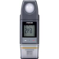
| Product type | Lux meter data logger |
| Brand / Model | Voltcraft DL-230L |
| Measuring range | 0 to 40,000 lux/fc |
| Resolution | 1 lux/fc (up to 9999), 10 lux/fc (beyond) |
| Accuracy | <10,000 lux: ±(3% + 10 pts); ≥10,000 lux: ±(10% + 10 pts) |
| Internal memory | 31,320 measurement values |
| Recording interval | 10 seconds to 24 hours, configurable |
| Display | 4,000 count LCD with backlight |
| Interface | USB 2.0 (USB plug) |
| Protection rating | IP65 (with USB protective cap) |
| Power supply | 1 CR2450 3V lithium button cell |
| Power consumption | Approx. 40 μA during operation |
| Weight | Approx. 53 g |
| Operating conditions | +5 to +40 °C, <80% RH non-condensing |
| Storage conditions | -10 to +60 °C, <70% RH non-condensing |
| Main functions | Illuminance measurement, automatic recording, PDF/CSV reports, LED alarms, multiple start/stop modes |
| Configuration | Online via website or Voltsoft software (CD included) |
| Package contents | Data logger with USB cap, CR2450 battery, CD (manual + software), safety instructions |
| Maintenance and cleaning | Clean with slightly damp antistatic cloth; replace battery when symbol appears; annual calibration recommended |
| Safety | IP65, do not use in explosive areas, avoid strong magnetic fields, follow manual instructions |
| Spare parts and repairability | CR2450 battery (ref. 652028); repairs by authorized technician |
Frequently Asked Questions - DL-230L VOLTCRAFT
User questions about DL-230L VOLTCRAFT
0 question about this device. Answer the ones you know or ask your own.
Ask a new question about this device
Download the instructions for your Measuring equipment in PDF format for free! Find your manual DL-230L - VOLTCRAFT and take your electronic device back in hand. On this page are published all the documents necessary for the use of your device. DL-230L by VOLTCRAFT.
USER MANUAL DL-230L VOLTCRAFT
GB Operating Instructions
Data Logger Lux DL-230L
Item No. 1931527 Page 33 - 63
F Notice d'emploi


C

C


- Introduction......35
- Explanation of symbols....35
- Intended use....36
- Delivery content....36
- Safety instructions ....37
- Overview of parts ....38
- Display elements and symbols 39
- LED Statuses....41
- Before first use....41
a) Remove the protective film....41
b) Inserting the battery....41
- Operation....42
a) USB protective cap....42
b) Connecting the data logger to the computer 42
c) Removing the data logger from the computer 42
- Configuration with software 43
a) Installing the software....43
b) Creating the configuration file....44
- Online configuration with the website 44
a) Overview of the configuration interface 44
b) Measurement - Basic Settings....45
c) Measurement - Alarm Settings 46
d) PDF report options 47
e) Storage options 47
f) Creating/saving the configuration file 48
g) Transferring the configuration file to the data logger 48
h) Checking the configuration settings....48
- Data logger operation modes and displays 49
a) Operation modes and settings....49
b) LC display indication....52
- Logging data....54
a) Preparation....54
b) Calling up the function menu....54
c) Launching logging 54
d) Stopping logging....54
e) Display of the remaining time until recording start/stop....55
f) Enabling/disabling the alarm limit pause function....55
g) Display of the minimum/maximum measured values 56
- Creating a report....57
a) PDF report....57
b) CSV report....57
-
Deleting data....58
-
Updating firmware....58
-
Resetting to the factory settings ....59
-
Cleaning and maintenance....59
a) General information....59
b) Cleaning 59
c) Inserting/changing the battery 59
- Disposal....61
a) Product....61
b) Battery information 61
-
Troubleshooting 62
-
Technical data....63
1. Introduction
Dear customer,
Thank you for purchasing this Voltcraft® product.
Voltcraft ^® produces high-quality measuring, charging and network devices that offer outstanding performance and innovation.
With Voltcraft ^® , you will be able to cope with even the most difficult tasks whether you are an ambitious hobby user or a professional user. Voltcraft ^® offers you reliable technology at an extraordinarily favourable cost-performance ratio.
We are confident that starting with Voltcraft ^® will be the beginning of a long, successful relationship.
We hope you enjoy your new Voltcraft® product!
If there are any technical questions, please contact:
www.conrad.com/contact
2. Explanation of symbols

The symbol with an exclamation mark in a triangle is used to highlight important information in these operating instructions. Always read this information carefully.

The arrow symbol indicates special information and tips on how to use the product.

This product has been CE tested and complies with the necessary national and European regulations.
3. Intended use
The data logger allows measurement of illuminance in lux or foot-candle (fc). The internal memory can automatically store up to 31,320 measured values. The device configuration such as storage interval or different start modes can be programmed online via a web-based user interface. There is no need to install any software. If an online connection is not available, the configuration can also be carried out using the standard software supplied.
The measuring range is 0 – 40000 lux/fc. The data logger interval can be preset from 10 seconds to 24 hours. An LC display shows the current measured value.
The data logger is powered by a commercially available 3 V lithium round-cell battery (type CR2450). Only use batteries of the specified type.
The product is connected to a computer like a commercially available USB removable disc and read there. It automatically creates a graphic report in PDF format and a tabular report in CSV format.
Measurements in potentially explosive atmospheres (Ex) are not allowed. The device is dust-tight and water-jet proof (IP65) when the USB protective cap is fitted.
Using this product for purposes other than those described above may damage the product and result in a short circuit, fire or electric shock. The product must not be modified or reassembled!
Read the operating instructions carefully and keep them in a safe place for future reference.
Always observe the safety information in these instructions.
4. Delivery content
• Data logger with USB protective cap
• CR2450 3 V lithium round-cell battery
- Safety information
• CD with operating instructions and standard software
Up-to-date operating instructions
Download the latest operating instructions via the link www.conrad.com/downloads or scan the QR code. Follow the instructions on the website.


These instructions contain important information on how to use the device correctly. Please read them carefully before using the device for the first time.
Damage caused due to failure to observe these instructions will void the warranty. We do not assume any liability for any resulting damage!
We shall not be liable for damage to property or personal injury caused by incorrect handling or failure to observe the safety information! Such cases will void the warranty/guarantee.
- This device was shipped in a safe condition.
- To ensure safe operation and to avoid damaging the device, always observe the safety information and warnings in these instructions.
- The unauthorised conversion and/or modification of the device is not permitted for safety and certification reasons.
- Consult an expert when in doubt about the operation, safety or connection of the device.
- The meter and its accessories are not toys and must be kept out of the reach of children.
- Always comply with the accident prevention regulations for electrical equipment when using the product in commercial facilities.
- In schools, educational facilities, and hobby and DIY workshops, meters must be used under the responsible supervision of qualified personnel. The same applies when the meter is used by people with reduced physical and mental capabilities.
- Do not use the product in the immediate vicinity of strong magnetic or electromagnetic fields, transmitter aerials or HF generators. These may distort the measurements.
- The product is dust-tight and water jet-proof only when the protective cap is properly attached and the casing completely closed and is suitable for both indoor and outdoor use. The data logger must not be operated with an open battery compartment or without the protective cap.
- Please handle the product carefully. Jolts, impacts or a fall even from a low height can damage the product.
- If you suspect that safe operation is no longer possible, stop using the device immediately and prevent unauthorised use. Safe operation can no longer be assumed if:
- There are signs of damage
- The device does not function properly
- The device was stored under unfavourable conditions for a long period of time
-
The device was subjected to rough handling during transport.
-
Do not switch the device on immediately after it has been brought from a cold room into a warm one. The condensation generated may destroy the product. Allow the device to reach ambient temperature before switching it on.
- Do not leave packaging material lying around carelessly, as it may become a dangerous toy for children.
- Observe the safety information in each section.
6. Overview of parts


1 Light sensor
2 Red LED control light
3 Green LED control light
4 Integrated battery compartment
5 Measurement display (LC display)
6 "DOWN" function button
7 Battery compartment release button
8 "ENTER" function button
9 Battery compartment rubber seal
10 USB protective cap rubber seal
11 USB plug
12 USB protective cap
7. Display elements and symbols
The following symbols and information are shown on the display (5). Below you will find the list of symbols and their meaning.
| Icon Meaning | |
 | Status indicator: Measured values are within the limits defined during configuration. |
| No high/low alarm is set. | |
 | Alarm indicator: Measured values are exceeding the limits defined during configuration. |
 | Recording has been stopped. |
 | Recording video. |
 | Recording has been paused. |
 | Device is ready to record: Device is configured, and recording has not started yet. It will disappear when the data logger records. |
 | Battery symbol: Full battery capacity |
 | Battery symbol: Sufficient battery capacity |
 | Battery symbol: Low battery capacity, replace the battery |
| Lux | SI unit of illuminance |
| Fc | Imperial unit of illuminance (foot candle) |
| x10 | Multiplier x10 |
| ID | Logger ID |
| MAX | Largest measured value |
| MIN | Smallest measured value |
| USB | Connected to computer. |
| USB PDF | Connected to computer and generating PDF report. |
| PAUSE | Indicates that the pause function is enabled for the alarm limit. |
| MODE START | Indicates that a start mode has been chosen. It will be shown before recording starts. |
| MODE STOP | Indicates that a stop mode has been chosen. It will be shown before recording ends. |
| TIME START | Indicates remaining time before start of recording. |
| TIME STOP | Indicates remaining time until end of recording. |
| Strt | Ready to start recording by holding down the “ENTER” button (8) for a few seconds. (When configuring, select “Logging start condition”: “Start upon Keypress”) |
| Stop | The recording can be stopped by holding down the “ENTER” button (8) for a few seconds. (When configuring, select “Logging end condition”: “Stop button”) |
| on | Ready to enable the limit pause function by holding down the “ENTER” button (8) for a few seconds. |
| off | Ready to disable the limit pause function by holding down the “ENTER” button (8) for a few seconds. |
| d | Days, unit for remaining time. (If the remaining time is below one day, remaining time is shown in HH:MM format.) |
| up | Ready to upgrade firmware. |
| ol | Measurement error |
| Measured values are beyond the measuring range. | |
| Err1 | Configuration error. An error occurred during configuration. Repeat the configuration process. |
8. LED Statuses
The device status is displayed using two LED indicator lights. The LEDs (2 and 3) are located above the display. A list of indicator lights and their meanings can be found below.
| LED Indicator Light Meaning | |
| The green LED (3) flashes. The measured value(s) is/are within the configured lower and upper alarm limits. | |
| The red LED (2) flashes. Memory is full. | |
| The measured value(s) exceed(s) the configured lower and upper alarm limits. | |
| In “Start upon keypress” or “Stop time” mode, recording has been terminated. (In order to start recording again, re-configure the data logger.) | |
| In “Start upon keypress” mode, the data logger is ready to start recording. (To start recording, press and hold down the “ENTER” button (8) for a few seconds.) | |
| The red LED (2) glows steadily. Data logger is generating a PDF report. | |
| The green LED (3) flashes twice. Configuration was successful. | |
| No LED light is on. LED alarm was disabled during configuration. | |
9. Before first use
a) Remove the protective film
- The display has a thin protective film that protects it from scratches during transport. Remove the protective film before using the data logger.
b) Inserting the battery
- Before first use, be sure to insert the supplied battery into the data logger. The “Cleaning and maintenance” chapter explains how to insert the battery properly in detail.
10. Operation
a) USB protective cap

The data logger is only dust-tight and water-jet proof when the USB protective cap (12) is attached. Always keep the two rubber seals (9, 10) clean to ensure the seal functions properly. This protection allows permanent logging in damp rooms and outdoors.
- Remove the USB protective cap (12) only when replacing the battery or connecting the data logger to a computer.
- Remove the USB protective cap by taking it off of the data logger. The USB protective cap fits relatively tightly because of the rubber seal (10).
- Firmly replace the USB protective cap onto the data logger.
b) Connecting the data logger to the computer
- Remove the USB protective cap (12) from the data logger.
- Connect the data logger to an available USB port on your computer. If possible, use a USB extension cable (not included) to avoid mechanical stress on the USB port. This also facilitates reading the data logger display.
- The computer detects new hardware. The model type of your data logger appears as removable data storage on your computer.

In measuring mode, the hardware detection can take up to 2 minutes, because the report will generate automatically (“USB PDF” appears on the display) after inserting. After that, the data logger is connected to the computer.
c) Removing the data logger from the computer
- Disconnect the data logger from your computer system. Remove the data logger from the USB port.
- Replace the USB protective cap on the data logger.
11. Configuration with software
After inserting the battery, configure the data logger either with software or online through the website. Online configuration does not require software installation.
When configuring, select logging parameters such as sample rate, start time, recording duration, pause function, LED flash interval, enable/disable LC display, and PDF report settings.
→ Configuration terms and commands may differ between the software and the website.
The following instructions and explanations are based on the terms and commands found on the configuration website.
a) Installing the software
- Insert the software CD into the DVD drive of your computer.
- The installation will start automatically. If it does not, go to your DVD drive directory, and open the installation file "autorun.exe".
- Choose your desired language.
- Follow the on-screen instructions to complete the installation. Depending on your operating system, a restart may be required.
- For more information, refer to the software operating instructions on the CD (section 3).
- The supplied software is the Voltsoft standard version. The professional version (Voltsoft data logger, part no. 101333) is a separate, optional accessory. If you buy the professional version, you will receive a licence key that unlocks the standard version. Follow the steps in the Voltsoft operating instructions to register and upgrade to the professional version.
Overview of the software features (x = available, - = not available)
| Features Standard Professional | ||
| User Management - x | ||
| E-mail Management - x | ||
| General Settings x x | ||
| Language Settings x x | ||
| E-mail Template - x | ||
| Device Management (Add/Remove) | x x | |
| Custom Graph | - x |
b) Creating the configuration file
- Connect the data logger to your computer.
- Launch the Voltsoft software and follow the operating instructions in the software manual (section 6 and choose your supported device).
• After creating the configuration file, save it locally on your computer and copy the file to the data logger. - Disconnect data logger from your computer.
12. Online configuration with the website
After inserting the battery, configure the data logger either with software or online through the website. Online configuration does not require software installation.
When configuring, select logging parameters such as sample rate, start time, recording duration, pause function, LED flash interval, enable/disable LC display, and PDF report settings.
There are three ways to open the configuration website:
- Open www.conrad.com in a browser and navigate to the product page using the article number of the data logger (1931527). Click on the link for the configuration website to open the website.
• In an Internet browser, open the following Internet address: http://datalogger.voltcraft.com/ConfigBuilder/index.jsp - Connect the data logger to your computer and wait until it has been connected as a removable disc. Open the data logger drive on your computer. Click on the "Configuration Website.html" link to open it.
a) Overview of the configuration interface
The configuration interface consists of three areas.
General Settings:
At the top right, you can set languages by clicking on country flags. Click on your country flag to switch to the national language.
Below, you can select the model type. Select type "DL-230L" from the list and click on it.
Measurement
In this area you can select all basic settings and logging parameters for the data logger.
PDF area options
In this area, you can enter all parameters for PDF report generation.
Storage options
You can use the three lower selection fields "Create Configuration", "Load Setting" and "Default" to save, load or reset the configurations to defaults.
b) Measurement - Basic Settings
| Logger ID (000 ~ 9999) | Logger ID is a four digit identifier. Enter a number between 0000 and 9999 e.g. 0014.Use different logger IDs to identify data loggers with e.g. different configuration files for different usages. |
| Logging start conditions Select one of the following options to determine when the data logger starts recording. Each option has a default stop setting. | |
| “Immediately after memory is full”Data logger starts recording data immediately until the memory is full. | |
| “Start upon keypress”The data logger will start recording if you press and hold down the “ENTER” button (8) for a few seconds. Data logger stops recording when the memory is full. | |
| “Start at start time”Data logger starts recording at a defined date and time until the memory is full. | |
| “Start/Stop time”Data logger starts and stops recording data at a defined date and time. | |
| “Continuous logging”Data logger starts recording immediately and loops. The most recent data overwrite the oldest data.The recording/logging will stop as soon as the battery is empty or the configuration is changed to another “condition”. | |
| Logging end conditions Select one of the following options to determine when the data logger stops recording. | |
| “None”No stop condition is specified. The data logger will stop recording according to the “Logging start conditions” setting. | |
| “Stop button”The data logger will stop recording if you press and hold down the “ENTER” button (8) for a few seconds. | |
| “After PDF creation”Data logger stops recording after PDF report is generated. | |
| Start time Define date and time to start recording data. | |
| End time Define date and time to stop recording data. | |
| Start delay in minutes Define delay to immediate start of recording. | |
| Sample rate Specify the intervals at which the data logger will perform measurements and save data (from 10 seconds to 24 hours).→When operating the data logger at extremely low temperatures, choose a longer sample rate to reduce power consumption and thus extend battery life. | |
| Recording duration This value is automatically calculated based on the sampling rate and cannot be set by the user. | |
| LED flash interval Select how fast the LED control lights (2, 3) should flash. Choose an interval of 5, 10, 15, 20, 25 or 30 seconds. | |
| Enable display Uncheck the box to turn off the LC display, or check the box to turn on the LC display.→When operating the data logger at extremely low temperatures, choose a longer sample rate to reduce power consumption and thus extend battery life. | |
c) Measurement - Alarm Settings
| Enable LED alarm The LED | alarm indicates when a measured value is outside the defined range.To disable the LED alarm, uncheck the box.To enable the LED alarm, check the box.→When operating the data logger at extremely low temperatures, disable the LED alarm to reduce power consumption and thus extend battery life. |
| Pause function limit value D | During recording, the limit alarm can be suspended.Select “Enable” or “Disable”.The pause function does not stop the recording. |
| Illuminance If this box is checked, you can enter an illuminance value in the “Low Alarm” and “High Alarm” fields. You can also choose the unit of measurement (lux/fc). | |
| Low alarm Lower alarm value for the illuminance. | |
| High alarm Upper alarm value for the illuminance. | |
d) PDF report options
| Language Select the language | in which the PDF report should be displayed from the selection box. |
| PDF file name Click on “Insert name” to define the pattern of the file name. Here, you can specify the content fields and the order of the file name.Click on “Delete” to delete all current elements. The field “File name” will be empty again.Select the appropriate elements in the desired order (owner/serial ID/model name/date/time/location).Up to six elements can be chosen. Selected elements appear in the field “File name”.To save the pattern for the file name and close this window, click on the close symbol “x” in the top right corner. | |
| Data format Select your preferred date format from menu.DD = day, MM = month, YYYY = year | |
| Time format Select between 12 hour or 24 hour format. | |
| Owner(max. 32 characters) | Enter the name of the owner/user. |
| Location(max. 32 characters) | Enter the location name such as the name of the location where you will perform measurements. |
| Report name(max. 40 characters) | Enter a report name for the PDF report. |
| User text(max. 40 characters) | Enter some notes or additional information if needed. |
e) Storage options
| Create configuration Create | the configuration file, save it on your computer and install it on the data logger.For further instructions, refer to “f) Creating/saving the configuration file” and “g) Transferring the configuration file to the data logger”. |
| Load settings | Load a previous configuration file (if available) to check the details of this file on the web page.-- A new window appears. -- Select a configuration file that you have previously created and saved on your computer. |
| Standard Reset the settings | to default values and settings. |
f) Creating/saving the configuration file
- After completing the configuration settings, select "Create configuration" to save the configuration file on your computer.
- A new window appears to change the configuration file name. Default name is "SetLog". If needed, change the name of the file.
- Confirm the file name by clicking "Create configuration". Your configuration file will be saved on your computer in the downloads folder.
g) Transferring the configuration file to the data logger
- Remove the USB protective cap from the data logger.
- Connect the data logger to your computer and wait until it has been recognised as a removable disc.
- Drag and drop the configuration file from the download folder of your computer to the data logger folder to execute the configuration.
- The green LED indicator light (3) will flash twice if the configuration file has been successfully installed on the data logger.
- When the data logger is configured, disconnect the data logger from your computer.
h) Checking the configuration settings
- Start mode is based on the configuration setting "Record start condition".
- To check which start mode is enabled, load the existing configuration file into the web interface, check the PDF report or call up the function menu of the data logger.
- Stop mode is based on the configuration "Logging end condition".
- To check which stop mode is enabled, load the existing configuration file into the web interface or call up the function menu of the data logger.
- For further instructions on calling up the function menu, refer to chapter "14 b) Calling up the function menu".
13. Data logger operation modes and displays
a) Operation modes and settings
To make the configuration easier, 13 common operation modes are listed here. To make the following configuration settings, refer to chapter "12 b) Measurement - basic settings".
Mode 1
| Feature Logging starts | immediately. |
| Logging stops when memory is full. | |
| Setting • As “Logging start condition”, select: “Immediately after memory is full” | |
Mode 2
| Feature Logging starts | immediately.The logging will stop if you press and hold down the “ENTER” button (8) for a few seconds. |
| Setting • As “Logging start condition”, select: “Immediately after memory is full”• As “Logging end condition”, select: “Stop button” | |
Mode 3
| Feature Logging starts | immediately. Logging stops after PDF report is generated. |
| Setting • As “Logging start condition”, select: “Immediately after memory is full” • As “Logging end condition”, select: “After PDF creation” | |
Mode 4
| Feature | The logging will start if you press and hold down the “ENTER” button (8) for a few seconds. Logging stops when memory is full. |
| Setting • As “Logging start condition”, select: “Start upon keypress” | |
Mode 5
| Feature | The logging will start and stop if you press and hold down the “ENTER” button (8) for a few seconds. |
| Setting • As “Logging start condition”, select: “Start upon keypress”• As “Logging end condition”, select: “Stop button” | |
Mode 6
| Feature | The logging will start if you press and hold down the “ENTER” button (8) for a few seconds. Logging stops after PDF report is generated. |
| Setting • As “Logging start condition”, select: “Start upon keypress” • As “Logging end condition”, select: “After PDF creation” | |
Mode 7
| Feature Logging starts at defined time. Logging stops when memory is full. |
| Setting • As “Logging start condition”, select: “Start at start time”• Define recording start date and time in field “Start time”. |
Mode 8
| Feature Logging starts | at defined time.The logging will stop if you press and hold down the “ENTER” button (8) for a few seconds. |
| Setting • As “Logging start condition”, select: “Start at start time”Define recording start date and time in field “Start time”.As “Logging end condition”, select: “Stop button” | |
Mode 9
| Feature Logging starts | at defined time. |
| Logging stops after PDF report is generated. | |
| Setting • As “Logging start condition”, select: “Start at start time”• Define recording start date and time in field “Start time”.• As “Logging end condition”, select: “After PDF creation” | |
Mode 10
| Feature Logging starts and stops at defined time. | |
| Setting • As “Logging start condition”, select: “Start/Stop time”Define recording start date and time in field “Start time”.Define recording stop date and time in field “Stop time”. |
Mode 11
| Feature The data are logged immediately and in an infinite loop.The logging will stop as soon as the battery is empty or the configuration is replaced by another “Logging start condition”. |
| Setting • As “Logging start condition”, select: “Continuous logging” |
Mode 12
| Feature The data are logged immediately and in an infinite loop.For an additional stop mode, select: The logging will stop if you press and hold down the “ENTER” button (8) for a few seconds. |
| Setting • As “Logging start condition”, select: “Continuous logging”• As “Logging end condition”, select: “Stop button” |
Mode 13
| Feature The data are logged immediately and in an infinite loop.For an additional stop mode, select: Logging stops after PDF report is generated. |
| Setting • As “Logging start condition”, select: “Continuous logging”• As “Logging end condition”, select: “After PDF creation” |
For modes 1 through 13, you can use additional functions for the delay of the logging start time. When configuring, enter a value under "Start delay in minutes".
b) LC display indication
- Some settings are not indicated on the LC display. To check the settings, refer to chapter "12 h) Checking the configuration settings".
- If there is not any display indicator or once the data logger starts/stops recording, the latest measurement is shown on the display.

| Mode Start mode Stop mode Remarks | |||
| 1 No display indicator Not applicable The red LED (2) flashes when the memory is full. | |||
2 No display indicator To stop the record hold  | down the “ENTER” button (8) for a few seconds. | ||
| 3 No display indicator No display indicator | |||
4 Not applicable 2) flashes when the memory is full.  | To start the recording, press and hold down the “ENTER” button (8) for a few seconds. | ||
5 To start and stop the recording, press  | down the “ENTER” button (8) for a few seconds. | ||
6 No display indicator To start the recording, press and hold down the “ENTER” button (8) for a few seconds.  | |||
7 Not applicable The red LED (2) flashes when the memory is full.  | |||
8 To stop the recording press and hold down the “ENTER” button (8) for a few seconds.  | “ENTER” button (8) for a few seconds.  | ||
| 9 No display inc |  | ||
| 10 |  |  | |
| 11 No display indicator Not applicable | |||
| 12 No display indicator To stop the rec |  | hold down the “ENTER” button (8) for a few seconds. | |
| 13 No display indicator No display indicator | |||
| “Start delay in minutes” | |||
 | Depends on modes 1 – 13 | ||
14. Logging data

The data logger is only dust-tight and water-jet proof when the USB protective cap (12) and the rubber seals (9, 10) are attached. This protection allows permanent logging in damp rooms and outdoors.
Before use, make sure that the USB protective cap is firmly attached to the data logger and the casing is completely closed.
Do not immerse it in water!
Avoid operation near strong magnetic fields.
a) Preparation
- Ensure that rubber seals are in the correct positions and that the cap is firmly attached to the data logger. Place the data logger at the intended location. Position the data logger so that its light sensor (1) faces the light source at an angle of 90°. Keep a safe distance from hot light sources. Heating up the data logger may cause a measurement error (see technical data, operating conditions).
- Remove the protective cap to insert/replace the battery or to read the data stored on a computer. Remove the protective cap from the device.
- Attach the protective cap firmly onto the data logger before the next recording.
b) Calling up the function menu
- To call up the function menu, press the "DOWN" button (6).
- Press the "DOWN" button (6) repeatedly to display the last logged measurements in succession, the logger ID and the start/stop mode selected during the configuration.
c) Launching logging
- The start time of the recording depends on the configuration for "Logging start conditions".
- When the data logger starts logging, " " appears on the LC display (5).
- "P" indicates that the data logger is ready for recording; it goes off as soon as the data logger starts recording.
d) Stopping logging
- The recording stops depending on the configuration for "Logging end conditions".
- If "None" is selected as the logging end condition, recording might stop depending on the "Logging start conditions" setting.
- When the data logger stops logging, "Appears on the LC display (5).
e) Display of the remaining time until recording start/stop
- To call up the function menu, press the "DOWN" button (6).
- Press the "DOWN" button (6) repeatedly until "TIME START" or "TIME STOP" and the remaining time (in hours/minutes or days) appear on the LC display.
Time durations below 24 hours are displayed in HH:MM format.
If the remaining time exceeds 24 hours, it will be displayed in days: “d”.
- Once the recording starts/stops, the latest measurement is shown in the display.
- To go back to the function menu, press the "DOWN" button (6).
f) Enabling/disabling the alarm limit pause function
To enable/disable the alarm limit pause function during recording, the alarm limit must be enabled during the configuration (see chapter "12 c) Measurement - Alarm Settings").
 |  |  |
 |  |  |
To enable/disable the limit pause function, press and hold down the "ENTER" button (8) for a few seconds.
Once the alarm pause function is enabled/disbaled, the latest measurement will be shown in the display.

Recorded values during activated pause function are shown in the report graph as usual. However, the graph clearly shows when and for how long the pause function was enabled.
When the limit pause function is enabled during recording, there is no alarm indicator “√” or “✗”. The LED alarm status and the minimum and maximum values are not updated.
g) Display of the minimum/maximum measured values
 | Briefly press the “ENTER” button (8) → |  | Briefly press the “ENTER” button (8) → |  |
- Press the "ENTER" button (8) to call up the read mode for the maximum and minimum values.
- Press the "ENTER" button (8) to toggle between the maximum and minimum measured values in the selected recording and to go back to the normal measurement display. Each time you press the button, the display toggles.
→ "MAX" indicates maximum value and "MIN" indicates minimum value.
Maximum and minimum measurements are recorded from the moment recording starts.
The data logger checks and updates the last measured value(s) on the display unless the limit pause function has been enabled.
Maximum and minimum readings will stop updating when the device stops logging.
15. Creating a report
a) PDF report
The PDF report contains general information about the device, data logger settings, alarm status, minimum/maximum values, and a graph showing the measured values over the logged time.
- Connect the data logger to your computer.
- A PDF report is produced automatically. The red LED (2) goes on and "USB PDF" appears on the LC display (5). Do not disconnect the data logger from your computer during this period.
- Once the PDF file has been generated successfully, "PDF" disappears from the LC display (5). "USB" remains on the LC display. After creating the report, the data logger will be recognised by the computer as a removable disc.
- Open the data logger drive on your computer.
- Select and open the PDF file.
- The PDF report contains general device information, data logger settings, alarm statuses and a graph showing the measured values during the recorded time.
- Save the PDF file on your computer and close the file.
- Disconnect data logger from your computer.
→ Generating the PDF file can take about 30 seconds depending on the number of measurements saved.
The PDF report contains only the highest and lowest measured values recorded during logging (not during the pause function).
b) CSV report
The CSV report shows all measured values during recording in tabular form. These data can be used to create various evaluations and protocols by means of spreadsheet programs. The CSV report and the PDF report are generated simultaneously. The procedure is identical to the generation of the PDF report.
16. Deleting data
→ Generate and save the PDF report before deleting measured data, if needed.
Deleting data does not affect the configuration settings.
- Press and hold down the "DOWN" (6) and "ENTER" (8) buttons and connect the data logger to your computer. "USB" is shown in the LC display. All data is deleted.
- Release the buttons. The data logger is recognised as a removable disc.
- The data logger folder on your computer is empty, which means that all data have been deleted successfully. Disconnect data logger from your computer.
17. Updating firmware
Download the latest data logger firmware from the product page on www.conrad.com.
Press the "DOWN" button (6) repeatedly until the four-digit logger identifier and "ID" appear on the display.
Press and hold down the "ENTER" button (8) until the four-digit logger ID is replaced by "up".

- Connect the data logger to your computer.
- Drag and drop the firmware to the data logger drive on your computer.
- Data logger starts upgrading. During this time, the data logger will briefly not be displayed as a removable disc. Do not disconnect data logger from your computer!
- As soon as the data logger appears again as a removable disc, the update is completed. Green LED control light flashes twice.
- Disconnect the device from your computer.
The firmware version of the data logger can be checked in the left bottom corner of the PDF report.
18. Resetting to the factory settings
When resetting to factory settings, all previously defined configuration settings are deleted. In this case, the stored measured values are not affected. The measured values are retained.
- Remove the battery, as described in section "19 c) Inserting/changing the battery".
- Press and hold down the "DOWN" button (6) and connect the data logger to your computer. As soon as the green LED (3) goes on, release the "DOWN" button (6).
- Wait a few minutes until the computer recognises the data logger as a removable disc. The data logger is reset to factory defaults.
- Configure the data logger as described in chapter "11 or 12 Configuration".
19. Cleaning and maintenance
a) General information
To ensure the accuracy of the data logger over a long period of time, it should be calibrated at least once a year.
The meter does not need to be serviced (apart from occasional cleaning and replacing the battery).
Refer to the following sections for instructions on how to change the battery.

Regularly check the device for technical safety, for example, for damage to the casing or deformation, etc.
b) Cleaning
Do not use abrasive detergents, petrol, alcohol or other similar chemicals to clean the device. These may corrode the surface of the meter. In addition, the vapours emitted by these substances are explosive and harmful to your health. Do not use sharp-edged tools, screwdrivers or metal brushes to clean the device.
To clean the device and the display, use a clean, lint-free, antistatic and slightly damp cleaning cloth. Allow the device to dry completely before using it again.
c) Inserting/changing the battery
A CR2450 3 V lithium round-cell battery is required to operate the meter. Before first use or when the battery change symbol “ ^1 ” appears on the display, be sure to insert a new, fully charged battery.
→ Changing the battery will not delete any data or settings.
Proceed as follows to insert/replace the battery:
- Remove the protective cap (12) from the data logger.
- Press and hold down the battery compartment release button (7) and gently take the logger unit out of its casing. The logger unit sits relatively firmly in the casing thanks to the second rubber seal (9).
- Flip over the logger unit. The battery compartment (4) is located on the back of the logger unit. Be careful not to touch the display, as there is no protective cover on it.
- Replace the flat battery with a new one of the same type. Insert the new battery (CR2450) into the battery compartment, observing the correct polarity. Refer to the polarity markings in the battery compartment. The positive pole of the battery has to face outwards. Inserting the battery will be easier if you first insert it sideways into the battery compartment where the side contact is located.
- Push the logger unit back into the casing in the correct direction. Make sure that the LC display aligns with the window of the casing. Close the casing carefully until the logger unit clicks into place.
- Place the protective cap back onto the data logger.


Do not leave empty batteries in the device. Even leakproof batteries may corrode and destroy the device or release chemicals that are harmful to your health.
Do not leave batteries unattended. They may be swallowed by children or pets. Seek immediate medical attention if a battery is swallowed.
If you do not plan to use the meter for an extended period, remove the battery to prevent it from leaking.
Leaking or damaged batteries may cause acid burns if they come into contact with your skin. Always use protective gloves when handling leaking or damaged batteries.
Ensure that the batteries are not short-circuited. Do not throw batteries into fire!
Do not recharge or disassemble non-rechargeable batteries. This may cause a fire or explosion.

You will receive a suitable lithium round-cell battery with the following item number: item no. 65202 (please order one battery).
20. Disposal
a) Product

Electronic devices are recyclable waste and must not be disposed of in the household waste. At the end of its service life, dispose of the product according to the relevant statutory regulations. Remove any inserted batteries and dispose of them separately from the product.
b) Battery information

You as the end user are required by law (Battery Ordinance) to return all used batteries/rechargeable batteries. Disposing of them in the household waste is prohibited.
Contaminated (rechargeable) batteries are labelled with this symbol to indicate that disposal in the domestic waste is forbidden. The abbreviations for heavy metals in batteries are: Cd = Cadmium, Hg = Mercury, Pb = Lead (name on (rechargeable) batteries, e.g. below the trash icon on the left).
Used (rechargeable) batteries can be returned to collection points in your municipality, our stores or wherever (rechargeable) batteries are sold.
You thus fulfil your statutory obligations and contribute to environmental protection.
21. Troubleshooting
With the data logger, you have purchased a product that has been designed according to the latest state of the art and is reliable in operation.
However, problems and malfunctions may still occur.
This section tells you how to troubleshoot common issues:
| Error Solution | |
| The computer does not recognise the data logger. | Check if “USB” is displayed on the data logger after connection. If not, connect it to another USB port. |
| Check if the function for the use of the USB removable disc is enabled on your computer. | |
| A PDF file is not generated. Check w | whether data logger has been recognised by your computer. |
| Check if the data logger is displayed as a removable disc on your com-puter. | |
| Check if the data logger is performing a firmware update. | |
| Unrealistic information on the LC display. | Reset the data logger to factory defaults. |
| The ENTER/DOWN buttons do not respond when they are pressed. | |
| LC display is off. Check if the LC display has been disabled during the configuration. | |
| No LED alarm. Check if the LED alarm has been disabled in the configuration file. | |

Any repair work other than that described above must be carried out by an authorised technician. If you have questions about the meter, please contact our technical support team.
22. Technical data
Measured value......illuminance in lux or foot candle (fc)
Measuring range....0 - 40000 lux/fc
Resolution....1 lux/fc, 10 lux/fc
Accuracy....< 10000 lux: ±(3% + 10 counts)
$$ \geq 10000 \text{ lux:} \pm (10\% + 10 \text{ counts}) $$
Display....4000 Counts (digits)
Display update....10 seconds
Sample rate/measurement interval......10 seconds to 24 hours, stepless
Memory....31,320 measured values
Interface....USB 2.0 connector
Protection class IP65 dust-tight and water-jet proof
(with attached USB protective cap)
Power supply....1x CR2450 3 V lithium round-cell battery
Current consumption......nominal approx. 40 μA (data logger operation)
Operating conditions....+5 to +40 °C (+41 to +104 °F)
<80% relative humidity, non-condensing
Storage conditions....-10 to +60 °C (+14 to +140 °F)
<70% relative humidity, non-condensing
Weight ....approx. 53 g
Dimensions (L x W x H)....110 x 37 x 19 (mm)
Measuring tolerances
Accuracy in ± (% of reading + display error in counts (= number of smallest points)). These accuracy readings are valid for one year at a temperature of +23 °C ( ± 5 °C) and a relative humidity of less than 75% (non-condensing). Temperature coefficient: +0.1 x (specified accuracy)/1 °C.
The accuracy of measurements may be affected when the device is used in a high-frequency electromagnetic field.
Page
France (email): technique@conrad-france.fr


C

C


Dimensions (L x l x h)....110 x 37 x 19 mm

This is a publication by Conrad Electronic SE, Klaus-Conrad-Str. 1, D-92240 Hirschau (www.conrad.com).
All rights including translation reserved. Reproduction by any method, e.g. photocopy, microfilming, or the capture in electronic data processing systems require the prior written approval by the editor. Reprinting, also in part, is prohibited. This publication represent the technical status at the time of printing. Copyright 2019 by Conrad Electronic SE.
- Introduction
- Explanation of symbols
- Intended use
- Delivery content
- Up-to-date operating instructions
- Overview of parts
- Display elements and symbols
- LED Statuses
- Before first use
- a) Remove the protective film
- b) Inserting the battery
- Operation
- a) USB protective cap
- b) Connecting the data logger to the computer
- c) Removing the data logger from the computer
- Configuration with software
- a) Installing the software
- b) Creating the configuration file
- Online configuration with the website
- a) Overview of the configuration interface
- General Settings:
- Measurement
- PDF area options
- Storage options
- c) Measurement - Alarm Settings
- d) PDF report options
- e) Storage options
- f) Creating/saving the configuration file
- g) Transferring the configuration file to the data logger
- h) Checking the configuration settings
- Data logger operation modes and displays
- a) Operation modes and settings
- b) LC display indication
- Logging data
- a) Preparation
- b) Calling up the function menu
- c) Launching logging
- d) Stopping logging
- e) Display of the remaining time until recording start/stop
- f) Enabling/disabling the alarm limit pause function
- g) Display of the minimum/maximum measured values
- Creating a report
- a) PDF report
- b) CSV report
- Deleting data
- Updating firmware
- Resetting to the factory settings
- Cleaning and maintenance
- a) General information
- b) Cleaning
- c) Inserting/changing the battery
- Proceed as follows to insert/replace the battery:
- Disposal
- a) Product
- b) Battery information
- Troubleshooting
- Technical data
- Measuring tolerances
- Page
Brand : VOLTCRAFT
Model : DL-230L
Category : Measuring equipment