SOL10UC3 - Controller Perel - Free user manual and instructions
Find the device manual for free SOL10UC3 Perel in PDF.

| Product type | PWM solar charge controller |
| Brand | Perel |
| Model | SOL10UC3 |
| System nominal voltage | 12/24 VDC |
| Nominal battery current | 10 A |
| Max. battery voltage to controller | 32 V |
| Charge circuit voltage drop | ≤ 0.26 V |
| Discharge circuit voltage drop | ≤ 0.15 V |
| Self-consumption | ≤ 6 mA |
| Temperature compensation | -5 mV/°C/2 V |
| Operating temperature | -35 °C to +55 °C |
| Storage temperature | -35 °C to +80 °C |
| Allowable humidity | ≤ 95 %, without condensation |
| Weight | 102 g |
| Mounting hole diameter | 4.5 mm |
| USB output | Yes |
| Supported battery types | Sealed lead-acid, Gel, Flooded (open) |
| Protection functions | Overvoltage, undervoltage, overload, short-circuit, excessive discharge |
| Display | Battery, charge and discharge status LEDs |
| Cleaning and maintenance | Clean with a damp cloth, without aggressive products |
| Safety | Do not open, risk of electric shock; use only with original accessories |
| Spare parts and repairability | No user-serviceable parts; order from dealer |
| General information | 2-year warranty for consumer products (EU); refer to manual for conditions |
Frequently Asked Questions - SOL10UC3 Perel
User questions about SOL10UC3 Perel
0 question about this device. Answer the ones you know or ask your own.
Ask a new question about this device
Download the instructions for your Controller in PDF format for free! Find your manual SOL10UC3 - Perel and take your electronic device back in hand. On this page are published all the documents necessary for the use of your device. SOL10UC3 by Perel.
USER MANUAL SOL10UC3 Perel
To all residents of the European Union
Important environmental information about this product
This symbol on the device or the package indicates that disposal of the device after its lifecycle could harm the environment. Do not dispose of the unit (or batteries) as unsorted municipal waste; it should be taken to a specialized company for recycling. This device should be returned to your distributor or to a local recycling service.

Respect the local environmental rules.
If in doubt, contact your local waste disposal authorities.
Thank you for choosing Velleman! Please read the manual thoroughly before bringing this device into service. If the device was damaged in transit, do not install or use it and contact your dealer.
2. Safety Instructions
- This device can be used by children aged from 8 years and above, and persons with reduced physical, sensory or mental capabilities or lack of experience and knowledge if they have been given supervision or instruction concerning the use of the device in a safe way and understand the hazards involved. Children shall not play with the device. Cleaning and user maintenance shall not be made by children without supervision.
- There are no user-serviceable parts inside the device. Refer to an authorized dealer for service and/or spare parts.
- Risk of electroshock when opening the cover. Touching live wires can cause life-threatening electroshocks. Do not disassemble or open the housing yourself. Have the device repaired by qualified personnel.
- As soon as a solar panel is exposed to (sun)light, the terminals will be live. To avoid short-circuits when assembling and connecting, turn them away from the light or cover them so that they are not producing electricity. Remove the covering once all connections have been made.
- Do not allow water to enter the device.
SOL10UC3

- Always mount the solar panel on a straight and flat surface. Do not bend or twist the panel.
- Never attempt to divide or disassemble the panel.
- Avoid drilling or welding the frame whenever possible.
- Do not use sharp metal tools or any other tools that can scratch the surface of the panel.
- Install the solar panel horizontally or vertically. The solar panel should be facing south at an angle of 0-20°. Bear in mind that if the solar panel is cast in shadow, its power output will drop considerably. Choose a location for the panel with as little shade as possible.
Mounting
- Be careful when working with batteries. Wear eye protection and have clean water ready to clean any contact with battery acid.
• Use insulated tools and avoid placing metal objects near the battery. - Install the battery in a well-ventilated room away from direct sunlight and moisture.
- Make sure the solar panel and/or fuses near the battery are disconnected prior installation.
- The installation requires fuses/breakers (not included).
• Make sure all connection are properly tightened and free from corrosion.
3. General Guidelines
Refer to the Velleman® Service and Quality Warranty on the last pages of this manual.
- Familiarise yourself with the functions of the device before actually using it.
- All modifications of the device are forbidden for safety reasons. Damage caused by user modifications to the device is not covered by the warranty.
- Only use the device for its intended purpose. All other uses may lead to short circuits, burns, electroshocks, crash, etc. Using the device in an unauthorized way will void the warranty.
- Damage caused by disregard of certain guidelines in this manual is not covered by the warranty and the dealer will not accept responsibility for any ensuing defects or problems.
- Nor Velleman nv nor its dealers can be held responsible for any damage (extraordinary, incidental or indirect) – of any nature (financial, physical...) arising from the possession, use or failure of this product.
- Keep this manual for future reference.
SOL10UC3
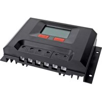
4. Overview
Refer to the illustrations on page 2 of this manual.
| 1 | terminals solar panel |
| 2 | terminals battery |
| 3 | terminals load |
| 4 | USB output |
| 5 | mounting holes |
| 6 | setting button |
| 7 | battery status LEDs |
| 8 | load status LED |
| 9 | charging LED |
5. Wiring
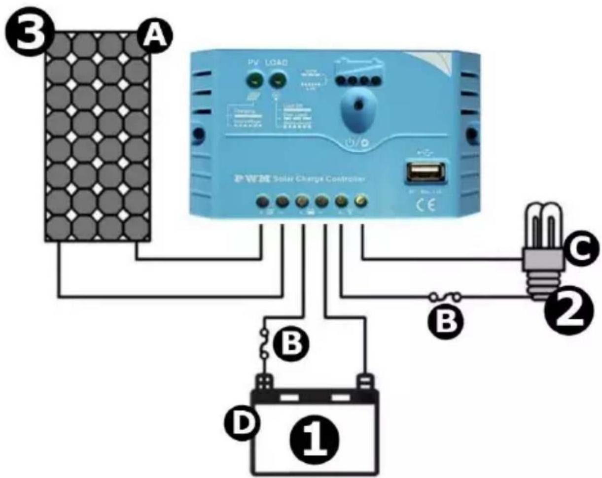
text_image
3 A PV LOAD PWM Solar Charge Controller CE B B C 2 D 1| A | photovoltaic panel |
| B | fuse |
| C | load |
| D | battery |
Connect the components to the charge regulator in the sequence shown as above. Pay attention to the positive and negative poles.
- Connect the battery first. Check if the battery indicator turns green. If not, refer to chapter Troubleshooting.
- Next, connect the load, e.g. a lamp. The load should be DC applicant with the same rated voltage as the battery's.
- Finally, connect the solar panel.
V. 01 - 27/03/2017 5 ©Velleman nv
6. Operation
6.1 Charging and Load Status LEDs
| LED | Status | System | Remark |
| charging | on | charging | normal |
| fast flashing | over-voltage | see chapter Troubleshooting | |
| load status | on | on | normal |
| off | off | ||
| slowly flashing | overload | when load amp is 1.25x rated current for 60s, or load amp is 1.5x rated current for 5s | |
| fast flashing | short-circuit | see chapter Troubleshooting |
6.2 Charging and Load Status LEDs
The parameters in the table below are for a 12 VDC system @ 25 °C. For a 24 VDC system, please double the parameters.
Battery LED status
| LED1 | LED2 | LED3 | LED4 | Status |
| slowly flashing | X | X | X | under voltage |
| fast flashing | X | X | X | over-discharged |
Battery LED status during voltage up
| ● | ● | X | X | 12.8V |
| ● | ● | ● | X | 13.4V |
| ● | ● | ● | ● | 14.1V |
Battery LED status during voltage down
| ● | ● | ● | X | 12.8V |
| ● | ● | X | X | 12.4V |
| ● | X | X | X | U_bat <12.4V |
$$ \bullet = \text { LED on } $$
$$ X = \text { LED off } $$
$$ U _ {b a t} = \text { battery voltage } $$
7. Setting
7.1 Load Work Mode
When the regulator is switched on, press the setting button to control the load output.
Note that the USB output is switched on only when the regulator is switched on.
7.2 Battery Type Setting
Hold the setting button pressed for 5 seconds. The battery status LEDs (LEDs 1 to 3, from left to right) will be flashing correspondingly. Next, press the setting button to select the battery type. The setting is confirmed when the LEDs stop flashing.
Battery type
| LED1 | LED2 | LED3 | Battery type |
| ● | X | X | sealed lead-acid |
| ● | ● | X | gel |
| ● | ● | ● | flooded |
- = LED on
X = LED off
8. Troubleshooting
- The solar panel is exposed properly to sunshine but the charging LED is off.
- The input voltage of the solar panel is lower than the battery voltage. Check the input voltage of the solar panel.
- The battery voltage is lower than 6 V. The minimum start-up voltage is 6 V.
○ Disconnected wiring. Check if the wiring is connected properly.
- The charging LED is flashing rapidly.
○ Battery voltage exceeds the overvoltage disconnect (OVD) values.
Disconnect the solar panel and check the battery voltage.
• LED1 is flashing slowly/rapidly.
○ Battery voltage too low/discharged. Check the battery voltage.
- The load status LED is flashing slowly.
- Overload. Reduce the load and press the setting button once.
- The load status LED is flashing rapidly.
○ Short-circuit. The regulator automatically resumes after 10 seconds. When a second short-circuit occurs, press the setting button once.
9. Cleaning and Maintenance
Occasionally wipe with a damp cloth to keep it looking new. Do not use harsh chemicals, cleaning solvents or strong detergents.
10. Technical Specifications
nominal system voltage 12/24 VDC
max. battery voltage to the controller 32 V
rated battery current 10 A
charge circuit voltage drop .... ≤ 0.26 V
discharge circuit voltage drop .... ≤ 0.15 V
self-consumption .... ≤ 6 mA
temperature compensation....-5 mV / °C / 2 V
operating temperature....-35 °C to +55 °C
storage temperature.... -35 °C to +80 °C
humidity .... ≤ 95%, non-condensing
USB-port 5 VDC, max. 1.2 A
IP rating IP20
terminal 4 mm ^2
dimensions 120.3 x 67 x 21.8 mm
mounting hole diameter 4.5 mm
weight....102 g
Use this device with original accessories only. Velleman nv cannot be held responsible in the event of damage or injury resulting from (incorrect) use of this device. For more info concerning this product and the latest version of this manual, please visit our website www.velleman.eu. The information in this manual is subject to change without prior notice.
© COPYRIGHT NOTICE
The copyright to this manual is owned by Velleman nv. All worldwide rights reserved. No part of this manual may be copied, reproduced, translated or reduced to any electronic medium or otherwise without the prior written consent of the copyright holder.
HANDLEIDING
1. Inleiding
| ● | ● | X | X | 12.8V |
| ● | ● | ● | X | 13.4V |
| ● | ● | ● | ● | 14.1V |
| ● | ● | ● | X | 12.8V |
| ● | ● | X | X | 12.4V |
| ● | X | X | X | U_bat < 12.4V |
- = led aan
X = led uit
U_bat =
V. 01 - 27/03/2017 13 ©Velleman nv
batterijspanning
7. Instelling
7.1 Belastingsmodus
| ● | ● | X | X | 12.8V |
| ● | ● | ● | X | 13.4V |
| ● | ● | ● | ● | 14.1V |
| ● | ● | ● | X | 12.8V |
| ● | ● | X | X | 12.4V |
| ● | X | X | X | U_bat < 12.4V |
- = LED allumée
X = LED éteinte
port USB 5 VCC, max. 1.2 A
indice IP IP20
connexion 4 mm ^2
dimensions 120.3 x 67 x 21.8 mm
| ● | ● | X | X | 12.8V |
| ● | ● | ● | X | 13.4V |
| ● | ● | ● | ● | 14.1V |
| ● | ● | ● | X | 12.8V |
| ● | ● | X | X | 12.4V |
| ● | X | X | X | U_bat < 12.4V |
- = LED encendido
X = LED apagado
| ● | ● | X | X | 12.8V |
| ● | ● | ● | X | 13.4V |
| ● | ● | ● | ● | 14.1V |
| ● | ● | ● | X | 12.8V |
| ● | ● | X | X | 12.4V |
| ● | X | X | X | U_bat <12.4V |
| ● | ● | X | X | 12,8V |
| ● | ● | ● | X | 13,4V |
| ● | ● | ● | ● | 14,1V |
| ● | ● | ● | X | 12,8V |
| ● | ● | X | X | 12,4V |
| ● | X | X | X | U_bat < 12,4V |
- = dioda LED
X = dioda LED
| ● | ● | X | X | 12.8V |
| ● | ● | ● | X | 13.4V |
| ● | ● | ● | ● | 14.1V |
| ● | ● | ● | X | 12.8V |
| ● | ● | X | X | 12.4V |
| ● | X | X | X | U_bat < 12.4V |
- = LED ligado
X = LED desligado
Velleman® Service and Quality Warranty
Since its foundation in 1972, Velleman® acquired extensive experience in the electronics world and currently distributes its products in over 85 countries.
All our products fulfil strict quality requirements and legal stipulations in the EU. In order to ensure the quality, our products regularly go through an extra quality check, both by an internal quality department and by specialized external organisations. If, all precautionary measures notwithstanding, problems should occur, please make appeal to our warranty (see guarantee conditions).
General Warranty Conditions Concerning Consumer Products (for EU):
- All consumer products are subject to a 24-month warranty on production flaws and defective material as from the original date of purchase.
- Velleman® can decide to replace an article with an equivalent article, or to refund the retail value totally or partially when the complaint is valid and a free repair or replacement of the article is impossible, or if the expenses are out of proportion.
You will be delivered a replacing article or a refund at the value of 100% of the purchase price in case of a flaw occurred in the first year after the date of purchase and delivery, or a replacing article at 50% of the purchase price or a refund at the value of 50% of the retail value in case of a flaw occurred in the second year after the date of purchase and delivery.
- Not covered by warranty:
- all direct or indirect damage caused after delivery to the article (e.g. by oxidation, shocks, falls, dust, dirt, humidity...), and by the article, as well as its contents (e.g. data loss), compensation for loss of profits;
- consumable goods, parts or accessories that are subject to an aging process during normal use, such as batteries (rechargeable, non-rechargeable, built-in or replaceable), lamps, rubber parts, drive belts... (unlimited list);
- flaws resulting from fire, water damage, lightning, accident, natural disaster, etc....;
- flaws caused deliberately, negligently or resulting from improper handling, negligent maintenance, abusive use or use contrary to the manufacturer's instructions;
- damage caused by a commercial, professional or collective use of the article (the warranty validity will be reduced to six (6) months when the article is used professionally);
- damage resulting from an inappropriate packing and shipping of the article;
- all damage caused by modification, repair or alteration performed by a third party without written permission by Velleman®.
- Articles to be repaired must be delivered to your Velleman® dealer, solidly packed (preferably in the original packaging), and be completed with the original receipt of purchase and a clear flaw description.
- Hint: In order to save on cost and time, please reread the manual and check if the flaw is caused by obvious causes prior to presenting the article for repair. Note that returning a non-defective article can also involve handling costs.
- Repairs occurring after warranty expiration are subject to shipping costs.
- The above conditions are without prejudice to all commercial warranties.