FX-KM196 - Sweeper Fuxtec - Free user manual and instructions
Find the device manual for free FX-KM196 Fuxtec in PDF.
| Product type | 3-in-1 thermal sweeper |
| Brand | Fuxtec |
| Model | FX-KM196 |
| Engine | Loncin G200F |
| Displacement | 196 cm³ |
| Power | 4.1 kW at 3600 rpm |
| Fuel | Unleaded gasoline |
| Fuel tank capacity | 3.6 L |
| Oil tank capacity | 0.6 L (SAE 10W-30) |
| Transmission | 5 forward gears, 2 reverse gears |
| Working width | 600 mm |
| Brush diameter | 345 mm |
| Brush alignment | +/- 15° |
| Wheel diameter | 13 inches |
| Net weight | 62 kg |
| Gross weight | 70 kg |
| Accessory change | Tool-free |
| Warranty | 24 months (private use) |
| Intended use | Cleaning streets, driveways, well-ventilated storage areas |
Frequently Asked Questions - FX-KM196 Fuxtec
User questions about FX-KM196 Fuxtec
0 question about this device. Answer the ones you know or ask your own.
Ask a new question about this device
Download the instructions for your Sweeper in PDF format for free! Find your manual FX-KM196 - Fuxtec and take your electronic device back in hand. On this page are published all the documents necessary for the use of your device. FX-KM196 by Fuxtec.
USER MANUAL FX-KM196 Fuxtec
natural_image
Illustration of a snowman with three views of its blade and chassis against a black background (no text or symbols)WARNING: Before starting work, please read the operating manual carefully, as it contains all the important information and safety instructions that must be followed in order to use this equipment properly.
natural_image
Orange Rutherford utility saw with clear blade and mounted components (no visible text or symbols)Benzin-Kehrmaschine FX-KM196
text_image
1 A B C D F G E H I M L K Jnatural_image
Mechanical assembly diagram showing two configurations of a linkage mechanism with no visible text or symbolsnatural_image
Abstract black graphic with curved shape and two vertical lines, no text or symbols presentnatural_image
Technical line drawing of a mechanical device with an arrow indicating motion (no text or symbols)natural_image
Technical line drawing of a mechanical assembly with two components, one showing internal gear-like structure and the other a circular housing (no text or symbols)- Original user manual 26
- General Safety Precautions.... 27
- Hazard symbols and meanings 30
- Main Components ...... 31
- Assembly.... 33
- Engine Operations.... 34
- Operation 36
- During Use.... 39
- Change Attachments ...... 40
- Storage 43
- Troubleshooting 43
- Maintenance.... 44
- Declaration of Conformity 45
1. Original user manual
Please read this entire manual before operating the equipment. It instructs you how to safely and efficiently set up, use and maintain your device. Please be sure that you, and any other persons who will operate the machine, carefully follow the recommended safety practices at all times. Failure to do so could result in personal injury or property damage.
Function of Sweeper
This sweeper is designed solely for the use in clean up, maintenance and similar. And please pay more attention that NOT for small stone cleaning, to avoid the injury.
Use in any other way is considered contrary to the intended use. Compliance with and strict adherence to operation, service and repair conditions, as specified by the manufacturer, are also essential elements of the intended use.
Terms used in Manual
Right-hand, left-hand, front and rear are determined from the actual operating position.
SAFETY STATEMENTS
DANGER
THIS STATEMENT IS USED WHERE SERIOUS INJURY OR DEATH WILL RESULT IF THE INSTRUCTIONS ARE NOT FOLLOWED PROPERLY.
WARNING
THIS STATEMENT IS USED WHERE SERIOUS INJURY OR DEATH COULD RESULT IF THE INSTRUCTIONS ARE NOT FOLLOWED PROPERLY.
CAUTION
THIS STATEMENT IS USED WHERE MINOR INJURY COULD RESULT IF THE INSTRUCTIONS ARE NOT FOLLOWED PROPERLY.
NOTICE
THIS STATEMENT IS USED WHERE EQUIPMENT OR PROPERTY DAMAGE COULD RESULT IF THE INSTRUCTIONS ARE NOT FOLLOWED PROPERLY.
THIS SYMBOL BY ITSELF OR USED WITH A SAFETY SIGNAL WORD THROUGHOUT THIS MANUAL IS USED TO CALL YOUR ATTENTION TO INSTRUCTIONS INVOLVING YOUR PERSONAL SAFETY OR THE SAFETY OF OTHERS. FAILURE TO FOLLOW THESE INSTRUCTIONS CAN RESULT IN INJURY OR DEATH.
2. General Safety Precautions
WARNING

READ MANUAL PRIOR TO INSTALL
Improper installation, operation, or maintenance of this equipment could result in severe injury or death. Operators and maintenance personnel should read this manual as well as all manuals related to this equipment and the prime mover thoroughly before beginning installation, operation, or maintenance. Follow all Safety instructions in This manual and the prime Movers manual.
WARNING

READ AND UNDERSTAND ALL SAFETY STATEMENTS
Read all safety decals and safety statements in all manuals prior to operating or working on this equipment. Know and obey all regulations, local laws and other professional guidelines for your operation. Know and follow acceptable work practices when assembling, maintaining, repairing, mounting, removing or operating this equipment.
WARNING

KNOW YOUR EQUIPMENT
Know your equipment's capabilities, dimensions and operations before operating. Visually inspect your equipment before you start, and never use equipment that is not in proper working order with all safety devices intact. Check all hardware to assure it is tight. Make sure that all locking pins, latches, and connected devices are correctly installed and secured. Remove and replace any damaged, tired or excessively worn parts. Make sure all safety decals are in place and are legible. Keep decals clean, and replace them if they become dull and hard to read.
WARNING

PROTECT AGAINST FLYING DEBRIS
Always wear proper safety glasses, goggles or a face shield when driving pins in or out or when operation causes dust, flying debris, or any other hazardous material.
WARNING

LOWER OR SUPPORT RAISED EQUIPMENT
Do not work under raised booms without supporting them. Do not use support material made of concrete blocks, logs, buckets, barrels or any other material that could suddenly collapse or shift positions. Make sure support material is solid, not decayed, warped, twisted, or tapered. Lower booms to ground level or onto blocks. Lower booms and attachments to the ground before leaving the cab or operator's station.
WARNING

DO NOT MODIFY MACHINE OR ATTACHMENTS
Modifications may weaken the integrity of the attachment. They may impair the function, safety, life and performance of the attachment, when making repairs, use only the manufacturer's genuine parts, following authorised instructions. Other parts may be substandard in fit and quality. Never modify any RoPS (Rollover Protection System) equipment or device. Any modifications must be authorised in writing by the manufacturer.
WARNING

SAFELY MAINTAIN AND REPAIR EQUIPMENT
- Do not wear loose clothing or any accessories that can catch in moving parts. If you have long hair, cover or secure it so that it does not become entangled in the equipment.
• Work on a level surface in a well-lit area. - Use properly grounded electrical outlets and tools.
- Use the correct tool for the job at hand. Make sure they are in good condition for the task required.
- Wear the protective clothing equipment specified by the tool manufacturer.
WARNING

SAFELY OPERATE EQUIPMENT
Do not operate equipment until you are thoroughly trained by a qualified operator in how to use the controls; know its capabilities, dimensions, and all safety requirements. See your prime movers manual for these instructions.
- keep all step plates, grab bars, pedals, and controls free of dirt, grease, debris, and oil.
- Never allow anyone to be around the equipment when it is operating.
- Do not allow riders on the attachment or the prime mover.
- Do not operate the equipment from anywhere other than the correct operator's position.
- Never leave equipment unattended with the engine running or with this attachment in a raised position.
- Do not alter or remove any safety feature from the prime mover or this attachment.
- know your worksite safety rules as well as traffic rules and flow. When in doubt on any safety issue, contact your supervisor or safety coordinator for an explanation.
WARNING

FALL HAZARD DO NOT OPERATE NEAR UNGUARDED EDGES.
- This sweeper is NOT intended for rooftop use.
- When operating sweeper, adhere to all government rules, local laws and other professional guidelines for your sweeping application.
3. Hazard symbols and meanings

WARNING!

text_image
Warning symbol and open book icon with exclamation mark and information symbolWARNING! Read the instructions before operating the machine.
DANGER! Ejected objects. Do not turn the brush towards onlookers or animals.
natural_image
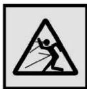
Two human figures with a small plow and a tractor, no text or symbols presentDANGER! Keep people, children and animals away from the work area.

DANGER! Keep hands and feet away from rotating parts.

DANGER! Always use hearing protectors. Wear eye protection.

DANGER! Risk of fire or explosion. Do not smoke; do not use open flames or ignition.
IMPORTANT
Any damaged or illegible decals should be replaced. Please order replacement decals from an authorised assistance centre of FUXTEC.
4. Main Components
text_image
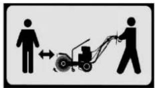
1 A B C D F G E H I M L K JA. Brush control lever
B. Drive control lever
C. Dashboard
D. Gear Position
E. Brush direction
F. Unlock control lever
G. Engine
H. Brush safety guard
I. Brush
J. Fixing accessories equipment
K. Caster wheels
L. Transmission box
M. Wheel
PACKAGE CONTENTS
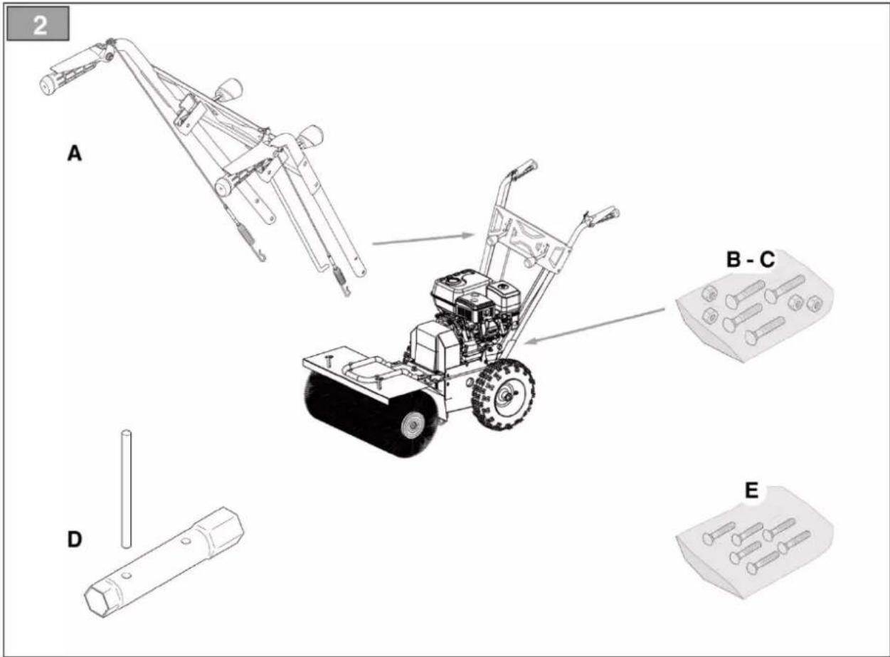
text_image
2 A B - C D E| Pos. | Description | Qty |
| A | Handle with pre-installed rods and wires | 1 |
| B | Handle fastening screws | 4 |
| C | Handle fastening bolts | 4 |
| D | Spark plug removal key | 1 |
| E | Nuts and bolts | 1 |
NOTES:
- Cautiously open the packaging, paying attention not to loose components.
- Consult the documentation in the box, including these instructions.
- Remove all the unassembled parts from the box.
- Remove the machine from the box.
- Dispose of the box and packaging in compliance with local regulations.
5. Assembly
Please note that during assembly, maybe you'll need a helper!
Forward and brush control cable assembly
Couple the cable eyelet to the specific opening (fig. 3).
NOTE: The cables are already pre-assembled on the dashboard.
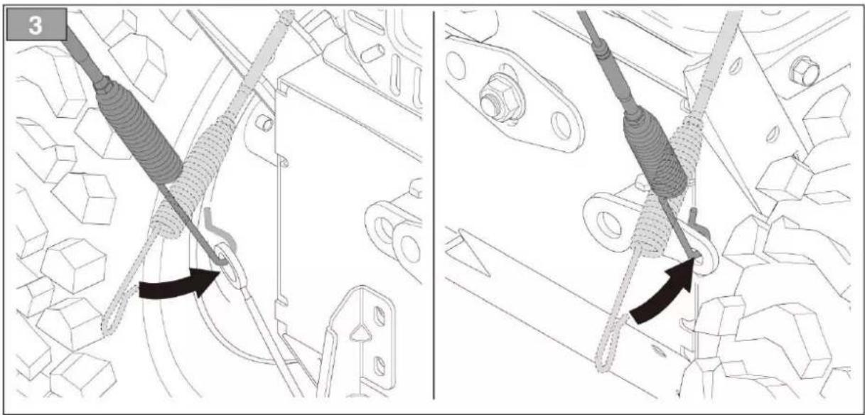
natural_image
Technical diagram showing two mechanical assembly steps with coiled springs and a hook, no text or symbols present1. Handle assembly
The handle is delivered with the dashboard already assembled. The device handle assembly screws, gear control fastening screws and nuts and bolts to secure the directional brush control are provided in a separate package found in the machine packaging. Install as follows:
a) Bring the two tubes at the ends of the handle (fig. 4.A) up to the support (fig. 4.B).
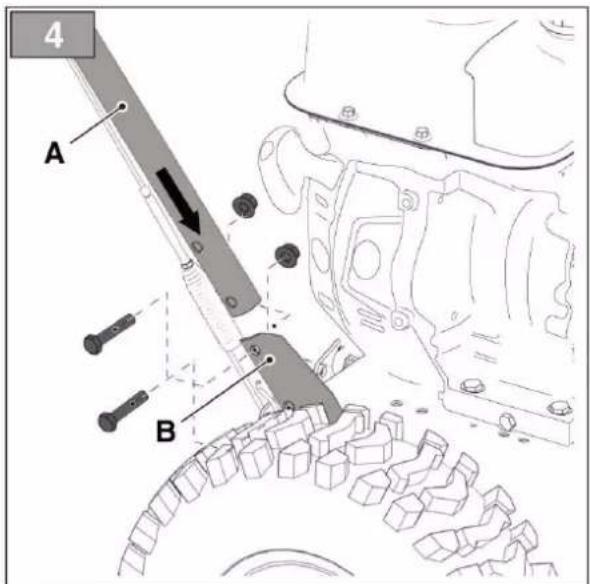
text_image
4 A Bb) Insert the screws in the holes and secure in place with the nuts.
2. Installation of the gear control
a. Remove the previously assembled articulated joint (fig. 5.A) on the washer gear control (fig. 5.B) and nut (fig. 5.C). b. Insert the articulated joint (fig. 5.A) of the gear control in the hole on the lever (fig. 5.D) to connect it to the transmission.
c. Secure the washer (fig. 5.B) and nut (fig. 5.C).
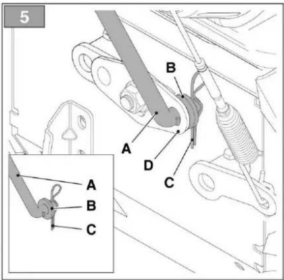
text_image
5 A B C D A B C3. Brush directional control assembly
d. Remove the previously assembled articulated joint (fig. 6.A) on the brush directional control nut (fig. 6.B).
e. Insert the articulated joint (fig. 6.A) on the directional brush control in the lever hole (fig. 6.C) to connect it to the drive.
f. Secure the nut (fig. 6.B).
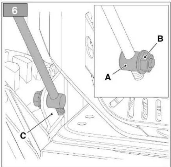
text_image
6 C A B6. Engine Operations
NOTICE: THE ENGINE IS DELIVERED WITHOUT OIL AND GASOLINE.
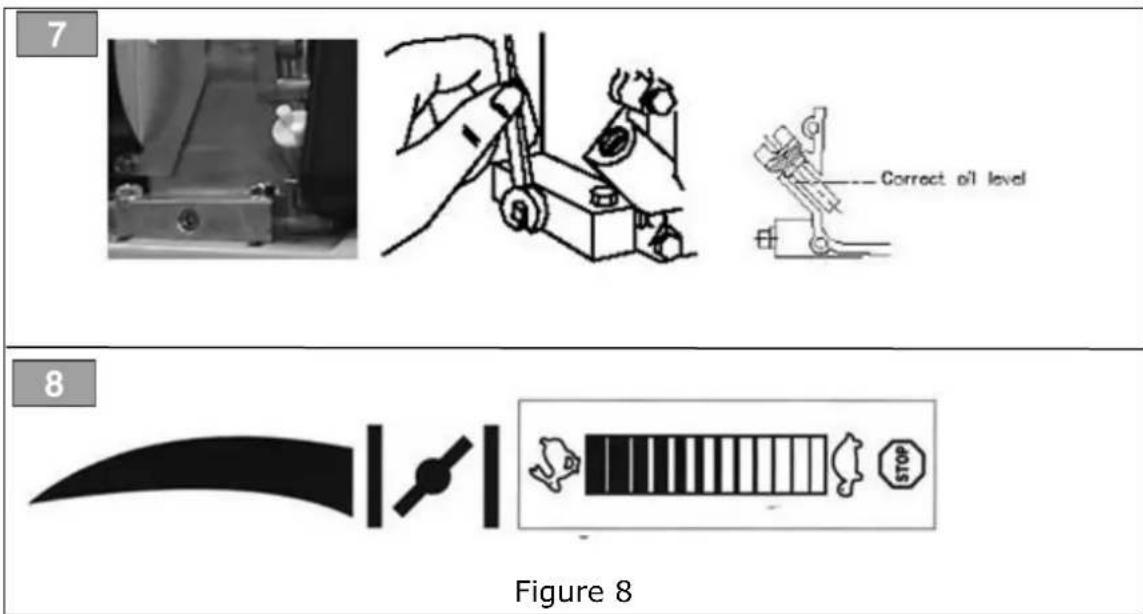
Oil Filling:
Place the engine in a horizontal position. Remove the plug and fill with oil right to the edge. (Figure 7)
Fuel
Use lowest available octane unleaded fuel. When filling, place the machine in a horizontal position. Always replace old fuel. Always stop the engine when fueling. Never fill up with fuel on a hot engine. Never use gasoline mixed with oil.
Operation - Start and Stop
Cold Engine
Activate the engine choke. Set the throttle control on full speed. (Figure 8)
First pull the starting rope a couple of times, shortly, until it feels tight. Pull the starting rope slowly to the point where it feels tight, place your left hand on the engine in order to hold back, and pull the starting rope hard once. When the engine runs, deactivate the choke.
NOTICE: NEVER LET THE STARTING ROPE WIND AGAIN BY ITSELF.
Follow it all the way back with your hand. If the engine does not run in spite of several attempts, this may be caused by the fact that there is too much fuel in the cylinder/carburettor, and that the spark plug has become moist. Remove the plug and wipe it off.
Stop the Engine:
Set the throttle control in position "Stop". Set the throttle lever to idle and let the engine run for 12-20 seconds before the lever is moved to stop. Never leave the sweeper without stopping the engine.
NOTICE: Do not turn off the engine by switching on the choke, as this may result in damage to the engine.
text_image
7 Correct oil level 8 Figure 87. Operation
CAUTION!
A SWEEPER IS A DEMANDING MACHINE.
Only fully trained operators or trainee operators under the supervision of a fully qualified person should use this machine.
Before operating sweeper:
- Operate sweeper controls in an off-road location.
- Be sure that you are in a safe area, away from traffic or other hazards.
- Check all hardware making sure it is tight.
- Replace any damaged or tired hardware with properly rated fasteners.
- Check tire pressure before sweeping.
- Remove from the sweeping area all property that could be damaged by flying debris.
- Be sure all persons not operating the sweeper are clear of the sweeper discharge area for protection, and wear a dust mask.
- Always wear proper apparel such as a long-sleeved shirt buttoned at the cuffs; safety glasses goggles or a face shield; ear protection; and a dust mask.
While operating sweeper
DANGER

FALL HAZARD DO NOT OPERATE NEAR UNGUARDED EDGES.
- This sweeper is not intended for rooftop use.
- When operating sweeper, adhere to all government rules, local laws and other professional guidelines for your sweeping application.
- Minimise flying debris - use the slowest rotating speed that will do the job.
- Keep hands, feet, hair and other loose clothing away from all moving parts.
- Before leaving the operator's position for any reason stop engine.
NOTICE: AVOID TRANSMISSION DAMAGE. Do not shift while in motion.
WARNING

Leave the brush hood (shield) and all other shields and safety equipment in place when operating the sweeper.
- When sweeping on rough terrain, reduce speed to avoid "bouncing" the sweeper. Loss of control can result.
- Never sweep toward people, buildings, vehicles or other objects that can be damaged by flying debris.
- Only operate the controls while the engine is running.
- While you operate the sweeper slowly in an open area, check for proper operation of all controls and all protective devices. Note any repairs needed during the operation of the sweeper. Report any needed repairs.
Before each use
Perform daily maintenance as indicated in Maintenance Schedule.
Run the sweeper at a low idle, check for proper brush rotation and drive engagement.
WARNING

AVOID SERIOUS INJURY.
Check for large objects that could harm the operator or others if thrown by the sweeper. Remove these items before operating.
During use
Directing Debris
- Avoid excessive downward pressure on the brush sections to prevent excessive wear. A two- to a four-inch-wide pattern is sufficient for most applications.
- Direct debris by angling the brush head in that direction.
- Observe wind direction. Sweeping with the wind makes sweeping more effective and helps keep debris off the operator.
- The terms swing, and angle is used interchangeably.
Brush Direction
The brush direction is regulated by a lever (fig. 9B) that tilts it in the required direction. Move the lever forward or rear in one of the three available positions to tilt the brush.
- Lever forward = 15^ to the right.
- Lever central = 0^ no tilt.
- Lever rear = 15^ to the left.
Sweeping
To sweep:
- Turn the directional brush control (fig. 9 B) to the required position. (See Brush Direction)
- Set the gear depending on the route and the amount of material to be swept.
- Engage the brush drive. (fig. 9C)
- Engage the traction drive. (fig. 9D)
NOTICE: AVOID SWEEPER DAMAGE.
Reduce travel speed to avoid hitting immovable objects.
The sweeper is equipped with an instant shut off when you release the levers, the brush and machine stop.
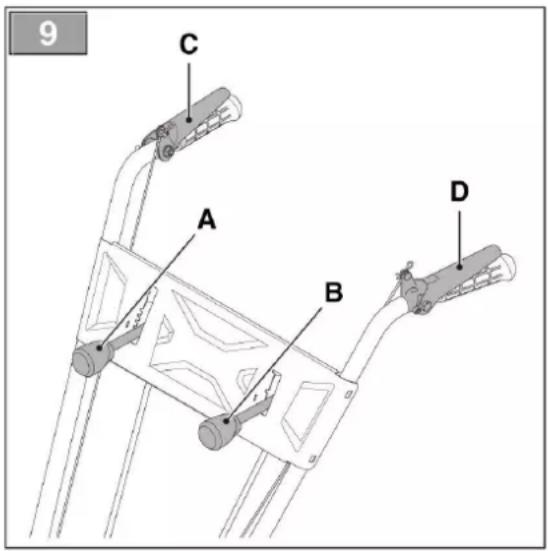
text_image
9 C A B DOperating Tips
NOTICE: AVOID SWEEPER DAMAGE. Do not ram into piles.
Large Areas
- For uneven or dirt surfaces, reduce speed to avoid jogging the brush and damaging it.
- Sweep creating a central passage dividing the area into two parts and then sweeping the remaining areas. That reduces the load on the brush.
8. During Use
Snow

- Snow is removed more quickly when it is still fresh - passback over the already cleared zones to remove snow residue.
- If possible, clear the snow in the direction of the wind. Check the distance and the direction of the removed snow.
- Reduce the engine rotations before stopping it.
Dirt & Gravel
- To reduce the amount of duct lifted when sweeping, work at low brush speed. If possible, also work on damp or cloudy days or after it rains.
- For gravel, adjust the height of the brush to avoid throwing them and causing potential damages.
Heavy Debris
- Reduce forward speed and work without using the entire machine working width.
WARNING
SAFELY OPERATE EQUIPMENT
Do not operate equipment until you are thoroughly trained by a qualified operator in how to use the controls; know its capabilities, dimensions, and all safety requirements. See your prime movers manual for these instructions.
- Keep all step plates, grab bars, pedals, and controls free of dirt, grease, debris, and oil.
- Never allow anyone to be around the equipment when it is operating.
- Do not allow riders on the attachment or the prime mover.
- Do not operate the equipment from anywhere other than the correct operator's position.
- Never leave equipment unattended with the engine running or with this attachment in a raised position.
- Do not alter or remove any safety feature from the prime mover or this attachment.
- Know your worksite safety rules as well as traffic rules and flow. When in doubt on any safety issue, contact your supervisor or safety coordinator for an explanation.
WARNING
IN AN EMERGENCY, RELEASE LEVERS AS QUICKLY AS POSSIBLE AND STOP THE ENGINE.
Height adjustment of Caster Wheels & Brushes
Once the brushes get worn, it is necessary to adjust the height of the brushes, i.e. how close they are to the surface to sweep. This adjustment takes place by moving the plastic rings of the brush caster wheels. See as
follows:
- Loosen the side knob (fig. 10.A);
- Rotate the upper knob (fig. 10.B) in clockwise / anticlockwise to lift / lower the small wheels;
- Fix the side knob (fig. 10.A);
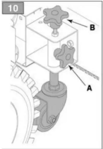
text_image
10 B A9. Change Attachments
If what you bought is multi-function sweeper &snow thrower, you should change the function by yourself. Please check below steps for success assembly work.
To Separate Engine part and Attachments (Sweeper / Snow thrower head)
- If the attachment on the machine is sweeper, please do following first:
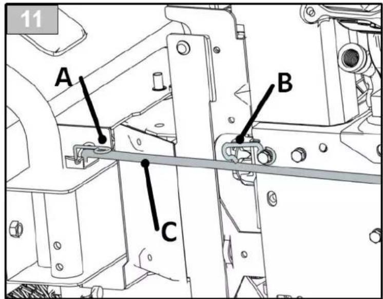
a) Pull the hook (fig.11 A) upward to release the direction bar;
b) Pull the direction bar (fig.11 C) out from the hole.
c) Click the direction bar (fig.11 C) into hook (fig.11 B) to avoid its moving.
If the attachment on the machine is snow thrower, please skip this step.
text_image
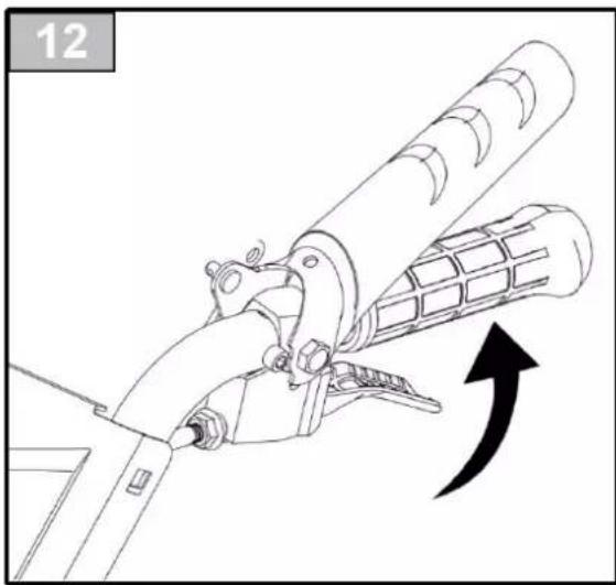
11 A B C- Grasp the red lock control lever under left handle. Raise up the engine part to release attachment.
natural_image
Technical line drawing of a mechanical device with an arrow indicating motion (no text or symbols)To Connect Engine part with Attachments (Sweeper / Snow thrower head)
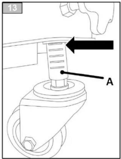
- Put the sweeper / snow thrower head on an open area.
- If you are going to connect sweeper head, please make sure that both caster wheels (fig.13 A) are in the fifth groove.
text_image
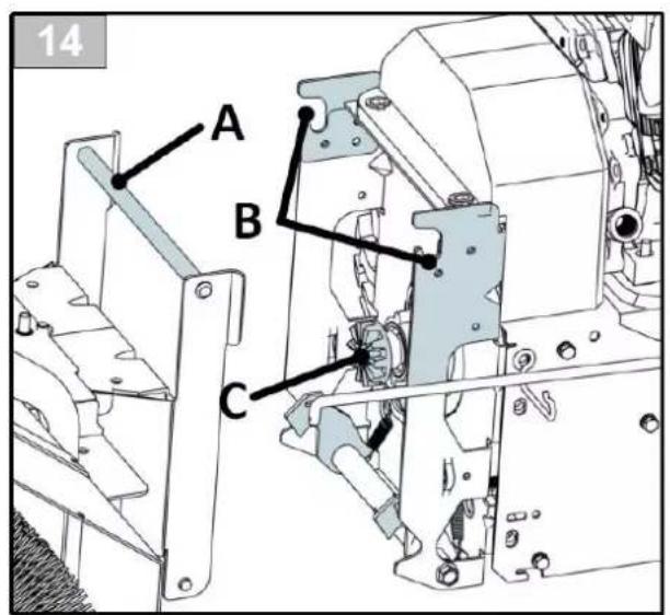
13 A- Hold the handle of the engine part, and move it towards the attachment.
- Lower the engine part to make the bar (fig.14 A) go into the two hooks (fig.14 B) to interlock gears of two parts (fig. 14C) as shown in fig. 15.
Please note that during this period, do not grasp the red lock control lever as shown in fig. 12.
text_image
14 A B C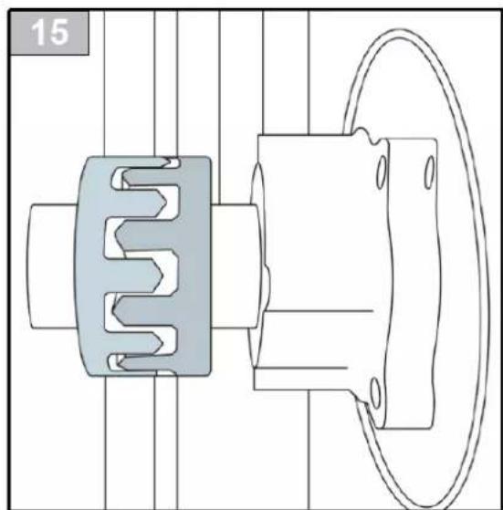
natural_image
Technical line drawing of a mechanical assembly with two components, one showing internal gear-like structure and the other a circular housing (no text or symbols)- If you are connecting snow thrower head, it's OK for working now.
- If you are connecting sweeper head, you have to continue the following steps:
a) Remove the direction bar (fig.11 C) from the hook (fig.11 B).
b) Press the direction bar (fig.11 C) to the hole on the sweeper head.
c) Press down the hook (fig.11 A) to fix the direction bar (fig.11 C).
Then your sweeper is workable now.
10. Storage
NOTICE:
- Do not store the sweeper with weight on the brush. Weight will deform the bristles, destroying the sweeping effectiveness.
- Do not store polypropylene brushes in direct sunlight. The material can deteriorate and crumble before the bristles are worn out.
- Keep polypropylene brush material away from intense heat or flame.
11. Troubleshooting
| The engine does not start | Ensure that the spark plug is not defective |
| Ensure that the spark plug cap is fitted correctly | |
| The engine runs irregularly | Ensure that the choke is deactivated |
| Ensure that there are no impurities in the fuel | |
| The brushes will not rotate | Check whether the belt coupling is adjusted correctly. |
| Check whether the v-belt is defective | |
| The machine will not run | Make sure that the belt coupling is adjusted correctly |
| The machine does not sweep effectively | Check whether the v-belt is defective |
| Check whether the brush distance to the surface is set correctly |
12. Maintenance
MAINTENANCE SCHEDULE
| PROCEDURES | BEFORE EACH USE | 25 HOURS | 100 HOURS | AFTER EACH USE |
| Hardware - Inspect & tighten |  | |||
| Engine & Air Filter - check & clean if necessary |  | |||
| Oil, engine - check the level |  | |||
| Wash Unit - Remove Grease & Debris | [DRCW] |
Maintenance
If you need to change the belts, please contact the distributor or local agent. Do not change them by yourself.

Residual risks
Even when the machine is used as prescribed, it is not possible to eliminate all residual risk factors. The following hazards may arise in connection with the power tool's construction and design:
- Damage to the lungs if an effective dust mask is not worn.
- Damage to hearing if adequate hearing protection is not worn.
- Damages to health resulting from vibration emission if the power tool is being used over a more extended period or not adequately managed and properly maintained.
WARNING
This machine produces an electromagnetic field during operation. This field may, under some circumstances interfere with active or passive medical implants. To reduce the risk of severe or fatal injury, we recommend persons with medical implants to consult their physician and the medical implant manufacturer before operating this machin
13. Declaration of Conformity
In the following the
FUXTEC GmbH
KAPPSTRASSE 69, 71083 HERRENBERG-GULTSTEIN Germany declares that the product
3in1 Benzin-Kehrmaschine FX-KM196 (Schneefräse optional), to which this declaration refers, meets the relevant essential health and safety requirements of the applicable EC Directives 2006/42 / EC. This statement applies only to the machine in the condition in which it was placed on the market, parts subsequently installed by the end-user and/or subsequent interventions are disregarded.
Applied harmonized standards: EN 13019: 2001+A1:2008
EN ISO 12100
EN ISO 13732-1, EN982, EN983
Measured sound power level LpA 87.8 dB(A), K=3 dB(A)
Guaranteed sound power level LwA 101.56dB(A)
Herrenberg, 24th of May 2022
Leonhard Zirkler
(Managing Director)

text_image
C. JilleManufacturer:
FUXTEC GmbH
KAPPSTRASSE 69, 71083 HERRENBERG Germany
Place of technical documentation:
FUXTEC GmbH, KAPPSTRASSE 69, 71083 HERRENBERG Germany
L. Zirkler, Managing Director
FUXTEC
natural_image
Product photo of an orange snowplow tractor with visible blade and side brackets (no text or symbols)natural_image
Orange RATEN grassblower with clear blade and mounted engine (no visible text or symbols)text_image
1 A B C D F G E H I M L K Jnatural_image
Technical diagram showing two mechanical assembly steps with coiled springs and connectors (no text or symbols)natural_image
Abstract black graphic with curved shape and two vertical lines (no text or symbols)text_image
Warning sign with striped bar, stop button, and animal iconsnatural_image
Technical line drawing of a mechanical device with an arrow indicating motion (no text or symbols)natural_image
Technical line drawing of a mechanical assembly with gear and housing components (no text or symbols)L. Zirkler, Direction