Soundweb Contrio EC-4BV - Controller BSS Audio - Free user manual and instructions
Find the device manual for free Soundweb Contrio EC-4BV BSS Audio in PDF.

| Product Type | Network Audio Controller |
| Brand | BSS Audio |
| Model | Soundweb Contrio EC-4BV |
| Power Supply | PoE (Power over Ethernet) 44-57 VDC, 13 W |
| Connectivity | Ethernet RJ45 for PoE and audio |
| Electromagnetic Compatibility | Compliant with FCC Part 15 and EN 55022/55024 standards |
| Usage | Indoor only |
| Maximum altitude | 2000 m |
| Cleaning | Dry cloth only |
| Maintenance | No user-serviceable parts. Refer all servicing to qualified personnel. |
| Safety | Disconnect during thunderstorms. Do not use near water. Plug into a grounded outlet. |
| Recommended cables | VW-1 rated, RJ45 Ethernet cables for PoE and shielded cables for signals |
| Replacement fuse | 13 A, ASTA BS1362 approved |
| Operating temperature | Not specified (standard indoor use) |
| Humidity | Not specified (avoid humidity) |
| Weight | Not specified (estimated < 1 kg) |
| Dimensions | Not specified (compact wall-mount type) |
Frequently Asked Questions - Soundweb Contrio EC-4BV BSS Audio
User questions about Soundweb Contrio EC-4BV BSS Audio
0 question about this device. Answer the ones you know or ask your own.
Ask a new question about this device
Download the instructions for your Controller in PDF format for free! Find your manual Soundweb Contrio EC-4BV - BSS Audio and take your electronic device back in hand. On this page are published all the documents necessary for the use of your device. Soundweb Contrio EC-4BV by BSS Audio.
USER MANUAL Soundweb Contrio EC-4BV BSS Audio
soundweb CONTRIO controllers
Installation Guide
Ethernet Wall Controllers:
EC-V
EC-4B
EC-4BV
EC-8BV
IMPORTANT SAFETY INSTRUCTIONS
text_image
CAUTION MAKE OF ELECTRIC SHOCK DO NOT OPEN ATTENTION: ANOUGH BE CHINE ELECTRANUE - ME PAD-OUVAN WARNING: TO REDUCE THE RANK OF FINE OR ELECTRIC SHOCK DO NOT EXPOSED THIS EQUIPMENT TO RANK OR MOISTURE ATTENTION: POUR RESUME LE ANOUGH D'INDEPENDRE NO D'ÉLECTROCCUTION D'EXPENSE PAS GET APPAREL À LA PLATE OU LE MACHUÊTThe symbols shown above are internationally accepted symbols that warn of potential hazards with electrical products. The lightning flash with arrowpoint in an equilateral triangle means that there are dangerous voltages present within the unit. The exclamation point in an equilateral triangle indicates that it is necessary for the user to refer to the owner's manual.
These symbols warn that there are no user serviceable parts inside the unit. Do not open the unit. Do not attempt to service the unit yourself. Refer all servicing to qualified personnel. Opening the chassis for any reason will void the manufacturer's warranty. Do not get the unit wet. If liquid is spilled on the unit, shut it off immediately and take it to a dealer for service. Disconnect the unit during storms to prevent damage.
The following is indicative of low altitude use; do not use this product above 2000m.

U.K. MAINS PLUG WARNING
A molded mains plug that has been cut off from the cord is unsafe. Discard the mains plug at a suitable disposal facility.
NEVER UNDER ANY CIRCUMSTANCES SHOULD YOU INSERT A DAMAGED OR CUT MAINS PLUG INTO A 13 AMP POWER SOCKET.
Do not use the mains plug without the fuse cover in place. Replacement fuse covers can be obtained from your local retailer. Replacement fuses are 13 amps and MUST be ASTA approved to BS1362.
WARNING
Use only VW-1 rated wiring and Ethernet cables for RJ45 POE and analog connections. Equipment to be powered by certified POE power adaptor with rated output of 44–57VDC, 13W.
SAFETY INSTRUCTIONS
NOTICE FOR CUSTOMERS IF YOUR UNIT IS EQUIPPED WITH A POWER CORD.
WARNING: THIS APPLIANCE SHALL BE CONNECTED TO A MAINS SOCKET OUTLET WITH A PROTECTIVE EARTHING CONNECTION.
THE CORES IN THE MAINS LEAD ARE COLOURED IN ACCORDANCE WITH THE FOLLOWING CODE:
AS COLOURS OF THE CORES IN THE MAINS LEAD OF THIS APPLIANCE MAY NOT CORRESPOND WITH THE COLOURED MARKINGS IDENTIFYING THE TERMINALS IN YOUR PLUG, PROCEED AS FOLLOWS:
- THE CORE WHICH IS COLOURED GREEN AND YELLOW MUST BE CONNECTED TO THE TERMINAL IN THE PLUG MARKED WITH THE LETTER E, OR WITH THE EARTH SYMBOL, OR COLOURED GREEN, OR GREEN AND YELLOW.
- THE CORE WHICH IS COLOURED BLUE MUST BE CONNECTED TO THE TERMINAL MARKED N OR COLOURED BLACK.
- THE CORE WHICH IS COLOURED BROWN MUST BE CONNECTED TO THE TERMINAL MARKED L OR COLOURED RED.
THIS EQUIPMENT MAY REQUIRE THE USE OF A DIFFERENT LINE CORD, ATTACHMENT PLUG, OR BOTH, DEPENDING ON THE AVAILABLE POWER SOURCE AT INSTALLATION. IF THE ATTACHMENT PLUG NEEDS TO BE CHANGED, REFER SERVICING TO QUALIFIED SERVICE PERSONNEL WHO SHOULD REFER TO THE TABLE BELOW. THE GREEN/YELLOW WIRE SHALL BE CONNECTED DIRECTLY TO THE UNITS CHASSIS.
| CONDUCTOR | WIRE COLOR | |
| Normal Alt | ||
| L LIVE BROWN BLACK | ||
| N NEUTRAL BLUE WHITE | ||
| E EARTH GND GREEN/YEL GREEN | ||
WARNING: IF THE GROUND IS DEFEATED, CERTAIN FAULT CONDITIONS IN THE UNIT OR IN THE SYSTEM TO WHICH IT IS CONNECTED CAN RESULT IN FULL LINE VOLTAGE BETWEEN CHASSIS AND EARTH GROUND. SEVERE INJURY OR DEATH CAN THEN RESULT IF THE CHASSIS AND EARTH GROUND ARE TOUCHED SIMULTANEOUSLY.
WARNING:
• APPARATET MÅ TILKOPLES JORDET STIKKONTAKT.
• APPARATEN SKALL ANSLUTAS TILL JORDAT UTTAG.
- LAITE ON LIITETTÄVÄ SUOJAKOSKETTIMILLA VARUSTETTUUN PISTORASIAAN.
IMPORTANT SAFETY INSTRUCTIONS
WARNING FOR YOUR PROTECTION READ THE FOLLOWING:
READ THESE INSTRUCTIONS.
KEEP THESE INSTRUCTIONS.
HEED ALL WARNINGS.
FOLLOW ALL INSTRUCTIONS.
DO NOT USE THIS APPARATUS NEAR WATER.
CLEAN ONLY WITH A DRY CLOTH.
FOR INDOOR USE ONLY.
DO NOT BLOCK ANY OF THE VENTILATION OPENINGS. INSTALL IN ACCORDANCE WITH THE MANUFACTURER'S INSTRUCTIONS.
DO NOT INSTALL NEAR ANY HEAT SOURCES SUCH AS RADIATORS, HEAT REGISTERS, STOVES, OR OTHER APPARATUS (INCLUDING AMPLIFIERS) THAT PRODUCE HEAT.
ONLY USE ATTACHMENTS/ACCESSORIES SPECIFIED BY THE MANUFACTURER.
UNPLUG THIS APPARATUS DURING LIGHTNING STORMS OR WHEN UNUSED FOR LONG PERIODS OF TIME.
Do not defeat the safety purpose of the polarized or grounding-type plug. A polarized plug has two blades with one wider than the other. A grounding type plug has two blades and a third grounding prong. The wide blade or third prong are provided for your safety. If the provided plug does not fit your outlet, consult an electrician for replacement of the obsolete outlet.
Protect the power cord from being walked on or pinched particularly at plugs, convenience receptacles, and the point where they exit from the apparatus.
Use only with the cart stand, tripod bracket, or table specified by the manufacture, or sold with the apparatus. When a cart is used, use caution when moving the cart/apparatus combination to avoid injury from tip-over.

Refer all servicing to qualified service personnel. Servicing is required when the apparatus has been damaged in any way, such as power-supply cord or plug is damaged, liquid has been spilled or objects have fallen into the apparatus, the apparatus has been exposed to rain or moisture, does not operate normally, or has been dropped.
POWER ON/OFF SWITCH: The Power switch used in this piece of equipment DOES NOT break the connection from the mains.
MAINS DISCONNECT: The plug shall remain readily operable. For rack-mount or installation where plug is not accessible, an all-pole mains switch with a contact separation of at least 3 mm in each pole shall be incorporated into the electrical installation of the rack or building.
If connected to 240V supply, a suitable CSA/UL certified power cord shall be used for this supply.
ELECTROMAGNETIC COMPATIBILITY
This device complies with part 15 of the FCC Rules and the Product Specifications noted on the Declaration of Conformity.
Operation is subject to the following two conditions:
- this device may not cause harmful interference, and
- this device must accept any interference received, including interference that may cause undesired operation.
Operation of this unit within significant electromagnetic fields should be avoided. - use only shielded interconnecting cables.

If you want to dispose this product, do not mix it with general household waste. There is a separate collection system for used electronic products in accordance with legislation that requires proper treatment, recovery and recycling.
Private households in the 25 member states of the EU, in Switzerland and Norway may return their used electronic products free of charge to designated collection facilities or to a retailer (if you purchase a similar new one).
For Countries not mentioned above, please contact your local authorities for a correct method of disposal.
By doing so you will ensure that your disposed product undergoes the necessary treatment, recovery and recycling and thus prevent potential negative effects on the environment and human health.
CONSIGNES DE SÉCURITÉ IMPORTANTES

text_image
CAUTION RISK OF ELECTRIC SHOCK BE NOT OPEN ATTENTION: RHOSE BE CHOIC ELECTRIGUE - BE PAS REVUE WARNING: TO REDEVE THE RISK OF FINE OR ELECTRIC SHOCK BE NOT EXPOSED THIS EQUIPMENT TO RAW OR MOISTURE ATTENTION: POSE REDEVE LE RHOSE D'INCENDE DE D'ÉLECTROCUTION N'EXPRESS PAS OBT APPAREL À LA PLUS OU L'AMIDITEDECLARATION OF CONFORMITY
Manufacturer's Name: BSS Audio
Manufacturer's Address: 10653 S. River Front Parkway, Suite 300
South Jordan, Utah 84095, USA
declares that the product:
Product name: EC V, EC 4B, EC 4BV and EC 8BV
Note: Product name may be suffixed by the letters EU, M, MX or V.
Product option: None
conforms to the following Product Specifications:
Safety: IEC 60065: 8th Ed. 2014
EMC: EN 55022: 2010
EN 55024: 2010
FCC Part 15
Supplementary Information:
The product herewith complies with the requirements of the:
Low Voltage Directive 2014/35/EU
EMC Directive 2014/30/EU
RoHS Directive 2011/65/EU
WEEE Directive 2012/19/EU
With regard to Directive 2005/32/EC and EC Regulation 1275/2008 of 17 December 2008, this product is designed, produced, and classified as Professional Audio Equipment and thus is exempt from this Directive.
C. Rex Reed
Director, Engineering
Signal Processing
10653 S. River Front Parkway, Suite 300
South Jordan, Utah 84095, USA
Date: March 23, 2017
European Contact:
Harman International
Salisbury House
London Wall
EC2M 5QQ
+44 207 562 9450
Or
Harman Professional Inc.
10653 S. River Front Parkway, Suite 300
South Jordan, Utah 84095, USA
Ph: (801) 566-8800
Fax: (801) 568-7583
DÉCLARATION DE CONFORMITÉ
Directive RoHS'2011/65/UE
Directive DEEE 2012/19/UE
10653 S. River Front Parkway, Suite 300
South Jordan, Utah 84095, ÉTATS-UNIS
Date : 23 mars 2017
Contact en Europe :
Harman International
Salisbury House
London Wall
EC2M 5QQ
+44 207 562 9450
Or
Harman Professional Inc.
10653 S. River Front Parkway, Suite 300
South Jordan, Utah 84095, ETATS-UNIS
Product Registration/Warranty
To register your product, please visit http://bssaudio.com/en-US/support/warranty_registration.
For warranty information, please visit http://bssaudio.com/en-US/support/warranty_policy.
Included Items
EC-V, EC-4B, EC-4BV:
• Contrio Ethernet Wall Controller
- Wall Plate
• (Qty 2) 6/32" Mounting Screws
EC-V-EU, EC-4B-EU, EC-4BV-EU:
• Contrio Ethernet Wall Controller
• (Qty 2) 3.5mm Mounting Screws
• (Qty 2) 3mm Mounting Screws
EC-8BV:
- Contrio Ethernet Wall Controller
- Wall Plate
• (Qty 4) 6/32" Mounting Screws
EC-8BV-EU:
• Contrio Ethernet Wall Controller
• (Qty 2) 3.5mm Mounting Screws
• (Qty 2) 3mm Mounting Screws
Introduction
This guide was written with the aim of guiding you through the installation of a Soundweb Contrio wall controller. We recommend that you read this install guide before attempting to install and operate the controller.
BSS Audio Soundweb Contrio wall controllers are the next-generation controllers for use with BSS Audio Soundweb London and other compatible devices. Attractively priced analog and Ethernet HiQnet™ controller options are available. Each controller model is available in black or white and in US or EU mounting variants.
The Ethernet controllers connect to a controlled device via Ethernet using Cat 5 cable and support Power over Ethernet (PoE).
Ethernet Cable Recommendations
When installing Ethernet Contrio controllers, Cat 5, Cat 5e or Cat 6 cabling should be used. Extra care must be taken when using shielded Ethernet cables to ensure the shield does not short to the controller's printed circuit board. Note that bulky molded Ethernet cables may be obstructed by the printed circuit board. Therefore, it is recommended that Ethernet cables with crimp-on type RJ45 connectors be used.
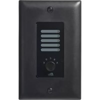
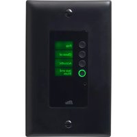
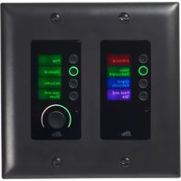
Front Panel
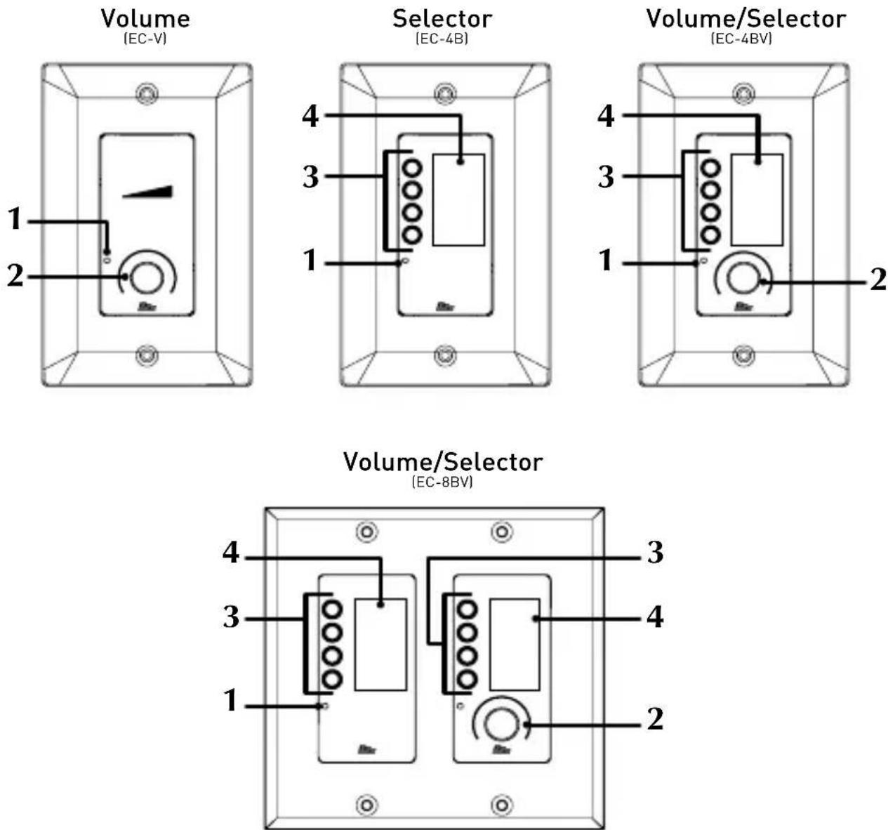
1. Locate Button
This small pinhole provides access to the Locate button. Pressing the Locate button allows an online controller to be easily identified within Audio Architect™, see 'Locate' on page 15 for further information on functions performed with this button.
2. Encoder w/ Pushbutton & Light Ring
This dual-function encoder provides rotary and pushbutton control. An RGB light ring around the encoder provides volume setting indication, signal level metering, and mute status.
3. Selector Buttons
These RGB, LED-backlit buttons can be programmed to control source selection, preset selection, or any other assignable state variable and support selection between eight different colors.
4. LCD display
This RGB display is broken up into four sections to correspond with the selector buttons. The display can be programmed to display text or graphic icons and supports selection between eight different colors.
Mechanical Installation
The US versions of the Contrio wall controllers were designed to fit into standard 1-gang or 2-gang US wall boxes. The EU versions were designed to fit into standard EU 1-gang or 2-gang square and round boxes. Screws are provided with each controller to fix them in place. Both 3mm and 3.5mm screws are provided with EU versions for mounting as required.
Dimensions of each Ethernet wall controller model are shown below.
EC-V-EU, EC-4B-EU, EC-4BV-EU (EU Versions)
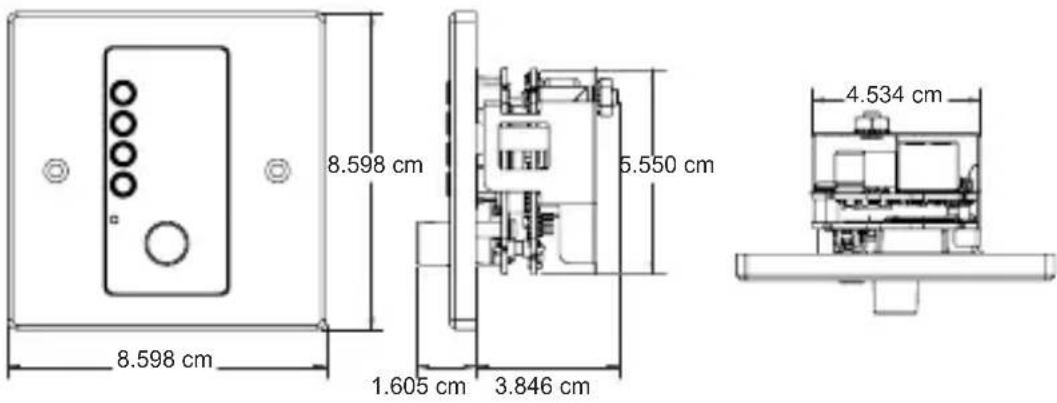
text_image
8.598 cm 8.598 cm 1.605 cm 3.846 cm 5.550 cm 4.534 cmEC-V, EC-4B, EC-4BV (US Versions)
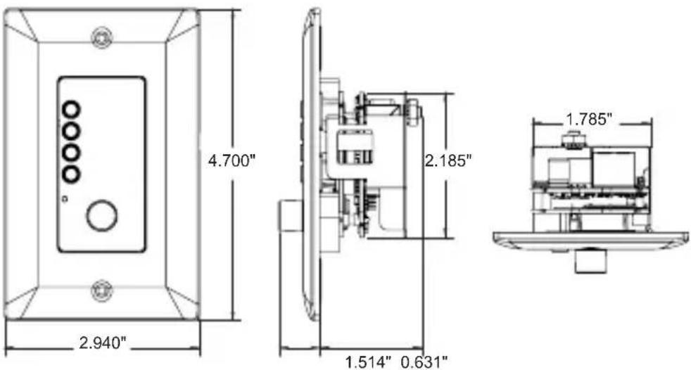
text_image
4.700" 2.940" 2.185" 1.514" 0.631" 1.785"EC-8BV-EU (EU Version)
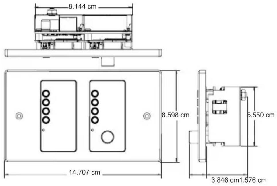
text_image
9.144 cm 8.598 cm 14.707 cm 5.550 cm 3.846 cm 1.576 cmEC-8BV (US Version)
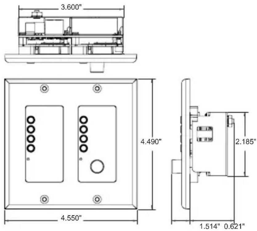
text_image
3.600" 4.490" 2.185" 1.514" 0.621" 4.550"Connections
Both power and network connectivity are supplied to the Ethernet Contrio controllers via their RJ-45 Ethernet ports. Power must be supplied to the controllers via an IEEE802.3af compliant Power over Ethernet (PoE) device. Note that PoE+ (IEEE802.3at compliant) devices can also be used with the Contrio controllers as they are backwards compatible with the IEEE802.3af standard. There are two types of PoE devices which can be used to supply power to the Contrio controllers, they are:
- An in-line IEEE802.3af compliant power injector (referred to as a 'midspan').
- An IEEE802.3af compliant PoE enabled network switch (referred to as an 'endspan' or 'endpoint').
Typical midspan Ethernet powering devices include:
3Com® Single-Port 802.3at Gigabit PoE Midspan Solution - P/N: 3CNJPSE
3Com® Power over Ethernet Multiport Midspan Solution - P/N: 3CNJPSE24
Typical endspans (Ethernet switches) with PoE enabled ports include:
Netgear® ProSafe™ 24-Port Gigabit Smart Switch - P/N: GS728TP
Dell® PowerConnect™ 3524P 24-Port PoE Switch - P/N: 3524P
An Ethernet Contrio wall controller connects to a Soundweb London network via its Ethernet port, either through a midspan then into the rear of a rackmount device (e.g., BLU-806) or through a PoE compliant Ethernet switch (endspan) using either straight-through or crossover Cat 5 cables (see connection diagarms on next page).
If a DHCP enabled switch has been implemented on the network, the Contrio contollers will be assigned IP addresses from the DHCP server. If no DHCP server is present, an Auto-IP compliant IP address will be assigned. Static IP addressing is also supported via Audio Architect. See the important note about DHCP in the Audio Architect help file for further information.
Connection Diagrams
Using A Midspan
Soundweb London Device (e.g., BLU-806)
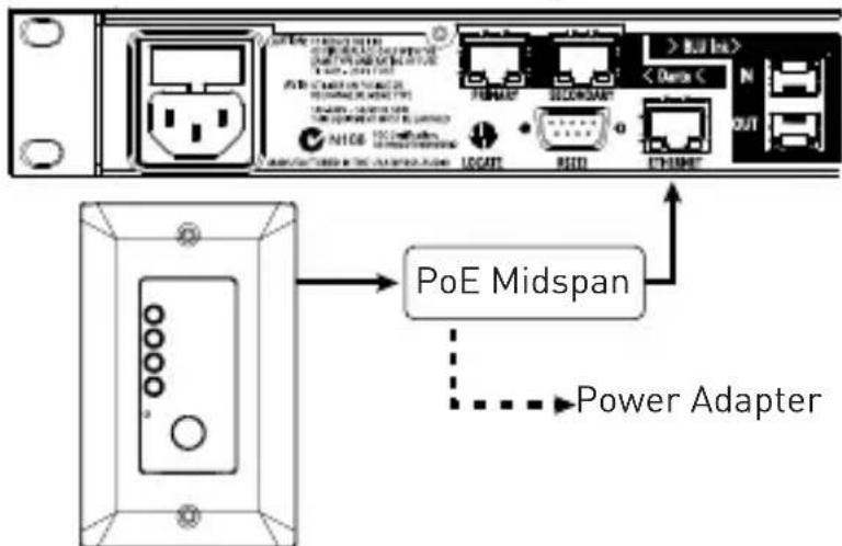
text_image
PoE Midspan Power AdapterEthernet Contrio Controller
n Endspan
Soundweb London Device (e.g., BLU-806)
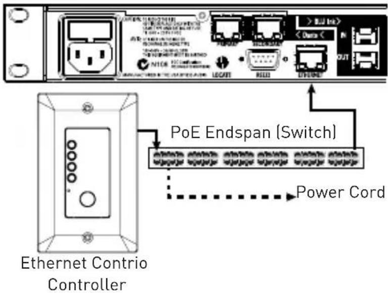
text_image
PoE Endspan (Switch) Power Cord Ethernet Contrio ControllerGround Lug Connection (Optional)
A ground lug is provided on all Contrio controllers for connecting to an earth ground. This can provide further protection against ESD (Electrostatic Discharge). In most cases this connection should not be necessary. However, if you experience irregular behavior when testing a Contrio controller, connecting this lug to an earth ground may resolve the issue.
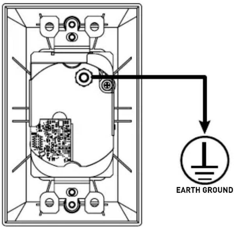
text_image
EARTH GROUNDLocate
Each Ethernet Contrio controller has a pinhole Locate pushbutton on the faceplate that will trigger the locate function.
Pressing the Locate button using a small, long object, such as a paperclip, will cause a controller's front panel LEDs to flash. If the controller is programmed and online with Audio Architect, the corresponding controller icon will also flash in the Audio Architect design file to identify it.
NOTE: Wall controllers can also be located using Netsetter from within Audio Architect. When the locate function is activated in Audio Architect, the controller's LEDs will flash to indicate that the wall controller is being located from the software.
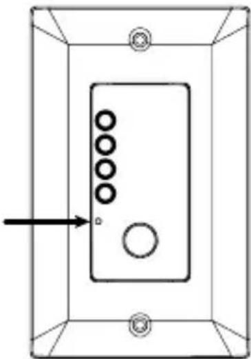
natural_image
Simple line drawing of a rectangular frame with circular holes and a central circle, no text or symbols present.Boot Menu Mode
On controllers with a display, controller information such as IP address and subnet mask can be displayed by entering Boot Menu Mode. This information can be used for installation and troubleshooting purposes and, once installation is complete, can be locked out from within Audio Architect to keep network address information private.
To access and use the Boot Menu:
- Power off the controller.
- Apply power to the controller while pressing and holding the Locate button. Keep the Locate button held for about 30 seconds.
- Press the corresponding button to select the desired menu option.
NOTE: The Ethernet Contrio controllers (with the exception of the EC-V model) also have available Demo Modes which can be used to simulate each controller's control capability. In the event you find the controller behaving strangely after accidentally entering this mode, simply power cycle the device to exit Demo Mode. This mode is generally reserved for sales associates and serves no practical purpose during installation.
Factory Reset & Restart
Factory Reset
The Factory Reset will revert an Ethernet Contrio controller back to its unconfigured, factory-default state by deleting its configuration and clearing any set IP address information.
To Factory Reset a controller:
- Power off the controller.
- Apply power to the controller while pressing and holding the Locate button. Keep the Locate button held for about 30 seconds.
- If using an EC-V, the controller will now perform the Factory Reset and you don't need to perform any of the following steps. If using the EC-4B, EC-4BV, or EC-8BV, the Boot Menu options should now be displayed and you can continue to step 4.
- Select the 'Factory Reset' option by pressing the corresponding button. Note that selecting the 'Restart' option will restart the controller without clearing the configuration and IP address.
- The Factory Reset will now be performed.
Restart
Perform the Restart procedure if an Ethernet Contrio controller becomes unresponsive. This procedure will restart a controller without having to disconnect power to the device. Configuration and IP address information will not be lost when performing the Restart procedure.
To Restart a controller:
- With the controller powered on, press and hold any button or encoder for approximately 20 seconds.
- The controller will now power cycle and reboot with the current configuration and IP settings.
NOTE: There is no Restart procedure for the EC-V controller. To Restart an EC-V controller, power must be disconnected from the controller then reconnected, or the PoE device supplying power must be power cycled.
Other Functions
The following functions are configured using the Contrio Default Control Panel from within Audio Architect.
Sleep Function
When enabled, the Sleep function allows the Contrio controller's LEDs and displays to 'sleep' (turn off) after a specified period of operator inactivity, which can be entered in the 'Sleep Delay' field. Any button press or rotary movement by the operator will 'wake up' the controller and restore the display and LEDs to show current system status. Note that there is a 2 second delay after 'wake up' before the controls will again become active.
If the 'Lockout On Sleep' function is also enabled, then, when the controller 'wakes up', it will automatically enter its 'locked' state. Button and rotary actions on the unit will have no effect until the required security PIN number is entered, see 'Lockout Active Function (Excludes EC-V Model)' on page 18 for further information.
To wake a controller:
- While the controller is in the 'sleep' state, either press a button or turn the rotary encoder.
NOTE: Although the EC-V controller cannot be unlocked directly from the controller, it can be unlocked by other means – such as by using Soundweb London logic or a Control Input contact closure.
Sleep Delay Time
When the Sleep function is enabled, this field allows you to enter the amount of time it will take, after no operator activity, before a Contrio controller will go to 'sleep' by extinguishing its LEDs.
Lockout On Sleep Function (Excludes EC-V Model)
When 'waking' a 'sleeping' controller, this function locks out the controller until the correct PIN has been entered, see 'Lockout Active Function (Excludes EC-V Model)' on page 18 for further information.
Lockout Active Function (Excludes EC-V Model)
The 'Lockout Active' button on the Contrio Default Control Panel provides a mechanism to disable a Contrio controller until a security PIN is entered. This might be appropriate when the controller is located in a public area and restricted access to the controller functions is required. When the unit is 'locked', any button press or rotary movement will be ignored.
The desired 4-digit security PIN for a Contrio controller may be configured in the controller's 'Properties' section from within Audio Architect and is composed of the digits 1, 2, 3, and 4. This security PIN only becomes active on the controller if the Lockout Active button is enabled and after going online and loading the design file to the controller.
To unlock a locked controller:
- While the controller is in the 'locked' state, either press any button or turn the rotary encoder. All LEDs on the controller will flash RED, indicating it is locked and the message 'Controller Locked – Push and hold any button to enter PIN' will be displayed.
- The numbers 1, 2, 3, and 4 will be displayed next to the buttons. Simply press the corresponding buttons to enter the PIN sequence.
- When a correct PIN sequence is entered, all LEDs on the controller will flash GREEN twice, confirming the unit is now 'unlocked' and normal operation of the buttons and rotary control will be possible.
NOTE: If the PIN sequence entered is incorrect, the controller will flash RED twice, indicating it is still in the 'locked' state and the above procedure must be performed again.
You can use Audio Architect to unlock a currently locked Contrio controller (e.g., If you have forgotten the Lockout PIN).
To unlock a locked controller via Audio Architect:
- Load the Audio Architect (AA) design file which matches the controller.
- From the main AA view, left-click on the corresponding controller.
- In the 'Properties' window select the Configuration Tab then delete all characters from the 'Lockout PIN' field.
- In the main view, right-click on the controller and select the 'Show Default Control Panel' option.
-
Disable both the 'Lockout on Sleep' and 'Lockout Active' buttons.
-
Go online and load the design to the Contrio controller.
-
The controller will now be unlocked.
LED Maximum Brightness
There are 4 selectable brightness levels for a Contrio controller, they are: LED Maximum Brightness 1 (dim) to 4 (bright). These values can be changed in the controller's Default Control Panel, which is accessed by right-clicking on the controller from the main view in Audio Architect and selecting the 'Default Control Panel' option. Here are a few things to note about LED functionality and the Maximum Brightness parameter:
- Disabled controls, such as unavailable channels on a source selector, will be unlit.
- Inactive but selectable controls will be unlit (e.g., where a controlled parameter has gone offline).
- Active or selected controls will be shown using the currently selected 'LED Maximum Brightness' setting.
- In most cases, it is recommended that a high Maximum Brightness setting be used (e.g., 4), as this will allow a higher contrast between active and inactive LED states.
Technical Specifications
Maximum network cable length: 328 feet (100 meters)
Power consumption: 300mA max at 48VDC
Required power: 44-57VDC, 13W
( certified POE power adaptor)
Recommended Ethernet cable wiring: VW-1 Rated, 48VDC, 13W
Operating temperature range: 0^ to 45^ C ( 32^ to 113^ F)

text_image
BSS®by HARMAN
Phone: (801) 566-8800
Website: bssaudio.com
Support: bssaudio.com/en-US/support
Contrio Install Guide
PN: 5046474-C
BSS Audio is a registered trademark of HARMAN
© 2017 HARMAN
All rights reserved
Printed in Malaysia