— ATV — Mode d'emploi PDF")
YXZ1000R SS (2024) - ATV YAMAHA - Free user manual and instructions
Find the device manual for free YXZ1000R SS (2024) YAMAHA in PDF.
| Product type | Competition off-road quad |
| Brand | Yamaha |
| Model | YXZ1000R SS (2024) |
| Overall length | 3147 mm |
| Overall width | 1636 mm |
| Overall height | 1750 mm |
| Wheelbase | 2300 mm |
| Ground clearance | 310 mm |
| Curb weight | 725.0 kg |
| Maximum load (driver + passenger + cargo + accessories) | 303.0 kg |
| Gross vehicle weight rating | 1065 kg |
| Engine | 3-cylinder inline, 998 cc, liquid-cooled, DOHC |
| Fuel | Unleaded gasoline 91 RON (E10 accepted), tank 34 L |
| Transmission | 6-speed sequential + reverse, YCC-S semi-automatic (manual or automatic) |
| Drivetrain | On-Command: 2WD, 4WD, 4WD with differential lock |
| Front/rear suspension | Double wishbone with preload, rebound and compression adjustments (high and low speed) |
| Front/rear brakes | Hydraulic disc |
| Front tires | 29 x 9.00R-14 (MAXXIS M917 BIGHORN) |
| Rear tires | 29 x 11.00R-14 (MAXXIS M918 BIGHORN) |
| Battery | 12 V, 28 Ah |
| Lighting | LED headlights, LED tail/brake light |
| DC accessory outlet | 12 V, 10 A (120 W) |
| Cargo bed capacity | 136 kg |
| Glove box capacity | 4.5 kg |
| Seating | Driver + 1 passenger |
Frequently Asked Questions - YXZ1000R SS (2024) YAMAHA
User questions about YXZ1000R SS (2024) YAMAHA
0 question about this device. Answer the ones you know or ask your own.
Ask a new question about this device
Download the instructions for your ATV in PDF format for free! Find your manual YXZ1000R SS (2024) - YAMAHA and take your electronic device back in hand. On this page are published all the documents necessary for the use of your device. YXZ1000R SS (2024) by YAMAHA.
USER MANUAL YXZ1000R SS (2024) YAMAHA
en: Sorting label and “Triman” mark for this manual, in compliance with French regulation. (Article 17 of the French AGEC Law and Decree no. 2021-835 of 29 June 2021)
"2WD/4WD/DIFF. LOCK"......5-22
Embrayage YCC-S....6-9
Visserie....6-9
Embrayage YCC-S....9-60
natural_image
Mechanical assembly diagram showing engine components and suspension system (no text or labels)natural_image
Mechanical assembly diagram showing a lever mechanism with no visible text or symbols- Étiquette de modèle
text_image
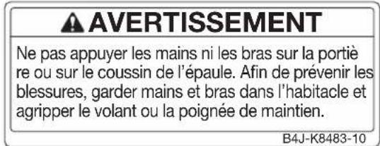
WARNING Do not rest hands or arms on door or shoulder bolster. To avoid Injury, keep hands and arms completely Inside the vehicle by holding the steering wheel or handhold. B4J-K8483-002
text_image
1HP-F2259-214
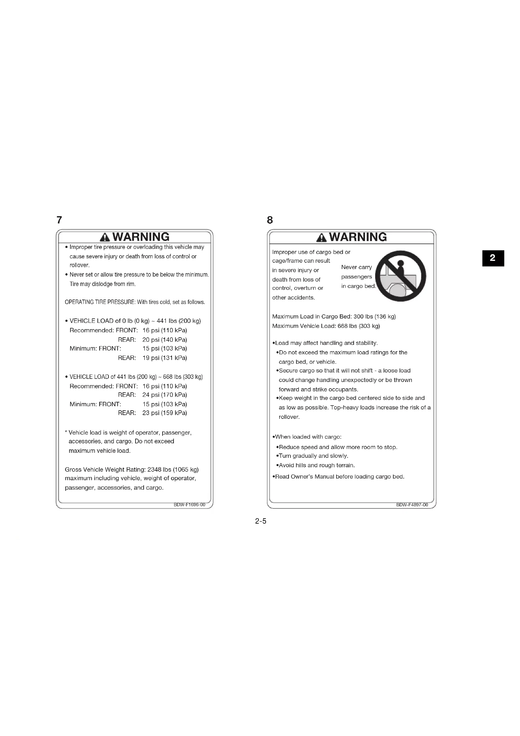
- Improper tire pressure or overloading this vehicle may cause severe injury or death from loss of control or rollover.
- Never set or allow tire pressure to be below the minimum. Tire may dislodge from rim.
OPERATING TIRE PRESSURE: With tires cold, set as follows.
- VEHICLE LOAD of 0 lb (0 kg) \~ 441 lbs (200 kg)
Recommended: FRONT: 16 psi (110 kPa)
REAR: 20 psi (140 kPa)
Minimum: FRONT: 15 psi (103 kPa)
REAR: 19 psi (131 kPa)
• VEHICLE LOAD of 441 lbs (200 kg) \~ 668 lbs (303 kg)
Recommended: FRONT: 16 psi (110 kPa)
REAR: 24 psi (170 kPa)
Minimum: FRONT: 15 psi (103 kPa)
REAR: 23 psi (159 kPa)
* Vehicle load is weight of operator, passenger, accessories, and cargo. Do not exceed maximum vehicle load.
Gross Vehicle Weight Rating: 2348 lbs (1065 kg) maximum including vehicle, weight of operator, passenger, accessories, and cargo.
BDW-F1696-00
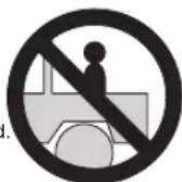
WARNING
Improper use of cargo bed or
cage/frame can result
in severe injury or
death from loss of
control, overturn or
other accidents.
Never carry passengers in cargo bed
Maximum Load in Cargo Bed: 300 lbs (136 kg)
Maximum Vehicle Load: 668 lbs (303 kg)
- Load may affect handling and stability.
- Do not exceed the maximum load ratings for the cargo bed, or vehicle.
- Secure cargo so that it will not shift - a loose load could change handling unexpectedly or be thrown forward and strike occupants.
- Keep weight in the cargo bed centered side to side and as low as possible. Top-heavy loads increase the risk of a rollover.
- When loaded with cargo:
- Reduce speed and allow more room to stop.
•Turn gradually and slowly. - Avoid hills and rough terrain.
- Read Owner's Manual before loading cargo bed.
BDW-F4897-00
9
WARNING
Improper Use of Off-Highway Vehicles Can Cause Severe Injury or Death
Drive Responsibly
Avoid loss of control and rollovers:
- Avoid abrupt maneuvers, sideways, sliding, skidding, or fishtailing, and never do donuts.
- Slow down before entering a turn.
- Avoid hard acceleration when turning, even from a stop.
- Plan for hills, rough terrain, ruts, and other changes in traction, and terrain.
- Avoid paved surfaces.
- Avoid side hilling (riding across slopes).
- Do not allow anyone to ride the cargo bed.
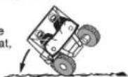
Rollovers have caused severe injuries and death, even on flat, open areas.
Require Proper Use of Your Vehicle
Do your part to prevent injuries:
- Do not allow careless or reckless driving.
- Make sure operators are 16 or older with valid driver's license.
- Do not let people drive or ride after using alcohol or drugs.
- Do not allow operation on public roads (unless designated for off-highway vehicle access)
- collisions with cars and trucks can occur.
- Do not exceed seating capacity; 1 passenger.
16
g.
h valid
-
g alcohol or
(unless
ess)
cur.
senger.
Read Owner's Manual
Read Tips Guide for the Recreational Off-Highway Vehicle Driver Follow All Instruction and Warnings

DEIVER
WARNING
Improper Use of Off-Highway Vehicle Can Cause Severe Injury or Death Be Prepared
- Fasten seat belts.
- Wear an approved helmet, eye protection and protective gear.
- Driver must be able to comfortably reach all controls while sitting upright with back against seat.
- Passengers must be able to reach the handhold while keeping feet flat on floor and sitting upright with back against seat.
- Stay completely inside the vehicle.
Pay Attention and Plan Ahead If you think or feel the vehicle may tip or roll, reduce your risk to injury:
- Keep a firm grip on the steering wheel or handhold and brace yourself.
- Do not put any part of your body outside of the vehicle for any reason.
- Do not hold the cage and door.
BAS-F1568-01
10

text_image
E10E5 B4F-F817K-0011

12
WARNING

Moving parts can crush and cut. Do not operate engine with guard removed.
AVERTISSEMENT
natural_image
Diagram of a vehicle with wheels and a moving arrow indicating motion (no text or symbols)text_image
Technical diagram of a mechanical component with numbered parts labeled 1 to 4FBU31232 Position contact "
natural_image
Close-up of a kitchen sink with two circular gauges and a handle, showing no text or symbolsnatural_image
Mechanical assembly diagram showing internal components and parts (no readable text or symbols)natural_image
Mechanical assembly diagram showing a component with labeled parts (no readable text or symbols)- Pédale de frein
text_image
Diagram of a vehicle control panel with labeled parts 1 and 2, showing mechanical components and directional arrows.natural_image
Close-up of a mechanical device with a knob and control panel (no visible text or symbols)- Sélecteur de marche
text_image
Technical diagram of a vehicle steering wheel with numbered components and directional arrows indicating motion or flow.natural_image
Technical diagram of a vehicle's front bumper and dashboard, showing labeled components (no readable text or symbols)text_image
Technical diagram of a mechanical component with labeled parts 1 and 2-
Portière
-
Poignée
FBU33461
Sièges
natural_image
Mechanical assembly diagram showing internal components and motion indicators (no readable text or symbols)natural_image
Mechanical assembly diagram showing internal components and a numbered label (1, 1, 1) with no readable text or symbols.natural_image
Mechanical assembly diagram showing a vehicle's internal components and wiring (no text or labels visible)FBU34993
natural_image
Mechanical assembly diagram showing a vehicle's internal components and a close-up of a lever mechanism (no text or labels visible)natural_image
Interior view of a car dashboard and steering wheel assembly (no visible text or symbols)natural_image
Technical diagram of a vehicle chassis frame with labeled components (no text or symbols present)natural_image
Mechanical component diagram showing a lever mechanism with numbered parts (1 and 2), no readable text or symbols present.natural_image
Mechanical assembly diagram showing a component with labeled parts (no readable text or symbols)- Compartiment de rangement
natural_image
Mechanical assembly diagram showing internal components with no visible text or symbols- Porte-gobelets
FBU35022
Benne
FWB03250

AVERTISSEMENT
natural_image
Technical diagram of a vehicle chassis frame with springs and structural components (no text or symbols)- Crochet d'amarrage
Limite de charge maximum : 136.0 kg (300 lb)
natural_image
Top-down view of a YAMAHA vehicle chassis frame with visible structural components and tire tracks (no text or symbols beyond branding)- Support de drapeau
FCB03010
ATTENTION
natural_image
Mechanical assembly diagram showing internal components of a vehicle or engine (no text or labels visible)text_image
Technical diagram of a mechanical assembly with numbered components and an inset showing a helical spring assembly.text_image
Technical diagram of a mechanical assembly with numbered components and a magnified detail view labeled (b)Distance B = 19.2 mm (0.76 in)
Distance B = 26.8 mm (1.06 in)
Distance B = 39.5 mm (1.56 in)
natural_image
Technical illustration of a vehicle chassis showing suspension systems and tire components (no text or symbols)text_image
Technical diagram of a mechanical assembly with numbered components and an inset showing a helical spring assembly detail.text_image
Technical diagram of a mechanical assembly with numbered components and labeled parts (b)Distance B = 45.3 mm (1.78 in)
Distance B = 58.0 mm (2.28 in)
Distance B = 70.7 mm (2.78 in)
natural_image
Interior view of a vehicle dashboard with lever and handle (no visible text or symbols)natural_image
Line drawing of a hand using a tool to mark the wheel rim and wheel (no text or symbols)text_image
D R N 2 1text_image
Diagram of a vehicle steering wheel with numbered components and directional arrows indicating motion or flownatural_image
Interior view of a vehicle dashboard and steering wheel (no visible text or symbols)text_image
Technical diagram of a toy car with numbered parts labeled 1, 2, and 3text_image
Technical diagram of a multi-axle off-road vehicle with numbered components labeled 1, 2, and 3.natural_image
Line drawing of a medical procedure showing hands holding a tool with an arrow indicating direction (no text or symbols)text_image
Technical diagram showing three labeled parts of a mechanical assembly, likely illustrating a fastening or locking mechanism.text_image
Technical diagram showing three steps of a cable buckle clamp installation, labeled 1, 2, and 3.natural_image
Illustration of a worker inside a heavy machinery frame with a circular prohibition symbol (no text or symbols present)Poignée du passager
natural_image
Illustration of a person operating a heavy-duty off-road vehicle (no text or symbols visible)natural_image
Mechanical assembly diagram showing a pipe connection inside a vehicle (no text or symbols visible)natural_image
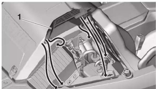
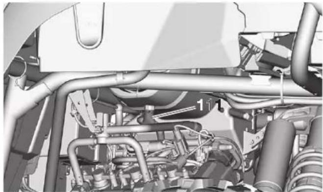
Mechanical assembly diagram showing a pipe connection with labeled parts (1, 2, 11), no readable text or symbols beyond labelstext_image
Technical diagram of a vehicle interior with labeled components, showing hoses and parts numbered 1 and 22.text_image
Diagram illustrating a mechanical assembly or tool operation, showing a curved pipe with labeled component '1' and directional arrow.natural_image
Illustration of a worker inside a large circular prohibition symbol, surrounded by heavy machinery (no text or symbols present)Plancher
natural_image
Line drawing of a hand gripping a piece of material, no text or symbols presentFBU36754
PRISE EN MAIN DU VÉHICULE
natural_image
Diagram of a vehicle moving on a surface with an arrow indicating motion (no text or symbols present)natural_image
Diagram of a vehicle moving on a surface with an arrow indicating motion direction (no text or symbols)natural_image
Mechanical assembly diagram showing a component with labeled parts (111), no readable text or symbols present.text_image
Technical diagram of a mechanical assembly with numbered components, likely a valve or connector assembly.natural_image
Technical diagram of a mechanical assembly with numbered components (1 and 2), no visible text or symbols.-
Capot A
-
Capot B
Capot A
natural_image
Mechanical assembly diagram showing fluid flow paths around a vehicle chassis (no text or labels)Capot B
text_image
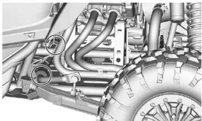
Technical diagram of a vehicle's rear suspension system with numbered components and an inset showing a circular component.text_image
Technical diagram of a mechanical assembly with numbered components labeled 1, 2, 3, and 3.natural_image
Mechanical assembly diagram showing internal components and labeled parts (no readable text or symbols)- Capot B
N.B.
natural_image
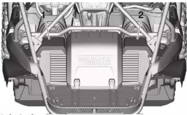
Interior view of a sports racing arena with numbered equipment (1 and 2), no visible text or symbols- Cache A
- Cache B
text_image
1 2 YAMAHA- Cache C
- Cache D
Cache A
text_image
Technical diagram of a mechanical assembly with numbered components and directional arrows indicating motion or flow.- Cache A
- Patte de fixation
natural_image
Interior view of a car dashboard and steering wheel assembly (no visible text or symbols)Cache B
text_image
Diagram of car interior components with numbered labels pointing to various compartments and partstext_image
Technical diagram of a vehicle's internal components with numbered parts labeled 1, 2, and 3text_image
Technical diagram of a vehicle's interior components with numbered parts and an arrow indicating direction or movement.natural_image
Interior view of a vehicle showing engine compartment with hoses and structural elements (no visible text or symbols)natural_image
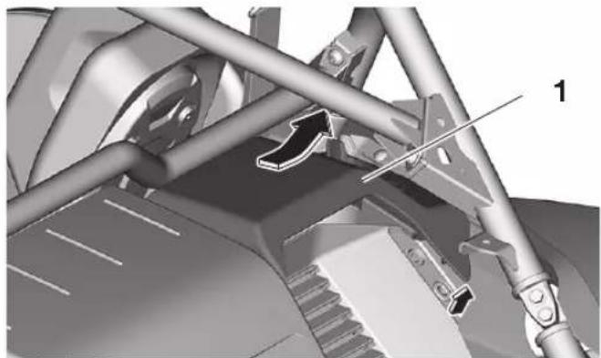
Top-down view of a vehicle chassis showing structural components and a YAMAHA logo (no readable text or symbols beyond branding)- Cache C
- Cache D
- Onglet
text_image
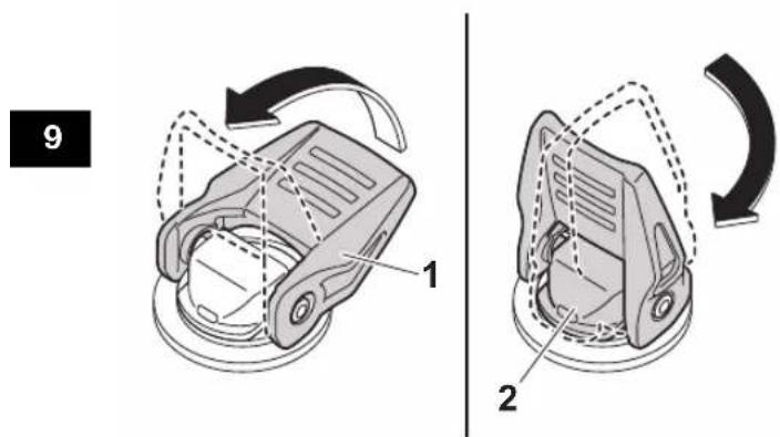
9 1 2natural_image
Mechanical assembly diagram showing a bracket with labeled parts and directional arrows (no readable text or symbols)- Cache C
natural_image
Mechanical assembly diagram showing a lever mechanism with labeled component '1' (no text or symbols beyond label)- Cache D
natural_image
Mechanical assembly diagram showing internal components and fluid flow paths (no text or symbols)- Cache C
natural_image
Mechanical assembly diagram showing internal components and fluid flow paths (no text or labels)text_image
Technical diagram of an electronic circuit board with labeled components 1 and 3text_image
Diagram of an industrial facility with numbered annotations pointing to structural elements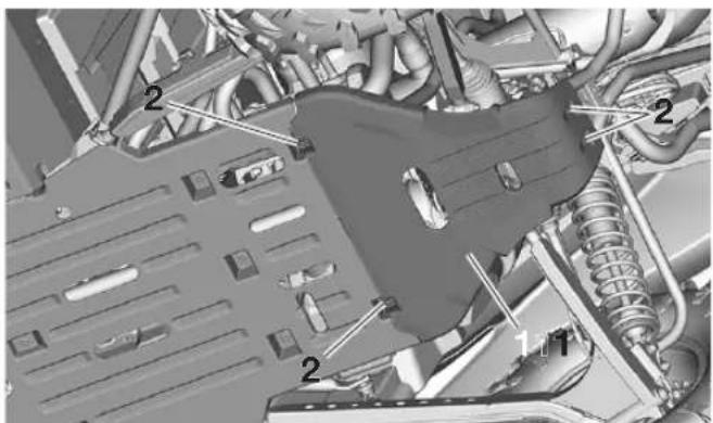
text_image
Technical diagram of an automotive engine bay with numbered components and labeled partsnatural_image
Technical line drawing of a bolt with hexagonal head and threaded base (no text or symbols)- Boulon A
- Boulon B
natural_image
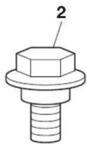
Technical drawing of a hexagonal bolt with threaded base (no text or symbols)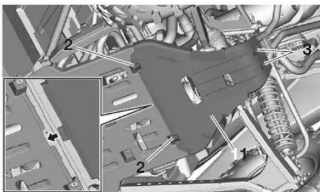
text_image
Technical diagram of an automotive engine bay with numbered components and a magnified inset showing internal parts.natural_image
Aerial view of a large urban area with visible roads, buildings, and a marked location (no text or symbols present)- Vis
text_image
1Couple de serrage :
text_image
Technical diagram of an aircraft fuselage with numbered components and a magnified inset showing internal structure.natural_image
Aerial view of a multi-lane road with vehicles and traffic lanes, marked with arrows and numbers 1 and 2 (no readable text or symbols)natural_image
Aerial view of a large electronic circuit board with visible components and wiring, showing no readable text or symbols.text_image
Technical diagram of an electronic device with numbered components and labeled parts- Boulon A
- Boulon B
- Boulon C
text_image
Technical diagram showing labeled mechanical components with numbered parts, including a threaded rod and tool interacting with a mechanical device.text_image
Technical diagram of a mechanical assembly with numbered components labeled 1 and 2natural_image
Mechanical assembly diagram showing internal components like gears and linkages (no text or labels)natural_image
Interior view of a vehicle engine bay with hoses and control panel (no visible text or symbols)text_image
Technical diagram showing a mechanical assembly with labeled parts 1 and 2, including a magnified inset of the component.text_image
Technical diagram of a vehicle engine component with labeled parts and an inset showing a bolt assembly detail.natural_image
Illustration of a hand pouring liquid into a mechanical component (no text or symbols visible)natural_image
Mechanical assembly diagram showing a vehicle chassis with labeled parts (no readable text or symbols)natural_image
Technical line drawing of a mechanical component with labeled part 1 (no text or symbols beyond label)natural_image
Mechanical assembly diagram showing a vehicle suspension system with no visible text or symbolstext_image
Technical diagram of a mechanical assembly with labeled parts, including a hook and three numbered components.text_image
Technical diagram showing a mechanical assembly with labeled parts, including a magnified inset of a bolt and nut assembly.natural_image
Illustration of a hand pouring liquid into a mechanical component (no text or symbols visible)text_image
Technical diagram of a server rack with labeled components and a tool interacting with the rack.natural_image
Technical line drawing of a mechanical component with labeled part 1 (no text or symbols beyond label)natural_image
Interior view of a server rack with visible wiring and mechanical components (no text or symbols)text_image
Technical diagram of a vehicle suspension system with labeled components and an inset showing parts 1, 2, 3, and 4.natural_image
Mechanical assembly diagram showing gear and shaft components with no visible text or symbolstext_image
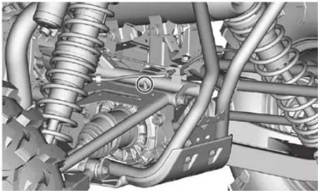
Technical diagram of a vehicle suspension system with labeled components and an inset showing internal wiring connections.natural_image
Mechanical assembly diagram showing a bolted component with two labeled parts (1 and 2), no readable text or symbols present.natural_image
Close-up of a vehicle's internal engine and suspension system (no visible text or symbols)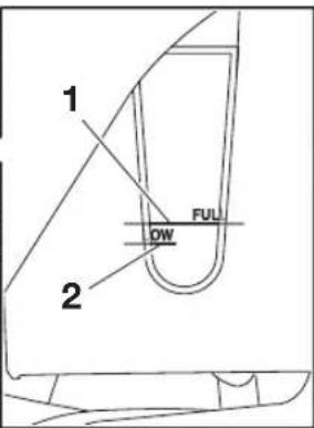
text_image
1 FUL DW 2natural_image
Mechanical assembly diagram showing interconnected pipes and gears (no text or symbols visible)natural_image
Mechanical assembly diagram showing suspension components and linkage (no text or labels)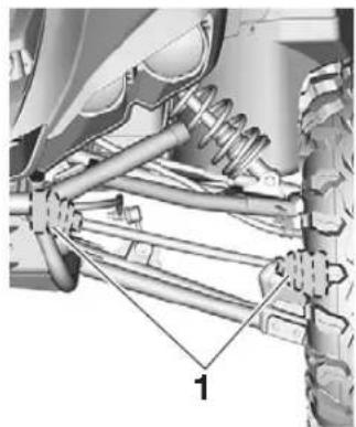
natural_image
Mechanical assembly diagram showing suspension components and labeled parts (no text or symbols present)natural_image
Mechanical assembly diagram showing suspension components and labeled parts (no readable text or symbols)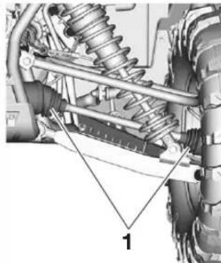
natural_image
Mechanical assembly diagram showing suspension components and labeled parts (no text or symbols present)natural_image
Technical line drawing of a coiled spring with a 1mm dimension标注 (no text or symbols beyond the number)natural_image
Technical diagram of a vehicle's internal components, showing engine, tire, and structural assembly (no text or labels)text_image
OPEN 3 1 2natural_image
Mechanical assembly diagram showing pipes, gears, and components (no readable text or symbols)natural_image
3D mechanical assembly diagram showing a cylindrical component with labeled parts 1 and 2, and a coiled spring-like structure (no text or symbols beyond labels)text_image
Illustration showing hand cleaning and prohibition of a tool, with text labels in English.natural_image
Technical illustration of a mechanical assembly with pipe fittings and a close-up inset showing internal components (no text or symbols)text_image
Technical diagram of a mechanical assembly with labeled component '1' and directional arrow indicating rotation or movement.- Repère d'alignement
natural_image
Engine bay with visible internal components and pipes (no text or symbols)natural_image
Close-up mechanical assembly showing internal components and tubing (no visible text or symbols)natural_image
Mechanical assembly diagram showing engine components and suspension parts (no text or labels)natural_image
Mechanical assembly diagram showing internal components with no visible text or symbolstext_image
Technical diagram of a mechanical component with labeled parts 1, 2, and 3natural_image
Mechanical assembly diagram showing a flanged component with attached springs and shafts, plus an inset detail of a cross-section with dimension line (no text or labels)natural_image
Mechanical assembly diagram showing pipe connections and a magnified inset of a mechanical component (no text or symbols)text_image
Technical diagram of a vehicle engine component with labeled parts and three views showing internal components and assembly.natural_image
Mechanical gear shift lever assembly diagram showing keyway and intake components (no text or labels)natural_image
Interior view of a vehicle showing steering wheel, dashboard, and internal mechanical components (no visible text or symbols)natural_image
Technical line drawing of a mechanical assembly with a magnified inset showing a component (no text or symbols)Arrière
natural_image
Technical diagram of a vehicle's internal engine and suspension system, showing hoses, springs, and tire components (no text or labels)FBU35211
natural_image
Mechanical assembly diagram showing a vehicle's suspension system with springs and tires (no text or symbols)Arrière
natural_image
Mechanical assembly diagram showing suspension and release components (no text or labels)natural_image
Mechanical assembly diagram showing suspension components and engine components (no text or labels)natural_image
Mechanical assembly diagram showing suspension and release components (no text or labels)natural_image
Technical line drawing of a toy car showing front wheel, suspension components, and engine assembly (no text or symbols)natural_image
Technical illustration of a vehicle's front wheel assembly and suspension system (no text or symbols)FBU32610
Dépose d'une roue
natural_image
Technical line drawing of a tire wheel with labeled components (no text or symbols present)text_image
Technical diagram of a mechanical assembly with numbered components labeled 1, 2, and 3text_image
Technical diagram of a mechanical assembly with numbered components and labeled partstext_image
Technical diagram of an electrical component with numbered parts labeled 1, 2, and 3natural_image
Interior view of an electronic device showing wiring and components (no readable text or symbols)natural_image
Close-up of an electronic device component with visible wiring and connectors (no text or symbols)text_image
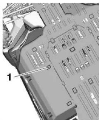
Technical diagram of a mechanical assembly with numbered components labeled 1 to 5Fusible principal: 70.0 A
text_image
(a)(a)(a) 1 (b)(b)Alésage × course: 80.0 × 66.2 mm (3.15 × 2.61 in)
Pédale, lubrification 9-63
Phares 9-76