
TruClear - Water pump Jandy - Free user manual and instructions
Find the device manual for free TruClear Jandy in PDF.
| Product Type | Residential pool chlorine generation system (salt chlorinator) |
| Power supply dimensions | 25.4 cm x 11.4 cm x 33 cm (10 in x 4.5 in x 13 in) |
| Electrolytic cell dimensions | 16.5 cm x 14 cm x 30.5 cm (6.5 in x 5.5 in x 12 in) |
| Power supply weight | 3.2 kg (7 lb) |
| Cell weight | 0.9 kg (2 lb) |
| Power supply | 120/240 V AC, 50/60 Hz, 4 A (120 V) / 2 A (240 V) |
| Output voltage | 25 V DC max. |
| Chlorine production | 18.4 g/h; equivalent to 442 g of free available chlorine per day |
| Max treated water volume | 132,000 liters (35,000 gallons) |
| Required salt level | 3.0 g/l (3000 ppm) |
| Max operating pressure | 3.4 bars (50 psi) |
| Minimum water flow rate | 76 L/min (20 gal/min) |
| Recommended water temperature | Above 16 °C (60 °F) |
| Main features | Chlorine production via salt electrolysis, automatic polarity reversal (every 5 h by default), Boost and Low modes, flow and temperature detection, RS485 connection for Jandy automation |
| Maintenance and cleaning | Weekly chlorine and pH check; monthly cell cleaning with diluted hydrochloric acid solution (1:10) if scaling; winterization: remove cell and store indoors |
| Safety | Automatic shut-off in case of no flow, overcurrent protection (15 A max), overheat detection, shut-off if cell housing damaged; must be installed by a qualified professional |
| Standards and certifications | ETL to UL 1081, certified CAN/CSA C22.2 No. 218.1, certified NSF/ANSI 50 |
| Available spare parts | Replacement cell (R0693900), housing (R0694000), O-ring (R0694100), power supply (R0802200), circuit board (R0802300), transformer (R0802400), winterizing plug (R0621900) |
| General information | Use only for residential pools and integrated spas; do not use with bromide-based products; requires stabilizer (cyanuric acid) between 30 and 50 ppm for outdoor pools; do not operate without water circulation (explosion risk) |
Frequently Asked Questions - TruClear Jandy
User questions about TruClear Jandy
0 question about this device. Answer the ones you know or ask your own.
Ask a new question about this device
Download the instructions for your Water pump in PDF format for free! Find your manual TruClear - Jandy and take your electronic device back in hand. On this page are published all the documents necessary for the use of your device. TruClear by Jandy.
USER MANUAL TruClear Jandy
Zodiac Pool Systems LLC
2882 Whiptail Loop # 100 Carlsbad, CA 92010
Zodiac Pool Systems Canada, Inc.
2-3365 Mainway, Burlington, ON L7M 1A6 Canada
natural_image
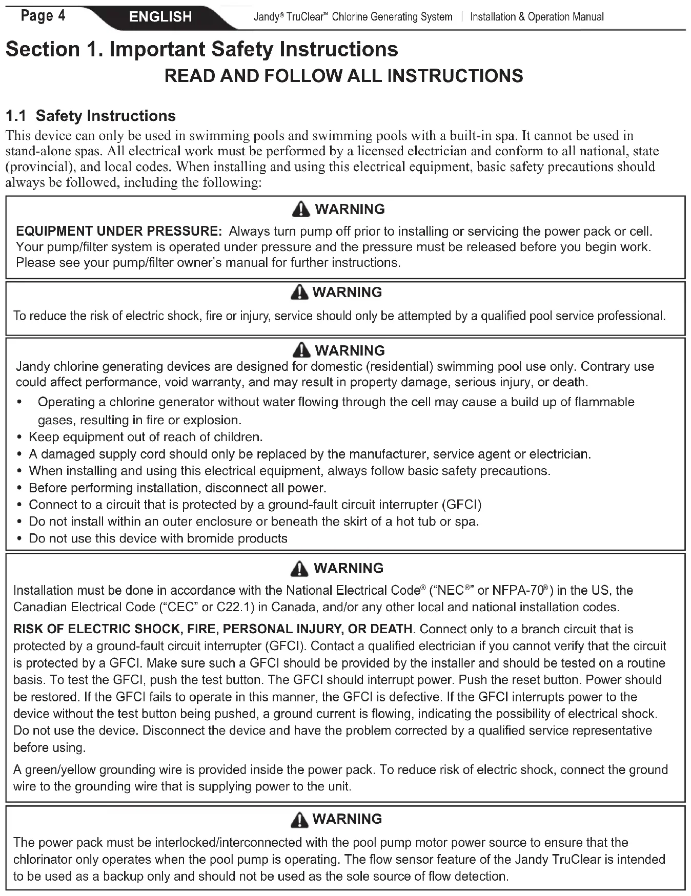
Exterior view of a Jandy Trucker brand water heater with coiled cable and warning label (no text-heavy elements)Controls bacteria and algae in swimming pool water
For Residential Pools
DOMESTIC
REGISTRATION NO. 32473 PEST CONTROL PRODUCTS ACT
WARNING
Operating Jandy TruClear™ models without water flow through the cell can cause a buildup of flammable gases which can result in FIRE OR EXPLOSION. READ THE LABEL AND OPERATION MANUAL BEFORE USING. KEEP OUT OF REACH OF CHILDREN.
Jandy TruClear™
Chlorine Generating System
WARNING
FOR YOUR SAFETY - This product must be installed and serviced by a contractor who is licensed and qualified in pool equipment by the jurisdiction in which the product will be installed where such state/provincial or local requirements exist. The maintainer must be a professional with sufficient experience in pool equipment installation and maintenance so that all of the instructions in this manual can be followed exactly. Before installing this product, read and follow all warning notices and instructions that accompany this product. Failure to follow warning notices and instructions may result in property damage, personal injury, or death. Improper installation and/or operation will void the warranty.

Improper installation and/or operation can create unwanted electrical hazard which can cause serious injury, property damage, or death.
ATTENTION INSTALLER - This manual contains important information about the in stal la tion, operation and safe use of this product. This information should be given to the owner/operator of this equipment.
Maximum Overcurrent Protection - 15A
Use Copper Conductors Only
Disconnect Power before Opening Service Cover
For Outdoor or Indoor Use
Electrical Requirements: 120/240 VAC 50/60 Hz
3 WIRE, 4/2 AMP
Maximum Output of Hypochlorous Acid is Equivalent to 442 g of Free Available Chlorine Per Day
3000 parts per million of salt
The maximum volume of water that can be treated with
one unit of TruClear is 132,000 liters (35,000 gallons) (132.0 m³)
For swimming pools, a range of 1-3 ppm of free available chlorine must be maintained.
Controls bacteria and algae in swimming pool water
Do not use this device with bromide products

Intertek
ETL LISTED
CONFORMS TO
UL STD 1081
Certified to
CAN/CSA C22.2
No. 218.1

Certified to
NSF/ANSI Standard 50
Notice to User
This pest control product is to be used only in accordance with the directions on the label. It is an offense under the Pest Control Products Act to use this product in a way that is inconsistent with the directions on the label. The user assumes the risk to persons or property that arises from any such use of this product.
Table of Contents
Section 1. Important Safety Instructions .....4
1.1 Safety Instructions....4
Section 2. General Description ....8
2.1 Product Specifications....8
2.2 Product Contents....9
Section 3. Installation Instructions....10
3.1 Materials and Tools.... 10
3.2 Installation Requirements....10
3.3 Installing the Power Pack....11
3.4 Installing the Cell 12
3.5 Wiring the Power Pack to the Power Source ... 13
3.6 Install RS485 for Jandy Automation 14
3.7 When Using In Non-automation Installations And With Jandy Variable Speed Pump...... 16
3.8 Bonding 16
3.9 Split Return Plumbing Instructions: For Infloor Cleaning Systems 16
Section 4. Pool Water Preparation....17
4.1 Determining Pool Size (Litres)....17
4.2 Determining Pool Size (Gallons) 17
4.3 Chemistry You Need to Know....17
4.4 Optimum Pool Water Conditions 18
4.5 Collecting a Water Sample 19
4.6 Salt (NaCl Sodium Chloride) 19
Section 5. Operating Instructions....21
5.1 Turning Power Pack On/Off (Manually) .....21
5.2 Select Language 21
5.3 Turning Power Pack On/Off (Using the Pump's External Timer)....21
5.4 Chlorine Output Level....21
5.5 BOOST/LOW Mode.....23
5.6 Polarity Reversal 23
Section 6. Maintenance....24
6.1 Weekly....24
6.2 Monthly.... 24
6.3 Cleaning the Cell 24
6.4 Winterizing....25
Section 7. Troubleshooting ...... 26
7.1 Problems and Corrective Action 26
Section 8. Display Readings......29
8.1 Display Reasons and Descriptions....29
Section 1. Important Safety Instructions
READ AND FOLLOW ALL INSTRUCTIONS
1.1 Safety Instructions
This device can only be used in swimming pools and swimming pools with a built-in spa. It cannot be used in stand-alone spas. All electrical work must be performed by a licensed electrician and conform to all national, state (provincial), and local codes. When installing and using this electrical equipment, basic safety precautions should always be followed, including the following:
WARNING
EQUIPMENT UNDER PRESSURE: Always turn pump off prior to installing or servicing the power pack or cell. Your pump/filter system is operated under pressure and the pressure must be released before you begin work. Please see your pump/filter owner's manual for further instructions.
WARNING
To reduce the risk of electric shock, fire or injury, service should only be attempted by a qualified pool service professional.
WARNING
Jandy chlorine generating devices are designed for domestic (residential) swimming pool use only. Contrary use could affect performance, void warranty, and may result in property damage, serious injury, or death.
- Operating a chlorine generator without water flowing through the cell may cause a build up of flammable gases, resulting in fire or explosion.
- Keep equipment out of reach of children.
- A damaged supply cord should only be replaced by the manufacturer, service agent or electrician.
- When installing and using this electrical equipment, always follow basic safety precautions.
- Before performing installation, disconnect all power.
- Connect to a circuit that is protected by a ground-fault circuit interrupter (GFCI)
- Do not install within an outer enclosure or beneath the skirt of a hot tub or spa.
- Do not use this device with bromide products
WARNING
Installation must be done in accordance with the National Electrical Code ^® (“NEC ^® ” or NFPA-70 ^® ) in the US, the Canadian Electrical Code (“CEC” or C22.1) in Canada, and/or any other local and national installation codes.
RISK OF ELECTRIC SHOCK, FIRE, PERSONAL INJURY, OR DEATH. Connect only to a branch circuit that is protected by a ground-fault circuit interrupter (GFCI). Contact a qualified electrician if you cannot verify that the circuit is protected by a GFCI. Make sure such a GFCI should be provided by the installer and should be tested on a routine basis. To test the GFCI, push the test button. The GFCI should interrupt power. Push the reset button. Power should be restored. If the GFCI fails to operate in this manner, the GFCI is defective. If the GFCI interrupts power to the device without the test button being pushed, a ground current is flowing, indicating the possibility of electrical shock. Do not use the device. Disconnect the device and have the problem corrected by a qualified service representative before using.
A green/yellow grounding wire is provided inside the power pack. To reduce risk of electric shock, connect the ground wire to the grounding wire that is supplying power to the unit.
WARNING
The power pack must be interlocked/interconnected with the pool pump motor power source to ensure that the chlorinator only operates when the pool pump is operating. The flow sensor feature of the Jandy TruClear is intended to be used as a backup only and should not be used as the sole source of flow detection.
WARNING
- The power pack must be installed at least 2 feet (0.6 m) vertically off the ground. Ensure the power pack is protected from direct water exposure from sprinklers, water runoff from rooftops and drainage.
- In the US, the power pack must be installed at least 1.5 m (5 ft.) from the inside wall of your swimming pool or spa; in Canada, the power pack must be installed at least 3 m (10 ft.) from the inside wall of your swimming pool or spa.
- In Canada, the Jandy chlorine generating electrolytic cell must be installed outdoors.
- The cell must be installed horizontally with the cord facing upwards to avoid buildup of flammable gases which can result in FIRE OR EXPLOSION.
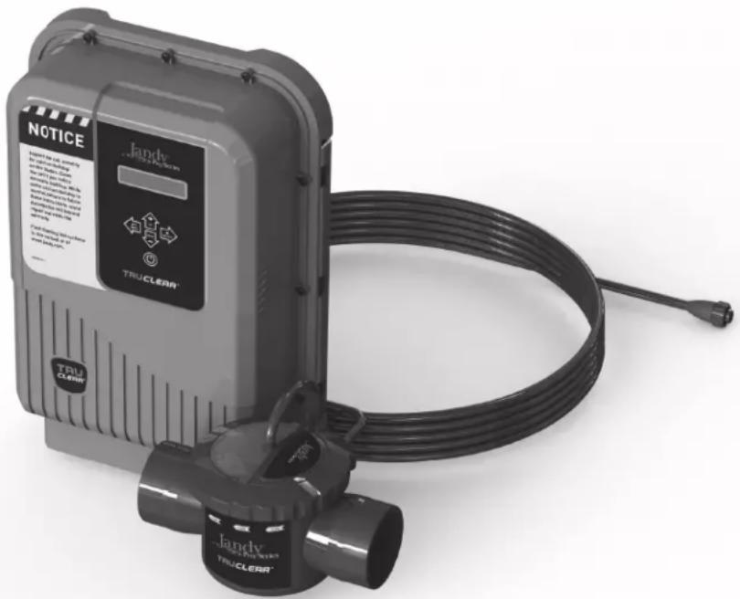
- The cell must be installed as the last piece of equipment in the circulation plumbing system just before the pool.
WARNING
This appliance is not intended for use by persons (including children) with reduced physical, sensory or mental capabilities, or lack of experience and knowledge, unless they have been given supervision or instruction concerning use of the appliance by a person responsible for their safety.
WARNING
To reduce the risk of injury, do not remove the suction fittings of your spa or hot tub. Never operate a spa or hot tub if the suction fittings are broken or missing. Never replace a suction fitting with one rated less than the flow rate marked on the equipment assembly.
WARNING
PREVENT CHILD DROWNING: Do not let anyone, especially small children, sit, step, lean or climb on any equipment installed as part of your pool's operational system. Locate the components of your operational system at least 1 m (3 ft.) from the pool so children cannot use the equipment while in the pool and be injured or drown.
WARNING
Prolonged immersion in hot water may induce hyperthermia. Hyperthermia occurs when the internal temperature of the body reaches a level several degrees above the normal body temperature of 37 ^ ( 98.6 ^ ). The symptoms of hyperthermia include dizziness, fainting, drowsiness, lethargy, and an increase in the internal temperature of the body. The effects of hyperthermia include:
• Unawareness of impending danger
- Failure to perceive heat
- Failure to recognize the need to exit spa
• Physical inability to exit spa
• Fetal damage in pregnant women
• Unconsciousness resulting in a danger of drowning
WARNING
To Reduce the Risk of Injury -
- The water in a spa should never exceed 40^ C ( 104^ F). Water temperatures between 38^ C ( 100^ F) and 40^ C ( 104^ F) are considered safe for a healthy adult. Lower water temperatures are recommended for young children and when spa use exceeds 10 minutes.
- Since excessive water temperatures have a high potential for causing fetal damage during the early months of pregnancy, pregnant or possibly pregnant women should limit spa water temperatures to 38^ (100°F).
- Before entering a spa or hot tub, the user should measure the water temperature with an accurate thermometer since the tolerance of water temperature-regulating devices varies.
- The use of alcohol, drugs, or medication before or during spa or hot tub use may lead to unconsciousness with the possibility of drowning.
- Obese persons and persons with a history of heart disease, low or high blood pressure, circulatory system problems, or diabetes should consult a physician before using a spa.
- Persons using medication should consult a physician before using a spa or hot tub since some medication may induce drowsiness while other medication may affect heart rate, blood pressure, and circulation.
WARNING
• People with infectious diseases should not use a spa or hot tub.
• To avoid injury, exercise care when entering or exiting the spa or hot tub.
- Do not use drugs or alcohol before or during the use of a spa or hot tub to avoid unconsciousness and possible drowning.
- Pregnant or possibly pregnant women should consult a physician before using a spa or hot tub.
• Water temperature in excess of 38^ C ( 100^ F) may be injurious to your health.
- Before entering a spa or hot tub measure the water temperature with an accurate thermometer.
- Do not use a spa or hot tub immediately following strenuous exercise.
- Prolonged immersion in a spa or hot tub may be injurious to your health.
- Do not permit any electric appliance (such as a light, telephone, radio, or television) within 1.5 m (5 ft.) of a spa or hot tub.
- The use of alcohol, drugs or medication can greatly increase the risk of fatal hyperthermia in hot tubs and spas.
CAUTION
This device is intended for use with permanent swimming pools and may also be used with hot tubs and spas if so marked. Do not use with storable pools or stand-alone spas. A permanently-installed pool is constructed in or on the ground or in a building such that it cannot be readily disassembled for storage. A storable pool is constructed so that it is capable of being readily disassembled for storage and reassembled to its original integrity.
CAUTION
It is important to note that certain materials used in and around swimming pools and spas may not be compatible with chemicals commonly used to purify pool and spa water (e.g. acids, chlorine, salt, stabilizers, etc.).
Zodiac Pool Systems LLC does not warrant or guarantee that the chlorinated water generated by the Jandy chlorine generating device will not damage or destroy certain types of plants, decking, coping and other materials in and around your pool and/or spa. Before selecting materials to be used in and around your pool and/or spa, please discuss all options with your contractor to assess the compatibility of such materials and chemicals.
When mixing acid or other chemicals with water, ALWAYS ADD THE ACID OR CHEMICALS TO WATER. NEVER ADD WATER TO THE ACID OR CHEMICALS.
Some helpful considerations may include:
- Choosing plants that can withstand splash out of pool water containing chlorine and/or salt and other water purification chemicals.
- All metal components used in and around a pool should be of a high grade, quality stainless steel.
- Careful selection of masonry products. The porosity and hardness of natural stones varies greatly. Therefore we recommend you consult with your builder or stone contractor on the best choice for stone materials around your pool or spa.
- Sealing all masonry products. Professionals in the stone industry specify that even natural stone, especially when used outdoors, be sealed to prevent weathering, staining, and premature degradation. Consult with your stone or deck contractor for the proper sealer for the masonry products you have selected to use around your pool or spa.
- For the optimal results, sealers should be reapplied on a regular basis. Reapply the protective sealer on a schedule per the manufacturer's instructions.
- Use of chemicals other than those recommended may be hazardous. Follow the chemical manufacturers instructions.
WARNING
To minimize risk of severe injury or death, filter, pump, and/or chlorinator should not be subjected to the piping system pressurization test.
Local codes may require the pool piping system to be subjected to a pressure test. These requirements are generally not intended to apply to the pool equipment, such as filters, pumps, or chlorinators.
Jandy pool equipment is pressure tested at the factory.
If, however, the WARNING cannot be followed and pressure testing of the piping system must include the filter, pump, and/or chlorinator, BE SURE TO COMPLY WITH THE FOLLOWING SAFETY INSTRUCTIONS:
- Remove cell and install Pressurizing, Installation and Winterizing Cap (P/N: R0621900) before testing.
- Check all clamps, bolts, lids, lock rings, and system accessories to ensure they are properly installed and secured before testing.
- RELEASE ALL AIR in the system before testing. AIR PRESSURE must NOT be used for pressure testing.
• Water pressure for test must NOT EXCEED 35 PSI.
• Water temperature for test must NOT EXCEED 100°F (38°C) - Limit test to 24 hours. After test, visually check system to be sure it is ready for operation.
Notice: These parameters apply to Jandy equipment only. For non-Jandy equipment, consult the equipment manufacturer.
Section 2. General Description
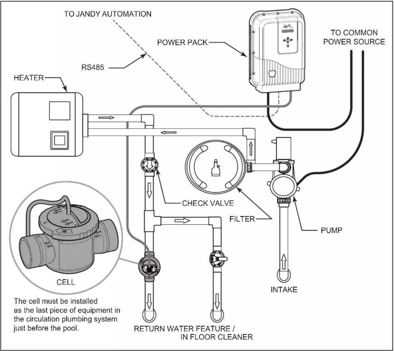
Figure 1. Example of Installation
2.1 Product Specifications
| Maximum Operating Pressure: 50 psi Input Freq: 50/60 Hz | |
| Minimum Flow Rate: 76 lpm (20 gpm) Output Voltage: 25V DC (max) | |
| Required Salt Level: 3.0 gpl (3,000 ppm) Dimensions: | |
| Maximum water volume treated:132,000 L (35,000 gal.) | Power Pack (L x W x H):25.4 cm x 11.4 cm x 33 cm (10 in. x 4.5 in. x 13 in.)Electrolytic Cell (L x W x H):16.5 cm x 14 cm x 30.5 cm (6.5 in. x 5.5 in. x 12 in.) |
| Chlorine Output: 18.4 g/hr | |
| Input Voltages: 120/240 VAC | Weight:Power Pack: 3.2 kg. (7 lbs)Electrolytic Cell: 0.9 kg (2 lbs) |
| Input Current @ 240 VAC: ~2 AInput Current @ 120 VAC: ~4 A | |
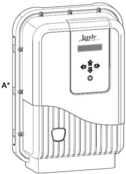
2.2 Product Contents
natural_image
Line drawing of a Jandy industrial control box with ventilation slots and control panel (no text or symbols)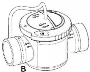
natural_image
Technical line drawing of a mechanical valve or pump component (no text or symbols)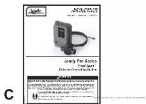
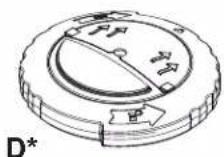
Figure 2. Carton Contents
Items Included
| ITEM | DESCRIPTION | QTY |
| A | Power Pack | 1 |
| B | Cell (Item shown is the standard cell. A version with unions is an available option) | 1 |
| C | Installation and Operation Manual | 1 |
* Items Sold Separately as Replacement Parts
| ITEM | DESCRIPTION | Part # | |
| D | Pressurizing, Installation and Winterizing Cap | R0621900 | TRUCLEAR CELL |
| not shown | TruClear Cell, Replacement (no Housing) | R0693900 | |
| not shown | TruClear Housing, Replacement (no Cell) | R0694000 | |
| not shown | TruClear O-Ring, Replacement | R0694100 | |
| not shown | O-Ring Tail Piece | R0449200 | |
| A | Power Pack | R0802200 | POWER PACK |
| not shown | TruClear11P Power Pack Cover, Replacement | R0663800 | |
| not shown | TruClear PCB, Replacement Assembly | R0802300 | |
| not shown | TruClear Cover Screw Set | R0609400 | |
| not shown | TruClear Transformer Assembly | R0802400 |
Section 3. Installation Instructions
WARNING
FOR YOUR SAFETY: This product must be installed and serviced by a professional pool/spa service technician as described on the front cover of this manual. The procedures in this manual must be followed exactly. Failure to follow warning notices and instructions may result in property damage, serious injury, or death. Improper installation and/or operation will void the warranty.
WARNING
EQUIPMENT UNDER PRESSURE: Always turn pump off prior to installing or servicing the Jandy chlorine generating device. Your pump/filter system is operated under pressure and the pressure must be released before you begin work. Please see your pump/filter owner's manual for further instructions.
Disconnect power to the system at the main circuit breaker before performing this procedure to avoid risk of electric shock which can result in property damage, severe injury or death.
Before you begin your installation, please check that you have the right tools and a suitable location to install the power pack and cell. Please ensure that you have read and understood the Important Safety Instructions section.
3.1 Materials and Tools
Tools and Materials Needed for Installation
- Screw Set (Plastic Anchors)
• Cordless Drill (or Power Drill) - 6 mm (15/64 in.) Masonry Bit or Hammer Drill Bit (only necessary to drill into brick or concrete)
- Pencil or Marking Pen
• Phillips Head Screwdriver or Phillips Head Drill Bit - WELD-ON® 724™ CPVC Gray Cement is recommended
3.2 Installation Requirements
WARNING
The cell must be installed horizontally with the cord facing upwards to avoid buildup of flammable gases which can result in FIRE OR EXPLOSION. In Canada, the Jandy chlorine generating electrolytic cell must be installed outdoors.
The installation requirements for the Jandy chlorine generating device are as follows:
- Install the power pack at least 2 feet (0.6 m) above the ground in order to protect it from pressurized water spray such as that from irrigation sprinklers, and from mechanical impacts and/or damage. Also ensure that it is inaccessible to children. Consult and comply with any and all applicable local and national installation codes and/or regulations, as may be enforced by the local Authorities Having Jurisdiction (AHJ's) or competent authority in Canada.
- In the U.S., the power pack must be installed at least 1.5 m (5 ft.) from the inside wall of your swimming pool or spa; in Canada, the power pack must be installed at least 3 m (10 ft.) from the inside wall of your swimming pool or spa.
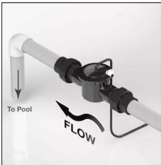
- The cell must be installed on a 0.4 m (16 in.) horizontal length of pipe after the heaters, pumps, and filters, as the last piece of equipment in the circulation plumbing system. (see Figure 3).
- The cell must be installed no more than 4.6 m (15 ft.) from the power pack (see Figure 3).
- It is recommended that the cell be installed 25 cm (10 in.) from any 90° elbow.
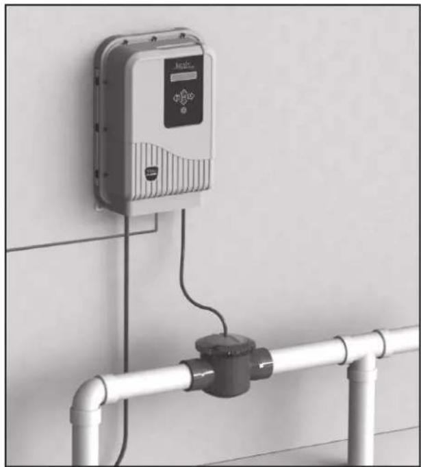
natural_image
Exterior view of a wall-mounted industrial control unit connected to a pipe with a coiled outlet (no visible text or symbols)Figure 3. Installation Requirements
3.3 Installing the Power Pack
- Ensure placement of the cell and the power pack will meet all the installation requirements outlined in Section 3.2.
- Determine the desired location on the wall to mount the Power Pack.
- Mark and drill the top two holes in the wall, using the template on the Quick Start Guide. The distance from the center of the two holes is 10". Use a level and the template to locate the exact position of the holes.
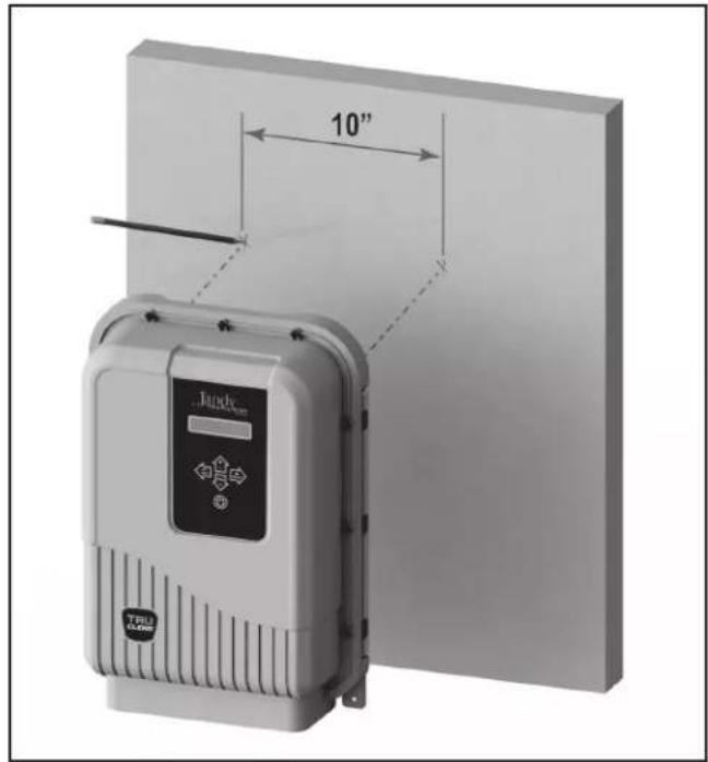
- Drive the screws into the holes and hang the Power Pack from the top two holes of the backplate.
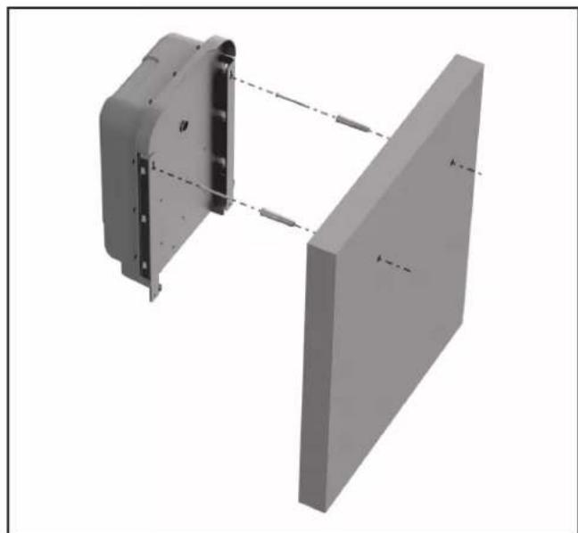
natural_image
3D mechanical assembly diagram showing two components with alignment lines (no text or symbols)- With the Power Pack in place, mark the position of the bottom two holes.
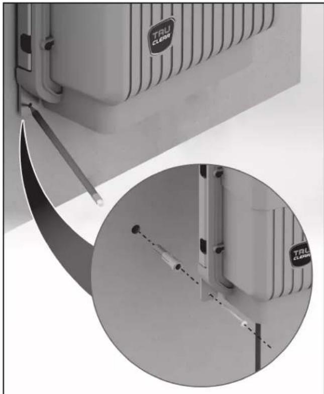
natural_image
Close-up of a TRL CLEAN appliance with a magnified inset showing internal components (no text or symbols visible)- Remove the Power Pack, drill the bottom two holes and place the screw anchors in position.
- Mount the Power Pack by hanging it from the top two screws already in place, then drive in the two bottom screws to complete the installation.
WARNING
To avoid property damage, serious injury or death, do not operate the electrolytic cell without water circulation or if cell housing is damaged or improperly assembled. A buildup of flammable gases which can result in FIRE OR EXPLOSION. The power pack must be interconnected with the pool pump motor power source to ensure that the chlorinator only operates when the pool pump is running. The flow sensor feature of the Jandy TruClear is intended to be used as a backup only and should not be used as the sole source of flow detection.
3.4 Installing the Cell
WARNING
The cell must be installed horizontally with the cord facing upwards to avoid buildup of flammable gases which can result in FIRE OR EXPLOSION. In Canada, the Jandy chlorine generating electrolytic cell must be installed outdoors.
Standard Installation
The standard installation consists of plumbing the housing unit of the TruClear directly into the pool plumbing system, without the use of threaded unions.
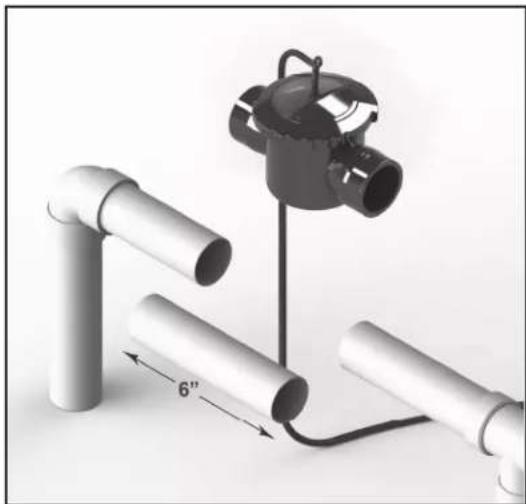
- Determine the desired location for the cell as the last piece of equipment before the return inlet to the pool, on a pipe segment at least 16 inches long. The cell must be mounted upright on pipe which runs within ±5^ of level (parallel to the ground). The cell cannot be mounted on a vertical, or sloping pipe.
NOTE The cell must be installed on a 16 Inch (40cm) horizontal length of pipe after the heaters, pumps, and filters, as the last piece of equipment in the circulation plumbing system before the pool inlet (see Figure 1).
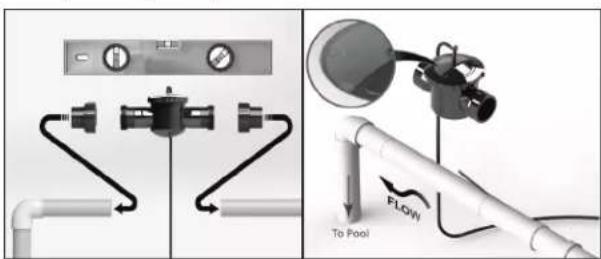
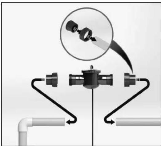
- Make the appropriate cuts in the pipe where you will be installing the cell. The gap between the cuts should be 6 inches.
natural_image
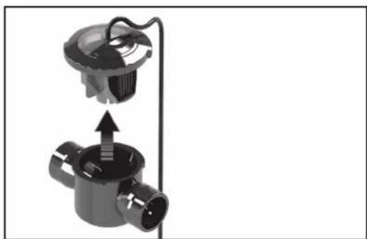
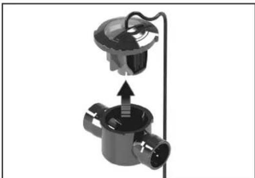
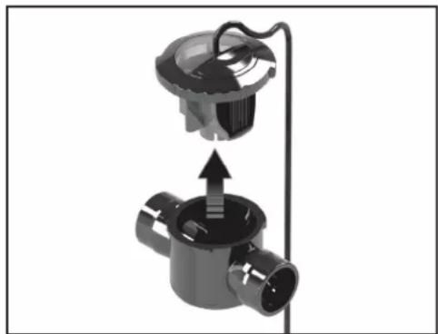
Diagram of a mechanical assembly with pipes and a clamp, showing a 6-inch length measurement between two pipes (no text or symbols present)- Remove the cell from the housing and plumb the housing into the pipe, making sure that the flow indicator arrows on the housing match the flow direction of the water. Pipes must be clean and dry before gluing.
natural_image
Mechanical assembly diagram showing a valve with internal components and an upward arrow indicating motion (no text or symbols)NOTE If the flow direction of the water does not match the arrows on the housing, the cell will malfunction.
-
Let the system dry per instructions provided by the glue manufacturer.
-
When the glue is dry, install the cell into the cell housing. Secure the cell by engaging the lock ring and ensure that the flow indication arrows on the transparent lid correspond to the arrows on the cell housing.
-
Start the system and check for proper water flow.
WARNING
To avoid property damage, serious injury or death, do not operate the electrolytic cell without water circulation or if cell housing is damaged or improperly assembled.
Retrofitted Installation
The retrofitted installation is a factory designed TruClear with threaded unions built into the housing unit. This method can be used to replace an existing chlorine generator or as a new installation.
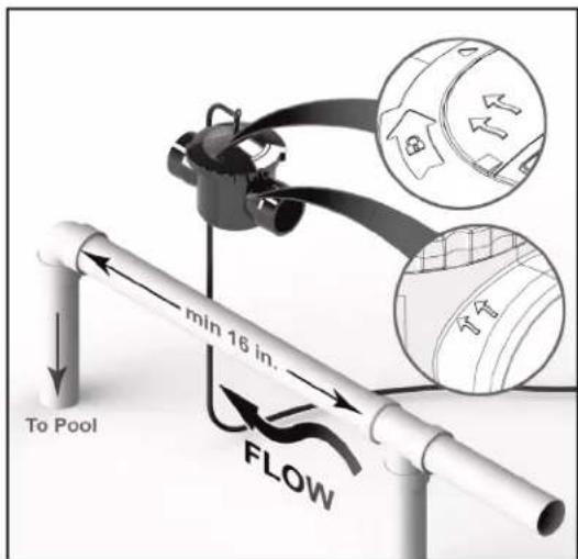
- Determine the desired location for the cell as the last piece of equipment before the return inlet to the pool, on a pipe segment at least 16 inches long. The cell must be mounted upright on pipe which runs within ± 5^ of level (parallel to the ground). The cell cannot be mounted on a vertical, or sloping pipe.
NOTE The cell must be installed on a 16 Inch (40cm) horizontal length of pipe after the heaters, pumps, and filters, as the last piece of equipment in the circulation plumbing system just before the pool (see Figure 1).
- Remove the existing equipment and make any appropriate cuts in the pipe where you will be installing the cell.
natural_image
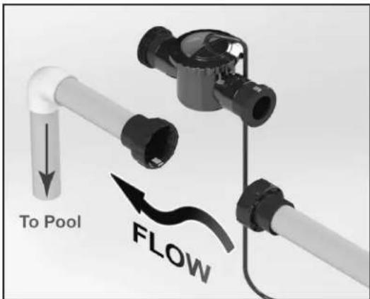
Diagram of a pipeline system with pipe flanges and a magnified inset showing a mechanical component (no text or symbols)- Remove the cell from the housing and plumb the housing into the pipe, making sure that the flow indicator arrows on the housing match the flow direction of the water. Pipes must be clean and dry before gluing.
natural_image
Mechanical assembly diagram showing a valve or connector with a central hub and internal components (no text or symbols)NOTE If the flow direction of the water does not match the arrows on the housing, the cell will malfunction.
- Let the system dry per instructions provided by the glue manufacturer. When the glue is dry, start the system and check for proper water flow. Make sure the cell is closed (locked into the housing) before you start the filter pump.
WARNING
To avoid property damage, serious injury or death, do not operate the electrolytic cell without water circulation or if cell housing is damaged or improperly assembled.
3.5 Wiring the Power Pack to the Power Source
WARNING
When using electrical products, basic precautions should always be followed, including the following:
- DANGER: RISK OF ELECTRIC SHOCK WHICH CAN RESULT IN SERIOUS INJURY OR DEATH. Before attempting installation or service, ensure that all power to the device is disconnected/turned off at the circuit breaker. Connect only to a circuit protected by a ground-fault circuit interrupter (GFCI).
- Grounding is required. The unit should be installed by a qualified service representative and should be properly grounded and bonded (See Section 3.7, Bonding).
- To avoid property damage, serious injury or death, never use the chassis backplate of the power pack to ground any other equipment.
• Install to permit access for servicing. - Select field conductor size appropriately, taking into consideration length of circuit and in accordance with applicable installation codes. Wiring should only be attempted by a qualified professional.
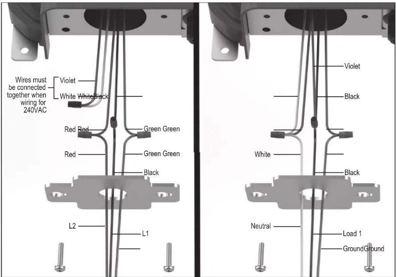
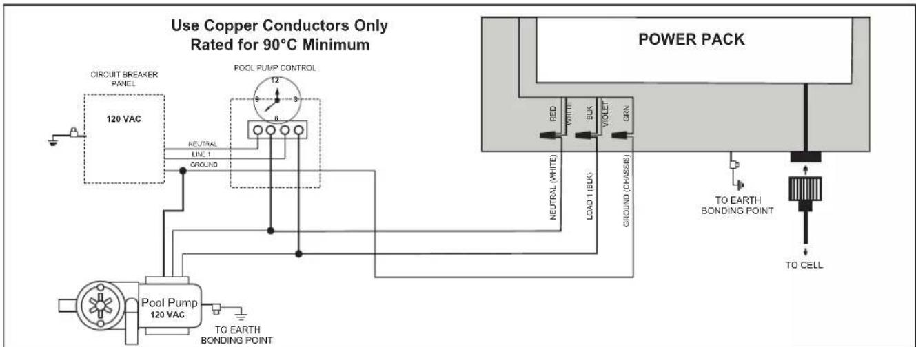
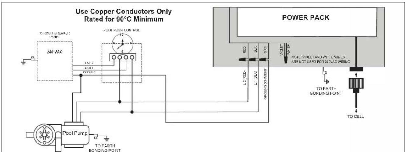
Figure 4. Wiring with a 240 VAC Filter Pump Figure 5. Wiring with a 120 VAC Filter Pump
- Wire power pack to pool pump power source using 3.3 mm^2 (12 AWG) insulated wire and conduit. Wire the power pack to the LOAD side of the filter pump or the LOAD side of the pool pump timer relay so that the chlorinator can only come on when the pool pump comes on (see Figure 4 for 240 VAC and Figure 5 for 120 VAC).
- Remove the electrical mounting plate that feeds the power cable to the power pack.
- Feed the power cable through the mounting plate.
- Connect the conduit to the mounting plate.
- Make the wire connections. Note: The green wire should be connected to the ground point. (see Figure 4 for 240 VAC and Figure 5 for 120 VAC).
- Place all of the wire connections and cables inside the power pack and secure the electrical mounting plate tightly.
WARNING
Select field conductor size appropriately, taking into consideration length of circuit and in accordance with applicable installation codes. The ground conductor must be minimum 12 AWG.
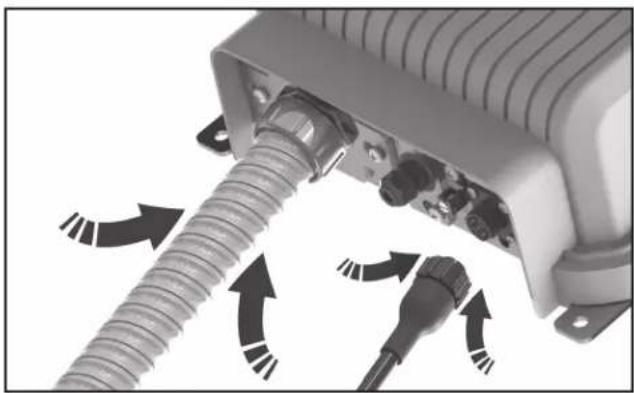
- Plug the cell into the Power Pack.
natural_image
Close-up of a mechanical device with threaded connectors and directional arrows indicating motion (no text or symbols)3.6 Install RS485 for Jandy Automation
The power pack comes equipped with a slide out RS485 connector. The RS485 connector is used to connect the Jandy TruClear chlorination system to a new or existing AquaLink® Automation System.
- Loosen DO NOT REMOVE the two screws securing the RS485 connector bracket in place. It is not required to remove the entire front cover plate.
- Slide out the 4 pin RS485 connection terminal.
-
From an open auxiliary on your automation system run the RS485 cable to the 4 pin RS485 connection terminal.
-
Unscrew cable fi tting nut, pass RS485 wires through and resecure the nut.
- Pass wires through center slot on bracket.
- Use a fl at head screwdriver to install the wires from the automation system. Match the colors to the wires already installed from the power pack.
- Once connection has been made, the User Interface (UI) should display "Standby ‡". Standby 0%
natural_image
Technical diagram showing mechanical assembly with labeled components and directional arrows (no readable text or symbols)- Follow the instructions for your automation system to continue with device set up and schedules.
- Once proper communication is confirmed, reinstall the RS485 connector bracket into the power pack body.
- If proper communication is not established begin with step 3 and retrace the above steps.
- If communication is still not established please call technical support at 800-822-7933.
NOTE The TruClear does not capture a salinity reading from your pool. When connected to an automation system, the target salinity level of 3000ppm will be displayed. "General Error" will show as a result of low salt, low temp or a combination of both.
flowchart
graph TD
    A["CIRCUIT BREAKER PANEL"] --> B["120 VAC"]
    B --> C["NEUTRAL LINE 1"]
    C --> D["POOL PUMP CONTROL"]
    D --> E["6"]
    E --> F["Pool Pump 120 VAC TO EARTH BONDING POINT"]
    F --> G["TO EARTH BONDING POINT"]
    H["POWER PACK"] --> I["RED WHITE BLK VOLET GRN"]
    I --> J["TO EARTH BONDING POINT"]
    J --> K["TO CELL"]
Figure 6. Wiring Diagram with a 120 VAC Filter Pump
flowchart
graph TD
    A["CIRCUIT BREAKER PANEL"] --> B["240 VAC"]
    B --> C["Line 2"]
    B --> D["Line 1"]
    B --> E["GROUND"]
    C --> F["Pool Pump"]
    D --> F
    E --> F
    F --> G["TO EARTH BONDING POINT"]
    H["POL PUMP CONTROL"] --> I["Ground"]
    I --> F
    J["POWER PACK"] --> K["RED"]
    J --> L["L1 (BLK)"]
    J --> M["GRN"]
    J --> N["VIOLET"]
    J --> O["WHITE"]
    J --> P["NOTE: VIOLET AND WHITE WIRESE ARE NOT USED FOR 240VAC WIRING"]
    Q["TO EARTH BONDING POINT"] --> R["TO CELL"]
Figure 7. Wiring Diagram with a 240 VAC Filter Pump
3.7 When Using In Non-automation Installations And With Jandy Variable Speed Pump
As stated in Section 3.3, the power pack must be interconnected with the pool pump motor power source to ensure that the chlorinator only operates when the pool pump is running. The Jandy TruClear chlorination system with Firmware Revision F or later, can monitor the state of the Jandy Variable Speed Pump so that the TruClear does not operate if the Jandy Variable Speed Pump is not running.
The power pack comes equipped with a slide out RS485 connector. The RS485 connector is used to connect the Jandy TruClear chlorination system to a new or existing Jandy Variable Speed Pump.
- Loosen DO NOT REMOVE the two screws securing the RS485 connector bracket in place. It is not required to remove the entire front cover plate.
- Slide out the 4 pin RS485 connection terminal.
- From the Jandy Variable Speed Pump run a parallel (to the existing controller) RS485 cable to the 4 pin RS485 connection terminal.
- Unscrew cable fi tting nut, pass RS485 wires through and resecure the nut.
- Pass wires through center slot on bracket.
-
Use a fl at head screwdriver to install the wires from the Jandy Variable Speed Pump. Match the colors to the wires already installed from the power pack.
-
Once connection has been made, the User Interface (UI) should display "Standby #".

natural_image
Technical diagram of a mechanical assembly with labeled components and directional arrows (no readable text or symbols)-
Once proper communication is confirmed, reinstall the RS485 connector bracket into the power pack body.
-
If proper communication is not established, begin with step 3 and retrace the above steps.
-
If communication is still not established, please call technical support at 800-822-7933.
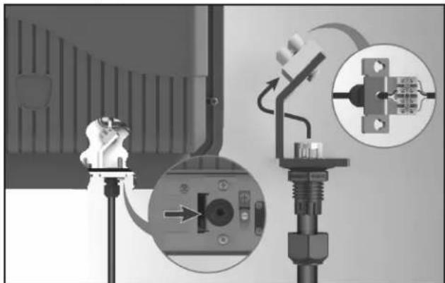
3.8 Bonding
The National Electrical Code ^® (NEC ^® in the United States) or the Canadian Electrical Code (CEC in Canada) requires pool equipment to be bonded to each other. Check your local codes to determine if the NEC or CEC and/or other local installation codes are enforced by the Authority Having Jurisdiction (AHJ in the United States) or the local competent authorities in Canada. A solid, copper 8.37 mm ^2 (8 AWG) wire is recommended, per the NEC and 13.3 mm ^2 (6 AWG) per the CEC, for bonding the power pack to a permanent bonding connection that is acceptable to the local AHJ or the local competent authorities in Canada.
Refer to your locally enforced codes for the acceptable bonding wire gauge. Attach the bonding point located on the bottom of the chassis backplate to a common bonding point. Do not use the power pack as the common bonding point. Each piece of non-related pool equipment requiring a ground should also be bonded to the common, approved bonding point. There should be one bonding connection to the power pack. In Canada, the Canadian Electrical Code (CEC) dictates that the bonding conductor be, minimum 13.3 mm ^2 (6 AWG). National Electrical Code® (NEC®) requires bonding of the Pool Water. Where none of the bonded pool equipment, structures, or parts are in direct connection with the pool water; the pool water shall be in direct contact with an approved corrosion-resistant conductive surface that exposes not less than 5800 mm ^2 (9 in ^2 ) of the surface area to the pool water at all times. The conductive surface shall be located where it is not exposed to physical damage or dislodgement during usual pool activities, and it shall be bonded in accordance with the bonding requirements of NEC Article 680. Refer to your locally enforced codes for any additional bonding requirements.
3.9 Split Return Plumbing Instructions: For Infloor Cleaning Systems
If the chlorinator is used with an in-floor cleaning system, it must be installed in a separate dedicated return line or damage to the chlorinator will occur.
NOTE Do not install the chlorinator on in-floor systems that do not have a dedicated pool return as shown in Figure 8.
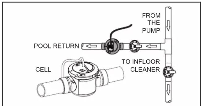
Figure 8. New Pool Plumbing for In-Floor Systems
Section 4. Pool Water Preparation

ATTENTION INSTALLER, PLEASE CHECK WATER CHEMISTRY PRIOR TO OPERATION
Please take a moment to test the water for Total Hardness (TH) before proceeding.
- Remove Test Strip from foil pouch. Take care not to put wet fingers into the foil.
- Immerse at a depth of 6" (15 cm) for 2 seconds. If testing in a spa make sure the jets are off.
- Remove with pad face up.
- Shake once to remove excess water.
- Wait 10 seconds
- Compare test strip color to the printed color chart in your test strip packet.
An ideal range is from 200 to 400. If your TH measures 800+ you must adjust water chemistry before operating the cell. Poor water chemistry will lead to rapid calcification and failure of the electrolytic cell.
4.1 Determining Pool Size (Litres)
- Rectangular Pools
Length (metres) x width (metres) x average depth (metres) x 1000 = litres capacity. - Circular Pools
Radius (metres) x Radius (metres) x 3.14 x average depth (metres) x 1000 = litres capacity.
NOTE On initial startup of a pool, it is best to shock using an alternate source, i.e., use a shock treatment available at your local pool supplier.
- Oval Pools
Short Radius (metres) x long radius (metres) x 3.14 x average depth (metres) x 1000 = litres capacity.
4.2 Determining Pool Size (Gallons)
- Rectangular Pools
Length (feet) x width (feet) x average depth (feet) x 7.5 = gallon capacity. - Circular Pools
Radius (feet) x radius (feet) x 3.14 x average depth (feet) x 7.5 = gallon capacity. - Oval Pools
Long radius (feet) x short radius (feet) x 3.14 x average depth (feet) x 7.5 = gallon capacity.
4.3 Chemistry You Need to Know
- Chlorine Stabilizer (cyanuric acid) is needed to maintain proper levels of chlorine. Most non-stabilized chlorine is destroyed by the UV radiation from the sun within two (2) hours. Chlorine stabilizer should be maintained between 30 - 50 ppm. For indoor pools, it is not necessary to add chlorine stabilizer to the swimming pool water.
- Nitrates can cause extremely high chlorine demands and will deplete chlorine from your swimming pool. In some cases nitrates may even lower your chlorine levels to zero. Your local pool professional can test for nitrates. Make sure nitrates are not present.
- Metals (some metals) can cause loss of chlorine and stain your pool. Have a local pool professional check for metals and recommend methods of removal.
- Combined Chlorine (Chloramines) should not be present in pool water. When organic materials combine with free chlorine, chloramines are formed. This ties up the free chlorine in your pool and does not allow the chlorine in your pool to disinfect. Chloramines also cloud pool water and burn the eyes. Shock to remove chloramines at the initial startup of the pool.
- Shocking or Super Chlorination enhances chlorine's ability to oxidize organic waste by eliminating combined chlorine (CC). To measure combined chlorine (CC), subtract the Free Chlorine (FC) from the Total Chlorine (TC). (TC - FC = CC).
To determine how much shock (fast dissolving chlorine) it will take to properly shock your pool, you'll need to calculate the Breakpoint Chlorine (BPC) level. To determine the Breakpoint Chlorine (BPC) needed, multiply the Combined Chlorine (CC) level by 10. Then, subtract the Free Chlorine (FC) level.
Breakpoint Chlorine (BPC) = ((CC X10) - FC) for example: If FC=1.0ppm, and if CC=0.7ppm, the BPC level would be 6.0 ppm. formula: ((0.7x10) - 1.0)=6.0
Your local pool professional can help with this calculation or can supply you with test kits that can provide this information. Running your unit at 100% for 24 hours may also help you achieve breakpoint chlorination. If diminished water clarity or evidence of algae persists, your local pool dealer may suggest additional steps to sanitize your pool water and eliminate chloramines.
Proper Water Balance is key to your enjoyment of your pool or spa experience and to the long life of your cell.
- The pH of your pool or spa's water is the measure of whether water is either acidic or scale forming. Cold water is typically more acidic, while hot water is more scale forming. The ideal range for pH in either a pool or a spa is 7.4 to 7.6 regardless of temperature. If pH is allowed to rise, above 7.6 and the chlorine generator is operating, calcium in the water may coat the metal plates in the cell. This could restrict the flow of water resulting in reduced efficiency and possibly damage the cell. If the pH is allowed to drop below 7.4, the water will become more acidic and will dissolve the metal components in the pool plumbing with the metal plates in the cell being a prime target.
- Total Dissolved Solids (TDS). Adding salt to pool water will raise the TDS level. While this does not adversely affect the pool water chemistry or clarity, the pool water professional testing for TDS must be made aware salt has been added for the sanitizing system. The individual performing the TDS test will then subtract the salinity level to arrive at the correct TDS level.
- New pool water in a recently filled or newly refinished pool may contain undesirable matter which could interfere with the salt water chlorinator's ability to sanitize properly. Make sure the water is tested by a pool professional and properly balanced before turning on the chlorinator system. New plaster pools have a constant acid demand for six (6) months. Test often and maintain a proper pH to avoid excess scaling of the cell.
- Langelier Saturation Index is a standard method of determining the potential of your pool water to be corrosive or scale forming. PH, Total Alkalinity (TA), temperature, Calcium Hardness and Total Dissolved Solids (TDS) play a role in the calculation of the final saturation rating.
NOTE On initial startup of a pool, it is best to shock using an alternate source, i.e., use a shock treatment available at your local pool supplier.
| Saturation Index = pH + AF + CF + TF -12.1*A-Factor=(AF), C-Factor=(CF), T-Factor=(TF) | |||||
| Total Alkalinity | Calcium Hardness Temperature | ||||
| A-Factor C-Factor T-Factor | |||||
| PPM | Factor Value | PPM | Factor Value | °F | Factor Value |
| 5 = 0.7 5 = 0.9 32 | = 0.0 | ||||
| 25 = 1.4 25 = 1.0 | 37 = 0.1 | ||||
| 50 = 1.7 50 = 1.3 | 46 = 0.2 | ||||
| 75 = 1.9 75 = 1.5 | 53 = 0.3 | ||||
| 100 = 2.0 100 = 1 | 6 60 = 0.4 | ||||
| 150 = 2.2 150 = 1 | 8 66 = 0.5 | ||||
| 200 = 2.3 200 = 1 | 9 76 = 0.6 | ||||
| 300 = 2.5 300 = 2 | 1 84 = 0.7 | ||||
| 400 = 2.6 400 = 2 | 2 94 = 0.8 | ||||
| 800 = 2.9 800 = 2 | 5 105 = 0.9 | ||||
| A saturation index of 0 is perfectly balancedA negative saturation index has corrosive tendenciesA positive saturation index has scaling tendenciesA saturation index of +0.3 or -0.3 is ideal*-12.1 should be changed to -12.2 if Total Dissolved Solids (TDS) measure at 1,000 ppm or greater | |||||
4.4 Optimum Pool Water Conditions
In accordance with the Association of Pool and Spa Professionals ^® (APSP ^® ) standards, we recommend the following water balance conditions be maintained on an on-going basis to protect the pool finish and the equipment and to ensure the pleasing appearance of the water. The Jandy TruClear is warranted to operate properly only if the following conditions are met:
Free Chlorine: Ideal levels should be 1.0 - 3.0 ppm.
Combined Chlorine (Chloramines): None. Use shock (fast dissolving chlorine to remove all chloramines).
pH: 7.4 - 7.6 (Use muriatic acid to lower pH and soda ash to raise pH).
Chlorine Stabilizer (Cyanuric Acid): 30 - 50 ppm (for outdoor pools only).
Total Alkalinity: 80 - 120 ppm (U.S.); 100 - 120 ppm (Canada)
Calcium Hardness: 200 - 400 ppm
Metals (Iron, Manganese): None
Nitrates: None
Phosphates: None
Temperature: Above 60°F (16°C)
4.5 Collecting a Water Sample
To properly collect a water sample for use with your home test kit or to be taken to local pool dealer there are some good practice suggestions that should be followed.
- Never use glass containers in the pool area.
- Choose a location well away from the return fittings that are bringing water back to the pool.
- Take the container and turn it upside down to trap air and then turn the container upright 46 cm (18 in.) below the surface of the water. Bring container to the surface and cap the container.
4.6 Salt (NaCl Sodium Chloride)
When to add salt
Add salt to the pool if the salt is too low (see Table 1). For a new pool or newly resurfaced pool it is recommended to wait at least 30 days (surface should be completely cured) before adding salt. Do not run the chlorinator at this time. Manually chlorinate the pool. Contact your dealer for recommendations. Follow the pool surface manufacturer's guidelines for your particular pool. For vinyl and fiberglass pools, salt can be added at start up.
What Type of Salt to Use
- The purer the salt, the better the life and performance of the electrolytic cell. Use a salt that is at least 99.8% pure NaCl. The salt is an evaporated, granulated, food quality, non-iodized salt. Consult your pool store.
-
Avoid using salt with anti-caking agents (sodium ferrocyanide, also known as YPS or yellow prussiate of soda) that could cause some discoloration of fittings and surface finishes in pool.
-
Water conditioning salt pellets are compressed forms of evaporated salt and may be used but will take longer to dissolve.
- Do not use calcium chloride as a source of salt. Use sodium chloride only.
- Do not use rock salt because insoluble impurities mixed with the rock salt can shorten the life of the unit.
How Much Salt to Use
Use salinity test strips, a TDS/salinity meter, or another reliable method to test the salinity of the pool water. Once the existing salinity has been established, use Table 1 to determine the amount of salt to add to reach the desired level. Be conservative when adding salt as it is easier to add more if needed than it is to dilute if there is too much salt.
- 3,000 ppm of salt is recommended for optimum water conditions.
- Low salt concentration below 2,500 ppm will cause premature cell failure.
- High salt concentration above 6,000 ppm may cause corrosion damage to pool fixtures.
How to Add Salt to the Pool
- Turn on pump to circulate pool water.
- IMPORTANT - Turn the power pack off by pressing and holding the ON/Off button for 6 seconds.
- Test the water for salinity level using test strips, electronic meter, or by your local pool professional.
CAUTION
It is important to note that certain materials used in and around swimming pools and spas may not be compatible with chemicals commonly used to purify pool and spa water (e.g. acids, chlorine, salt, stabilizers, etc.).
Zodiac Pool Systems LLC does not warrant or guarantee that the chlorinated water generated by the Jandy chlorine generating device will not damage or destroy certain types of plants, decking, coping and other materials in and around your pool and/or spa. Before selecting materials to be used in and around your pool and/or spa, please discuss all options with your contractor to assess the compatibility of such materials and chemicals. When mixing acid with water, ALWAYS ADD ACID TO WATER. NEVER ADD WATER TO ACID.
Some helpful considerations may include:
- Choosing plants that can withstand splash out of pool water containing chlorine and/or salt and other water purification chemicals.
- All metal components used in and around a pool should be of a high grade, quality stainless steel.
- Careful selection of masonry products. The porosity and hardness of natural stones varies greatly. Therefore we recommend you consult with your builder or stone contractor on the best choice for stone materials around your pool or spa.
- Sealing all masonry products. Professionals in the stone industry specify that even natural stone, especially when used outdoors, be sealed to prevent weathering, staining, and premature degradation. Consult with your stone or deck contractor for the proper sealer for the masonry products you have selected to use around your pool or spa.
- For optimal results, sealers should be reapplied on a regular basis. Reapply the protective sealer on a schedule per the manufacturer's instructions.
-
Use of chemicals other than those recommended may be hazardous. Follow the chemical manufacturers instructions.
-
Use the Table 1 to determine the amount of salt to add. Be conservative when adding salt as it is easier to add more if needed than it is to dilute if there is too much salt.
- Disperse salt into pool. Do not add through skimmer, main drain, or surge tank. Brush the salt around the pool to facilitate dissolving. Circulate filter system for 24 hours to ensure even distribution.
- After 48-72 hours, verify correct salt reading by testing the water salinity level using test strips, electronic meter, or by your local pool professional.
- When the salinity level is correct, turn the power pack on. Press the ↑ buttons to set the desired production rate.
NOTE For a new pool or newly resurfaced pool it is recommended to wait at least 30 days (surface should be completely cured) before adding salt. Follow the pool surface manufacturers guidelines for your particular pool. For vinyl and fiberglass pools, salt can be added at start up.
Table 1. Approximate Pounds and Kilograms of Salt Needed to Obtain 3.0 gpl (3,000 ppm)
| Current Salt Level ppm | Pool/Spa Size - US Gallons (Litres) | |||||||||
| 10,000 gal 15,000 gal 20,000 gal 25,000 gal 30,000 gal 35,000 gal(38,000 L) (57,000 L) (76,000 L) (95,000 L) (114,000 L) (132,000 L) | ||||||||||
| 0 | 250 lbs (114 kgs) | 376 lbs (170 kgs) | 501 lbs (227 kgs) | 626 lbs (284 kgs) | 751 lbs (341 kgs) | 876 lbs (397 kgs) | ||||
| 250 | 229 lbs (104 kgs) | 344 lbs (156 kgs) | 459 lbs (208 kgs) | 574 lbs (260 kgs) | 688 lbs (312 kgs) | 803 lbs (364 kgs) | ||||
| 500 | 209 lbs (95 kgs) | 313 lbs (142 kgs) | 417 lbs (189 kgs) | 522 lbs (237 kgs) | 626 lbs (284 kgs) | 730 lbs (331 kgs) | ||||
| 750 | 188 lbs (85 kgs) | 282 lbs (128 kgs) | 376 lbs (170 kgs) | 469 lbs (213 kgs) | 563 lbs (256 kgs) | 657 lbs (298 kgs) | ||||
| 1000 | 167 lbs (76 kgs) | 250 lbs (114 kgs) | 334 lbs (151 kgs) | 417 lbs (189 kgs) | 501 lbs (227 kgs) | 584 lbs (265 kgs) | ||||
| 1250 | 146 lbs (66 kgs) | 219 lbs (99 kgs) | 292 lbs (132 kgs) | 365 lbs (166 kgs) | 438 lbs (199 kgs) | 511 lbs (232 kgs) | ||||
| 1500 | 125 lbs (57 kgs) | 188 lbs (85 kgs) | 250 lbs (114 kgs) | 313 lbs (142 kgs) | 376 lbs (170 kgs) | 438 lbs (199 kgs) | ||||
| 1750 | 104 lbs (47 kgs) | 156 lbs (71 kgs) | 209 lbs (95 kgs) | 261 lbs (118 kgs) | 313 lbs (142 kgs) | 365 lbs (166 kgs) | ||||
| 2000 | 83 lbs (38 kgs) | 125 lbs (57 kgs) | 167 lbs (76 kgs) | 209 lbs (95 kgs) | 250 lbs (114 kgs) | 292 lbs (132 kgs) | ||||
| 2250 | 63 lbs (28 kgs) | 94 lbs (43 kgs) | 125 lbs (57 kgs) | 156 lbs (71 kgs) | 188 lbs (85 kgs) | 219 lbs (99 kgs) | ||||
| 2500 | 42 lbs (19 kgs) | 63 lbs (28 kgs) | 83 lbs (38 kgs) | 104 lbs (47 kgs) | 125 lbs (57 kgs) | 146 lbs (66 kgs) | ||||
| 2750 | 21 lbs (9 kgs) | 31 lbs (14 kgs) | 42 lbs (19 kgs) | 52 lbs (24 kgs) | 63 lbs (28 kgs) | 73 lbs (33 kgs) | ||||
| 3000 | Optimum | Optimum | Optimum | Optimum | Optimum | Optimum | ||||
Table 2. Approximate Pounds and Kilograms of Stabilizer Needed to Obtain 50 ppm
| Current Cyanuric Acid Level - ppm | Pool/Spa Size US Gallons (Litres) | ||||||||||
| 10,000 gal | (38,000 L) | 15,000 gal | (57,000 L) | 20,000 gal | (76,000 L) | 25,000 gal | (95,000 L) | 30,000 gal | (114,000 L) | 35,000 gal | |
| 0 | (4.2 lbs) | 1.9 kgs | (6.3 lbs) | 2.9 kgs | (8.4 lbs) | 3.8 kgs | (10.5 lbs) | 4.8 kgs | (12.6 lbs) | 5.7 kgs | (14.8 lbs) |
| 10 | (3.4 lbs) | 1.5 kgs | (5.1 lbs) | 2.3 kgs | (6.7 lbs) | 3.1 kgs | (8.4 lbs) | 3.8 kgs | (10.1 lbs) | 4.6 kgs | (11.8 lbs) |
| 20 | (2.5 lbs) | 1.1 kgs | (3.8 lbs) | 1.7 kgs | (5.1 lbs) | 2.3 kgs | (6.3 lbs) | 2.9 kgs | (7.6 lbs) | 3.4 kgs | (8.9 lbs) |
| 30 | (1.7 lbs) | 0.8 kgs | (2.5 lbs) | 1.2 kgs | (3.4 lbs) | 1.5 kgs | (4.2 lbs) | 1.9 kgs | (5.1 lbs) | 2.3 kgs | (5.9 lbs) |
| 40 | (0.8 lbs) | 0.4 kgs | (1.3 lbs) | 0.6 kgs | (1.7 lbs) | 0.8 kgs | (2.1 lbs) | 1.0 kgs | (2.5 lbs) | 1.2 kgs | (3.0 lbs) |
NOTE For indoor pools, it is not necessary to add chlorine stabilizer to the swimming pool water.
Section 5. Operating Instructions
5.1 Turning Power Pack On/Off (Manually)
To turn the Jandy chlorine generating device on or off press the ⏻ button.
A quick press will place the chlorinator into “standby” state. While in “standby” mode a quick press will return to “chlorinating” mode. If held down for 6 seconds it will completely power down.
NOTE Because the power pack is wired to the pump's power source, the power pack can only be turned on when the pump is turned on.
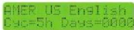
5.2 Select Language
Press and hold the buttons simultaneously for five seconds to access the service menu. Use the ⚠ button to select language. Press the ⚣ button to exit when your selection has been made.
5.3 Turning Power Pack On/Off (Using the Pump's External Timer)
If the power pack is wired to the pump's external timer and the power to the unit is on, the power pack will automatically turn on and off when the pump turns on and off (see Section 3.5). When the power pack is wired as such, the only setting that must be set manually is the chlorine output level (see Section 5.4).
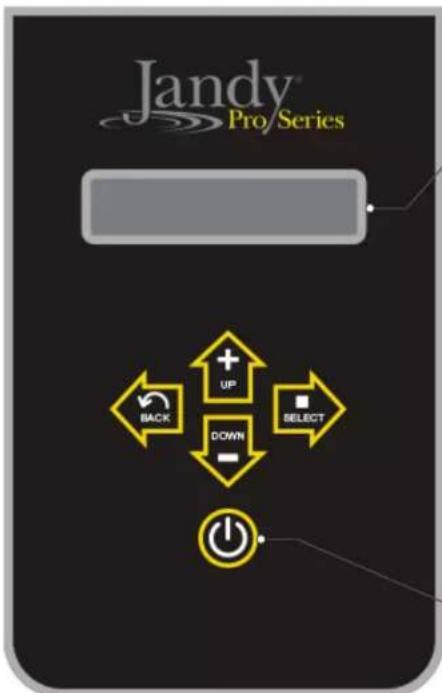
• DISPLAY
Shows TruClear™ status and chlorine production percentage.

Indicates TruClear is in standby mode and will not be producing chlorine even if the filter pump is running.

Indicates TruClear has detected filter pump activation and is initiating chlorine production.

Indicates TruClear is currently producing chlorine and displays current production output percentage.

Indicates TruClear is connected to a remote automation system via RS485*.
Press to turn power to system on. Press and hold for 6 seconds to completely power the system down. A single quick press will toggle the system from Standby to Auto mode when not connected to a remote automation system via RS485*.

In normal operation, the up and down arrows are used to set the output level of the chlorinator. The output should be adjusted in order to achieve the desired Free Available Chlorine level of 2-4 ppm.

The back/save button will save any changes you have made in the menu and send you back to the previous menu screen. The select button will scroll through and open any available parameters for editing.
*When connected to an automation system via RS485, full control of the TruClear system is given over to the automation controller. No functionality will persist at the TruClear UI. In order to control the TruClear from the UI, the automation system must first be placed into service mode. For details on service mode please consult the operation manual for the controller you are using as follows:
- AquaLink®RS: 6594 • Z4: H0386500 • PDA: H0572300
5.4 Chlorine Output Level
When setting the chlorine output level, the factors to consider are:
- number of gallons in the pool
- number of bathers (bather load)
- amount of pollen and dust going in the water
- number of hours the pump runs
- whether you are using a single or variable speed pump
- climate and water temperature
- amount of rain water entering the pool.
A good starting point for pools at 15K gallons and under should be 40%. Pools closer to the 25K to 30K gallons should use 60% as a starting point.
If you find that these levels do not provide the 1 - 3 PPM chlorine residual that is desired, then raise the output level higher to compensate.
If you find that output level is approaching 90% to 100% and testing the pool water shows no or very low chlorine residual, your pool may need to be manually shocked due to a waste load that has built up in the pool water that is overwhelming the chlorine you are supplying to the pool. Another cause may be the lack of Cyanuric Acid (CYA) at appropriate levels to protect the chlorine from the UV rays of the sun.
NOTE The unit only runs while your pump is running. More pump runtime will result with more chlorine in the water.
With all the variables mentioned above, it may take you a couple weeks to find the right production rate for your pool. To adjust the output level, follow these steps:
-
Turn the power pack on by pressing the button.
-
Press the buttons to reach the desired output level. The minimum setting is 10%. The output can be adjusted in increments of 10% up to 100%. This controls the amount of run time for the cell.
CAUTION
Never use dry acid to adjust pH in arid geographic areas with excessive evaporation and minimal dilution of pool water with fresh water. A build up of by products can damage the electrolytic cell.
IMPORTANT Always test the chlorine levels of your pool before each use. During heavy usage where bather load is increased, chlorine levels may deplete quickly and require more adjustments. Monitor the chlorine closely, and take appropriate measures in order to maintain the recommended 1 - 3 ppm free chlorine residual.
![If your Total Hardness (TH)* level is above 400 ppm or you reside in an area known to have hard water, it is recommended you change the polarity reversal time from the default of 5 hours to every 3 hours (instructions on back). Areas known to have hard water *Three [3] Total Hardness (TH) test strips are included To change the polarity reversal time from the default of 5 hours to the recommended 3 hours, press the up and down arrows simultaneously to access the service menu. Regular inspection and cleaning is the best way to extend the life of the chlorinator. Check cell weekly for scale formation; if you need to clean the cell more than once a month, it is also recommended you change the polarity reversal time to every 3 hours. Please contact Customer Service at (800) 822-7933 with any additional questions. ©2020 Zodiac Pool Systems LLC. All rights reserved. ZODIAC® is a registered trademark of Zodiac International D.A.S.U. used under license. All other trademarks are the property of their respective owners.](/content/2026/04/648316/images/9ed57f948280bbf105b07f7d92bb23698f7bbcb28919fb002a76c18eac7aa73a.jpg)
Figure 9. Total Hardness (United States)
5.5 BOOST/LOW Mode
The BOOST mode can be used to maximize chlorine output for a short period of time. To activate BOOST mode, press the 🔒 and buttons simultaneously. The boost will turn off after 24 hours. To turn off BOOST mode manually, press the button.
The LOW mode can be used to minimize chlorine output while activated. To activate LOW mode, press the ▼ and ➡ buttons simultaneously. The LOW mode will stay on indefinitely. To turn off LOW mode, press the ➡ button
5.6 Polarity Reversal
The Jandy chlorine generating device is a reversible polarity cell which means that the cell will periodically switch its polarity to help prevent any build up of calcium on the cell plates. This is sometimes referred to as the automated cell cleaning feature. During the transition between changing its polarity there is a brief period when the cell will not produce any chlorine. Once it has changed polarity, it will continue to make chlorine. In areas of hard water (See map in Figure 9). It is recommended that you manually adjust the polarity reversal time from 5 hours to three hours. To make the change, press and hold the up and down arrows simultaneously to enter the service mode. See Figure 9. Press the right arrow key once to select “Cyc=”. Use the button to cycle between three, fi ve and seven hour cycles. Press the button to exit.
NOTE 'CLEANING' will be displayed on the screen during the 'WAIT' period. The output level indicator will remain as set during the cleaning period.
If your Total Hardness (TH)\* level is above
400 ppm or you reside in an area known to have hard water, it is recommended you change the polarity reversal time from the default of 5 hours to every 3 hours (instructions on back).

natural_image
Map outline of a geographic region with labeled states and shaded areas (no text or labels)
Areas known to have hard water
*Three (3) Total Hardness (TH) test strips are included
Figure 10. Hard Water Map (Canada)
Section 6. Maintenance
Before servicing the Jandy chlorine generating device, ensure that you have read and understood the Important Safety Instructions section.
6.1 Weekly
- Chlorine Test. Test pool water chlorine level with a reliable test kit. Maintain an ideal range by adjusting the chlorine output level on the power pack (see Section 5.4) or if necessary, by supplementing the chlorinator with additional dry or liquid chlorine. The recommended free chlorine level is 1 - 3 ppm. See section 4.5 for instructions on collecting a water sample.
NOTE Never use glass containers in the pool area. Broken glass becomes difficult to see under water.
- pH Level Test. Test the pH level of your pool with a test kit. If necessary, adjust to maintain a pH level of 7.4 - 7.6 (see Section 4.3).
- Total Alkalinity Test. Test pool water for total alkalinity with a test kit. Take steps necessary to maintain an alkalinity of 80 - 120 ppm (U.S.) or 100 - 120 ppm (Canada) (see Section 4.3).
- Calcium Hardness. Test pool water for calcium hardness level using test kit or by having a water sample tested by a pool professional. Adjust as necessary to maintain a calcium hardness of 175 - 400 ppm (see section 4.3).
6.2 Monthly
- Check the cell. It is recommended that the cell be inspected every month for scale and/or calcium deposits. Light colored, crusty deposits known as scale will form in excessively hard water or from pool water that is out of balance. Following the installation of the Jandy chlorine generating device, check the cell once a month for signs of scale. Hold the plate bundle to a light source so the light can be seen between the plates. If the light is easily seen through the plates and/or a small amount of scale is visible, the cell does not need to be cleaned. Reinstall.
On the other hand, if the light is barely visible through the plates or the light is totally blocked by scale, then the cell needs to be cleaned. See Section 6.3 for instructions.
NOTE Excessive cleaning can shorten the life of your cell.
- Salt Level Test. Use salinity test strips, a TDS/salinity meter, or another reliable method to test the salinity of the pool water. Once the existing salinity has been established, use Table 1 to determine the amount of salt to add to reach the desired level. Be conservative when adding salt as it is easier to add more if needed than it is to dilute if there is too much salt. If the salinity level of the pool is correct and the salt LED does not go out, see Section 7. Troubleshooting.
- Pool Water Sample. Take water sample to local pool store for testing.
- Stabilizer (Cyanuric Acid). Test pool water stabilizer (cyanuric acid) level using a test kit or by having a water sample tested by a pool professional. Maintain ideal range of 30 - 50 ppm. Follow your pool professional's recommendations and check all local and federal regulations to ensure that the ideal range is suitable for your specific conditions. For indoor pools, it is not necessary to add chlorine stabilizer to the swimming pool water.
- Metals Test. It is recommended that the pool water be tested periodically for the presence of metals such as iron, and manganese. These metals should not be present in the pool water. If those metals are present, contact your local pool professional.
6.3 Cleaning the Cell
CAUTION
Disconnect power to the system at the main circuit breaker before performing this procedure to avoid risk of electric shock which can result in property damage, severe injury or death.
If the cell has a tendency to scale, it is recommended that every month the cell be removed and inspected for scale formation and/or debris. Some filters allow debris to pass through to the cell which could lodge between the plates in the cell. A small amount of scale formation is normal. If by looking through the cell it is observed that there is excessive scale formation between the plates or debris is present, the cell must be cleaned as follows:
natural_image
Mechanical assembly diagram showing a valve with internal components and an upward arrow indicating motion (no text or symbols)- Ensure that all power to the power pack and the controller is turned off at the circuit breaker.
- Before removing the cell for cleaning, shut off any necessary valves to prevent any water loss.
- Open the air relief valve on the filter to release any pressure in the pool system.
- Loosen the ring and remove the cell.
- With protective glasses and gloves on, add one (1) part muriatic acid to ten (10) parts water in a small bucket and mix the cleaning solution together.
CAUTION
- When cleaning the cell, wear protective eyeglasses and gloves.
- When mixing acid with water, prepare the solution by ALWAYS ADDING ACID TO WATER. NEVER ADD WATER TO ACID.
-
Never use undiluted Muriatic acid. Always use the recommended mixture of Muriatic acid and water.
-
Submerge the cell into the cleaning solution.
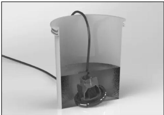
natural_image
Exterior view of a cylindrical container with a coiled cable and a submerged mechanical component (no text or symbols visible)- A foaming action will begin, which is caused by scale (calcium carbonate) being dissolved from the plates. If foaming action does not begin, the cell does not need to be cleaned (STOP THE CLEANING PROCESS - go to the step 10). Otherwise allow the cell to remain in the solution until the foaming has stopped (approximately 5 - 10 minutes).
NOTE Do not use a screwdriver or any other metal object to remove calcium deposits.
-
Flush the cell with fresh water and perform the inspection again. If considerable blockage is still present, then re-submerge the plates back into the cleaning solution, flush and reinspect.
-
After the cell has been cleaned, dispose of the solution according to local regulations.
-
Rinse the cell thoroughly with clean tap water and inspect. If deposits are still visible on the electrolytic cell, repeat step 6.
NOTE Excessive acid washing will damage the electrolytic cell. Do not leave in acid for more than 30 minutes.
- Once the cell is clean, reattach the cell as described in Section 3.4.
WARNING
Do not energize or operate the unit if the cell housing is damaged or improperly assembled.
6.4 Winterizing
NOTE Do not use Ethylene Glycol (anti-freeze) in the system.
Very little chlorine is needed in cold water. Operating the chlorinator below 55^ F ( 13^ C) is not recommended. Operating the chlorinator in cold water can dramatically shorten the life of the cell.
If preventative measures are not taken, freezing water may cause severe damage to the cell. Prevent freeze damage to the cell by running pump continuously or winterize pool by draining water from pump, filter, and all intake and return lines. Remove the cell, clean it and store it indoors. A winterizing cap (R0621900) can be purchased to replace the cell during winterizing or cell maintenance.
This will enable pool pump to circulate water with the cell out of the line. During prolonged periods when the water will be less than 55^ F ( 13^ C), the unit should be turned off and a chlorine floater or erosion feeder should be used by putting a small number of tablets in either of these devices until the water temperature increases. Doing this will lengthen the cell life and provide better performance when water conditions are more optimal.
Section 7. Troubleshooting

WARNING
Always turn pump off prior to attempting service or repair. Your pump and filter system is operated under pressure and pressure must be released before you begin to avoid system damage or personal injury. Open the air relief valve on your pool filter to release the pressure in the system.
7.1 Problems and Corrective Action
| Problem Possible Cause Corrective Action | ||
| Low or no chlorine. Low stabilizer (cyanuric acid) level in pool water (for outdoor pools only). | Add stabilizer to maintain 30 - 50 ppm. Follow your pool professional's recommendations and check all local and federal regulations to ensure that the ideal range is suitable for your specific conditions. (see Table 2). | |
| pH not within recommended range. Chlorine does not operate as well as a sanatizer if the pH is not within range. This can cause a higher chlorine demand. The ideal range for pH is 7.4 - 7.6 (Use muriatic acid to lower pH and soda ash to raise pH). | ||
| Insufficient operating hours of the unit. | Increase the system operating time per day. | |
| Chlorine output percentage set too low. Increase chlorine production by pressing the Output button (see Section 5.4). | ||
| Temporary loss of chlorine due to heavy organic load - rain, leaves, fertilizer or heavy bather load. Pets using pool. | Set chlorine production to 100% and set the pump and the cell to run for 24 hours. After 24 hours, recheck chlorine levels. If still too low, super chlorinate with alternate source to achieve Breakpoint Chlorination (BPC). Your local pool dealer can assist with this if you take to them a sample of your water. | |
| Low (less than 3,000 ppm) salt level in pool water. | Use salinity test strips, a TDS/salinity meter, or another reliable method to test the salinity of the pool water. Once the existing salinity has been established, use Table 1 to determine the amount of salt to add to reach the desired level. Maintain a salinity level of 3,000 ppm. | |
| High nitrate level. Contact a pool professional. | ||
| Metals present in pool water. Contact a pool professional. | ||
| New pool water. Not shocked properly upon startup. | Super chlorinate the pool. | |
| Clogged or dirty cell. Remove cell for inspection and clean if necessary (see Section 6.3). | ||
| Problem Possible Cause Corrective Action | ||
| Chlorine level too high.(above 7.0 PPM) | Chlorine output percentage set too high. Decrease chlorine production rate bypressing the Output button (see Section 5.4) | |
| Power pack and cell turned on too long. If chlorine output is set at the lowest settingand it consistently provides excessivechlorine levels, decrease operation time asmuch as necessary. | ||
| No display on LCD(screen is blank). | No power to unit. Check the connection to the pump timer(see Section 3.5).Check if GFCI tripped. | |
| Display says “No Flow”. Caused byinsufficient water flowthrough the cell. | Caused by insufficient water flow throughthe cell.NOTE When the Flow light is on,the chlorine output will beturned off. | Check and clean the pump and skimmerbaskets. |
| Dirty filter. Clean the filter. | ||
| Poor connection between cell and powerpack | Check for secure connection to power pack | |
| Closed valves. Check and correct all valve alignments. | ||
| Pump fails to provide sufficient waterflow. | Check for correct operation of the pump.Make sure pump is sized properly forrequired flow rate. | |
| The display says “LoTmp/Lo Salt”. | Salt level is well below 2,500 ppm,depending on water temperature. | Maintain a salinity level of 3,000 ppm -3,500 ppm (see Section 4.6 or contact yourlocal pool professional). |
| Calcium buildup in the cell Clean the CellNOTE Salinity readings are taken after 5 minutes and at regular 5 minute intervals. The Saltwarning will turn on when the salt level drops well below 2,500 ppm and it will remain onuntil the salt level is raised to 3,000 ppm or slightly above. | ||
| Cell life expired. Replace the cell. | ||
| A combination of low water temperature(35°-65°F / 2°-18°C) and lower saltlevels (1,500 - 2,000 ppm). | Check salt level in pool water. If level isbetween 3,000 - 3,500 ppm, no action isnecessary. If salt levels are lower than2,500 ppm, raise the salinity level to 3,000- 3,500 ppm (see Section 4.6).NOTE Salt levels above 4,500 ppmmay cause corrosion damage. | |
| Salt level too low. Not enough salt added to pool. Add salt to pool until salinity returns to3,000 ppm(see Section 4.6). | ||
| Leak in pool. Repair pool. | ||
| Salt level too high. Too much salt has been added to pool. | Verify salt levels by testing. Using the most reliable method available i.e. taking sample to pool dealer before taking any dilution action. Backwash or partially drain pool and dilute with fresh water until salinity returns to 3,000 ppm - 3,500 ppm. | |
| Metal debris caught between plates or cell plates that may be touching. | Remove any debris caught between plates by using a garden hose under moderate pressure. If plates are loose and touching, replace the cell. | |
| Strong Chlorine odor. Presence of excess chloramines (combined chlorine). | Manually shock the pool (see Section 4.3). | |
| Chlorine is an oxidizer, which means that organic waste is being removed from the water into the air. Strong odors are a part of this process. If these odors persist longer than 12 hours, take a water sample to your local pool dealer. | ||
| Cloudy water, slimy walls of pool. | Combined algae and bacteria growth. Brush down the affected walls and then manually shock the pool (see Section 4.3). | |
| Eye and/or skin irritation. | Improper water balance. Balance the water to recommended levels in Section 4.4. | |
| High chloramine levels Raise production rate to 100% and run pump for 24 hours.DO NOT SWIM DURING THIS TIME | ||
| Scale formation on pool equipment. | High calcium hardness. | Dilute pool with fresh water. Consult your pool professional regarding use of a sequestering agent. |
| Incorrect pH causing minerals to come out of solution. | Adjust total alkalinity to 80 - 120 ppm (U.S.) or 100 - 120 (Canada). Then adjust pH to within the range 7.4 - 7.6 (see Section 4.4). | |
| NOTE To clean the deposit (scale) on the cell, see Section 6.3. | ||
Section 8. Display Readings
8.1 Display Reasons and Descriptions
| Display Reading Reason Description | ||
| EN Language on startup This is the acronym which should appear during the 3 seconds startup screen. | ||
| English Language Language selected/available for the user. | Output is OFF while selection is made. | |
| Standby Standby When the system is ready and waiting for the next valid chlorination cycle without any errors. Output is OFF. | ||
| Standby ‡ Connected to Jandy Automation When the system is connected to a Jandy Automation System via RS485 communication cable and waiting for the next valid chlorination cycle without any errors. Output is OFF. | ||
| Standby # Connected to Jandy Variable Speed Pump (with controller) | When the system is connected to a Jandy Variable Speed Pump (with controller) via RS485 communication cable and waiting for the next valid chlorination cycle without any errors. Output is OFF. | |
| Chlorinating | Chlorination | When the system is operating within a valid chlorination cycle without any errors. Output is ON. |
| Cleaning | Polarity is reversing | When the system is operating within valid chlorination cycle and the duty cycle timer has expired. Output is OFF. |
| Lo Temp/Lo Salt | Low water conductivity | When the system detects low water conductivity, this could be caused by cold water, low salt levels, or a combination of the two. Check the salt level. Output is ON. |
| No Flow No flow or low flow | When the system detects an absence of flow while operating within a valid chlorination cycle. Output is OFF. | |
| Check Cell | Cell overload | When the system is running within a valid chlorination window and detects a cell short circuit or overload. Designed to warn the user or service person. Output is OFF. |
| Check Cell | Cell open circuit | When the system is running within a valid chlorination window and detects a cell open circuit or disconnection. Designed to warn user or servicer. Output is off but retries each 30 seconds. |
| Display Reading Reason Description | |
| Over Temp Overheated controller | The controller detects internal temperature and may can reduce output power as a self-protection feature.At 70°C (internal) output power to the cell is reduced by 50% (no message displayed).At 80°C (internal) output power to the cell is reduced to 0% (OFF), and this over temperature error is displayed. Output is OFF.Designed to warn the user or service person of overheating.Please confirm that this warning message automatically disappears when internal temp goes below 80 °C. |
NOTES
Zodiac Pool Systems LLC
2882 Whiptail Loop # 100, Carlsbad, CA 92010
Zodiac Pool Systems Canada, Inc.
2-3365 Mainway, Burlington, ON L7M 1A6 Canada
USA | Jandy.com | 1.800.822.7933
Canada | Jandy.ca | 1.888.647.4004

Intertek
ETL LISTED
CONFORMS TO
UL STD 1081
Certified to
CAN/CSA C22.2
No. 218.1

Certified to NSF/ANSI Standard 90
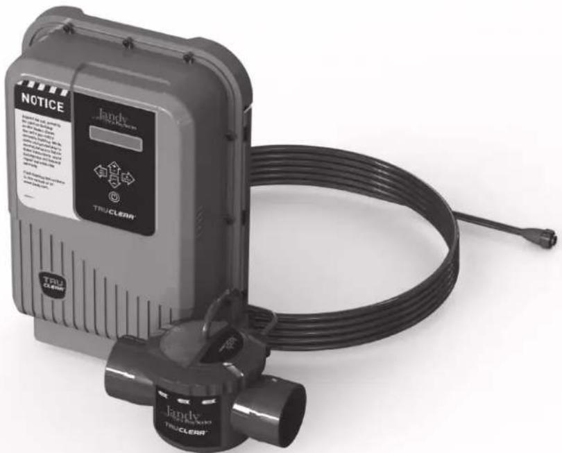
natural_image
Exterior view of a Jandy TRUCLEAR brand water heater with coiled cable and warning label (no readable text beyond branding)Zodiac Pool Systems LLC
2882 Whiptail Loop # 100 Carlsbad, CA 92010
Zodiac Pool Systems Canada, Inc.
2-3365 Mainway, Burlington, ON L7M 1A6 Canada
natural_image
Line drawing of a Jandy industrial control box with ventilation grilles and control panel (no text or symbols)
natural_image
Technical line drawing of a mechanical valve or pump component with no visible text or symbols
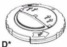
natural_image
Exterior view of a wall-mounted industrial control unit connected to a pipe with a valve (no visible text or symbols)natural_image
3D mechanical assembly diagram showing two components with alignment lines (no text or symbols)natural_image
Close-up of a TRU CLEAN appliance with a magnified inset showing internal components (no text or symbols visible)Installation standard
natural_image
Diagram of a mechanical assembly with pipes and a camera, showing a 6-inch length dimension (no text or symbols present)natural_image
Mechanical assembly diagram showing a valve with internal components and an upward arrow indicating motion (no text or symbols)natural_image
Diagram of a mechanical valve assembly with pipe connections and a magnified inset showing internal components (no text or labels)natural_image
Mechanical assembly diagram showing a valve or pump component with a central hub and internal components (no text or symbols)natural_image
Close-up of a mechanical component with threaded connectors and directional arrows indicating motion (no text or symbols)natural_image
Technical diagram showing mechanical assembly with labeled components and directional arrows (no readable text or symbols)natural_image
Technical diagram showing a robotic arm mounted on a vertical support with close-up insets illustrating internal components (no text or symbols present)
natural_image
Mechanical assembly diagram showing a valve with internal components and an upward arrow indicating motion (no text or symbols)natural_image
Interior view of a white cylindrical container with a coiled cable and a submerged mechanical component (no text or symbols visible)Zodiac Pool Systems LLC
2882 Whiptail Loop # 100 Carlsbad, CA 92010
Zodiac Pool Systems Canada, Inc.
2-3365 Mainway, Burlington, ON L7M 1A6 Canada
USA | Jandy.com | 1.800.822.7933
Canada | Jandy.ca | 1.888.647.4004

Certified to NSF/ANSI Standard 50
Zodiac Pool Systems LLC
2882 Whiptail Loop # 100 Carlsbad, CA 92010
Zodiac Pool Systems Canada, Inc.
2-3365 Mainway, Burlington, ON L7M 1A6 Canada

natural_image
Exterior view of a Jandy TruCLEAR device with coiled cable and connector (no visible text or symbols on main body)natural_image
Line drawing of a Jandy industrial control box with ventilation slots and a digital display (no text or symbols)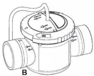
natural_image
Technical line drawing of a mechanical valve or pump component with no visible text or symbols

natural_image
Exterior view of a wall-mounted industrial control unit connected to a pipe fitting (no visible text or symbols)natural_image
3D mechanical assembly diagram showing two components with alignment lines (no text or symbols)natural_image
Close-up of a white industrial device with a label 'TRU CLEAR' and an inset close-up showing internal components (no readable text beyond labels)natural_image
Diagram of a mechanical assembly with pipes and a device, showing a 6-inch length dimension (no text or symbols present)natural_image
Mechanical assembly diagram showing a valve with internal components and an upward arrow indicating motion (no text or symbols)natural_image
Diagram of a pipe valve assembly with pipe fittings and a magnified inset showing a connector (no text or symbols)natural_image
Mechanical component diagram showing a valve assembly with a central shaft and housing (no text or symbols)natural_image
Close-up of a mechanical component with threaded connectors and directional arrows indicating motion (no text or symbols)natural_image
Technical diagram showing mechanical assembly with labeled components and directional arrows (no readable text or symbols)natural_image
Technical diagram showing mechanical assembly with labeled components and a close-up inset of a switch (no text or symbols present)natural_image
Map of the United States showing state boundaries with no text or labels
natural_image
Mechanical component diagram showing a valve assembly with a central hub and internal components (no text or symbols)natural_image
Interior view of a white cylindrical container with a black cable and a small mechanical component inside, placed on a plain surface (no text or symbols visible)Zodiac Pool Systems LLC
2882 Whiptail Loop # 100, Carlsbad, CA 92010
Zodiac Pool Systems Canada, Inc.
2-3365 Mainway, Burlington, ON L7M 1A6 Canada
USA | Jandy.com | 1.800.822.7933
Canada | Jandy.ca | 1.888.647.4004

Certified To NSF/ANSI Standard 50
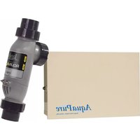
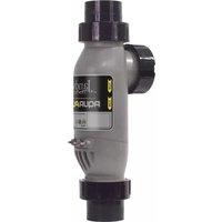

- WARNING
- Jandy TruClear™
- Chlorine Generating System
- Intertek
- Notice to User
- Table of Contents
- Section 1. Important Safety Instructions .....4
- Section 2. General Description ....8
- Section 3. Installation Instructions....10
- Section 4. Pool Water Preparation....17
- Section 5. Operating Instructions....21
- Section 6. Maintenance....24
- Section 7. Troubleshooting ...... 26
- Section 8. Display Readings......29
- Section 1. Important Safety Instructions
- READ AND FOLLOW ALL INSTRUCTIONS
- Safety Instructions
- To Reduce the Risk of Injury -
- CAUTION
- Product Contents
- Section 3. Installation Instructions
- Materials and Tools
- Tools and Materials Needed for Installation
- Installation Requirements
- Installing the Power Pack
- Installing the Cell
- Standard Installation
- Retrofitted Installation
- Wiring the Power Pack to the Power Source
- Install RS485 for Jandy Automation
- When Using In Non-automation Installations And With Jandy Variable Speed Pump
- Bonding
- Split Return Plumbing Instructions: For Infloor Cleaning Systems
- Section 4. Pool Water Preparation
- ATTENTION INSTALLER, PLEASE CHECK WATER CHEMISTRY PRIOR TO OPERATION
- Determining Pool Size (Litres)
- Determining Pool Size (Gallons)
- Chemistry You Need to Know
- Optimum Pool Water Conditions
- Collecting a Water Sample
- Salt (NaCl Sodium Chloride)
- When to add salt
- What Type of Salt to Use
- How Much Salt to Use
- How to Add Salt to the Pool
- Section 5. Operating Instructions
- Turning Power Pack On/Off (Manually)
- Select Language
- Turning Power Pack On/Off (Using the Pump's External Timer)
- • DISPLAY
- Chlorine Output Level
- BOOST/LOW Mode
- Polarity Reversal
- If your Total Hardness (TH)\* level is above
- Section 6. Maintenance
- Weekly
- Monthly
- Cleaning the Cell
- Winterizing
- Section 7. Troubleshooting
- Problems and Corrective Action
- Section 8. Display Readings
- NOTES
- Installation standard
Brand : Jandy
Model : TruClear
Category : Water pump