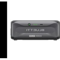
EP600 - Power bank BLUETTI - Free user manual and instructions
Find the device manual for free EP600 BLUETTI in PDF.
| Product Type | Solar energy storage system (EP600 inverter + B500 battery) |
| Brand | BLUETTI |
| Model | EP600 (inverter) + B500 (battery) |
| Rated power (inverter) | 6000 W / 6000 VA |
| Output voltage (grid) | 230/400 V three-phase, 50 Hz |
| Max PV input | 6000 W (2x MPPT, 3000 W each, max voltage 550 V) |
| Battery type | LiFePO4 |
| Nominal battery capacity (per B500 module) | 4.96 kWh (usable 4.464 kWh at 90% DoD) |
| Battery voltage | 99.2 V |
| Battery expansion | Up to 16 B500 modules in parallel (max 80 kWh) |
| Dimensions (EP600 inverter) | 636 x 325 x 370 mm |
| Weight (EP600 inverter) | 40 kg |
| Dimensions (B500 battery) | 626 x 338 x 324 mm |
| Weight (B500 battery) | 58 kg |
| Protection rating | IP65 (inverter and battery) |
| Operating temperature range | Inverter: -20°C to 50°C; Battery charge: 0°C to 40°C, discharge: -20°C to 40°C |
| Noise | Inverter ≤50 dB(A); Battery <25 dB (fanless) |
| Connectivity | Wi-Fi (2.4 GHz), Bluetooth, USB |
| App | BLUETTI (remote monitoring and control) |
| Main functions | Photovoltaic power supply, energy storage, uninterruptible power supply (UPS), smart management via app, battery expansion |
| Safety | Overvoltage, undervoltage, overcurrent, overtemperature, short circuit, residual current, anti-islanding, etc. |
| Maintenance | Regular cleaning with a soft dry cloth; check connections once a year; intervention by qualified professional |
| Warranty | 10 years (B500 battery) |
| Repairability | Only qualified personnel can intervene; contact BLUETTI support for any troubleshooting |
Frequently Asked Questions - EP600 BLUETTI
User questions about EP600 BLUETTI
0 question about this device. Answer the ones you know or ask your own.
Ask a new question about this device
Download the instructions for your Power bank in PDF format for free! Find your manual EP600 - BLUETTI and take your electronic device back in hand. On this page are published all the documents necessary for the use of your device. EP600 by BLUETTI.
USER MANUAL EP600 BLUETTI
Battery can be charged by grid, the charging time and power can be set flexible in APP.
text_image
QR code with a blue triangular logo in the center, likely linking to a digital resource or website.
Avertissement
For more information, please visit:

@ BLUETTI Support
@ BLUETTI Official

@ bluetti_inc

@bluetti.inc

@bluetti_official

sale-eu@bluettipower.com sale-uk@bluettipower.com
EU REP
Address: Unit 2 Northgate, Bolsover Business Park,
Woodhouse Lane Chesterfield England, S44 6BD
Mail:poweroak.eu@bluetti.com
After-sales address in EU : Lise-Meitner-Strasse 14, 28816 Stuhr, Germany
After-sales address in UK: Unit 2 Northgate, Bolsover Busines Park, Woodhouse Line,
Chesterfield England S44 6BD
User Manual
EP600 ENERGY STORAGE SYSTEM
Shenzhen PowerOak Newener Co., Ltd
text_image
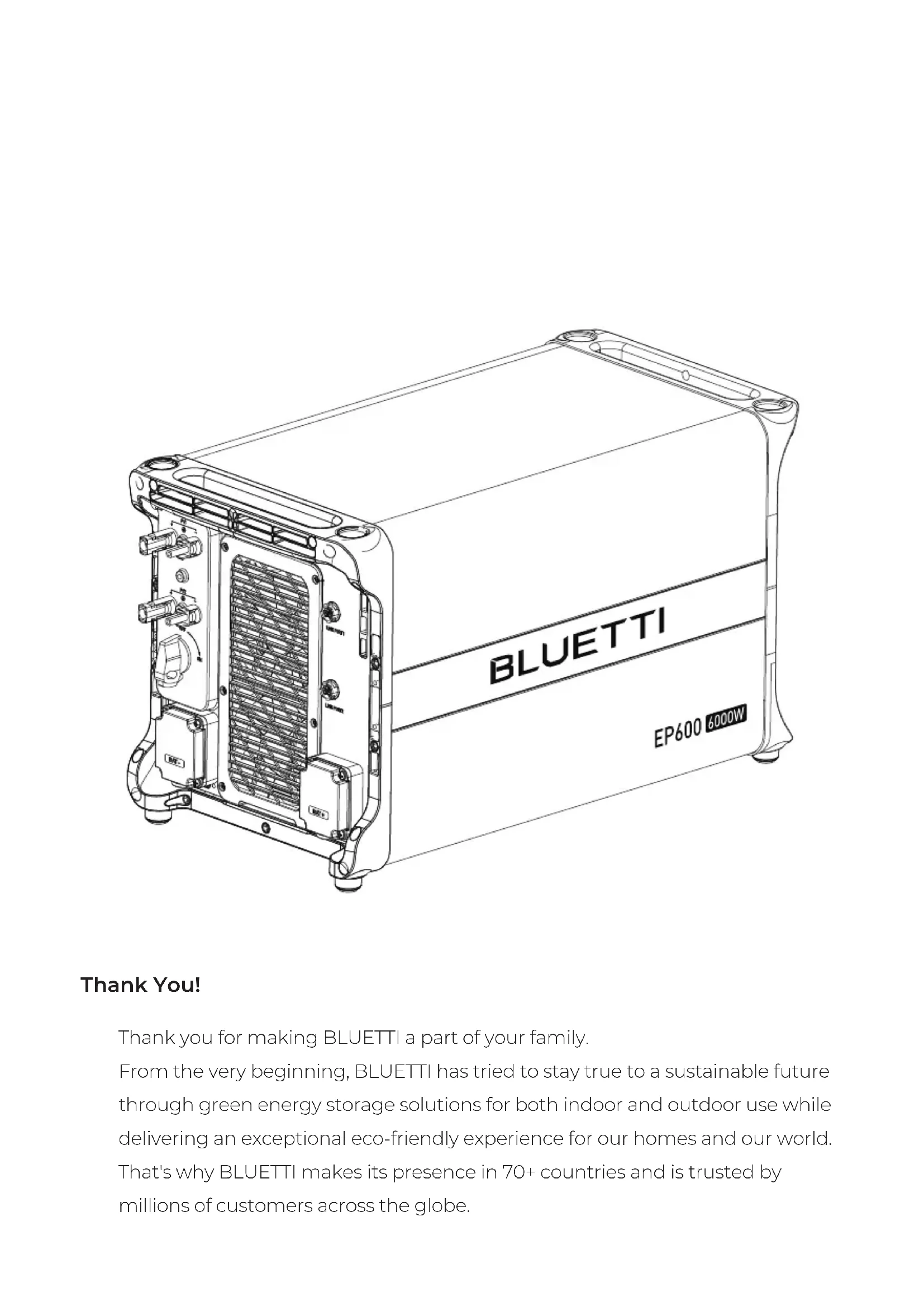
BLUETTI EP600 6000WThank You!
Thank you for making BLUETTI a part of your family.
From the very beginning, BLUETTI has tried to stay true to a sustainable future through green energy storage solutions for both indoor and outdoor use while delivering an exceptional eco-friendly experience for our homes and our world.
That's why BLUETTI makes its presence in 70+ countries and is trusted by millions of customers across the globe.
Instruction
Copyright statement
The copyright of this manual belongs to Shenzhen PowerOak Newener Co., Ltd, without the written permission of the company, any company or individual is not allowed to extract or copy part or all of the contents of this manual, and shall not disseminate it in any way.
Attention
The products, services or features you purchase shall be subject to the commercial contracts and terms of our company. All or part of the products, services and features described in this manual may not be within the scope of your purchase. Unless otherwise agreed in the contract, this manual is only used as a guide, and the company makes no express or implied representations or warranties about the contents of this document. Shenzhen PowerOak Newener Co.,ltd (hereinafter referred to as our company) reserves the right of final interpretation.Due to product version upgrade or other reasons, the contents of this manual will be updated from time to time. You can log in to our website: http:www.poweroak.net to check the latest version.
Summary
This user's manual introduces the installation, electrical connection, debugging, maintenance and troubleshooting of EP600 energy storage system, and the tutorial of user operation interface. When installing and using the system, please read the manual carefully, understand it's safety knowledge, and be familiar with it's functions and characteristics.
Reader
This guidebook is applicable to:
Professional technicians who need to install, operate and maintain the EP600 energy storage system.
User who learn to use BLUETTI APP for interface operation.
Conventional symbols
In order to ensure the personal and property safety of users when using the Energy Storage System and use the Energy Storage System more efficiently and optimally, the manual provides relevant information and highlights it with the following symbols. The symbols that may be used in this manual are listed below. Please read them carefully to better use this manual.
 | Danger |
| It indicates that there is a high potential danger, it may cause death or serious injury if not avoided. | |
 | Warning |
| It indicates that there is a moderate potential danger, it may cause death or serious injury if not avoided. | |
 | Caution |
| It indicates that there is a mild potential danger, it may cause moderate or mild injury if not avoided. | |
 | Attention |
| It indicates that there is potential risk. It may cause abnormal operation of the Energy Storage System or property loss if not avoided. | |
 | Instruction |
| The "Instructions" are not safety warning and do not involve information about personal, Energy Storage System and environmental injuries. |
Content
1 SAFETY INSTRUCTION 48
2 EP600 energy storage system 60
3 EP600 Inverter instruction 63
4 B500 Battery Pack Introduction 67
5 System Check 70
6 BLUETTI App 72
7 Dispose of the Inverter 74
8 Troubleshooting 74
9 Specifications 79
9.1 EP600 79
9.2 B500 82
10 Appendix 84
1.SAFETY INSTRUCTIONS
 | Warning |
| Please don't insert foreign object into any port of Energy Storage System. Please be aware of operating and keep children away from the Energy Storage System. If the Energy Storage System is on fire, please use dry powder extinguisher to put out the fire.For security, please use the cables configured by the original factory.We will not responsible for the equipment damage cause by the third-party device. | |
 | Instruction |
| The safety requirement of the guidebook aren't including the whole technical requirement but a supplementary instruction, the actual operation are contact with the on-site condition. |
1.1 Safety Instructions
1.1.1 Safety Instructions
Please read this manual before using the equipment.
The installation, testing, and maintenance should be performed by qualified professionals or trained personnel only. Improper use, incorrect installation or incorrect operation may cause serious personal or property losses.
Do not keep the equipment near heat sources or in high temperatures.
Do not store the equipment with flammable liquids, gases, or explosive materials.
Make sure the place where you are using the equipment is well ventilated and spacious.
Do not block or cover the openings of the equipment, as this may cause irreversible damage to it.
Do not stack anything on top of the equipment either in storage or in use.
Do not move the equipment while it is turned on, as vibration and collision may cause damage to the internal hardware.
Turn off the equipment IMMEDIATELY in case of malfunction, and contact BLUETTI support team if this manual cannot explain the malfunction adequately to you.
Do not place the equipment on unstable or inclined surfaces.
Keep away from children and pets.
1.1.2 Battery Safety
Use the battery within the temperature range specified in this manual.
Do not expose the battery to high temperatures or around heat sources, such as sunlight, fire, transformers and heaters. If the battery overheats, it may cause a fire.
Do not expose the battery to humidity or corrosives, as this may cause the battery to rust, corrode and leak chemicals.
To avoid leakage, overheating or fire, do not disassemble, modify or damage the battery. For example, do not insert foreign objects into the battery or place the battery in water or other liquids.
Move the battery in the correct direction. Do not turn the battery upside down or tilt it.
Do not ignore warning signs on parts or products made by the manufacturer.
Do not short-circuit the battery terminals. A short circuit can cause a fire.
Do not use the battery beyond the warranty period.
Never use damaged batteries or components. Improper use or misuse of damaged batteries or components can damage your device or injure yourself as a result of battery fluid leakage, fire, overheating, or explosion.
Do not place damaged batteries near flammable materials.
Do not store damaged batteries near undamaged ones, as damaged batteries may leak flammable liquid or gas. Only qualified professional or trained personnel is allowed to approach damaged batteries.
Do not perform welding or grinding work around the battery to prevent fire caused by sparks or arcs.
The fire hazard of lithium-ion battery energy storage system is high. Before handling batteries, consider the following risks:
i) Battery thermal runaway may produce flammable and harmful gases such as CO and HF. Vapors from burning batteries may irritate eyes, skin and throat.
ii) The concentration of flammable gases from battery thermal runaway may lead
to deflagration and explosion.
iii) The battery electrolyte is flammable, toxic and volatile.
Avoid contact with spilled liquid or gas if the battery leaks chemicals or odors. Do not approach the battery and contact a professional for disposal. Professionals must wear goggles, rubber gloves, gas masks and protective clothing.
If any part of the battery is immersed in water, do not touch the battery to avoid electric shock.
Electrolyte is corrosive and can cause irritation and chemical burns. If you come into direct contact with battery electrolyte, do the following:
Inhalation of Vapors: Evacuate contaminated area, get fresh air immediately, and seek medical attention.
Eye Contact: Immediately flush eyes with water for at least 15 minutes, do not rub eyes, and seek medical attention immediately.
Skin Contact: Immediately wash the infected area with soap and water and seek medical attention immediately.
Ingestion: Seek medical attention immediately.
1.1.3 Personal Safety
To ensure personal safety and normal use of the equipment, the equipment must be reliably grounded before use.
Wear personal protective equipment (PPE) during operation. If there is a possibility of personal injury or equipment damage, stop operation immediately, and take appropriate protective measures.
Use tools correctly to avoid injury or damage to equipment.
Do not touch energized equipment.
Do not clean the electrical components inside and outside the cabinet with water.
Do not stand, lean on or sit on top of the equipment.
Do not damage the equipment modules.
When the battery fails, avoid touching the battery and be careful of high temperature.
Do not disassemble or damage the battery. The released electrolyte is harmful to
your skin and eyes. Avoid contact with electrolyte.
Batteries can cause electric shock and high short-circuit current. When using batteries, please note the following:
(a) Remove any metal objects, such as watches and rings, from yourself.
(b) Use tools with insulated handles.
(c) Wear rubber gloves and boots.
(d) Avoid the metal objects to short circuit battery terminals.
(e) Do not place tools or metal parts on top of the battery.
(f) Disconnect the charging power source before connecting or disconnecting battery terminals.
1.1.4 Battery Installation Requirements
Before installing the battery, please check whether the packaging is in good condition. Do not use batteries with damaged packaging, make sure the battery switch is OFF.
During installation, make sure the screws are properly tightened with a torque wrench and check regularly.
During installation, make sure that the positive and negative terminals of the battery are not short-circuited. If the battery terminals contact with other metals, it may cause the heat generation or electrolyte leakage.
After installing the equipment, remove unused packing materials such as foam, carton, plastic and excess cables from the equipment area.
Fire Emergency Measures

Danger
• In case of fire, power off the system if it is safe to do so.
• Use carbon dioxide, FM-200 or ABC dry powder fire extinguisher.
- Remind firefighters to avoid contact with high-voltage components to prevent the risk of electric shock.
• Overheating may cause the battery to deform and leak corrosive electrolyte or toxic gas. Keep away from batteries to avoid skin irritation and chemical burns.
Battery Drop Emergency Measures

Danger
- If the battery pack is dropped, violently impacted or tilted during installation, internal damage may occur. So do not use such battery packs to avoid safety risks such as battery leakage and electric shock.
- If the dropped battery is not obviously deformed or damaged, and there is no abnormal smell, smoke or fire, please contact a professional to transfer the battery to an open and safe place, and
- contact BLUETTI.
If the battery is obviously damaged or there is abnormal smell, smoke or fire, please evacuate immediately, contact a professional or contact BLUETTI. Professionals can use fire extinguishing facilities to extinguish the fire under safety protection.
text_image
BLUETTI B500 4260Wh BLUETTI B500 4260Wh1.1.5 Battery Recycling
If the battery is out of service life, please contact a battery recycling company for disposal.
Dispose of used batteries according to local laws and regulations, and do not dispose of batteries as household waste.
If the battery leaks or is damaged, please contact technical support or a battery recycling company for disposal.
1.1.6 Declaration
BLUETTI shall not be liable for equipment abnormality component damage, personal injury property loss or other damage caused by the following reasons:
After being installed and connected to the system, the battery is not charged in time, resulting in and gets damaged due to over-discharge.
Batteries are often over-discharged due to improper maintenance or capacity expansion (eg, mix new and used batteries), or batteries have not been fully charged for a long time.
Failure to maintain the battery in accordance with the user manual.
The battery is not charged as required during storage, resulting in the capacity loss or irreparable damage to the battery.
Batteries are short- circuited, damaged, dropped or leaked due to improper operation or connection errors.
The battery is used by the customer or a third party beyond the situations specified in the user manual. For example, use with other batteries, including but not limited to other brands of batteries or batteries of different rated capacities.
The battery is damaged because the working environment does not meet the requirements. The actual operating temperature is too high or too low, or it is exposed to rain.
1.2 Precaution of installation

Attention
Please attention, it's forbidden to power on EP600 energy storage system in the process of installation.
Please measure the voltage of contact point to make sure there's no risk of electric shock before touching any conduct's surface or metal terminal;
After the Energy Storage System is installed, please clean out the package material promptly, such as cartons, foam, plastics, nylon ties, etc;
Except the operator, please keep other people away from the Energy Storage System;
Please use original package or other material to packing the Energy Storage System for shockproof protection when moving;
All ports of the Energy Storage System must be sealed, and according the requirement to install the machine;
Forbid to alter ,damage or cover the identification and nameplate of Energy Storage System;
Please use the suitable tool to lock the screws tightly when installing the Energy Storage System;
Please fix the Energy Storage System on the group or other stable object(such as the wall or the frame) before operating;
Forbid to use water to clean the Energy Storage System or any electronic components;
Forbid to arbitrarily change or modify the structure, the order of install, etc.
1.2.1 Requirement of installation and maintenance personnel
EP600 energy storage system installation, electrical connection, test, maintenance, troubleshooting and replace operation must be operated by professional electrical technician. EP600.
The installation and maintenance personnel must have received professional
training, have clear knowledge about the Energy Storage System safety instruction and master the correct operation.
Professional personnel: Personnel who have received correspond technical training can clearly realize what risk may be brought to them during the operation, and able to take measure promptly to minimize the personal risk.
Energy Storage System or components (include software) must be replaced by professionals or authorized personnel.
1.2.2 Requirement of anti-static
When installing the cables, it is recommended to wear anti-static glove or anti-static bracelet before contacting the Energy Storage System. The other side of anti-static Bracelet should be grounded properly. Don't touch any exposed components directly with your hand.
1.2.3 Precaution of drilling
When drill on the wall or ground, the following safety protection measures should be considered;
Forbid to drill on the Energy Storage System. Drilling will damage the Energy Storage System's appearance, internal components and cable insulation. In addition, if metal debris enters the internal of Energy Storage System, it will cause internal circuit board short circuit;
Wear goggles and protective gloves when drilling;
In the process of drilling, the power station should be covered and protected in case of the debris or dust drop into the power station. The debris and dust should be cleaned out promptly after drilling.
1.3 Precaution of electrical connection
The EP600 energy storage system will generate high voltage during operating, which may cause casualties, personal injury or serious damage to property. Please comply with relevant safety regulations during the installation、trial run、operation and maintenance of the product.
 | Danger |
| Before connecting the power supply, make sure the Energy Storage System is not damaged, otherwise it may cause danger. Make sure the Energy Storage System and all relevant switches are in the "OFF" state, otherwise it may cause the electric shock. | |
 | Warning |
| All installation must only be operated by professionals or authorized personnel.The specification of cables which used for solar panel must proper, firm connection and good insulation. Incorrect wiring may damage the Energy Storage System, such resulting damage will not within the warranty. | |
 | Attention |
| The EP600 energy storage system can be grid-connected for power generation only with the permission of the electricity power department of the country or region. |
Precaution of operation
 | Danger |
| When the Energy Storage System is running, please do not touch any terminal of the Energy Storage System, otherwise it may cause the electric shock. When the Energy Storage System is running, the shell temperature is high, please do not touch it, otherwise it may cause the burn injury. | |
 | Attention |
| In the process of moving the Energy Storage System, the weight of Energy Storage System shall be considered and take care of the balance to avoid the Energy Storage System overturn or fall. |
Precaution of repair and maintenance
 | Danger |
| In the process of operating the Energy Storage System, there exist high voltage which may cause electric shock, result in the casualty or serious damage of personal injury and property. Therefore, the Energy Storage System must be shut down and powered off before operate any maintenance, and the precaution of safety which listed in this guidebook and other relevant documents must be strictly followed when operating the Energy Storage System. | |
 | Danger |
| Before operating any maintenance, the electrical connection between the Energy Storage System and the grid must be disconnected first, then disconnect the electrical connection between inverter and PV, battery pack. Wait for at least 30 minutes until the internal components are discharge completely then the maintenance can be operated. | |
 | Attention |
| In the process of maintenance, please observe the precaution of anti-static, wear anti-static gloves.If any maintenance is required, please contact the local authorized maintenance center. During the maintenance, please try to avoid irrelevant personnel from entering the maintenance site, temporary warning signs or fences must be erected for isolation. |
The label of Energy Storage System
There are some symbol related safety on the Energy Storage System's label. Please carefully read and fully understand the content of these labels before installing the Energy Storage System.
Figure 1-1 Safety label
| Symbol Symbol | name Symbol mean | |
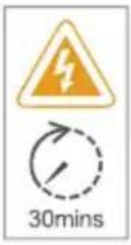 | Delay discharge label | There still exist residual voltage after power off the Energy Storage System, it needs to wait for 30 minutes to ensure that the discharge is completed, then the maintenance can be operated. |
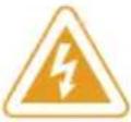 | Anti electric shock warning symbol | This Energy Storage System has high voltage during operation. All operations of the Energy Storage System must be operated by trained professional electrical technician. |
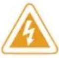 | Warning symbol | There are potential danger after the Energy Storage System is operated. Please take precautions during operation. |
 | Read instruction | Please read the instruction carefully before operate the Energy Storage System |
 | European standard CE certification | This product comply with European standard CE certification. |
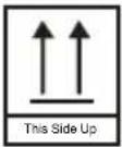 | This side up | It must always be transported, handled and stored in this way that the arrow always point upward. |
 | Weight symbol | The inverter and battery pack are pretty heavy and need to be moved by multi-people. |
1.4 Precaution of transportation
When this product leaves the factory, it is in the best electrical and mechanical state. It's necessary to use the original package or appropriate package of the product to ensure the safety of the Energy Storage System during transportation.
The transportation company will be responsible for the machine damage caused during transportation. Please conduct a thorough check when picking up the products. If any packaging problems that may cause damage to the product or any visible damage of the product have been found, please notify the responsible transportation company immediately. If necessary, you can ask your installer or our company for help.
1.5 Box identification protection
The identification on the box contains important information for safe operation. It is forbidden to alter or damage it.
There's a nameplate on the side of the box, which contains important parameter information relate to the product. It is forbidden to alter or damage it.
The label shouldn't be covered, please clean up regularly. It should be always visible.
1.6 Storage instruction
If the EP600 energy storage system isn't put into use immediately, the storage shall meet the following requirements:
Please power off the Energy Storage System and charge it to 50-70% of capacity before storage;
In order to keep the battery healthy, please fully charge and discharge it every six months;
When using or storing, please make sure the ventilate are proper.
Please keep away from flammable and explosive object or gas. It is recommended to place them in a clean and dry environment.
It's strongly recommended to frequently clean the dust and debris outside the Energy Storage System with dry soft cloth.
Keep away from children and pet.
Please do not place anything on the top of the Energy Storage System when using or storing.
Avoid exposing to the equipment with rain, humidity or direct sunlight.
The details of storage temperature please view "11.basic parameter".
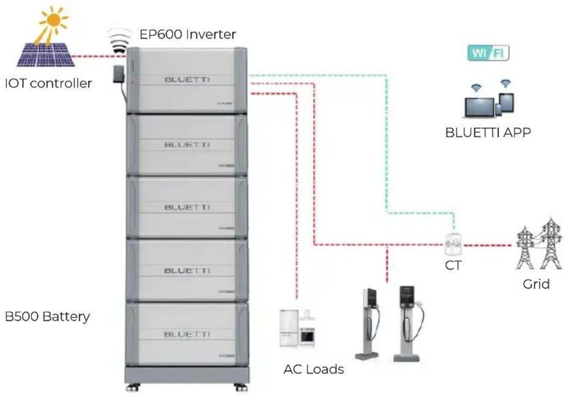
2.EP600 energy storage system
2.1 EP600 energy storage system instruction
The EP600 energy storage system include grid-connected inverter (EP600)、energy storage battery pack (B500), IOT controller and other accessories (CT, cables, etc.), which can form a household energy storage and PV grid-connected power generation system with photovoltaic (PV) and user distribution box,etc; This system is suitable for families and regions with energy shortage or unstable power supply. The system has intelligent power generation and UPS function, and it can be operated and monitored by APP. It is simple operation, economical and practical.
The block diagram of EP600 energy storage system shown as below:
flowchart
graph TD
    A["B500 Battery"] -->|AC Loads| B["EP600 Inverter"]
    B --> C["Grid"]
    B --> D["CT"]
    D --> E["BLUETTI APP"]
    E --> F["Wi-Fi"]
    G["IOT controller"] --> H["Wireless Sensor"]
    H --> I["Smart Meter"]
    I --> J["AC Load"]
    J --> K["Grid"]
    style A fill:#f9f,stroke:#333
    style B fill:#ccf,stroke:#333
    style C fill:#cfc,stroke:#333
    style D fill:#fcc,stroke:#333
    style E fill:#cff,stroke:#333
    style F fill:#ffc,stroke:#333
    style G fill:#f9f,stroke:#333
    style H fill:#ccf,stroke:#333
    style I fill:#cfc,stroke:#333
    style J fill:#fcc,stroke:#333
    style K fill:#ffc,stroke:#333
Figure 2-1 EP600 Energy storage system

Instruction
The introduction describes the general behavior of EP600 energy storage system, and the system operating mode can be adjusted on the APP of this product.
2.2 Working mode
The following are the general working modes of the EP600 energy storage system. According to your configuration and layout condition to select the working mode.
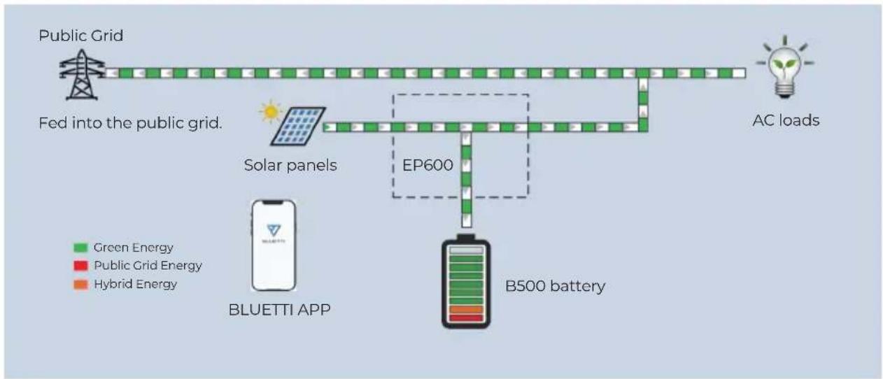
Mode 1
PV generate power to the load, the overflow power will charge the battery first, then output to the grid;
flowchart
graph TD
    A["Public Grid"] --> B["Fed into the public grid."]
    B --> C["Solar panels"]
    C --> D["EP600"]
    D --> E["B500 battery"]
    E --> F["AC loads"]
    G["BLUETTI APP"] --> H["Green Energy"]
    G --> I["Public Grid Energy"]
    G --> J["Hybrid Energy"]
Figure 2-1
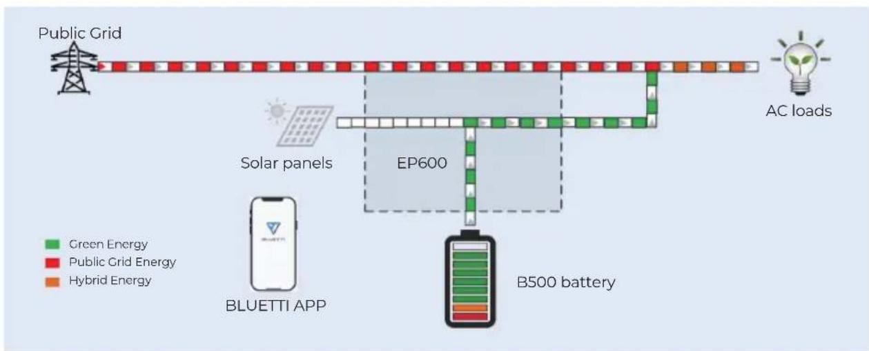
Mode 2
When there's no PV output, battery will provide power to the load first, then grid provide power when battery is in low power.
flowchart
graph TD
    A["Public Grid"] --> B["EP600"]
    B --> C["B500 battery"]
    D["AC loads"] --> E["Blueuetti APP"]
    F["Solar panels"] --> B
    G["Green Energy"] --> B
    H["Public Grid Energy"] --> B
    I["Hybrid Energy"] --> B
    style B fill:#f9f,stroke:#333
    style C fill:#ccf,stroke:#333
    style D fill:#cfc,stroke:#333
    style E fill:#fcc,stroke:#333
    style F fill:#cff,stroke:#333
    style G fill:#ffc,stroke:#333
    style H fill:#fcc,stroke:#333
    style I fill:#ffc,stroke:#333
Figure 2-2
Mode 3
When the power grid is cut off, PV and battery will provide power to the load together.
flowchart
graph TD
    A["Public Grid"] --> B["AC loads"]
    B --> C["B500 battery"]
    C --> D["BLUETTI APP"]
    D --> E["Solar panels EP600"]
    E --> F["Green Energy"]
    E --> G["Public Grid Energy"]
    E --> H["Hybrid Energy"]
Figure 2-3
Mode 4
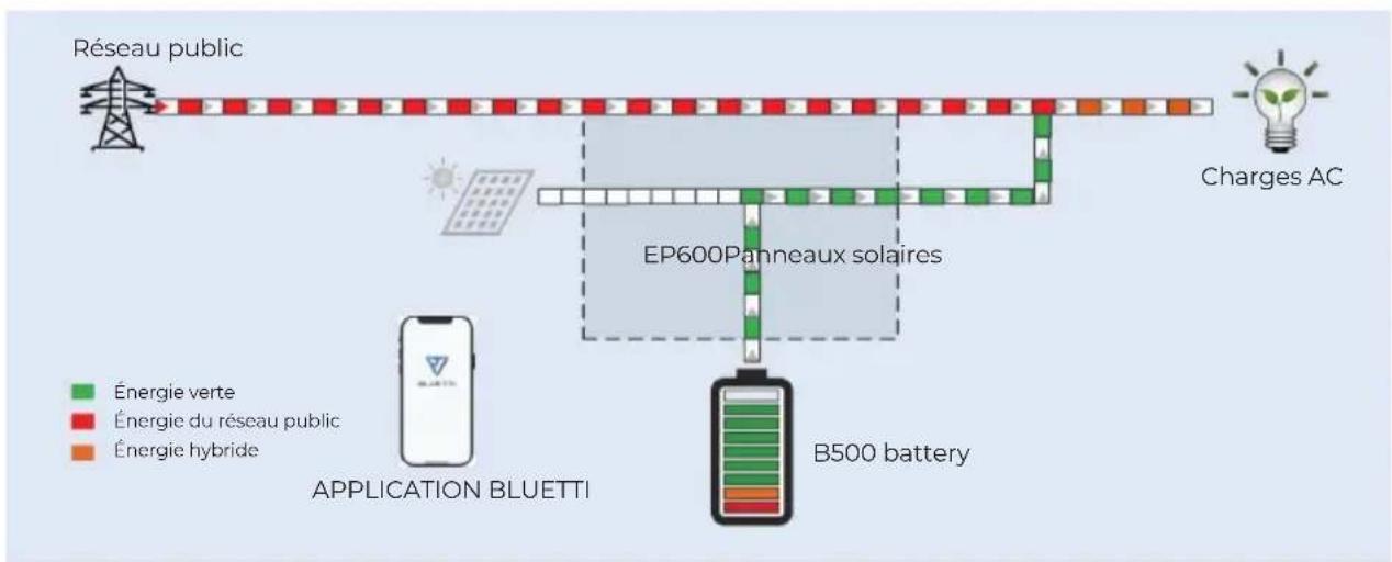
Battery can be charged by grid, the charging time and power can be set flexible in APP.
flowchart
graph TD
    A["Public Grid"] --> B["EP600 Solar panels"]
    B --> C["B500 battery"]
    D["AC loads"] --> E["EC blocks"]
    F["BLUETTI APP"] --> G["Smartphone"]
    style A fill:#f9f,stroke:#333
    style B fill:#ccf,stroke:#333
    style C fill:#cfc,stroke:#333
    style D fill:#fcc,stroke:#333
    style E fill:#cff,stroke:#333
    style F fill:#ffc,stroke:#333
    style G fill:#fcc,stroke:#333
Figure 2-4
3.EP600 Inverter instruction
Ep600 inverter is a three-phase PV energy storage inverter integrate PV input and grid-connection charging and discharging. It is an important part of EP600 energy storage system.
3.1 The function and character of EP600 inverter
PV application: Dual MPPT, which can achieve PV charge and storage energy, and also can generate power with grid-connected system.
Energy storage application: Intelligent user application mode, which can automatically control the flow of system charging and discharging power or according the user demand to adjust the energy actively.
UPS application: Under the uninterruptible power supply (UPS) mode, the switching time of on-grid and off-grid is less than 10ms, and off-grid output can connect the unbalanced load.
Battery expansion: Support parallel with 2-16 battery packs (B500) to expand the total capacity.
Intelligent monitor: WiFi / Bluetooth, support using app to control and monitor, and check the system condition at anytime and anywhere.
High protection: The protection level of the system is IP65, which can be installed and used in great majority environments.
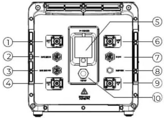
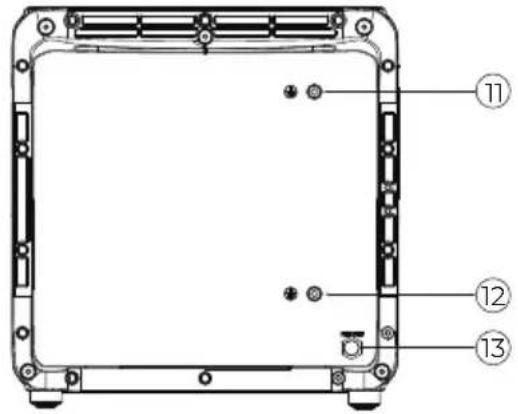
3.2 Appearance instruction
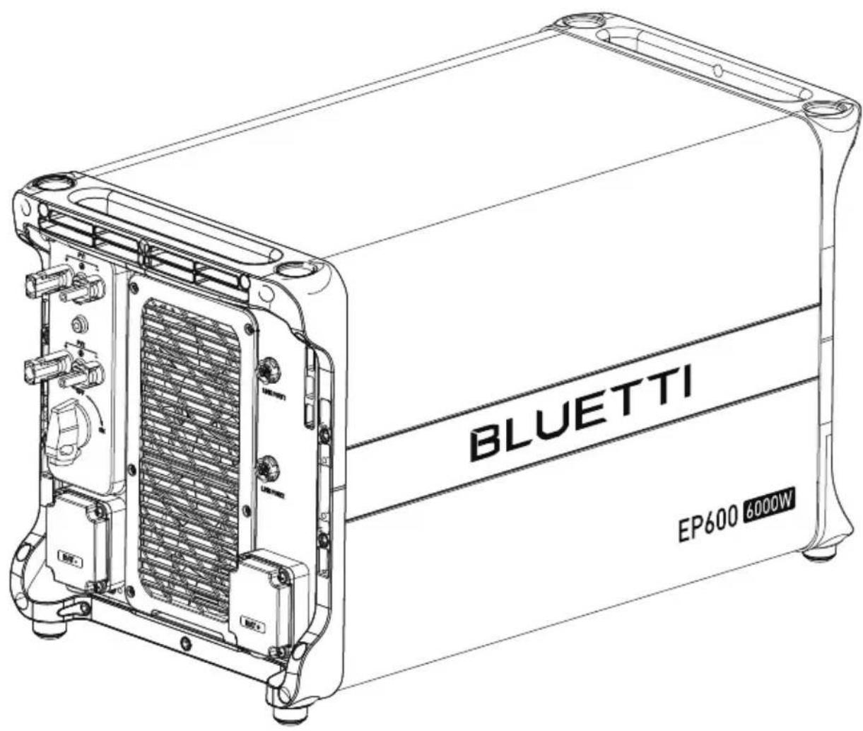
EP600 Inverter product appearance
Figure 3-1
text_image
BLUETTI EP600 Left Right BLUETTI EP600Figure 3-2
 | 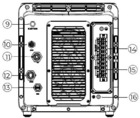 | ||
| Left | Right | ||
| No. | No.Port name | Port name | |
| 1 | PV input 1 | 9 | Waterproof and ventilate valve |
| 2 | PV input 2 | 10 | COM Communicate Port |
| 3 | DC ON/OFF | 11 | CT Input Port |
| 4 | Battery Negative | 12 | DRMs Port |
| 5 | LED Indicator | 13 | USB Port |
| 6 | Signal Port 1 | 14 | Load Port |
| 7 | Signal Port 2 | 15 | Grid Port |
| 8 | Battery Positive | 16 | Ground |
EP600 Inverter port description
Figure 3-3 (Unit: mm/in)
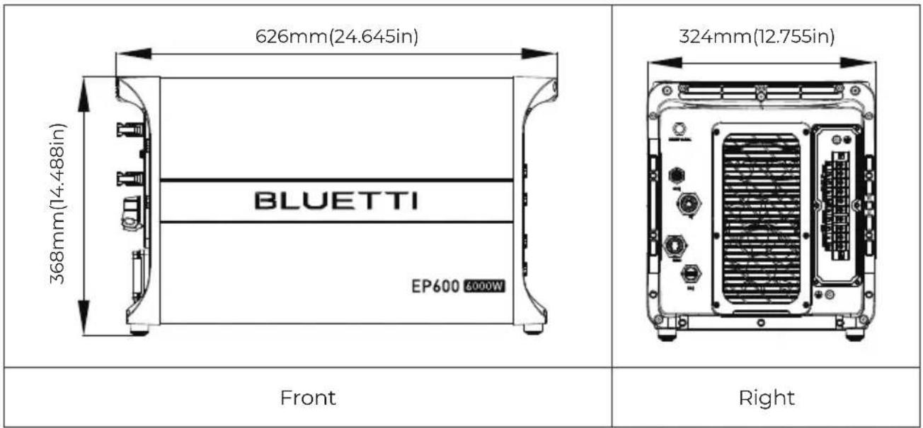
text_image
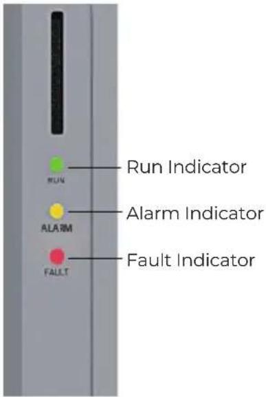
626mm(24.645in) 368mm(14.488in) BLUETTI EP600 6000W 324mm(12.755in) Front Right3.3 LED Indicator
text_image
Run Indicator Alarm Indicator Fault Indicator| States | Run Green light | Alarm Orange light | Fault Red light |
| No alarm and No fault | Always ON | / | / |
| Alarm without fault | Always ON Always ON | / | |
| No alarm with fault | / | / | Always ON |
| Alarm and fault | / Always ON Always ON | ||
Figure 3-2 Table 3-4
3.4 Buzzer Alarm
When the buzzer setting is enabled:
When a new fault occurs, the buzzer sounds for 5s and stops for 1s. It will stop sounding after 10 cycles.
| Fault Code | Content |
| 5. BUS overvoltage | |
| 7. | Battery overvoltage |
| 8. | Inverter overcurrent |
| 10. | LLC current overcurrent input |
3.5 Routine maintenance
EP600 inverter requires regular maintenance, details shown as follow:
Check whether dust and other blockages are attached to the air outlet and the heat sink. If the fan is blocked or there is too much dust on the heat sink, clean the fan, fan guard or heat sink.
Check whether the fan makes abnormal noise when running.
Check whether the cable connection is loose or disconnected. Please use a torque wrench to tighten the AC and DC cable connections annually.
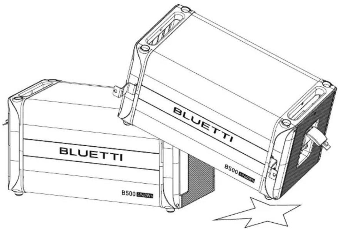
4.B500 Battery Pack Introduction
4.1 B500 Product Information
The B500 energy storage battery system is designed for residential and small commercial uses. Single pack rated capacity is 4.96KWh. It support 16 battery packs in parallel to meet capacity up to 80KWH.
The B500 battery management system adopts a multi-level architecture, which can detect the voltage, current and temperature of the battery pack in real time during the charging and discharging process. Accurately and efficiently realize the over-voltage, under-voltage, over-current, over-temperature and under-temperature protection of the system.
The safety function of B500 control system adopts redundant design, which meets the functional safety requirements and has good safety and stability.
4.2 Appearance Description
Appearance of B500 Battery Pack
Figure 4-1
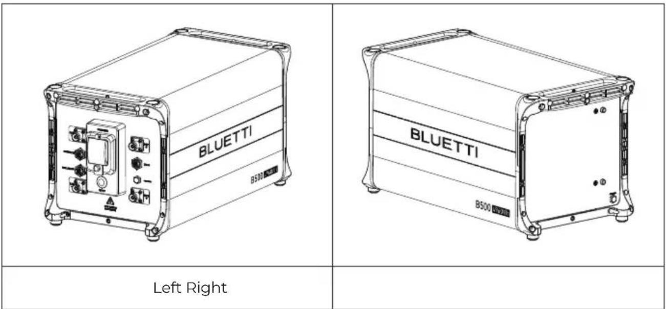
text_image
BLUETTI B500 BLUETTI B500 Left RightFigure 4-2
 |  | ||
| Left | Right | ||
| No. | No.Port name | Port name | |
| 1 | Negative output cable port (Upper) | 8 | Waterproof and breathable valve |
| 2 | Signal connection cable port (Upper) | 9 | Positive output cable port (bottom) |
| 3 | Signal cable port (Bottom) | 10 | ON/OFF Switch |
| 4 | Negative output cable port (Bottom) | 11 | Ground wire port(Upper) |
| 5 | Manual mechanical switch | 12 | Ground wire port (Bottom) |
| 6 | Positive output cable port (upper) | 13 | Waterproof and breathable valve |
| 7 | Inverter signal cable port | ||
B500 Battery Pack Port Description
Figure 4-3 (Unit: mm/in)

text_image
626mm(24.645in) 338mm(13.307in) BLUETTI B500 49&8Wh 324mm(12.755in) Front Right4.3 Indicator Descriptions
| Light Status | Meaning Remark | |
| OFF B500 not start | The circuit breaker can be operated now | |
| ON | B500 is operating | The circuit breaker can't be operated now |
| 0.5Hz Flash | B500 is shutting down | The circuit breaker can't be operated now |
| 1Hz Flash | B500 is not operating | If all B500 are flashing, it means that the B500 is temporarily unavailable and is restoring, please wait patiently. If it lasts for more than 1 hour, contact the authorized dealer or our company.If a single B500 flashes, it means the B500 is in fault status. Please contact the authorized dealer or our company immediately. |
4.4 Product Maintenance
If you find battery packs connected in parallel, and some of the battery pack indicators are off, please contact the authorized dealer or our company immediately.
If you find the B500 battery pack is in a faulty state, please contact the authorized dealer or our company immediately.
If you find the B500 battery pack is temporarily unable to work and is restoring, please wait patiently. If it lasts for more than 1 hour, contact the authorized dealer or our company immediately.
The circuit breaker automatically turns “OFF”, which means the system is failure. The user are forbidden to operate currently, must be handled by the after-sales service, must contact the dealer or the manufacturer.
Do not disconnect the circuit breaker when the B500 battery pack is in normalservice state. Otherwise it may cause the B500 battery pack abnormal work .
Do not remove the metal shell of the B500 battery pack under any circumstances. Otherwise, it may cause electric shock and explosion.
5.System Check
5.1 Preliminary Check
Check the followings before first use.
- Confirm that all components of the system are installed according to specific requirements.
- Make sure the PV+/PV- and BAT+ and BAT- cables are connected with correct polarity and proper voltage.
- Switch off all AC and DC circuit breakers.
- Circuit breakers should be selected according to the requirements of this manual and local regulations.
- Make sure grid and load cables are held firmly in place.
- All safety signs and warning labels shall be firmly attached and clearly visible when needed.
5.2 Power On
Step1: Switch on the DC circuit breakers on EP600.
Step2: Switch on the DC circuit breakers on B500 battery packs. Press and hold the power button of any battery pack for 3 seconds and the green indicator on the button lights up.
Step3: Wait for 40 seconds until the green indicator of the inverter is always on.
Step4: Switch on the AC circuit breakers connected to the EP600 grid port.
Step5: Power on the system via the BLUETTI app. For details, please refer to Setting section on App Manual.
Step6: Check the voltage of BACKUP.
Step7: Switch on the AC circuit breakers connected to the EP600 load port.
END, Then you can check the EP600 system status through the app.
5.3 Power Off
Step1: Turn off the AC power on BLUETTI App.
Step2: Switch off the AC circuit breakers which are connected to EP600 grid port and load port.
Step3: Switch off EP600 PV switch.
Step4: Press the power button on any B500 till the indicator on the button flashes green.
Step5: The indicator on the B500 continues to flash.
Step6: When the indicator is off, B500 battery packs turn off.
Step7: Switch off all B500 manual switches and the system powers off.

Wait at least 30 minutes after powering OFF the system before performing maintenance or inspections, as this may cause electric shock or burns.
6.BLUETTI App
6.1 Introduction
BLUETTI app allows you to monitor and control the EP600 inverter system in the palm of your hand via Bluetooth or WiFi, with features like In-time Alarm, Error Message, Data Collection, Operation Status, Parameter Configuration, and Firmware Upgrade.
6.2 Download
Scan the QR code to download the BLUETTI app. Or get the app from App Store or Google Play.
Please visit https://www.bluettipower.com for details

text_image
QR code with a blue triangular logo in the center, likely linking to a digital service or website.
Attention
Please update the firmware to the latest version in the APP before using.
6.3 Connection
EP600 inverter system connects to BLUETTI app via Bluetooth or WiFi.
Bluetooth Connection
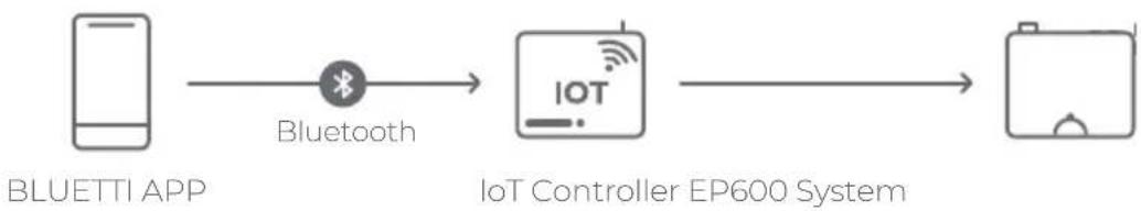
flowchart
graph LR
    A["BLUETTI APP"] -->|Bluetooth| B["IoT Controller EP600 System"]
    B --> C["Output"]
Fig. 5.1 Bluetooth Connection
WiFi Connection

flowchart
graph LR
    A["Smartphone"] -->|WiFi| B["Server with WiFi icon"]
    B <--> C["IoT Controller"]
    C <--> D["EP600 System"]
    D --> E["Output"]
Fig. 5.2 WiFi Connection
Note:
• Supported operating systems: Android 6.0 or above, iOS 11.0 or above.
- Bluetooth is available on your phone.
• The router supports WiFi of IEEE 802.11 b/g/n, 2.4GHz.
- BLUETTI recommends a router with WPA or WPA2_PSK encryption. The EP600 system doesn't support enterprise encryption (commonly used on public WiFi networks that require user authentication, like airport hotspots) and WEP and WPA TKIP encryption.
- Pictures shown are for illustration purposes only. Actual UI may vary by BLUETTI app version.
7.Dispose of the Inverter
7.1 Remove the Inverter
When the inverter is no longer in use, it must be disposed of properly.
a. Power off the system.
b. Disconnect all electrical connections to the inverter, such as signal cable, DC input cable, power cable, AC input cable, grounding cable, etc.
c. Remove the inverter and related parts.
7.2 End-of-life Management for the Inverter
When the inverter reaches the end of its lifespan, it must be safely and carefully disposed of by the provisions of local laws and regulations.
8.Troubleshooting
Table 8.1
| Error DescriptionError Code Solution | ||
| 1 | PV input 1 | Turn off the inverter and wait 30 minutes to restart up it. If the symptom persists, please contact the BLUETTI support team. |
| 2 | ||
| 3 | BUS Undervoltage | |
| 4 | ||
| 5 | Hardware BUS Overvoltage | |
| 6 | ||
| 7 | Hardware Battery Overvoltage | |
| 8 | Hardware Inverter Overcurrent | |
| 9 | ||
| 10 | Hardware LLC Input Overcurrent | |
| 11 | ||
| 12 | Balanced Circuit Input Overcurrent | Turn off the inverter and wait 30 minutes to restart up it. If the symptom persists, please contact the BLUETTI support team. |
| 13 | Auxiliary Power Undervoltage | |
| 14 | DC Component Exception | |
| 15 | Relay Failure | |
| 16 | PV Connection Error | |
| 17 | PVI Overcurrent | Turn off the inverter and wait 30 minutes to restart up it. If the symptom persists, please contact the BLUETTI support team. |
| 18 | PV2 Overcurrent | |
| 19 | ||
| 20 | PVI Voltage High | Check if the total voltage of solar panels exceeds the limit. Reduce the number of solar panels and the inverter resumes operation after calibration. |
| 21 | PV2 Voltage High | |
| 22 | ||
| 23 | PVI ISO Failure | Check the insulation resistor between solar array and grounding for a short circuit. |
| 24 | PV2 ISO Failure | |
| 25 | ||
| 26 | Hardware PVI Failure | |
| 27 | Hardware PV2 Failure | |
| 28 | ||
| 29 | GFCI Hardware Circuit Failure | Turn off the inverter and wait 30 minutes to restart up it. If the symptom persists, please contact the BLUETTI support team. |
| 30 | GFCI Failure | Check if the AC output PE wire is grounded. |
| 31 | Phase Sequence Error | Check if the grid connection meets installation requirements. |
| 32 | Fan Failure | Check if the inverter fan operates well. |
| 33 | Zero Drift Anomaly | Turn off the inverter and wait 30 minutes to restart up it. If the symptom persists, please contact the BLUETTI support team. |
| 34 | Hardware Input Overcurrent | |
| 35 | DC Input Voltage Low | Check if the DC voltage is too low. |
| 36 | DC Input Voltage High | Check if the DC voltage is inconsistent with the battery specifications. |
| 37 | DC Input Overcurrent | |
| 38 | LLC Output Overvoltage | Turn off the inverter and wait 30 minutes to restart up it. If the symptom persists, please contact the BLUETTI support team. |
| 39 | ||
| 40 | Inverter Overload | Check if the inverter is overloaded. |
| 41 | ||
| 42 | ||
| 43 | Inverter Output Failure | |
| 44 | ||
| 45 | ||
| 46 | Over Temperature Protection | |
| 47 | Hardware PVI Failure | Turn off the inverter and wait 30 minutes to restart up it. If the symptom persists, please contact the BLUETTI support team. |
| 48 | ||
| 49 | DSP Communication Interrupted | Turn off the inverter and wait 30 minutes to restart up it. If the symptom persists, please contact the BLUETTI support team. |
| 50 | BMS Communication Interrupted | Turn off the inverter and wait 30 minutes to restart up it. If the symptom persists, please contact the BLUETTI support team. |
| 51 | IOT Communication Interrupted | |
| 52 | Zero Drift Anomaly-ARM | Turn off the inverter and wait 30 minutes to restart up it. If the symptom persists, please contact the BLUETTI support team. |
| 53 | RTC Read and Write Anomaly | |
| 54 | Inverter Leakage Current High | |
| 55 | Operating Ambient Temperature Anomaly | Please make sure use the system within specific temperature range. If the symptom persists, please contact the BLUETTI support team. |
| 56 | Temperature 1 Anomaly | |
| 57 | Temperature 2 Anomaly | |
| 58 | Temperature 3 Anomaly | |
| 59 | Temperature 4 Anomaly | |
| 60 | BMS Charge Protection | Check the details on BLUETTI app. |
| 61 | BMS Discharge Protection | |
| 62 | BMS System Failure | |
| 63-64 | ||
| 65 | PV Voltage Too High | |
| 66 | LLC Output Voltage Low | |
| 67-96 | ||
| 97 | Grid Voltage High | If it occurs occasionally, the grid may go through abnormal working conditions. The inverter recovers after the grid resumes.If it occurs many times, check if the grid voltage and frequency support the inverter input specifications. Check the inverter AC circuit breaker and connections. If the voltage and frequency are beyond the range, please contact the BLUETTI support team. |
| 98 | Grid Voltage Low | |
| 99 | Grid Over Frequency | |
| 100 | Grid Low Frequency | |
| 101 | Grid Oscillation | |
| 102 | Grid Loss | |
| 103 | PV1 Voltage Low | Check the PV setup. Solar panels may get a low voltage without proper working conditions. |
| 104 | PV2 Voltage Low | |
| 105 | ||
| 106 | Generator Voltage Anomaly | |
| 107 | DSP_Debug CAN Communication Failure | |
| 108 | DSP_Debug RS485 Communication Failure | |
| 109-128 | ||
| 129 | EEPROM Read and Write Anomaly | Please reconfigure the settings on BLUETTI app. If the symptom persists, please contact the BLUETTI support team. |
| 130 | Grid Voltage High-ARM | If it occurs many times, check if the grid voltage and frequency support the inverter input specifications. Check the inverter AC circuit breaker and connections. If the voltage and frequency are beyond the range, please contact the BLUETTI support team. |
| 131 | Grid Voltage Low-ARM | |
| 132 | Grid Over Frequency-ARM | |
| 133 | Grid Low Frequency-ARM | |
| 134 | USB Format Error | Please make sure the USB is formatted as FAT32 and its maximum memory is 32G. Check if the upgrade files exist or expire. Please download the latest upgrade files. |
| 135 | USB Upgrade Failure | Turn on the inverter again. If the symptom persists, please contact the BLUETTI support team. |
| 136 | USB Upgrade Failure | |
| 137 | USB Communication Anomaly | |
| 138 | USB No Upgrade File | |
| 139 | CT Connection Anomaly | |
| 140-144 | ||
9.Specifications
9.1 EP600
| AC (Grid-tied) | ||
| Item | Rating Note | |
| Rated Output Power | 6000W | |
| Output Apparent Power | 6000VA | |
| Wiring connection | L1/L2/L3/N/PE | |
| Rated Voltage | 230V/400V | |
| Voltage Range | 185V-285VAC×3 | |
| Rated Output Current | 8.7A×3 | |
| Maximum Output Current | 9.1A×3 | |
| Input Frequency | 50Hz | |
| Frequency Range | 47.5Hz-51.5Hz | |
| Maximum Input Apparent Power | 12000VA Bypass + Charge | |
| Maximum Input Current | 18A | Bypass + Charge |
| Power Factor (PF) | 1.0 | 0.9 Leading-0.9 Lagging |
| Current Total Harmonic Distortion (THD) | <3% | At Rated Power |
| On and Off-Grid Switching Time | <10ms | |
| Round-trip Efficiency | >82%(AC/AC) | Grid-Battery-AC Load |
| Protection | Anti-islanding Protection Residual Current Monitor Output Overcurrent Protection | |
| Rated Output Power | 6000VA | |
| Output Voltage | 230V/400V | |
| Output Current | 8.7A×3 | |
| Output Frequency | 50Hz | |
| Inversion Efficiency | 94.0% Max. | |
| Output Voltage THD | <3% | Purely Resistive Load |
| Overload | 9000VA, 10s;6600VA, 10min. | |
| Protection | Output Overcurrent ProtectionOutput Short-circuit ProtectionOver Temperature Protection | |
| PV Input | ||
| Item | Rating Note | |
| Maximum Input Power | 6000W | |
| MPPT Channel | 2 | |
| Array In Series | 1 | |
| Maximum Input Voltage | 550V | |
| MPPT Voltage Range/Rated | 150V-500V/360V | |
| Single MPPT Maximum Input Current | 12.5A | |
| Single MPPT Maximum Short-circuit Current | 15A | |
| MPPT Efficiency | 99.9% | |
| PV Inversion Efficiency | 93.6% Max. | |
| Protection | Reverse Polarity Protection Insulation Resistance Detection | |
| General | ||
| Item | Rating Note | |
| Relative Humidity | 5%-95% | |
| Static Power | 23W | |
| Standby Power | 64W | |
| Operating Temperature | -20°C -50°C | |
| Noise | ≤50dB (A) | |
| Cooling | Forced Air Cooling | |
| Protection Grade | IP65 | |
| Operating Altitude | ≤2000m | |
| Dimensions (L*W*H) | 636mm×325mm×370mm | |
| Net Weight | 40Kg | |
| Safety | ||
| Safety | IEC62109-1, IEC62109-2, EN62109-1, EN62109-2 | |
| Grid Connections | VDE-AR-N4105, VDEV 0124-100 | |
| Emissions(EMC/EMI) | EN IEC 61000-6-1, EN/IEC 61000-6-3 | |
| RoHS | RoHS 2.0 | |
| IP65 | IEC60529 | |
| Certifications | CE | |
9.2 B500
| Item | Rating Note | |
| Battery Type | LiFePO4 | LiFePO4 Cells |
| Battery Voltage | 99.2V | 3.2V×31 |
| Rated Capacity | 4960Wh | 25 C, Charge: 0.5C/3.6V/0.05C Discharge: 0.5C/2.5V |
| Usable Capacity | 4464Wh | 90% DoD, 25 C, 0.5C charge and 0.5C discharge. |
| Cell Overvoltage Protection | 3.7V | |
| Cell Undervoltage Protection | 2.5V | |
| Maximum Input Voltage | 108.5V | 3.5V×31 |
| Minimum Output Voltage | 86.8V | 2.8V×31 |
| Maximum Input Current | 25A | The continuous input currentisaffected by temperature and SoC. |
| Maximum Output Current | 50A | The continuous input current is affected by temperature and SoC. |
| Short-circuit Protection | Yes | |
| Discharge Over Temperature Protection | 61°C | |
| Discharge Over Temperature Recovery | 53°C | |
| Discharge Under Temperature Protection | -22°C | |
| Discharge Under Temperature Recovery | -18°C | |
| Charge Over Temperature Protection | 56°C | |
| Charge Over Temperature Recovery | 47°C | |
| Charge Under Temperature Protection | -1°C | |
| Charge Under Temperature Recovery | 1°C | |
| Charge Strategy | BMS Orders CC/CV |
| General | |||
| Item | Rating Note | ||
| Noise | <25dB | No Fan | |
| Number of Battery in Parallel | Up to 16 Batteries Supported | A combiner box* is required for 5 or more B500S. | |
| Operating Temperature | Charge | 0°C-40°C | |
| Charge | -20°C-40°C | Inverter connects to the grid. | |
| Discharge | -20°C-40°C | ||
| Storage Temperature | -20°C-40°C/Store for 1 month0°C-35°C/ Store for 6 months | ||
| Working Humidity | 5%-95% | Relative Humidity | |
| Operating Altitude | <2000m | ||
| Cooling | Forced Air Cooling | ||
| Protection Grade | IP65 | ||
| Installation | Up to 4 Batteries Stacked on the Ground | ||
| Net Weight | 58Kg | ||
| Connectivity WiFi/USB/Bluetooth | |||
| Warranty 10 Years | |||
| Safety | IEC62619, UL1973, UL9540A, UN38.3,EN/IEC 61000-6-1, IEC60529, EN/IEC 61000-6-3, IEC60730-1,FCC Part 15 Class B | ||
* Please contact BLUETTI support team.
10. Appendix
FAQs (Frequently Asked Questions)
Q1: Why can't I connect to the Ep600 via Bluetooth?
A1: 1) Check whether the IOT module is installed correctly and whether it works well (The top light is always on, the bottom two lights flash alternately).
2) Check whether Bluetooth permission in APP is allowed.
3) Check whether the Bluetooth function is turned on in the phone.
4) Check whether the app has obtained permission for the location of the phone.
Q2: Why can't I connect to the Ep600 remotely?
A2: 1) Check whether the IOT module is installed correctly and whether it works well (When WIFI network is configured, the bottom two lights flash alternately).
2) Make sure the EP600 is configured with WIFI.
3) Check that the password is entered correctly and that it meets the character requirements set by our app.
4) Check if the WIFI is in the 2.4G band.
Q3: Why is there no output on the backup side?
A3: 1) For backup application, "AC ON" on the App must be turned on.
2) If the battery is empty and if the utility power and PV are not connected, the output will automatically switch off.
Q4: How long does it take to start up an EP600 energy storage system?
A4: Different power-up methods may cause slight variations in the boot-up time, the maximum duration is less than 3 minutes, please be patient.
Q5: If the customer has solar panels over 6kWp, for example a 12kWp PV array on roof, can they be connected to the PV input ports of the EP600? Can the EP600 be adjusted to automatically regulate the input current?
A5: The EP600 can be connected to a customer's solar array as long as the open-circuit voltage value is between 150 V and 550V, but the EP600 can only accept up to total 6000 W for both of two PV input(each 3 kw). Yes, the EP600 automatically adjusts the current and limits the maximum current to 12.5A.
Q6: Does the EP600 support simultaneous charging and discharging?
A6: Sure, the EP600 can charge and discharge at the same time.
Q7: If home appliance could be powered by the solar PV panels while they are charging the batteries?
A7: Yes, the PV takes priority to run home appliance and extra energy for charging the battery, when the battery is charged, the energy generated by solar panel can be fed to the grid if the function of feeding to the grid on the APP is permitted.
Q8: What is the logic of the EP600 run the home appliance? When there is a shortage of solar power, is the energy from the PV used first and then from the grid?
A8: Firstly, the power generated by the PV is given priority to run the home appliance. When the PV is not sufficient to meet the power demand of the appliance, the PV and the battery inverter will run the home appliance together; if the PV and the battery inverter still cannot meet the power demand of the load; then the shortage of power will be made up by the grid.
Q9: How to configure the solar panels to charge this product?
A9: As long as the specs of solar panels on PV1 or PV2 input satisfied following:
Open circuit voltage : 150V-550V
Input Power: 6000W Max(3000W each set).
With the same power connector (MC4)
Q10: Why charge failed with the solar panels?
A10: Please follow steps below:
i) Make sure the DC switch of EP600 has been turn to "ON".
ii) Check the connection of solar panels and the PV input cable.
iii) Check if any abnormal information about PV is reported on the APP
Q11: How to upgrade the firmware?
A11: Refer to the APP user manual.
Q12: Why does the battery pack's circuit breaker automatically trigger and switch off the power?
A12: If a circuit breaker triggers itself on the B500, please do not turn it on manually by yourself, please contact BLUETTI Technical Support for a solution.
For more information, please visit:

@ BLUETTI Support
@ BLUETTI Official

@ bluetti_inc

@bluetti.inc

@bluetti_official

sale-eu@bluettipower.com
sale-uk@bluettipower.com
EU REP
Address: Unit 2 Northgate, Bolsover Business Park,
Woodhouse Lane Chesterfield England, S44 6BD
Mail:poweroak.eu@bluetti.com
After-sales address in EU : Lise-Meitner-Strasse 14, 28816 Stuhr, Germany
After-sales address in UK: Unit 2 Northgate, Bolsover Busines Park, Woodhouse Line,
Chesterfield England S44 6BD