Reflex Wheel Pro 3 LCD - Radio Carson - Free user manual and instructions
Find the device manual for free Reflex Wheel Pro 3 LCD Carson in PDF.

| Brand | Carson |
| Model | Reflex Wheel Pro 3 LCD |
| Product type | Radio control for model vehicles (transmitter) |
| Number of channels | 3 channels |
| Frequency | 2.4 GHz (estimated) |
| Range | Approx. 100 meters (estimated) |
| Transmitter power supply | 6 AA batteries or NiMH/LiIon rechargeable batteries |
| Supply voltage | 7.2 V - 8.4 V (estimated) |
| Display | LCD screen with backlight |
| Safety functions | Integrated fail-safe, low battery alarm |
| Receiver compatibility | Carson 2.4 GHz receivers (estimated) |
| Weight (transmitter only) | Approx. 350 g (with batteries) |
| Dimensions (L x W x H) | Approx. 180 x 150 x 70 mm (estimated) |
| Material | Anti-slip ABS plastic |
| Intended use | Radio-controlled car models |
| Care and cleaning | Clean with a dry cloth, avoid moisture |
| Warranty | 24 months against manufacturing and material defects |
| Certifications | EC Directives 98/37, 89/336, 1999/5 (R&TTE) |
| Recycling | Do not dispose of with household waste, take to recycling center |
Frequently Asked Questions - Reflex Wheel Pro 3 LCD Carson
User questions about Reflex Wheel Pro 3 LCD Carson
0 question about this device. Answer the ones you know or ask your own.
Ask a new question about this device
Download the instructions for your Radio in PDF format for free! Find your manual Reflex Wheel Pro 3 LCD - Carson and take your electronic device back in hand. On this page are published all the documents necessary for the use of your device. Reflex Wheel Pro 3 LCD by Carson.
USER MANUAL Reflex Wheel Pro 3 LCD Carson
Proportional/Radio Control System
REFLEX WHEEL3 PROD LCD BEC
BEC
natural_image
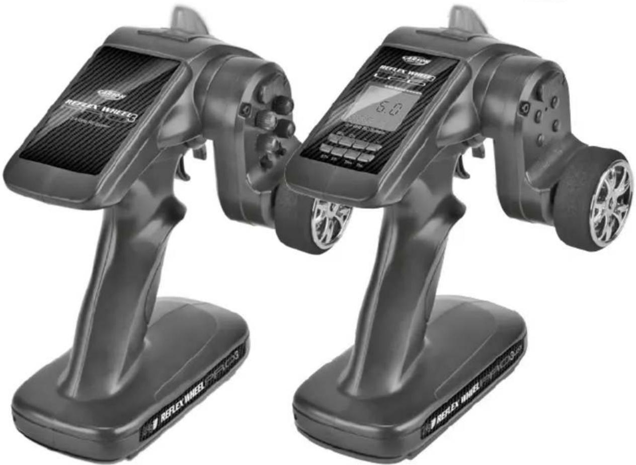
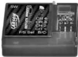
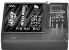
Two identical black-and-white photo of a RELEX WHEEL 2.023 controller with visible branding and control buttons (no text or symbols on the device body)
Sehr geehrter Kunde
natural_image
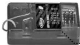
Close-up of a black electronic device with visible internal components and wiring (no readable text or symbols)Empfänger mit BEC
Sender
natural_image
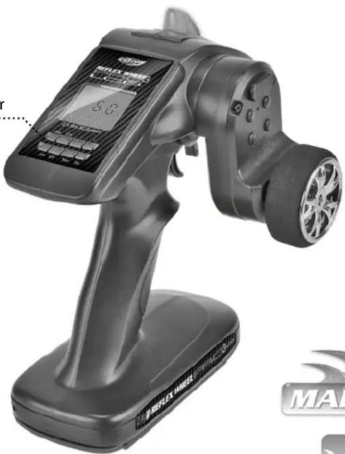
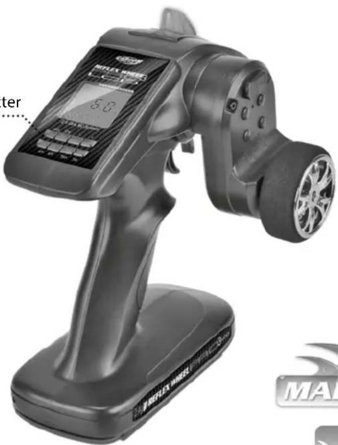
Exterior view of a black reflex wheel controller with digital display and wheels (no text or symbols visible on the device itself)
500500054
Empfänger

500500055

natural_image
Close-up of a mechanical device with visible internal components and wiring (no readable text or symbols)Empfänger mit BEC


500500056

natural_image
Close-up of a vintage computer interface with buttons and a display panel (no readable text or symbols)Empfänger mit BEC
natural_image
Close-up of a black handheld device with internal display panels, showing no visible text or symbols.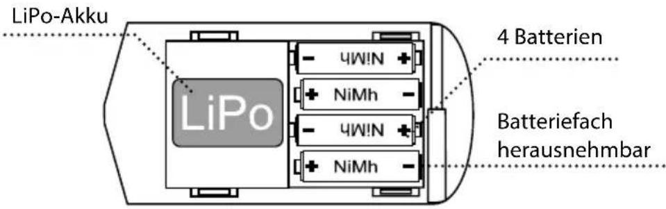
natural_image
Pure electrical circuit lines without any symbolsnatural_image
Technical line drawing of a mechanical device with no visible text or symbolsTrimmung Gas:
natural_image
Two black battery cells with white markings, one larger and one smaller, against a white background (no text or symbols)natural_image
Pure electrical circuit lines without any symbolsnatural_image
Two black-and-white icons: a battery and a fork with crossed blades (no text or symbols)natural_image
Abstract black-and-white graphic with three vertical bars and cloud-like shapes (no text or symbols)natural_image
Symbolic illustration of a water drop with an arrow and cross symbol (no text or numbers)natural_image
Simple line drawing of a battery cell with two smiling faces and a battery pack (no text or symbols)natural_image
Abstract black-and-white icon depicting a document with horizontal lines and a triangular symbol above it, no text or symbols present.natural_image
Close-up of a black electronic device casing with visible internal components and wiring (no readable text or symbols)natural_image
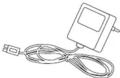
Line drawing of a connected electrical device with a USB cable (no text or symbols)Dear Customer
We congratulate you for buying this CARSON product, which is Designed and manufactured using state of the art technology.
According to our policy of continued development and product improvement, we reserve the right to make changes in specifications regarding equipment, materials and design at any time without notice.
Specifications or designs of the actual product may vary from those shown in this manual or on the box.
The manual forms part of this product. Should you ignore the operating and safety instructions, the warranty will be void.
Keep this guide for future reference.
Limited Warranty
This product is warranted by CARSON against manufacturing defects in materials and workmanship under normal use for 24 months from the date of purchase from authorised franchisees and dealers. In the event of a product defect during the warranty period, return the product along with your receipt as proof of purchase to any CARSON store.
CARSON will, at its option, unless otherwise provided by law:
(a) Correct the defect by repairing the product without charging for parts and labour
(b) Replace the product with one of the same or similar design; or
(c) Refund the purchase price.
All replacement parts and products, and products on which a refund is made, become the property of CARSON. New or reconditioned parts and products may be used in the performance of warranty services.
Repaired or replaced parts and products are warranted for the remainder of the original warranty period. You will be charged for repair or replacement of the product made after the expiration of the warranty period.
The Warranty does not cover:
- Damage or failure caused by or attributable to acts of God, abuse, accident, misuse, improper or abnormal usage, failure to follow instructions, improper installation or maintenance, alteration, lightning or other incidence of excess voltage or current;
- Damage caused by losing control of your Model;
- Any repairs other than those provided by a CARSON Authorised Service Facility;
- Consumables such as fuses or batteries;
- Cosmetic damage;
- Transportation, shipping or insurance costs; or
• Costs of product disposal, installation, set-up service adjustment or reinstallation
This warranty gives you specific legal rights, and you may also have other rights which may vary according to the country of purchase.
Declaration of conformity
Dickie-Tamiya GmbH & Co. KG hereby declares that this model kit with radio, motor, battery and charger is in accordance with the basic requirements of the following European directives: 98/37 EC and 89/336/EEC and other relevant regulations of guideline 1999/5/EC (R&TTE).
The original declaration of conformity can be obtained from the following address:
The explanation of the symbol on the product, packaging or instructions: Electronic devices are
valuable products and should not be disposed of with the household waste when they reach the end of their service life! Help us to protect the environment and respect our resources by delivering this appliance to the relevant recycling point.
We wish you a lots of fun using your CARSON product!
Before using your product carefully read this instructions!
Contents
Preface 20
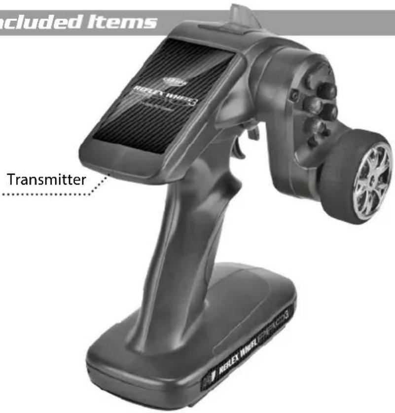
Included Items....22
Advantages/features 2.4 GHz....23
Safety instructions....24
BEC-System/Connections to Receiver for Reflex Wheel Pro3 BEC + Reflex Wheel PRO3 LCD BEC Version....25
Connections to Receiver for Reflex Wheel Pro3 + Reflex Wheel PRO3 LCD Version....26
Equipment for combustion engine....27
Inserting the transmitter batteries / power pack....28
Charging procedure for Li Ion and NiMh rechargeable batteries in the transmitter 28
Adjusting the steering wheel position....28
Function Version REFLEX WHEEL Pro3 LCD 29
Transmitter Handling....30
Functions/Settings 31
Function Version REFLEX WHEEL Pro3.... 33
Transmitter Handling....34
Fail Safe function setting....35
Binding the transmitter and receiver 35
Specifications....35
Battery Safety Guidelines 36
Additional Items....37
Included Items

500500052
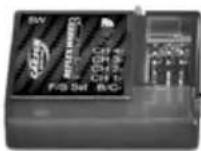
Receiver

500500053
natural_image
Close-up of an electronic device with visible wiring and control panel (no readable text or symbols)Receiver with BEC
Transmitter

500500054

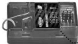
Receiver

500500055

natural_image
Close-up of a black electronic device casing with visible internal components and wiring (no readable text or symbols)Receiver with BEC


500500056
natural_image
Close-up of a mechanical device with labeled components (no readable text or symbols)Receiver with BEC
Features of the 2.4 GHz Remote Controls
The transmitter technology at 2.4 GHz is fundamentally different in some aspects from the technology in the 27.35 and 40 MHz frequency ranges, which up to now have been conventional with remote control models. The previous approach of using a channel determined by plug-in crystals is gone, and the transmitter and receiver work with encoding. The receiver accepts only signals with the coding from its own transmitter. Each signal from the transmitter lasts just milliseconds. Before the next signal, a pause is inserted, which lasts longer than the transmission signal.
Nonetheless, within each second, countless signals are received and evaluated by the receiver. Signals that the receiver recognizes as defective (false encoding, symbol sequences that don't fit the signal schema etc.) are suppressed and are not passed on as control commands.
And as the frequency gets higher, the antennas get shorter.
Remote controls using this transmitter technology or model construction are not subject to fees.
Advantages of the 2.4 GHz Technology
Although the frequency range used is also divided into channels, the user doesn't have to worry about their configuration and has no influence on it anyway.
Because the same encoding is used by the transmitter and receiver, interruption by another receiver or a different transmitter will not occur.
Plug-in crystals are not needed, because the transmitter creates the currently appropriate frequency using a synthesizer circuit, as does the receiver, which determines the right frequency for its encoding.
The old fear of double occupancy of a channel (as when a second transmitter with excessive range override and interrupts a receiver) is a thing of the past. An operator can go ahead and switch on a transmitter and receiver, without negotiating with other model users.
The data transfer capacity is considerably larger than that of previous remote controls, which, for example, has a positive effect on control of the digital servo.
Best of all, at events with a lot of participants, you can always use your own equipment for settings, tests and conversions, because there is almost no limit to the number of active transmitters.
Worth Noting
At these short wavelengths, obstacles can weaken or interrupt the passage of radio waves. That means there should be as few obstacles as possible in the line between the transmission and reception antennas.
The model's receiver antenna must be as far away as possible from electrically conductive parts and very visibly arranged (protruding from the model) to prevent loss of range.
Safety Instructions
If they reach a high speed R/C models can be dangerous and could cause personal injury or damage to property. The appeal of driving an RC model depends on assembling the model accurately and operating it with due care and attention.
- Follow all the warnings, and instructions in this manual.
- Be "Safety Conscious" and use your common sense at all times.
- Remember that operating any R/C model demands skills developed through proper instruction and training – they are not acquired immediately.
- Don't run risks, such as operating your model in adverse weather or when there is a malfunction of which you are aware.
- Respect the rules of the track on which you operate your model.
-
Running your model in the street is very dangerous to both automobile drivers and your model. Avoid running your model in the street.
-
Never aim or direct your model car at any person or animal. These model cars accelerate very quickly and can cause serious physical injury.
- At any time during the operation of your model, should you sense, feel, or observe any erratic operation or abnormality, end your operation. Do not operate it again until you are certain that the problems have been fixed. RC models are not "toys" – safety precautions and forward thinking are essential when operating a remote controlled model!
- Take advantage of the failsafe setting. During a breakdown in signal transmission (such was when transmission voltage is too weak), this setting shifts the model into a control mode that prevents it from running away uncontrolled.
Take your time to read all the way through the pages of this booklet before starting the installation.
Caution
Control of models is impossible with insufficient or no voltage in the transmitter or receiver. A receiver battery that is too weak will move the servo(s) very slowly and that may cause erratic operation of your model. When using a car that operates both the electric
motor and receiver on the same battery, such as a BEC system, you should discontinue operating the car when the top speed becomes sharply reduced, otherwise loss of control will result soon afterwards.
Operating Procedure
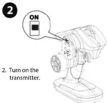
Many publications say that the setup sequence for the transmitter and receiver doesn't play a role anymore with 2.4 GHz sets. However, we recommend sticking to the sequence typical for previous sets.
- Before operation: First turn on the transmitter, then the receiver. Lastly, connect the drive battery to the control unit.
• After operation: Disconnect the battery from the control unit. Turn the receiver off, and then the transmitter.
- Before and after operating the transmitter, make sure that trim settings are as desired and that all checks have been made.
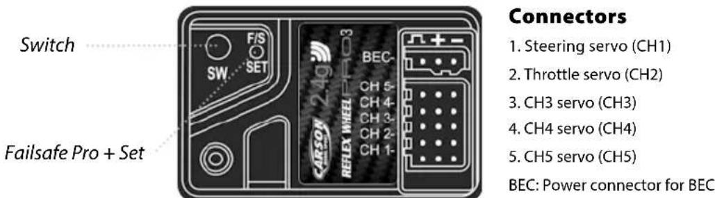
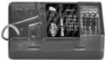
BEC-System/Connections to Receiver for Reflex Wheel PRO3 BEC + Reflex Wheel PRO3 LCD BEC Version
BEC-receiver:
Battery eliminator is installed in the receiver circuitry. The receiver gets supplied with current through the drive battery that runs the engine. NiMH battery from 6 V to 8.4 V can be used for the receiver. Batteries of higher voltage may damage the receiver and servos.
Use only a speed controller which has the exclusive connector for the BEC system.
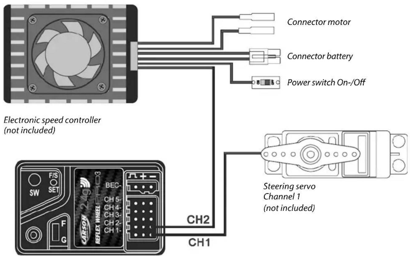
Receiver
Do not connect a separate power supply to the receiver!
AttENTION
Make sure that male and female connectors have the correct polarity!
Connections to Receiver for Reflex Wheel PRO3 + Reflex Wheel PRO3 LCD Version
Battery eliminator is installed in the receiver circuitry.
NiMH battery from 6 V to 11 V can be used for the receiver. Batteries of higher voltage may damage the receiver and servos.
AttENTION! If the input voltage is above 6 V, appropriate high-current servos must be used!
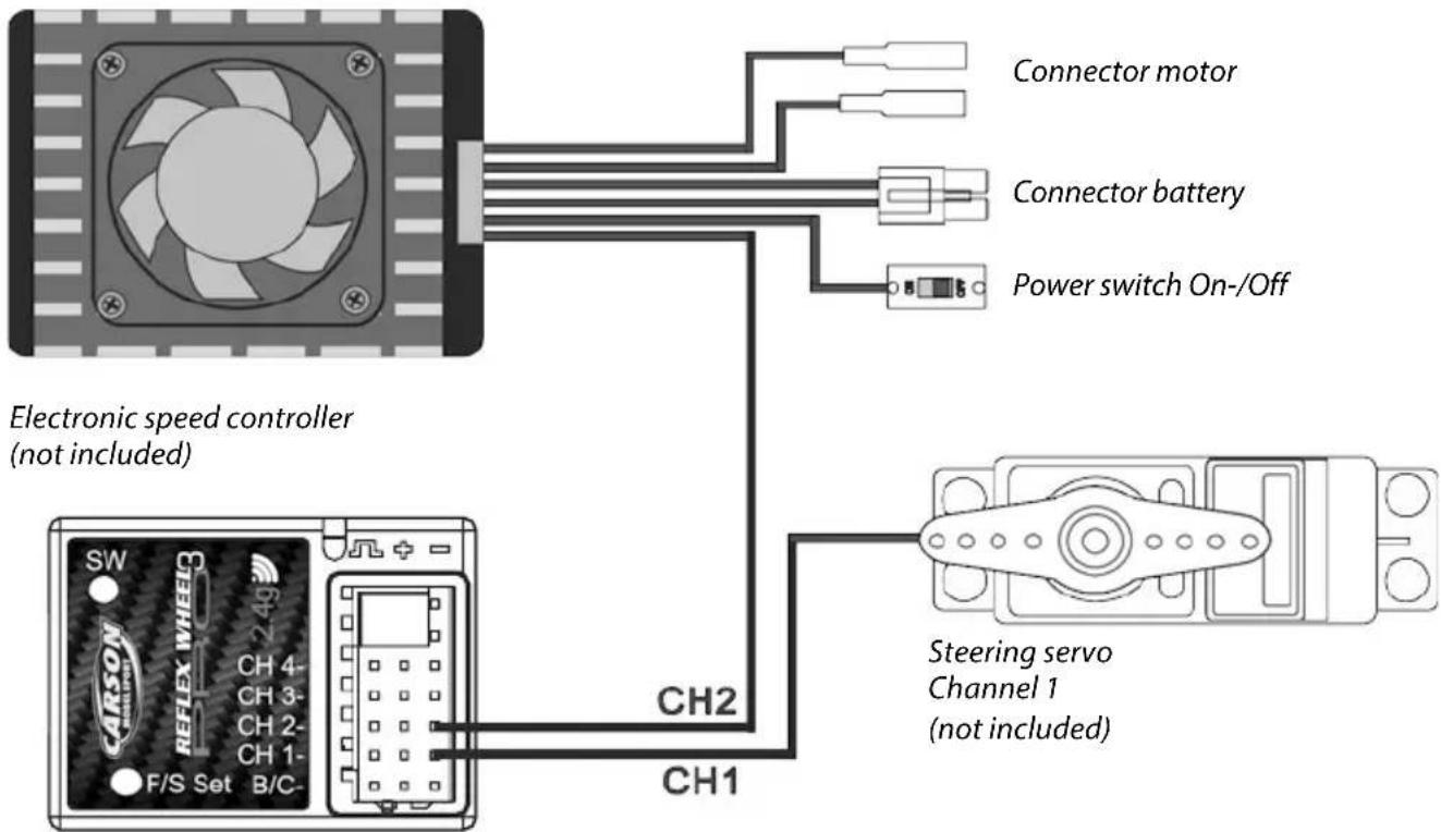
Receiver
Do not connect a separate power supply to the receiver!
AttENTION
Make sure that male and female connectors have the correct polarity!
Equipment for combustion engine
Receiver Batteries and two servos are not included in the kit.
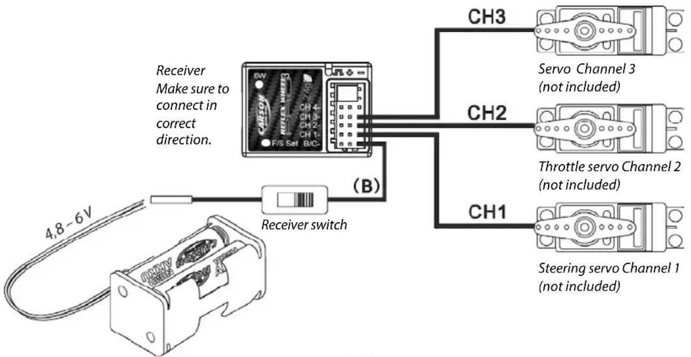
flowchart
graph TD
    A["Device with 4.8–6V power input"] --> B["Receiver switch"]
    B --> C["CH1: Steering servo Channel 1 (not included)"]
    B --> D["CH2: Throttle servo Channel 2 (not included)"]
    B --> E["CH3: Servo Channel 3 (not included)"]
    F["Receiver Make sure to connect in correct direction."] --> A
    style A fill:#f9f,stroke:#333
    style B fill:#ccf,stroke:#333
    style C fill:#cfc,stroke:#333
    style D fill:#fcc,stroke:#333
    style E fill:#cff,stroke:#333
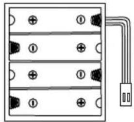
Receiver battery case No. 500503033
AttENTION
When connecting servo leads to the receiver always ensure that the yellow lead/wire is facing inwards (towards the crystal).
Inserting the transmitter batteries
Insert new batteries if the LED display flashes or the buzzer sounds.
- Remove the transmitter battery cover.
- Insert new AA Mignon batteries / rechargeable batteries or the LiPo power pack available as an option.. Pay attention to the correct polarity.
If the LiPo power pack is used and inserted in the transmitter, the current is automatically supplied from the LiPo power pack. If this is removed, the transmitter is supplied from the batteries.
ATTENTION!
Always switch off the transmitter before changing the battery / power pack.
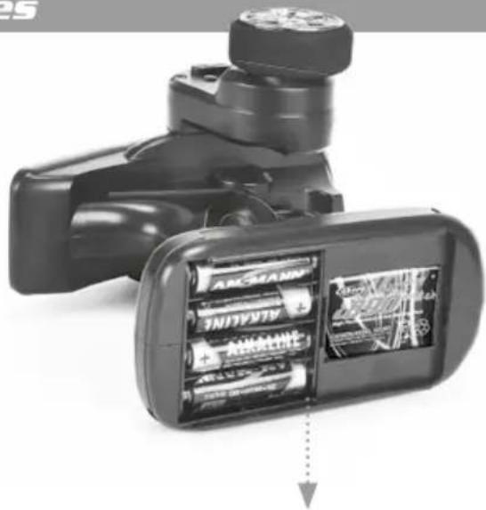
natural_image
Close-up of a black handheld device with battery pack and display screen (no visible text or symbols)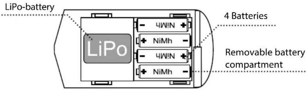
natural_image
Pure electrical circuit lines without any symbolsCharging procedure for Li Ion and NiMh rechargeable batteries in the transmitter
The optionally available rechargeable batteries 500608153 (Li-Ion) or 500609042 (NiMh) can both be charged via the charging socket on the transmitter. These batteries can be charged with a normal 4-cell NiMh charger (e.g. 500606073). If, however, the transmitter is fitted with both rechargeable battery types (Lilon/NiMh) only one of these can be charged. In this case, the Li-Ion battery will always be charged first. If this is removed, you can now charge the 4x NiMh
batteries. The transmitter has an internal Li Ion cut-out as overload protection for the Li Ion battery.
Option: The removable battery compartment provides the added option of charging the NiMh batteries without a charging socket. You will require a separate charger for this.
Please observe the instructions for the charger and the rechargeable batteries!!!
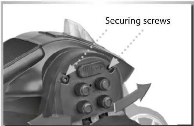
Adjusting the steering wheel position
The steering wheel can be set to any desired position. To adjust it, the two securing screws must be removed. The steering unit can then be moved forwards or backwards to the desired position. Finally re-insert and tighten the two securing screws.
ATTENTION!!!
Tighten the securing screws carefully and do not over-tighten.
Function Version REFLEX WHEEL PRO3 LCD

REFlEx WHEEI PRO3 VERSION
WITHOUT BEC
REFlEx WHEEI PRO3 VERSION
WITH BEC
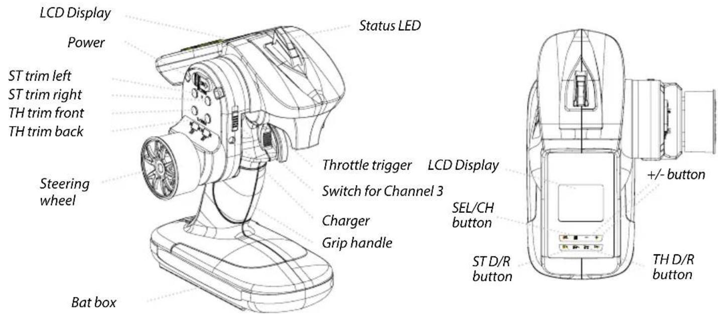
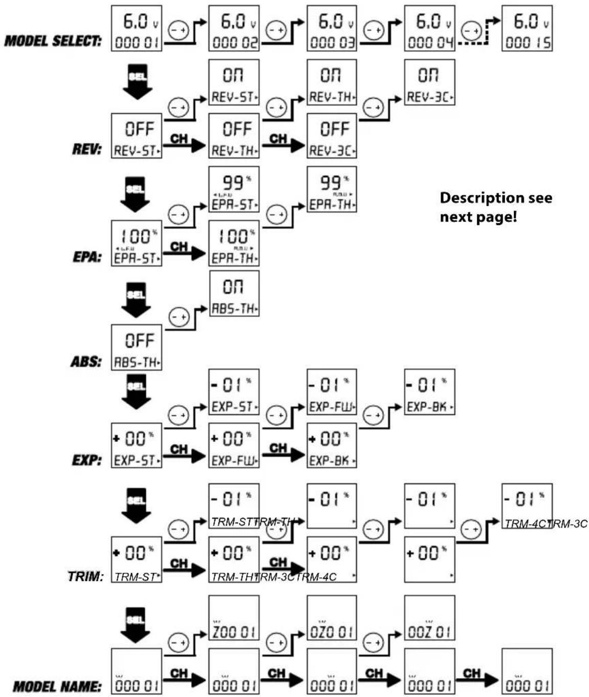
Transmitter Handling
A. THROTTLE TRIGGER

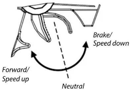
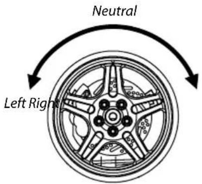
B. STEERING WHEEL
- Push the trigger forward to slow down or brake.
- Pull the trigger backward to accelerate.
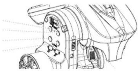
C. TRIM
ST trim left ST trim right TH trim front TH trim back
natural_image
Technical line drawing of a mechanical device with no visible text or symbolsThrottle Trim:
Trim the throttle servo slightly when the trigger is at the neutral position.
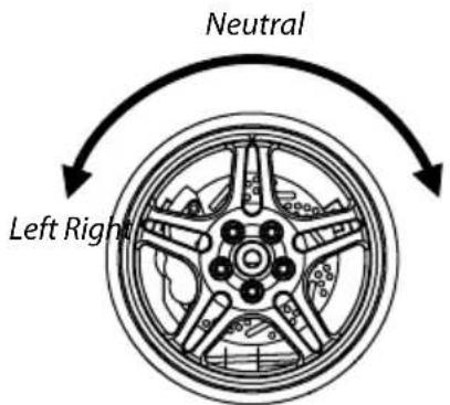
Steering Trim:
If the front wheels do not align straight, use the steering trim to adjust.
RESET / RESTORING THE FACTORY SETTINGS (ONLY FOR LCD VERSION)
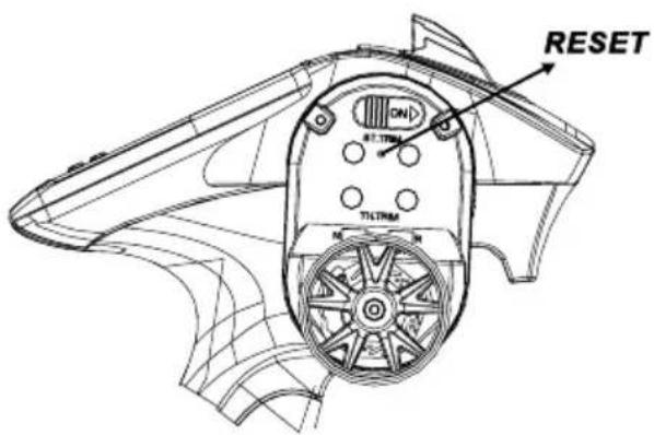
1ST STEP
Delete all values saved in memory (trim/epa/exp):
- Switch on the transmitter.
- Press and hold the RESET button (with a pointed implement).
• A double peep will sound. - Now release the reset button and switch the transmitter on again. All done!!
2ND STEP
Recalibrate the control travels:
- Switch off the transmitter.
- Press and hold the RESET button (with a pointed implement) and switch on the transmitter. The LCD screen is blank.
- Now release the reset button.
- The screen is back to normal and the calibration program has been started.
- Now move the accelerator lever all the way forwards and then all the way backwards. Then turn the steering wheel all the way to the left and then all the way to the right.
- Now switch off the transmitter. Calibration is now complete. All done!!
Functions/Settings

LED FUNCTION DISPLAY
flowchart
graph TD
    A["MODEL SELECT: 6.0 v 000 01"] --> B["+"]
    B --> C["6.0 v 000 02"]
    C --> D["+"]
    D --> E["6.0 v 000 03"]
    E --> F["+"]
    F --> G["6.0 v 000 04"]
    G --> H["+"]
    H --> I["6.0 v 000 15"]

    J["REV: OFF REV-ST"] --> K["+"]
    K --> L["ON REV-ST"]
    L --> M["+"]
    M --> N["ON REV-TH"]
    N --> O["+"]
    O --> P["ON REV-3C"]

    Q["EPS: 100% +L-FU EPA-ST"] --> R["+"]
    R --> S["OFF EPS-TH"]
    S --> T["+"]
    T --> U["OFF EPS-TH"]
    U --> V["99% +L-FU EPA-ST"]
    V --> W["+"]
    W --> X["99% +L-FU EPS-TH"]

    Y["ABS: SEL"] --> Z["+"]
    Z --> AA["ON ABS-TH"]

    AB["EXP: OFF ABS-TH"] --> AC["+"]
    AC --> AD["-01% EXP-ST"]
    AD --> AE["-01% EXP-FW"]
    AE --> AF["-01% EXP-BK"]

    AG["TRIM: +00% EXP-ST"] --> AH["+"]
    AH --> AI["EXP-FW"]
    AI --> AJ["+00% EXP-BK"]

    AK["TRIM: +00% TRM-ST"] --> AL["+"]
    AL --> AM["-01% TRM-ST TRM-TH"]
    AM --> AN["-01% TRM-3C TRM-4C"]

    AO["MODEL NAME: -01% -01% -01% -01% -01% -01% -01% -01% -01% -01% -01% -01% -01% -01% -01% -01% -01% -01% -01% -01% -01% -01% -01% -01% -01% -01"] --> AP["CH"]
    AQ["MODEL NAME: -ZOO 01"] --> AR["+"]
    AR --> AS["-01% ZOO 01"]
    AS --> AT["-01% ZO 01"]
    AT --> AU["-01% ZOZ 01"]
    AU --> AV["-01% ZOZ 01"]
    AV --> AW["-01% ZOZ 01"]
For operation, the transmitter requires 4 AA batteries or rechargeable batteries or the appropriate LiPo power pack.
Once you switch on the On/Off switch, the transmitter is ready for use.
After the transmitter has been switched on, the battery voltage will appear in "V" on the LCD display and, below it, the model name/number last selected will be displayed.
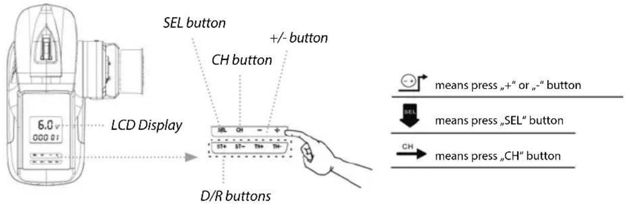
Settings are changed by means of the "SEL", "CH", "+" and "-" buttons.
-
Press +/- to select the desired model. You have the choice of 15 memory spaces. The model number and model name are indicated on the LCD display.
-
Press "SET" to take you to the desired setting. The following functions are available for selection:
a) "REV" setting (reverse direction of servo rotation)
Press the "CH" button and choose between ST, TH or 3CH. Press +/- for normal or reverse.
b) "EPA" setting (servo travel limiter)
Press the "CH" button and choose between TH or ST. To select the direction of rotation, the throttle must be to the front or back with TH, and the steering wheel must be moved left or right with ST. The display shows LFU for left and forwards and RBU for right and brake. The desired value can be set between 0 and 120% by means of +/-
c) ABS setting (anti-blocking system)
Press +/- for ABS on or ABS off.
d) EXP setting (exponential)
Press the "CH" button and choose between ST (steering), FW (forwards) and BK (brake). The desired exponential value can be set between -100% and 100% by means of +/-.
e) MODEL NAME (enter name of model)
Press the CH button until you come to the model name setting. The characters 0 - 9 and A - Z can be entered by means of +/-
- ST-TRIM (trimming the steering)
Press TRIM-ST+ or TRIM-ST- to change the neutral position of the steering servo. It may be adjusted from 0 - 100% right to 0 - 100% left.
TH-TRIMM (trimming the throttle)
Press TRIM-TH+ or TRIM-TH- to change the neutral position of the throttle servo.
It may be adjusted from 0 - 100% throttle to 0 - 100% brake.
TRIM 3C + 4C for channels 3 and 4.
- D/R ST setting (dual rate steering)
Dual rate increases or reduces the servo travel in relation to the travel of the steering wheel/ throttle proportionally over the entire servo path.
Press D/R ST+ or D/R ST- to change the dual rate setting of the steering.
A value between 0 and 100% may be set.
- D/R TH setting (dual rate throttle)
Press D/R TH+ or D/R TH- to change the dual rate setting of the throttle.
A value between 0 and 100% may be set.
- To close the settings, press the SEL button until the battery display reappears.
Then the newly entered values are automatically saved.
Function Version REFLEX WHEEL PRO3
REFlEx WHEEI PRO3 VERSION
WITHOUT BEC
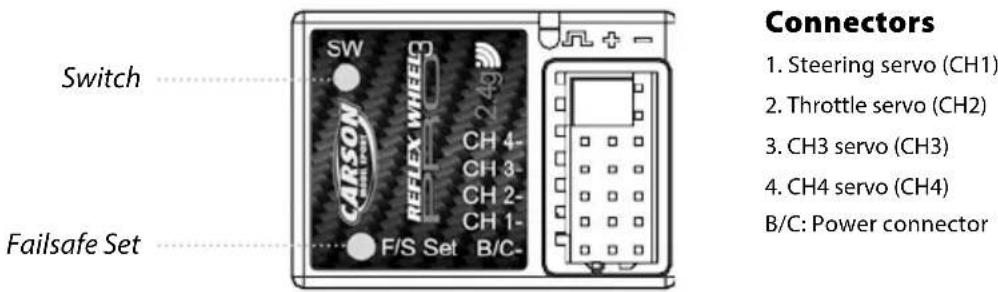
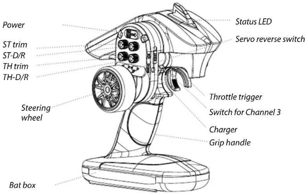
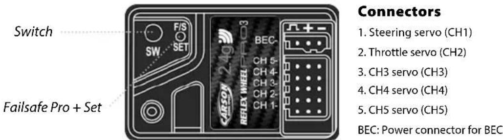
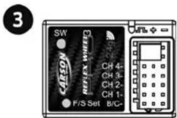
Connectors
- Steering servo (CH1)
- Throttle servo (CH2)
- CH3 servo (CH3)
- CH4 servo (CH4)
B/C: Power connector
REFlEx WHEEL PRO3 VERSION
WITH BEC
Transmitter Handling
A. THROTTLE TRIGGER


B. STEERING WHEEL
- Push the trigger forward to slow down or brake.
- Pull the trigger backward to accelerate.
C. TRIM/SERVO REVERSE
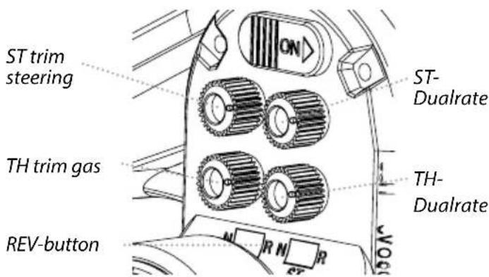
Throttle Trim:
Trim the throttle servo slightly when the trigger is at the neutral position.
Steering Trim:
If the front wheels do not align straight, use the steering trim to adjust.
ST dual rate / TH dual rate:
Dual rate proportionally increases or decreases the servo travel relative to the travel of the steering wheel / accelerator lever over the complete servo travel.
Turn the potentiometers D/R ST or D/R TH to change the dual rate setting of the steering or throttle.
REV switch / servo reverse:
Use the REV switches (TH REV + ST REV) to reverse the direction of rotation of the servos.
RESET / RESTORING THE FACTORY SETTINGS

Switch off the transmitter. Press and hold the RESET button (with a pointed implement) and switch on the transmitter. Now move the accelerator lever all the way forwards and then all the way backwards. Then turn the steering wheel all the way to the left and then all the way to the right. Now switch off the transmitter. Now you can turn the transmitter on again. The factory settings have been restored.
Fail Safe function setting
- Set the TH, ST switches to the normal position.
- Turn on the transmitter and receiver.
- Press the F/S SET button, the LED on the receiver should start flashing rapidly.
- Put the throttle trigger at the brake position, press the F/S SET button, the LED should become solid.
- For electric model, put the throttle trigger at the stop position when you are making the setting.
Reflex Wheel Pro3:
As soon as the receiver/transmitter signal is interrupted, the receiver switches to the default throttle failsafe setting.
Reflex Wheel Pro3 BEC:
The Reflex Wheel Pro2 is fitted with the „Failsafe pro +” system. This system also has integrated low voltage protection. As soon as the voltage is too low for safe operation, the receiver also switches to the default throttle failsafe setting.
Binding the transmitter and receiver
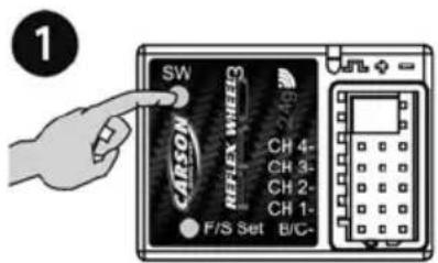
- Turn on the receiver power. Press the SW switch. The receiver's LED should start flashing.
- When the LED on the receiver becomes solid, the binding process is completed.
ATTENTION
Keep the transmitter and receiver not over 40 cm apart when setting and binding.
During the binding process no other transmitter should be operated in the vicinity at the same time!
Specifications
| Transmitter Frequency 2.4 GHz | Power supply DC 4.8 - 6 V= |
| Receiver | Power Supply DC 4.8~6.0 V (Battery box or via BEC-system from driving battery by Version PRO3) |
It is CARSON's policy that we strive to improve the quality of our products. Therefore CARSON may alter specifications of our products at any time without any notice.
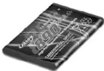
Battery Safety Guidelines
Used correctly, domestic batteries are a safe and dependable source of portable power. Problems can occur if they are misused or abused – resulting in leakage or, in extreme cases, fire or explosion. Here are some simple guidelines to safe battery use designed to eliminate any such problems.
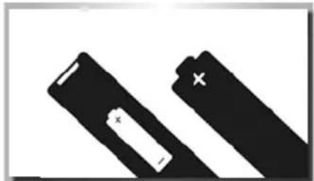
natural_image
Two black battery cells with white markings, one larger and one smaller, against a white background (no text or symbols)Take care to fit your batteries correctly, observing the plus and minus marks on the battery and appliance. Incorrect fitting can cause leakage or, in extreme cases, fire or even an explosion.
natural_image
Pure electrical circuit lines without any symbolsReplace the whole set of batteries at one time, taking care not to mix old and new batteries or batteries of different types, since this can result in leakage or, in extreme cases, fire or even an explosion.
natural_image
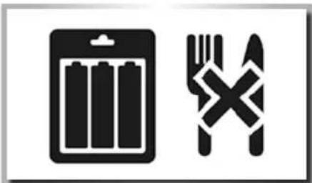
Two black-and-white icons: a battery and a fork crossed with a cross, both without any text or symbols.Store unused batteries in their packaging and away from metal objects which may cause a short-circuit resulting in leakage or, in extreme cases, fire or even an explosion.
natural_image
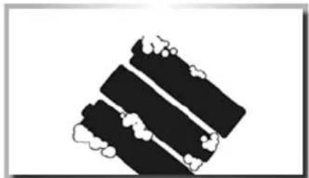
Abstract black-and-white graphic with three vertical bands and cloud-like shapes (no text or symbols)Remove dead batteries from equipment and all batteries from equipment you know you are not going to use for a long time. Otherwise the batteries may leak and cause damage.
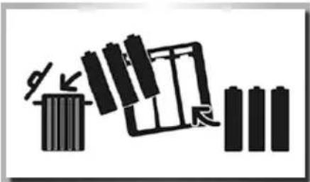
natural_image
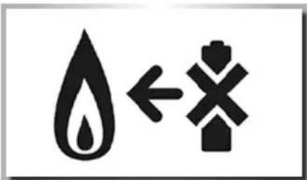
Symbolic illustration of a water drop with an arrow and cross symbol (no text or numbers)Never throw batteries in a fire, this can cause an explosion. Do not put dead batteries with the normal household waste. Deliver them at special collecting institutions.
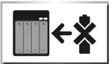
Never attempt to recharge ordinary batteries, either in a charger or by applying heat to them. They may leak, cause fire or even explode. There are special rechargeable batteries which are clearly marked as such.
natural_image
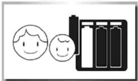
Simple line drawing of a battery cell with two smiling faces and a battery pack (no text or symbols)Supervise children if they are replacing batteries themselves in order to ensure these guidelines are followed.
natural_image
Abstract black-and-white graphic with a triangular shape and horizontal lines, no text or symbols present.Make sure battery compartments are secure.
Additional Items
Receiver Reflex Wheel PRO3 2,4 GHz: 500501533
Receiver Reflex Wheel PRO3 2,4 GHz „wasserfest“: 500501534

Receiver Reflex Wheel PRO3 2,4GHz BEC: 500501535

Receiver Reflex Wheel PRO3 2,4GHz BEC „wasserfest“: 500501536

Transmitter battery Reflex Wheel Pro3 LiPo: 500608153
For transmitter: 4 x Mignon battery 500609042

Charger 400mA: 500606073