
TCG31EBSP - Lawn mower Tanaka - Free user manual and instructions
Find the device manual for free TCG31EBSP Tanaka in PDF.

| Product type | 2-stroke engine brushcutter |
| Brand | Tanaka |
| Model | TCG31EBSP |
| Engine | 2-stroke, 30.8 cm³ (1.88 cu in) |
| Dry weight | 6.7 kg (14.8 lb) |
| Fuel tank capacity | 0.67 L (22.6 fl oz) |
| Fuel | Unleaded gasoline (89 octane) and 2-stroke oil mix, ratio 25:1 to 50:1 |
| Spark plug | Champion RCJ6Y or equivalent |
| Sound pressure level (LpA) | 98.6 dB(A) |
| Guaranteed sound power level | 108 dB(A) |
| Front handle vibration (ISO7916) | 6.3 m/s² |
| Rear handle vibration (ISO7916) | 4.9 to 6.5 m/s² |
| Ignition system | Manual recoil start |
| Cutting tools | Metal blade (25.4 mm bore) or nylon line head (line diameter 2.5 mm) |
| Safety | Blade guard, on/off switch, harness with emergency release |
| Regular maintenance | Cleaning air filter, spark plug, cooling fins, angle gearbox (grease), blade |
| Warranty | Refer to manual or dealer |
| Intended use | Cutting grass, brush and light vegetation |
Frequently Asked Questions - TCG31EBSP Tanaka
User questions about TCG31EBSP Tanaka
0 question about this device. Answer the ones you know or ask your own.
Ask a new question about this device
Download the instructions for your Lawn mower in PDF format for free! Find your manual TCG31EBSP - Tanaka and take your electronic device back in hand. On this page are published all the documents necessary for the use of your device. TCG31EBSP by Tanaka.
USER MANUAL TCG31EBSP Tanaka
natural_image
Technical line drawing of a mechanical clamp or lever assembly (no text or symbols on the diagram itself)SAFETY INSTRUCTIONS AND INSTRUCTION MANUAL
! WARNING
IMPROPER OR UNSAFE use of this power tool can result in death or serious bodily injury!
This manual contains important information about product safety. Please read and understand this manual BEFORE operating the power tool. Please keep this manual available for other users and owners before they use the power tool. This manual should be stored in safe place.
INSTRUCTIONS DE SECURITE ET MODE D'EMPLOI
! AVERTISSEMENT
NOTE: Some units do not carry them.
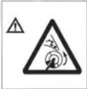
| Symbols⚠ WARNINGThe following show symbols used for the machine. Be sure that you understand their meaning before use. | |||
 | It is important that you read, fully understand and observe the following safety precautions and warnings.Careless or improper use of the unit may cause serious or fatal injury. |  | Shows maximum shaft speed. Do not use the cutting attachment whose max rpm is below the shaft rpm. |
 | Read, understand and follow all warnings and instructions in this manual and on the unit. |  | Gloves should be worn when necessary, e.g., when assembling cutting equipment. |
 | Always wear eye, head and ear protectors when using this unit. |  | Use anti-slip and sturdy footwear. |
 | Be careful of the engine.Engine gets hot by running engine. | 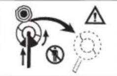 | Blade thrust may occur when the spinning blade contacts a solid object in the critical area. A dangerous reaction may occur causing the entire unit and operator to be thrust violently.This reaction is called blade thrust. As a result, the operator may lose control of the unit which may cause serious or fatal injury. Blade thrust is more likely to occur in areas where it is difficult to see the material to be cut. |
 | Keep all children, bystanders and helpers 15 m away from the unit.If anyone approaches you, stop the engine and cutting attachment immediately. | ||
 | Be careful of thrown objects. |  | Indicate handle location. Do not attach handle above this point. |
Contents
WHAT IS WHAT 3
WARNINGS AND SAFETY INSTRUCTIONS ..... 4
SPECIFICATIONS....6
ASSEMBLY PROCEDURES 7
OPERATING PROCEDURES 10
MAINTENANCE 13
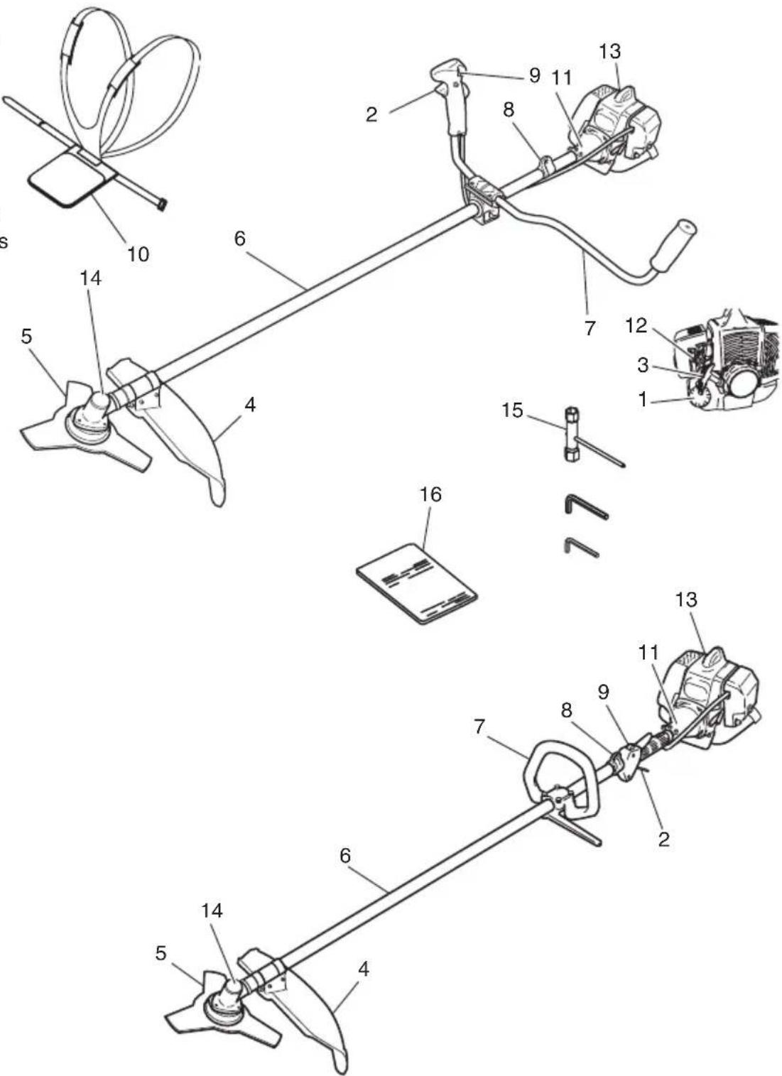
WHAT IS WHAT
Since this manual covers several models, there may be some difference between pictures and your unit. Use the instructions that apply to your unit.
- Fuel cap
- Throttle lever
- Starter handle
- Blade guard
- Cutting attachment
- Drive shaft tube
- Handle
- Suspension eyelet
- Ignition switch
- Harness
- Clutch case
- Choke lever
- Engine
- Angle transmission
- Combi box spanner
- Handling instructions
WARNINGS AND SAFETY INSTRUCTIONS
Operator safety
○ Always wear a safety face shield or goggles.
○ Always wear heavy, long pants, boots and gloves. Do not wear loose clothing, jewelry, short pants, sandals or go barefoot. Secure hair so it is above shoulder length.
○ Do not operate this tool when you are tired, ill or under the influence of alcohol, drugs or medication.
Never let a child or inexperienced person operate the machine.
○ Wear hearing protection. Pay attention to your surroundings. Be aware of any bystanders who may be signaling a problem. Remove safety equipment immediately upon shutting off engine.
○ Wear head protection.
○ Never start or run the engine inside a closed room or building. Breathing exhaust fumes can kill.
○ Keep handles free of oil and fuel.
○ Keep hands away from cutting equipment.
○ Do not grab or hold the unit by the cutting equipment.
○ When the unit is turned off, make sure the cutting attachment has stopped before the unit is set down.
When operation is prolonged, take a break from time to time so that you may avoid possible Hand-Arm Vibration Syndrome (HAVS) which is caused by vibration.
WARNING
● Antivibration systems do not guarantee that you will not sustain Hand-Arm Vibration Syndrome or carpal tunnel syndrome. Therefore, continual and regular users should monitor closely the condition of their hands and fingers. If any symptoms of the above appear, seek medical advice immediately.
- If you are using any medical electric/electronic devices such as a pacemaker, consult your physician as well as the device manufacturer prior to operating any power equipment.
Unit/machine safety
○ Inspect the entire unit/machine before each use. Replace damaged parts. Check for fuel leaks and make sure all fasteners are in place and securely tightened.
○ Replace parts that are cracked, chipped or damaged in any way before using the unit/machine.
○ Make sure the guard is properly attached.
- Keep others away when making carburetor adjustments.
○ Use only accessories as recommended for this unit/machine by the manufacturer.
WARNING
Never modify the unit/machine in any way. Do not use your unit/machine for any job except that for which it is intended.
Fuel safety
○ Mix and pour fuel outdoors and where there are no sparks or flames.
○ Use a container approved for fuel.
☐ Do not smoke or allow smoking near fuel or the unit/machine or while using the unit/machine.
○ Wipe up all fuel spills before starting engine.
○ Move at least 3 m away from fueling site before starting engine.
○ Stop engine before removing fuel cap.
○ Empty the fuel tank before storing the unit/machine. It is recommended that the fuel be emptied after each use. If fuel is left in the tank, store so fuel will not leak.
○ Store unit/machine and fuel in area where fuel vapors cannot reach sparks or open flames from water heaters, electric motors or switches, furnaces, etc.
WARNING
Fuel is easy to ignite or get explosion or inhale fumes, so that pay special attention when handling or filling fuel.
Cutting safety
○ Do not cut any material other than grass and brush.
○ Inspect the area to be cut before each use. Remove objects which can be thrown or become entangled.
☐ For respiratory protection, wear an aerosol protection mask when cutting the grass after insecticide is scattered.
Keep others including children, animals, bystanders and helpers outside the 15 m hazard zone. Stop the engine immediately if you are approached.
○ Always keep the engine on the right side of your body.
○ Hold the unit/machine firmly with both hands.
○ Keep firm footing and balance. Do not overreach.
- Keep all parts of your body away from the muffler and cutting attachment when the engine is running.
○ Keep cutting attachment below waist level.
When relocating to a new work area, be sure to shut off the machine and ensure that all cutting attachments are stopped.
○ Never place the machine on the ground when running.
○ Always ensure that the engine is shut off and any cutting attachments have completely stopped before clearing debris or removing grass from the cutting attachment.
○ Always carry a first-aid kit when operating any power equipment.
Never start or run the engine inside a closed room or building and/or near infl ammable liquids. Breathing exhaust fumes can kill.
Maintenance safety
○ Maintain the unit/machine according to recommended procedures.
○ Disconnect the spark plug before performing maintenance except for carburetor adjustments.
- Keep others away when making carburetor adjustments.
○ Use only genuine Tanaka replacement parts as recommended by the manufacturer.
Transport and storage
○ Carry the unit/machine by hand with the engine stopped and the muffler away from your body.
○ Allow the engine to cool, empty the fuel tank, and secure the unit/machine before storing or transporting in a vehicle.
○ Empty the fuel tank before storing the unit/machine. It is recommended that the fuel be emptied after each use. If fuel is left in the tank, store so fuel will not leak.
○ Store unit/machine out of the reach of children.
○ Clean and maintain the unit carefully and store it in a dry place.
○ Make sure engine switch is off when transporting or storing.
○ When transporting in a vehicle, cover blade with blade cover.
If situations occur which are not covered in this manual, take care and use common sense. Contact your Tanaka dealer if you need assistance. Pay special attention to statements preceded by the following words:
WARNING
Indicates a strong possibility of severe personal injury or loss of life, if instructions are not followed.
CAUTION
Indicates a possibility of personal injury or equipment damage, if instructions are not followed.
NOTE
Helpful information for correct function and use.
CAUTION
Do not disassemble the recoil starter. You may get a possibility of personal injury with recoil spring.
SPECIFICATIONS
| Model | TCG31EBS (P) | TCG31EBS (LP) | |
 | Engine Size (cu. in.) | 1.88 (30.8 ml) | |
 | Spark Plug Champion RCJ6Y or equivalent | ||
 | Fuel TankCapacity (fl . oz) | 22.6 (0.67 l) | |
 | Dry Weight (lbs) 14.8 (6.7 kg) 13.9 (6.3 kg) | ||
 | Sound pressure levelLpA (dB (A))(EN27917) | 98.6 98.4 98.6 98.4 | 98.6 98.6 98.4 |
 | Measured sound power level LwA (dB (A))Guaranteed sound power level LwA (dB (A)) | 105.6 106.5108 108 | 105.6 106.5108 108 |
 | Vibration level (m/s2) (ISO7916)Front handleRear handleLeft handleRight handle | — —— 6.4 6.56.1 5.5 | 6.3 4.94.7 6.1— —— |
NOTE
Equivalent noise level/vibration level are calculated as the time-weighted energy total for noise/vibration levels under various working conditions with the following time distribution: 1/2 Idle, 1/2 racing.
* All data is subject to change without notice.
ASSEMBLY PROCEDURES
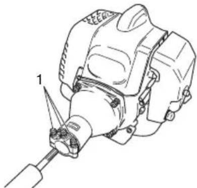
Drive shaft to engine (Fig. 1)
Loosen tube locking bolt (1) about ten turns so that the bolt point will not obstruct drive shaft tube to be inserted. When inserting drive shaft tube, hold the tube locking bolt outward preventing inside fitting from obstructing as well.
Some models may come with the drive shaft already installed.
natural_image
Technical line drawing of a mechanical assembly with a tool and component (no text or symbols)Fig. 1
NOTE
When it is hard to insert drive shaft up to the marked position on the drive shaft tube, turn drive shaft by the cutter mounting end clockwise or counter-clockwise. Tighten tube locking bolt lining up the hole in the shaft tube. Then tighten clamp bolt securely (1).
Installation of handle
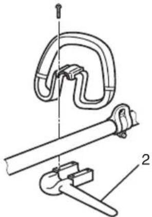
WARNING
When you use steel/rigid blades on straight shaft trimmers or brush cutters, always use a barrier bar (2) and shoulder harness with the loop handle. (Fig. 2)
natural_image
Technical line drawing of a mechanical clamp device with no visible text or symbolsFig. 2
Attach the handle to the drive shaft tube with the angle towards the engine.
Adjust the location to the most comfortable position before operation.
NOTE
If your unit has handle location label on drive shaft tube, follow indication.
Remove the handle bracket (3) from the assembly. (Fig. 3)
Place the handles and attach the handle bracket with four bolts lightly. Adjust to appropriate position. Then attach it firmly with the bolts.
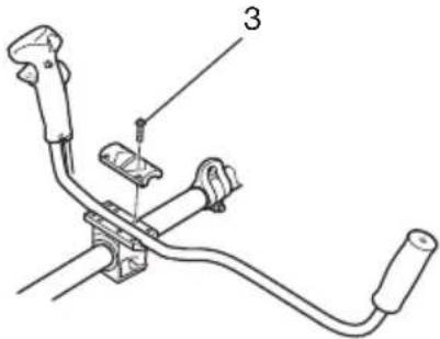
Fig. 3
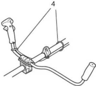
Attach the protection tube to the drive shaft or handle using cord clamps (4). (Fig. 4)
natural_image
Technical line drawing of a mechanical linkage or cable assembly (no text or symbols)Fig. 4
NOTE
If the protection tube is set apart from the handle or pipe, it will be caught by something during operation and it may cause serious injury. Do not set the protection tube apart from the handle or pipe.
Throttle wire / stop cord
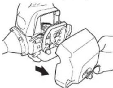
Remove air cleaner cover. (Fig. 5)
natural_image
Mechanical assembly diagram showing a hand operating a motor component with a directional arrow indicating motion (no text or symbols present)Fig. 5
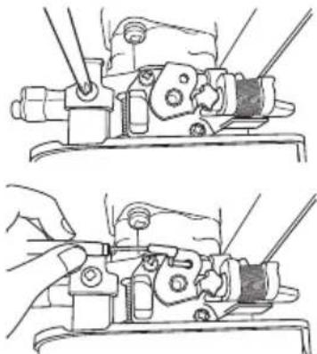
Loosen and remove the screw from the throttle wire holder. (Fig. 6)
natural_image
Technical line drawing showing two mechanical assembly steps with no visible text or symbolsFig. 6
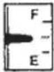
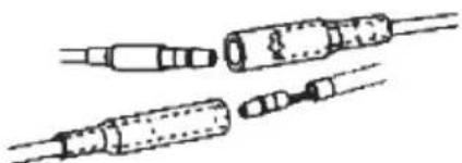
Connect the terminals of the stop cords coming out from the engine and shaft. (Fig. 7)
natural_image
Pure line drawing of two cylindrical electronic components with no text or symbolsFig. 7
Hook the throttle wire end on the throttle of the carburetor.
Make sure that the throttle trigger shown in Fig. 18 has returned to the starting position.
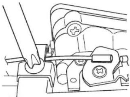
Put the throttle outer end into the groove, and then cover it with the throttle wire holder and fix the holder with the screw. (Fig. 8)
natural_image
Technical line drawing of a mechanical assembly with no visible text or symbolsFig. 8
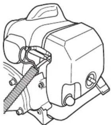
Then, install the cleaner cover. (Fig. 9)
natural_image
Technical line drawing of a mechanical device with gears and housing (no text or symbols)Fig. 9
Fix the protection tube which the stop cords and throttle wire are passing through, on the pipe with the hip pad. Then, as shown in the figure, fix the protection tube on the pipe and handle with the bands in the bag.
After fixing, cut off the extra part of the band not to obstruct the operation. (Fig. 4)
NOTE
If the protection tube is set apart from the handle or pipe, it will be caught by something during operation and it may cause serious injury.
Do not set the protection tube apart from the handle or pipe.
Some models may come with the parts pre-installed.
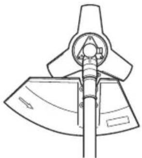
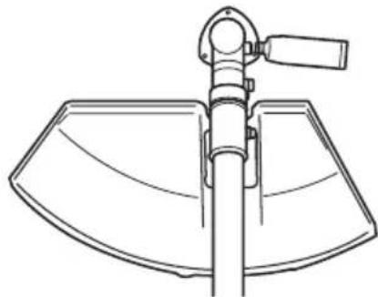
Installation of blade guard (Fig. 10)
The guard bracket already mounted to the drive shaft tube.
Attach the gear case cover with the three screws.
Install the blade guard on drive shaft tube against angle transmission (5). Tighten the guard bracket fi rmly so that the blade guard does not swing or move down during operation.
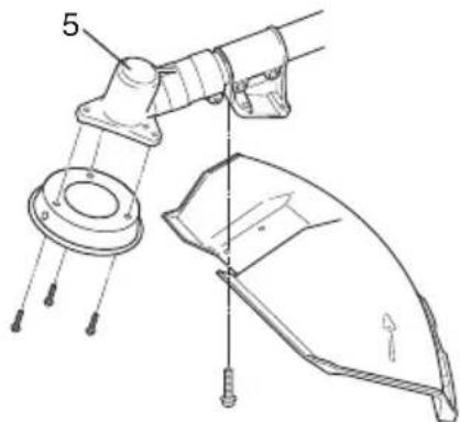
Fig. 10
CAUTION
The blade guard must be in place during operation.
If the blade guard is not in place, there is a possibility of serious injury.
Blade guards are equipped with sharp line limiter. Be careful with handling it.
NOTE
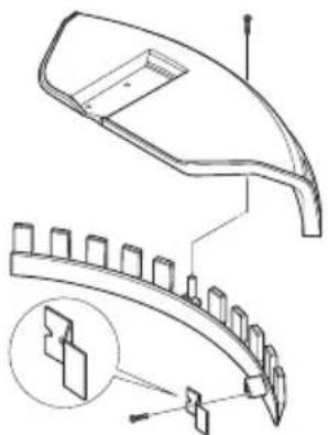
When attaching the guard extension to the blade guard, the sharp line limiter must be removed from the blade guard.
natural_image
Technical line drawing of a curved mechanical component with internal parts and a magnified inset showing internal structure (no text or symbols)Fig. 11
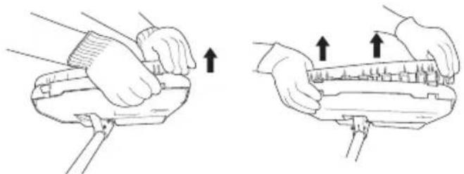
To remove the guard extension, refer to the drawings. Wear gloves as the extension has a sharp line limiter, then push the two square tabs on the guard one by one in order after removed the screw. (Fig. 12)
natural_image
Illustration of two hands using a tool to adjust or install a mechanical component, showing upward movement (no text or symbols)Fig. 12
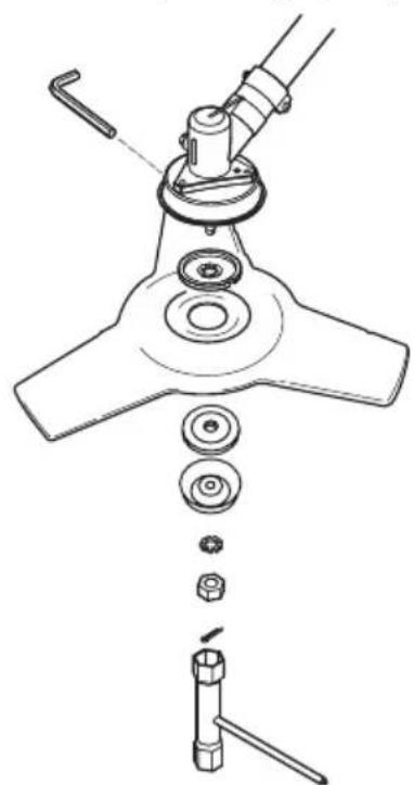
Installation of cutting blade (Fig. 13)
natural_image
Technical line drawing of a mechanical assembly with exploded view (no text or symbols)Fig. 13
When installing a cutting blade, make sure that there are no cracks or any damage in it and that the cutting edges are facing the correct direction.
Align the notch hole of the cutter holder with the hole on the gear case (Top the gear case) and insert the Allen wrench to stop turning. Turn the fi xing nut clockwise and remove the fi xing nut, cutter holder cap, and toothed lock washers.
The installation of the cutting blade is as follows: insert the Allen wrench into the notch hole of the cutter holder and the hole on the gear case. Then, install the cutting blade (check the installing direction, as referring to Fig. 14), the cutter holder cap and toothed lock washers onto the cutter holder in this order. Finally, tighten the fi xing nut securely by turning counterclockwise with the Combi box spanner. (Fig. 13)
natural_image
Technical line drawing of a mechanical impeller or blade assembly (no text or symbols)Fig. 14
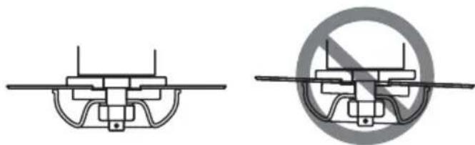
CAUTION
- When installing the cutting blade, set its center hole to the convex part of the cutter holder and hold it with the concave surface of the cutter holder cap. Then, tighten the fixing nut to prevent the cutting blade from being eccentric. (Fig. 15)
After installing the cutting blade, be sure to remove the Allen wrench and Combi box spanner.
● Before operation, make sure the blade has been properly installed.
● Cutter holder cap under a cutting blade, check it for wear or cracks before operation. If any damage or wear is found, replace it, as it is an article of consumption.
natural_image
Two technical diagrams showing mechanical components with no visible text or symbols, one with a diagonal line and the other with a circle containing a crossed-out symbol (no text or labels present)Fig. 15
NOTE
The blade must be retained with a new cotter pin each time installed. (Fig. 13)
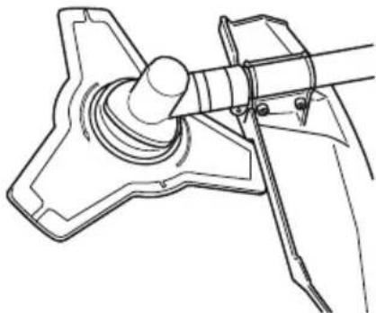
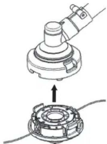
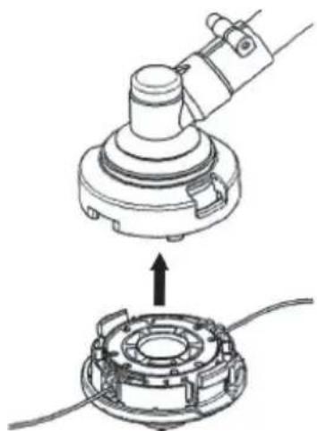
Installation of nylon head (Fig. 16)
Attach cutter holder (6) to the gear case. Insert an Allen wrench into the hole in the gear case to attach nylon head (7) by turning it clockwise.
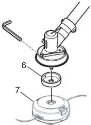
Fig. 16
NOTE
Since cutter holder cap is not used here, keep it for next metal blade use.
OPERATING PROCEDURES
Fuel (Fig. 17)
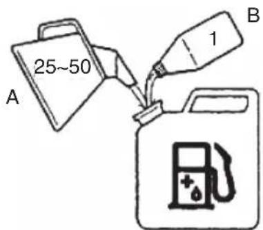
Fig. 17
WARNING
● The brush cutter is equipped with a two-stroke engine. Always run the engine on fuel, which is mixed with oil.
Provide good ventilation, when fueling or handling fuel.
● Fuel contains highly flammable and it is possible to get the serious personal injury when inhaling or spilling on your body. Always pay attention when handling fuel. Always have good ventilation when handling fuel inside building.
Fuel
○ Always use branded 89 octane unleaded gasoline.
○ Use genuine two-cycle oil or use a mix between 25:1 to 50:1, please consult the oil bottle for the ratio or Tanaka dealer.
○ Only for the state of California at 50:1.
If genuine oil is not available, use an anti-oxidant added quality oil expressly labeled for air-cooled 2-cycle engine use (JASO FC GRADE OIL or ISO EGC GRADE). Do not use BIA or TCW (2-stroke water-cooling type) mixed oil.
○ Never use multi-grade oil (10 W/30) or waste oil.
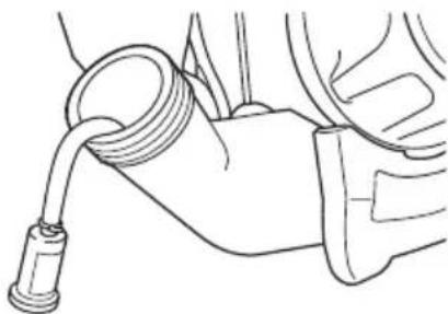
○ Always mix fuel and oil in a separate clean container.
Always start by fi ling half the amount of fuel, which is to be used. Then add the whole amount of oil. Mix (shake) the fuel mixture. Add the remaining amount of fuel.
Mix (shake) the fuel-mix thoroughly before filling the fuel tank.
Fueling
WARNING
● Always shut off the engine before refueling. ● Slowly open the fuel tank, when filling up with fuel, so that possible over-pressure disappears.
● Tighten the fuel cap carefully, after fueling.
● Always move the brush cutter at least 10 ft (3 m) from the fueling area before starting.
● Always wash any spilled fuel from clothing immediately with soap.
● Be sure to check for any fuel leakage after refueling.
Before fueling, clean the tank cap area carefully, to ensure that no dirt falls into the tank. Make sure that the fuel is well mixed by shaking the container, before fueling.
Starting (Fig. 18)
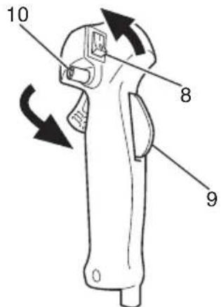
Fig. 18
CAUTION
Before starting, make sure the cutting attachment does not touch anything.
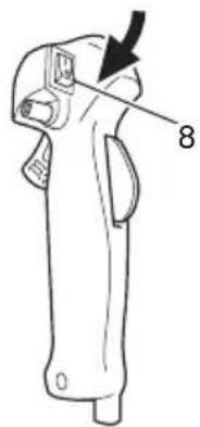
- Slide ignition switch (8) to RUN position. (Fig. 18)
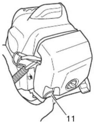
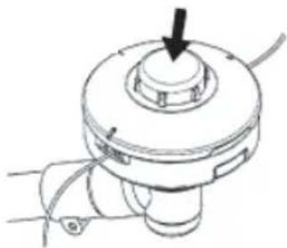
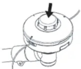
* Push priming bulb (11) several times so that fuel flows through return pipe. (Fig. 19)
natural_image
Technical line drawing of a mechanical component with labeled part 11 (no text or symbols beyond label)Fig. 19
-
With the safety trigger (9) (if so equipped) pressed, pull throttle trigger and push throttle lock (10). Then slowly release the throttle trigger first, then the safety trigger. This will lock the throttle in starting position.
-
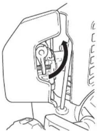
Set choke lever to "START" position. (Fig. 20)
natural_image
Mechanical assembly diagram showing a rotating component with an arrow indicating rotation (no text or symbols present)Fig. 20
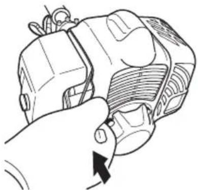
- Pull recoil starter briskly, taking care to keep the handle in your grasp and not allowing it to snap back. (Fig. 21)
natural_image
Hand holding a mechanical component with a directional arrow indicating rotation (no text or symbols)Fig. 21
- When you hear the engine want to start, return choke lever to RUN position (open). Then pull recoil starter briskly again.
NOTE
If engine does not start, repeat procedures from 2 to 5.
- After starting engine, pull throttle trigger to release throttle lock. Then allow the engine about 2–3 minutes to warm up before subjecting it to any load.
Cutting (Fig. 22, 23, 24)
When cutting, operate engine at over 6500 rpm. Extended time of use at low rpm may wear out the clutch prematurely.
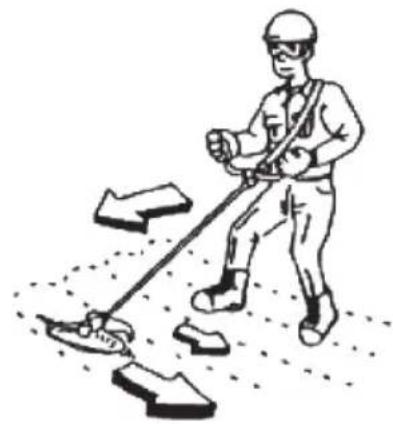
○ Cut grass from right to left.
○ Blade thrust may occur when the spinning blade contacts a solid object in the critical area.
A dangerous reaction may occur causing the entire unit and operator to be thrust violently. This reaction is called blade thrust. As a result, the operator may lose control of the unit which may cause serious or fatal injury. Blade thrust is more likely to occur in areas where it is difficult to see the material to be cut.
○ Wear the harness as shown in the figure. The blade turns counter-clockwise, therefore, be advised to operate the unit from right to left for efficient cutting. Keep onlookers out of working area at least 50 ft (15 m).
natural_image
Illustration of a worker in safety gear using a tool to move down a path with directional arrows (no text or symbols)Fig. 22

natural_image
Line drawing of a person wearing safety harness and helmet, holding equipment (no text or symbols)Fig. 23
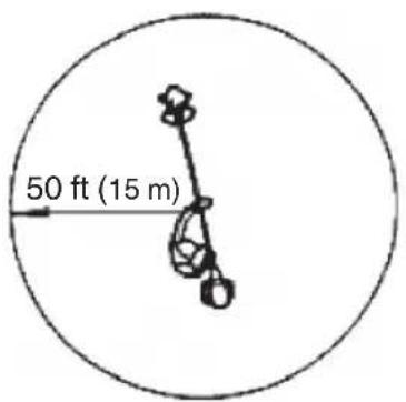
Fig. 24
NOTE
Press the quick release button or pull emergency release flap in the event of emergency. (Fig. 25)
How to use the shoulder harness
Wear the shoulder harness on your shoulder as shown Fig. 23 and hook it on the hanger of the machine. Adjust the length of the shoulder harness to the most comfortable position. (Fig. 23)
To remove the machine from the shoulder harness, hold the main pipe of the machine firmly by one hand and then remove the hook (13) of the shoulder harness from the hanger (14). (Fig. 25-a)
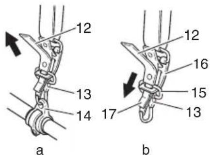
Fig. 25
How to reinstall the hook after using the emergency release pinch
It needs to go through the buckle (15) of the hook (13) to the metal plate (16) on the harness and go through the plate (17) of the emergency release pinch to the metal plate (16) on the harness. (Fig. 25-b)
After installing the buckle onto the harness, pull the hook (13) and make sure the hook (13) is securely fixed on the harness, then hook it to the hanger (14). (Fig. 25-a)
WARNING
- When using the machine, wear the shoulder harness and hold the machine correctly with both hands.
If you feel that there is something dangerous, separate the brush cutter from your body by pulling the emergency release pinch (12) of the harness to the direction of the arrow shown in Fig. 25-a.
- If the cutting attachment should strike stones or other debris, stop the engine and make sure that the attachment and related parts are undamaged. When grass or vines wrap around attachment, stop engine and attachment and remove them.
NOTE
If you pull the emergency release pinch without holding the machine, the machine will fall to your feet. Pull the emergency release pinch while holding the main pipe of the machine by one hand.
Before operation, make sure that the emergency release pinch on the shoulder harness is working properly.
Stopping (Fig. 26)
Decrease engine speed and run at an idle for a few minutes, then turn off ignition switch (9).
natural_image
Line drawing of a mechanical device with a labeled part (8), no text or symbols presentFig. 26
WARNING
A cutting attachment can injure while it continues to spin after the engine is stopped or power control is released. When the unit is turned off, make sure the cutting attachment has stopped before the unit is set down.
How to use nylon head
When cutting, operate engine at over 6500 rpm. Extended time of low rpm may wear out the clutch prematurely.
This product is designed so that it will stop cutting when the nylon line becomes 6-5/16" (16 cm) or longer.
WARNING
A cutting attachment can injure while it continues to spin after the engine is stopped or power control is released. When the unit is turned off, make sure the cutting attachment has stopped before the unit is set down.
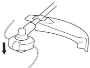
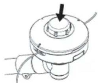
Set the engine speed as low as possible and tap the Head on the ground. (Fig. 27) Also, you can extend nylon line with hands but the engine must be completely stopped. (Fig. 28)
Adjust nylon line to proper length 4-11/32" - 5-1/2" (11-14 cm) before each operation.
natural_image
Line drawing of a mechanical clamp or lever mechanism with a downward arrow indicating motion (no text or symbols)Fig. 27
natural_image
Technical line drawing of a mechanical component with a central hub and cable (no text or symbols)Fig. 28
MAINTENANCE
MAINTENANCE, REPLACEMENT OR REPAIR OF THE EMISSION CONTROL DEVICES AND SYSTEMS MAY BE PERFORMED BY ANY NON-ROAD ENGINE REPAIR ESTABLISHMENT OR INDIVIDUAL.
Carburetor adjustment (Fig. 29)
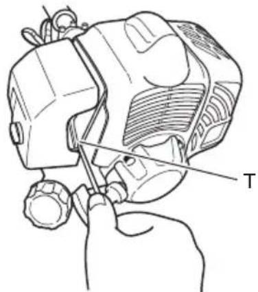
Fig. 29
WARNING
● The cutting attachment may be spinning during carburetor adjustments.
● Never start the engine without the complete clutch cover and tube assembled! Otherwise the clutch can come loose and cause personal injuries.
In the carburetor, fuel is mixed with air. When the engine is test run at the factory, the carburetor is basically adjusted. A further adjustment may be required, according to climate and altitude. The carburetor has one adjustment possibility:
T = Idle speed adjustment screw.
Idle speed adjustment (T)
Check that the air fi Iter is clean. When the idle speed is correct, the cutting attachment will not rotate. If adjustment is required, close (clockwise)
the T-screw, with the engine running, until the cutting attachment starts to rotate. Open (counterclockwise) the screw until the cutting attachment stops. You have reached the correct idle speed when the engine runs smoothly in all positions well below the rpm when the cutting attachment starts to rotate.
If the cutting attachment still rotates after idle speed adjustment, contact your Tanaka dealer.
NOTE
Standard Idle rpm is 2200–2800 rpm.
WARNING
When the engine is idling the cutting attachment must under no circumstances rotate.
Air fi Iter (Fig. 30)
The air fi Iter must be cleaned from dust and dirt in order to avoid:
○ Carburetor malfunctions
○ Starting problems
○ Engine power reduction
○ Unnecessary wear on the engine parts
○ Abnormal fuel consumption
Clean the air fi Iter daily or more often if working in exceptionally dusty areas.
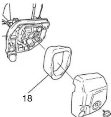
Fig. 30
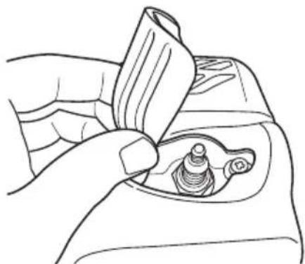
Cleaning the air filter
Remove the air filter cover and the filter (18). Rinse it in warm soap suds. Check that the fi liter is dry before reassembly. An air fi liter that has been used for some time cannot be cleaned completely. Therefore, it must regularly be replaced with a new one. A damaged fi liter must always be replaced.
Fuel filter (Fig. 31)
Drain all fuel from fuel tank and pull fuel filter line from tank. Pull filter element out of holder assembly and rinse element in warm water with detergent.
Rinse thoroughly until all traces of detergent are eliminated. Squeeze, do not wring, away excess water and allow element to air dry.
NOTE
If element is hard due to excessive dirt buildup, replace it.
natural_image
Line drawing of a hand holding a medical catheter or tube, no text or symbols presentFig. 31
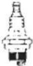
Spark plug (Fig. 32)
The spark plug condition is influenced by:
○ An incorrect carburetor setting
○ Wrong fuel mixture (too much oil in the gasoline)
○ A dirty air fi Iter
○ Hard running conditions (such as cold weather)
These factors cause deposits on the spark plug electrodes, which may result in malfunction and starting diffi culties. If the engine is low on power, diffi cult to start or runs poorly at idling speed, always check the spark plug fi rst. If the spark plug is dirty, clean it and check the electrode gap. Re-adjust if necessary. The correct gap is 0.024" (0.6 mm). The spark plug should be replaced after about 100 operation hours or earlier if the electrodes are badly eroded.
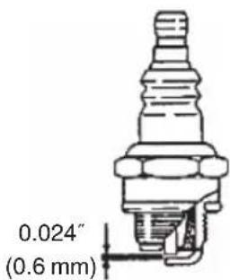
Fig. 32
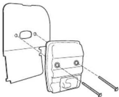
Muffler (Fig. 33)
Remove the muffler and clean out any excess carbon from the exhaust port or muffler inlet every 100 hours of operation.
natural_image
Technical line drawing of a mechanical component with screws and a housing (no text or symbols)Fig. 33
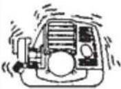
Cylinder (Engine cooling) (Fig. 34)
The engine is air cooled, and air must circulate freely around engine and over cooling fi ns on cylinder head to prevent overheating.
Every 100 operating hours, or once a year (more often if conditions require), clean fins and external surfaces of engine of dust, dirt and oil deposits which can contribute to improper cooling.
natural_image
Line drawing of a hand holding a small object with a curved handle, no text or symbols presentFig. 34
NOTE
Do not operate engine with engine shroud or muffler guard removed as this will cause overheating and engine damage.
Angle transmission (Fig. 35)
Check angle transmission or angle gear for grease level about every 50 hours of operation by removing the grease fi ller plug on the side of angle transmission.
If no grease can be seen on the fl anks of the gears, fi ll the transmission with quality lithium based multipurpose grease up to 3/4. Do not completely fi ll the transmission.
natural_image
Technical line drawing of a mechanical device with a central shaft and curved blades (no text or symbols)Fig. 35
Blade
WARNING
Wear protective gloves when handling or performing maintenance on the blade. (Fig. 36)
natural_image
Technical line drawing of a mechanical assembly with no visible text or symbolsFig. 36
○ Use a sharp blade. A dull blade is more likely to snag and thrust. Replace the fastening nut if it is damaged and hard to tighten.
When replacing blade, purchase one recommended by Tanaka, with a 25.4 mm (one inch) fitting hole.
When installing a saw blade, always face the stamped side up. In the case of a 3 tooth blade, it can be used on either side.
○ Use the correct blade for the type of work.
○ When replacing blades, use appropriate tools.
When cutting edges become dull, re-sharpen or file as shown in the illustration. Incorrect sharpening may cause excessive vibration.
○ Discard blades that are bent, warped, cracked, broken or damaged in any way.
NOTE
When sharpening blade it is important to maintain an original shape of radius at the base of the tooth to avoid cracking.
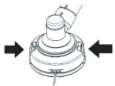
Nylon head
Nylon line replacement
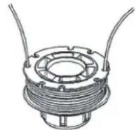
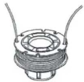
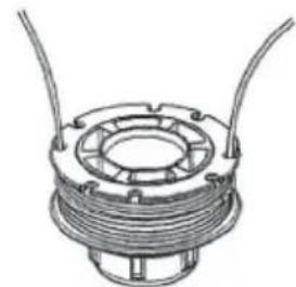
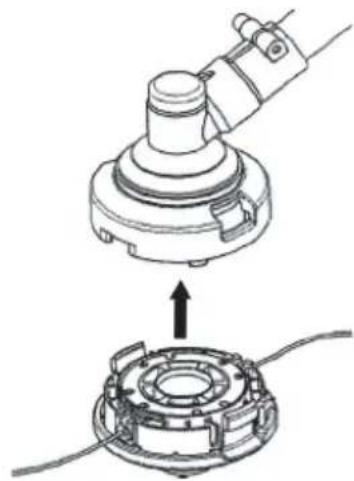
○ Remove the cutting body cap by pushing inward the locking tabs on the side of the nylon head (Fig. 37). Take out the spool, hook the new nylon line into the hole of the spool, then wind it around the spool in two stages (Fig. 38).
When the nylon line has been wound around the spool, temporarily fasten it in the opening of the spool at about 4" (10 cm) from the end. (Fig. 39) Then thread the nylon line through the hole on the side of the nylon head and place the cutting body cap in reverse order of the cap removal. Pull the right and left nylon lines until they are secured about 4-11/32" - 5-1/2" (11-14 cm) from the end. (Fig. 42)
natural_image
Diagram of a mechanical component with directional arrows indicating movement or force (no text or symbols)Fig. 37
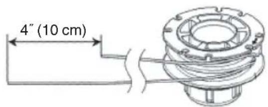
Fig. 38
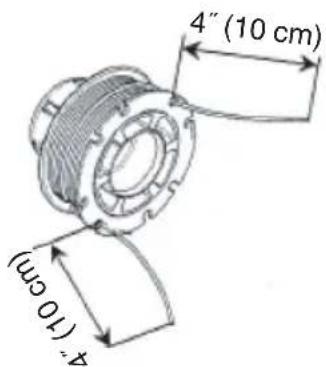
Fig. 39
natural_image
Technical line drawing of a coiled motor or coil assembly with two leads (no text or symbols)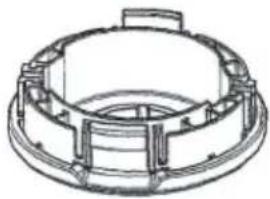
natural_image
Technical line drawing of a mechanical component with concentric rings and mounting flanges (no text or symbols)Fig. 40
natural_image
Technical illustration of a mechanical assembly showing a rotating component and its cross-section view (no text or symbols)Fig. 41
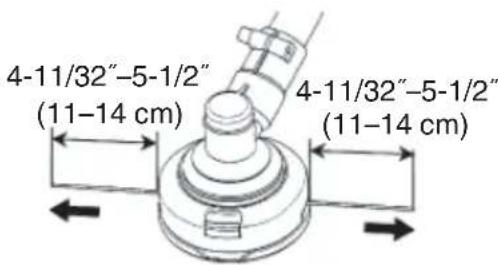
Fig. 42
NOTE
☐ The nylon head is designed for nylon lines with an outer diameter of 0.1" (2.5 mm). Do not use nylon lines with a different outer diameter.
○ Make sure that the right and left nylon lines are of equal length since vibrations will otherwise increase.
Maintenance schedule
Below you will find some general maintenance instructions. For further information please contact your Tanaka dealer.
Daily maintenance
○ Clean the exterior of the unit.
○ Check that the harness is undamaged.
○ Check the blade guard for damage or cracks. Change the guard in case of impacts or cracks.
☐ Check that the cutting attachment is properly centred, sharp, and without cracks. An off-centre cutting attachment induces heavy vibrations that may damage the unit.
○ Check that the cutting attachment nut is sufficiently tightened.
○ Make sure that the blade transport guard is undamaged and that it can be securely fitted.
○ Check that nuts and screws are sufficiently tightened.
Weekly maintenance
○ Check the starter, especially the cord and return spring.
○ Clean the exterior of the spark plug.
○ Remove it and check the electrode gap. Adjust it to 0.024" (0.6 mm), or change the spark plug.
○ Clean the cooling fins on the cylinder and check that the air intake at the starter is not clogged.
○ Check that the angle gear is filled with grease up to 3/4.
○ Clean the air filter.
Monthly maintenance
○ Rinse the fuel tank with gasoline.
○ Clean the exterior of the carburetor and the space around it.
○ Clean the fan and the space around it.
SIGNIFICATION DES SYMBOLES
PRÉCAUTIONS ET CONSIGNES DE SÉCURITÉ
natural_image
Technical line drawing of a mechanical assembly with a tool inserted (no text or symbols)Fig. 1
REMARQUE
natural_image
Technical line drawing of a mechanical clamp device with no visible text or symbolsFig. 2
Fig. 3
natural_image
Technical line drawing of a mechanical linkage or cable assembly (no text or symbols)Fig. 4
REMARQUE
natural_image
Mechanical assembly diagram showing a motor and gear assembly with a directional arrow (no text or labels)Fig. 5
natural_image
Technical line drawing showing two mechanical assembly steps with hands adjusting components (no text or symbols)Fig. 6
natural_image
Pure diagram of two cylindrical electronic components with no text or symbolsFig. 7
natural_image
Technical line drawing of a mechanical assembly with no visible text or symbolsFig. 8
natural_image
Technical line drawing of a mechanical device with no visible text or symbolsFig. 9
natural_image
Technical line drawing of a curved mechanical component with internal parts and an inset view showing a bracket detail (no text or symbols)Fig. 11
natural_image
Illustration of two hands performing a tool manipulation or repair operation (no text or symbols present)Fig. 12
natural_image
Technical line drawing of a mechanical assembly with exploded view (no text or symbols)Fig. 13
natural_image
Technical line drawing of a mechanical impeller or blade assembly (no text or symbols)Fig. 14
IMPORTANT
natural_image
Two technical diagrams showing mechanical components with no visible text or symbols, one with a diagonal line and the other with a circle (no text or symbols present)Fig. 15
REMARQUE
Fig. 16
REMARQUE
natural_image
Technical line drawing of a mechanical component with no visible text or symbolsFig. 19
natural_image
Mechanical component diagram showing a piston and crankshaft mechanism (no text or symbols)Fig. 20
natural_image
Line drawing of a hand holding a mechanical component with a directional arrow indicating rotation (no text or symbols)Fig. 21
natural_image
Illustration of a person using a tool to move a large number of shoes, with arrows indicating movement direction (no text or symbols)Fig. 22

natural_image
Line drawing of a person wearing safety harness and helmet, holding equipment (no text or symbols)Fig. 23
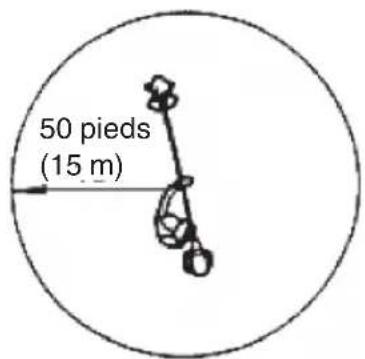
Fig. 24
REMARQUE
natural_image
Line drawing of a mechanical tool with an arrow pointing to a section (no text or symbols)Fig. 26
ATTENTION
natural_image
Mechanical assembly diagram showing a lever mechanism with a curved handle and rotating component (no text or symbols)Fig. 27
natural_image
Technical line drawing of a mechanical device with a central hub and cable (no text or symbols)Fig. 28
ENTRETIEN
L'ENTRETIEN, LE REMPLACEMENT OU LA RÉPARATION DES DISPOSITIFS ET SYSTÈMES DE CONTRÔLE DE L'ÉCHAPPEMENT PEUVENT ÊTRE EFFECTUÉS PAR N'IMPORTE QUEL ATELIER DE RÉPARATION OU MÉCANICIEN DE MOTEUR NON AUTOMOBILE.
natural_image
Technical line drawing of a mechanical component being adjusted with a tool (no text or symbols present)Fig. 29
ATTENTION
natural_image
Line drawing of a mechanical joint or connector with a coiled cable or spring (no text or symbols)Fig. 31
Bougie (Fig. 32)
Fig. 32
Silencieux (Fig. 33)
natural_image
Technical line drawing of a mechanical component with screws and a housing (no text or symbols)Fig. 33
natural_image
Line drawing of a hand holding a small object with a bandage, no text or symbols presentFig. 34
REMARQUE
natural_image
Line drawing of a mechanical device with a lever and curved blades (no text or symbols)Fig. 35
Lame
ATTENTION
natural_image
Technical line drawing of a mechanical component with no visible text or symbolsFig. 36
natural_image
Diagram of a mechanical component with directional arrows indicating movement or force (no text or symbols)Fig. 37
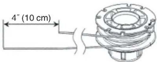
Fig. 38
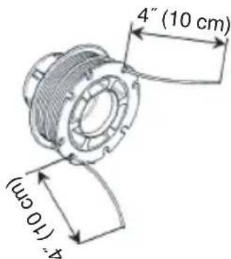
Fig. 39
natural_image
Technical line drawing of a mechanical component with coiled spring and two protruding wires (no text or symbols)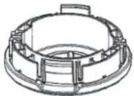
natural_image
Technical line drawing of a mechanical component with concentric rings and mounting flanges (no text or symbols)Fig. 40
natural_image
Technical illustration of a mechanical assembly with a hand operating a workpiece above a circular component (no text or symbols present)Fig. 41
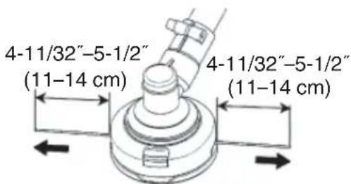
Fig. 42
REMARQUE
natural_image
Technical line drawing of a mechanical assembly with a tool and component (no text or symbols)Fig. 1
NOTA
natural_image
Technical line drawing of a mechanical clamp device with no visible text or symbolsFig. 2
natural_image
Mechanical linkage diagram showing a lever system with two components and a numbered label (4), no text or symbols present.Fig. 4
NOTA
natural_image
Technical line drawing of a mechanical assembly with a hand operating a component (no text or symbols present)Fig. 5
natural_image
Technical line drawing showing two views of a mechanical assembly with hands operating (no text or symbols present)Fig. 6
natural_image
Illustration of two cylindrical electronic components with leads, shown in line style without any text or symbols.Fig. 7
natural_image
Technical line drawing of a mechanical assembly with no visible text or symbolsFig. 8
natural_image
Technical line drawing of a mechanical device with no visible text or symbolsFig. 9
natural_image
Technical line drawing of a curved mechanical component with internal components and an inset view (no text or symbols)Fig. 11
natural_image
Illustration of two hands using a tool to adjust or install a mechanical component, showing upward movement (no text or symbols)Fig. 12
natural_image
Technical line drawing of a mechanical assembly with exploded view (no text or symbols)Fig. 13
natural_image
Technical line drawing of a mechanical impeller or blade assembly (no text or symbols)Fig. 14
PRECAUCIÓN
natural_image
Two technical diagrams showing mechanical components with no visible text or symbols, one with a circular absence and the other with a diagonal line (no text or symbols present)Fig. 15
NOTA
Fig. 16
NOTA
natural_image
Technical line drawing of a mechanical component with no visible text or symbolsFig. 19
natural_image
Mechanical assembly diagram showing a rotating component with an arrow indicating motion (no text or symbols)Fig. 20
natural_image
Line drawing of a hand holding a mechanical component with a black arrow indicating rotation (no text or symbols)Fig. 21
natural_image
Illustration of a worker in safety gear using a tool to move or walk (no text or symbols present)Fig. 22

natural_image
Line drawing of a person wearing safety harness and helmet, holding equipment (no text or symbols)Fig. 23
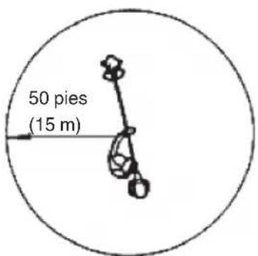
Fig. 24
NOTA
natural_image
Line drawing of a mechanical clamp or lever mechanism with a curved handle and base, showing motion direction (no text or symbols)Fig. 27
natural_image
Technical line drawing of a mechanical component with a central hub and mounting base (no text or symbols)Fig. 28
MANTENIMIENTO
Fig. 29
ADVERTENCIA
natural_image
Line drawing of a hand holding a cable with a bulb, no text or symbols presentFig. 31
Bujía (Fig. 32)
Fig. 32
natural_image
Technical line drawing of a mechanical component with screws and a housing (no text or symbols)Fig. 33
natural_image
Line drawing of a hand holding a small object with a curved handle, no text or symbols presentFig. 34
NOTA
natural_image
Technical line drawing of a mechanical device with a lever and curved blades (no text or symbols)Fig. 35
Cuchilla
ADVERTENCIA
natural_image
Technical line drawing of a mechanical assembly with no visible text or symbolsFig. 36
natural_image
Mechanical component diagram showing a knob and lever mechanism with directional arrows (no text or symbols)Fig. 37
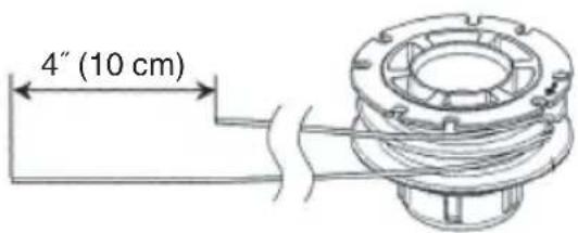
Fig. 38
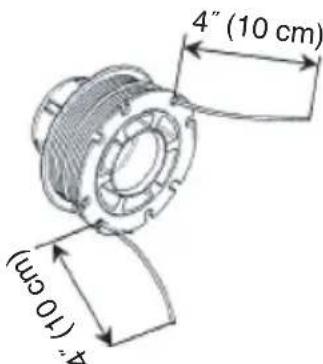
Fig. 39
natural_image
Technical line drawing of a mechanical component with coiled spring and two protruding rods (no text or symbols)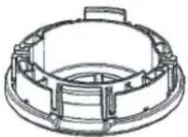
natural_image
Technical line drawing of a mechanical component with concentric rings and mounting flanges (no text or symbols)Fig. 40
natural_image
Technical illustration of a mechanical assembly with a top view showing a rotating component and a bottom view showing a circular component (no text or symbols present)Fig. 41
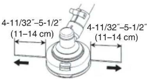
Fig. 42
NOTA
natural_image
Line drawing of a quill pen in an inkwell (no text or symbols)
| Item No. | Part Name Q'TY | |
| 1 Ball bearing, 6001 2 | ||
| 2 Oil seal TC type 12x28x7 1 | ||
| 3 Oil seal TC type 12x22x7 1 | ||
| 4 Retaining ring RTW-28 1 | ||
| 5 Crank case set 1 | ||
| 5-3 Spring type straight pin slotted 3x10 2 | ||
| 5A Crank Case Ass'y 1 | ||
| 6 Gasket, crankcase 1 | ||
| 7 Cross recessed pan head screw S M5x25 4 | ||
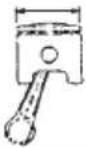
| 8-1 Piston 1 | ||
| 8-2 Ring, piston | 2 | |
| 8-3 Pin, piston 9x31 | 1 | |
| 8-4 Ring, snap | 2 | |
| 8-7 Crank shaft assy | 1 | |
| 9 | Woodruff key 3x3.7x10 | 1 |
| 10 | Cylinder | 1 |
| 11 | Gasket, cylinder | 1 |
| 12 Torx socket head cap screw M5x0.8x20 | 4 | |
| 13 Spark plug | 1 | |
| 14-1 | Rotor, magnet | 1 |
| 14-2 | Coil comp | 1 |
| 15 Conical nut M8xP1.25 | 1 | |
| 16 Washer, ig coil 4.2x10x1 2 | ||
| 17 | Spacer, ig coil | 2 |
| 18 | Torx socket head cap screw PS M4x0.7x20 with nylok | 2 |
| 19 Wire, lead | 1 | |
| 20 Wire, lead-ground | 1 | |
| 21 | Sleeve, leadwire | 1 |
| 22 Clutch assy | 1 | |
| 23 Clutch bolt | 2 | |
| 24 | Wave washer 10 | 2 |
| 25 Washer 8.2x18x1.2 | 2 | |
| 26 | Fan cover for back pack | 1 |
| 27 | Spring type staight pin slotted 3x10 | 2 |
| 28 | Cross recessed pan head screw PS M5x25 | 4 |
| 29B | Muffler assy rear exhaust with catalyst | 1 |
| 30 Heat shield | 1 | |
| 31 | Gasket, muffler | 1 |
| 32 | Torx socket button head screw M5x0.8x60 | 2 |
| 33 | Cross recessed pan head screw PS M5x16 | 2 |
| 34 | Muffler cover | 1 |
| 35 | Gasket, insulator | 1 |
| 36 | Insulator for diaphragm carb. | 1 |
| 37 | Torx socket button head screw PS M5x0.8x22 | 2 |
| 38 Gasket, carburetor 1 | ||
| 39 | Carburetor assy, diaphragm | 1 |
| 40 | Gasket, cleaner | 1 |
| 41-1 | Base, cleaner | 1 |
| 41-2 | Primer pump assy. | 1 |
| 41-3 | Pipe, pump (0.045m) | 1 |
| 41-4 | Clip, pipe | 1 |
| 41-5 | Clip, pipe | 1 |
| 41-6 | Pipe, return | 1 |
| 42 | Torx socket button head screw M5x0.8x60 | 2 |
| 43 Spit back shield | 1 | |
| 44 | Air filter element | 1 |
| 45-1 | Cover, cleaner | 1 |
| 45-2 | Knob, cover | 1 |
| 46 Top cover | 1 | |
| 47 Spacer, top cover | 1 | |
| 48 | Cross recessed pan head screw PS M5x20 | 1 |
| Item No. | Part Name Q'TY | |
| 49B-1-1 | Fuel tank | 1 |
| 49B-1-2 | Fuel filter comp | 1 |
| 49B-1-3 | Pipe , suction (0.150m) | 1 |
| 49B-1-4 | Clip , pipe | 1 |
| 49B-1-5 | Valve Ass'y | 1 |
| 49B-1-5-1 | Valve , fuel cap | 1 |
| 49B-1-5-2 | Cap, holder | 1 |
| 49B-1-5-3 | Holder, valve | 1 |
| 49B-1-5-4 | Element, valve | 1 |
| 49B-1-5-5 | Pipe , valve assy | 1 |
| 49B-2 | Fuel Cap Ass'y | 1 |
| 49B-2-1 | Fuel cap | 1 |
| 49B-2-2 | Gasket , fuel cap | 1 |
| 49B-2-3 | Holder, Gasket | 1 |
| 49B-2-4 | Strap, fuel cap | 1 |
| 50 Engine stand | 1 | |
| 51 | Torx socket flange screw M5×0.8×16 | 2 |
| 52 | Cross recessed pan head screw PS M5×20 | 1 |
| 53 | Recoil starter assy 1 | |
| 54 Pulley assy | 1 | |
| 55 | Cross recessed pan head screw PS M5×25 | 4 |
| 56 Stay ,throttle cable | 1 | |
| 57 | Cross recessed pan head screw ST4.2×12 | 1 |
TCG31EBS (P)
| Item No. | Part Name Q'TY | |
| 101 | Gear case ass'y 1 | |
| 102 | Stop ring 1 | |
| 103 | Stop ring (Φ10) 1 | |
| 104 | Bearing (6000-2RS/P5) 2 | |
| 105 | Pinion 1 | |
| 106 | Screw (M5×25) 1 | |
| 107 | Washer 2 | |
| 108 | Bolt (M6×12) 2 | |
| 109 | Gear case 1 | |
| 110 | Safety guard 1 | |
| 111 | Screw (M5×12) | 5 |
| 112 | Bearing (6000/P5) | 1 |
| 113 | Gear | 1 |
| 114 | Gear shaft | 1 |
| 115 | Bearing (6002-2RS/P5) | 1 |
| 116 | Stop ring (Φ32) 1 | |
| 117 | Holder A | 1 |
| 118 | Holder B | 1 |
| 119 | Nut Cover | 1 |
| 120 | Washer 1 | |
| 121 | Left nut (M10×1.25) | 1 |
| 122 | Pin (2×16) | 2 |
| 123 | Washer5 1 | |
| 124 | Clutch drum comp | 1 |
| 125 | Stop ring (Φ35) | 1 |
| 126 | Bearing(6202-2RS/P5) | 1 |
| 127 | Stop ring (Φ15) 1 | |
| 128 | Clutch case | 1 |
| 128A | Clutch case Ass'y | 1 |
| 129 | Rubber cover | 1 |
| 130 | Screw (M5×25) | 2 |
| 131 | S. washer (Φ5) | 4 |
| Item No. | Part Name Q'TY | |
| 132 | Washer(Φ5) | 4 |
| 133 Clamp B | 1 | |
| 134 Clamp A | 1 | |
| 135 Screw (M6×20) 4 | ||
| 136 S.washer (Φ6) | 4 | |
| 137 | Washer (Φ6) | 4 |
| 138 Tool kit | 1 | |
| 139 Hanger | 1 | |
| 140 Clamp | 1 | |
| 141 | Screw (M5×20) 1 | |
| 142 Nut (M5) | 1 | |
| 143 kit | 1 | |
| 144 | Bushing cover | 6 |
| 145 | Oil-bearing (8×14×14) | 6 |
| 146 Drive shaft (1526mm) | 1 | |
| 147 | Pipe (26×1.5×1500) | 1 |
| 147A | Pipe Ass'y 1 | |
| 148 Belt assy | 1 | |
| 149 Wire clamp band | 2 | |
| 150 Screw(M6×40) | 4 | |
| 151 Cap,lower | 1 | |
| 152 Rubber cover | 1 | |
| 153 Nut (M6) | 4 | |
| 154 Bracket 1 | ||
| 155 Nut M6 | 4 | |
| 156 Cap,upper | 1 | |
| 157 | Screw(M6×25) | 4 |
| 158 Handle (Bike) | 1 | |
| 159 Grip | 1 | |
| 160 Bushing | 1 | |
| 161 inner spanner S=5 | 1 | |
| 162 Screw (ST2.9×10) | 1 | |
| Item No. | Part Name Q'TY | |
| 163 | Button | 1 |
| 164 | Spring | 1 |
| 165 | Stop Switch | 1 |
| 166 | Locking pin | 1 |
| 167 | Throttle lever | 1 |
| 168 | Spring | 1 |
| 169 | Box,right | 1 |
| 169A | R Switch Ass'y | 1 |
| 170 | BOLT ST3.5×16 | 2 |
| 171 | Screw(M5×30) | 3 |
| 172 | Cable comp | 1 |
| 173 | Stop wire | 1 |
| 174 | Safety lever | 1 |
| 175 | Spring | 1 |
| 176 | Box,left | 1 |
| 177 | Blade | 1 |
| 178 | Blade cover | 1 |
| 179 | Safety guard bracket | 1 |
| 180 | Tube | 1 |
| 181 | Safety guard 1 | |
| 182 | Spacer | 2 |
| 183 | Screw (M5×16) 4 | |
| 184 | Screw (ST4.2×16) | 1 |
| 185 | Guard | 1 |
| 186 | Screw (ST4.2×12) | 2 |
| 187 | Blade | 1 |
| 188 | Cutting head assy | 1 |
| 189 | Nylon cutter head guard | 1 |
| 190 | Oil seal | 1 |
| 191 | Inner spanner S=4 | 1 |
| 192 | Spark plug sleeve | 1 |
TCG31EBS (LP)
| Item No. | Part Name Q'TY | |
| 101 | Gear case ass'y 1 | |
| 102 | Stop ring 1 | |
| 103 | Stop ring (Φ10) 1 | |
| 104 | Bearing (6000-2RS/P5) 2 | |
| 105 | Pinion 1 | |
| 106 | Screw (M5×25) 1 | |
| 107 | Washer 2 | |
| 108 | Bolt (M6×12) 2 | |
| 109 | Gear case 1 | |
| 110 | Safety guard 1 | |
| 111 | Screw (M5×12) 5 | |
| 112 | Bearing (6000/P5) | 1 |
| 113 | Gear | 1 |
| 114 | Gear shaft 1 | |
| 115 | Bearing (6002-2RS/P5) | 1 |
| 116 | Stop ring (Φ32) 1 | |
| 117 | Holder A | 1 |
| 118 | Holder B | 1 |
| 119 | Washer | 1 |
| 120 | Left nut (M10×1.25) | 1 |
| 121 | Pin (2×16) | 2 |
| 122 | Blade | 1 |
| 123 | Washer5 | 1 |
| 124 | Clutch drum comp | 1 |
| 125 | Stop ring (Φ35) | 1 |
| 126 | Bearing (6202-2RS/P5) | 1 |
| 127 | Stop ring (Φ15) 1 | |
| 128 | Clutch case | 1 |
| 128A | Clutch case Ass'y | 1 |
| 129 | Rubber cover | 1 |
| 130 | Screw (M5×25) 2 | |
| 131 | S. washer (Φ5) | 4 |
| Item No. | Part Name Q'TY | |
| 132 Washer (Φ5) 4 | ||
| 133 Clamp B | 1 | |
| 134 Clamp A | 1 | |
| 135 Screw (M6×20) 4 | ||
| 136 S.washer (Φ6) | 4 | |
| 137 | Washer (Φ6) | 4 |
| 138 Tool kit | 1 | |
| 139 Hanger | 1 | |
| 140 Clamp | 1 | |
| 141 | Screw (M5×20) 1 | |
| 142 Nut (M5) | 3 | |
| 143 kit | 1 | |
| 144 Bushing cover | 6 | |
| 145 Oil-bearing (8×14×14) | 6 | |
| 146 | Drive shaft (1526mm Korea) | 1 |
| 147 | Pipe (26×1.5×1500) | 1 |
| 147A | Pipe Ass'y (Euro) | 1 |
| 148 inner spanner S=5 | 1 | |
| 149 Handle Ass'y | 1 | |
| 150 Nylon cutter head guard | 1 | |
| 152 Inner spanner S=4 | 1 | |
| 153 Screw (M5×14) 1 | ||
| 154 Clamp | 1 | |
| 155 Box,right | 1 | |
| 155A | Loop Switch Ass'y | 1 |
| 156 Rubber cover | 1 | |
| 157 | Clamp | 1 |
| 158 Stop button comp | 1 | |
| 159 Tine | 1 | |
| 160 Spring | 1 | |
| 161 Spring | 1 | |
| 162 Safety lever | 1 | |
| Item No. | Part Name Q'TY | |
| 163 | Spring | 1 |
| 164 | Throttle lever | 1 |
| 165 | Cable comp | 1 |
| 166 | Tube | 1 |
| 167 | Screw (M5×20) 1 | |
| 168 | Screw (M5×30) 3 | |
| 169 | Box,left 1 | |
| 170 | Oil seal | 1 |
| 171 | Bushing | 1 |
| 172 | Blade cover | 1 |
| 173 | Safety guard bracket | 1 |
| 175 | Safety guard 1 | |
| 176 | Spacer | 2 |
| 177 | Screw (M5×16) 4 | |
| 178 | Screw (ST4.2×16) | 1 |
| 179 | Guard | 1 |
| 180 | Screw (ST4.2×12) | 2 |
| 181 | Blade | 1 |
| 182 | Spark plug sleeve | 1 |
| 183 | Belt assy | 1 |
| 184 | Cutting head assy | 1 |
WARNING:
Some dust created by power sanding, sawing, grinding, drilling, and other construction activities contains chemicals known to the State of California to cause cancer, birth defects or other reproductive harm. Some examples of these chemicals are:
- Lead from lead-based paints,
- Crystalline silica from bricks and cement and other masonry products, and
- Arsenic and chromium from chemically-treated lumber.
Your risk from these exposures varies, depending on how often you do this type of work. To reduce your exposure to these chemicals: work in a well ventilated area, and work with approved safety equipment, such as those dust masks that are specially designed to filter out microscopic particles.