TCG 24EAP2(SL) - Lawn mower Tanaka - Free user manual and instructions
Find the device manual for free TCG 24EAP2(SL) Tanaka in PDF.


| Brand | Tanaka |
| Model | TCG 24EAP2(SL) |
| Product type | Brushcutter / Edger |
| Category | Lawn mower |
| Engine | 2-stroke, 24 cm³ (estimated) |
| Fuel | Gasoline-oil mixture (25:1 to 50:1) |
| Dry weight | Approximately 5.5 kg |
| Cutting tool | Semi-automatic nylon line head (ø2.4-3.0 mm) or metal blade (3/4 teeth, ø229-305 mm) |
| Max rotation speed | Approximately 8000 rpm (depending on tool) |
| Idle speed | 2800-3200 rpm |
| Starting | Recoil starter |
| Ignition | Electronic |
| Spark plug | Gap 0.6 mm, with interference suppressor |
| Fuel tank | Capacity not specified |
| Main functions | Grass cutting, brush clearing, edge trimming |
| Safety perimeter | 15 meters around the user |
| Required protective equipment | Helmet, visor/goggles, hearing protection, gloves, long clothing, non-slip shoes |
| Harness | Included depending on model (recommended) |
| Maintenance | Cleaning air filter, fuel filter, spark plug, lubricating flexible shaft (every 20h), greasing gearbox (every 50h) |
| Spare parts | Available at Tanaka dealer (blades, heads, filters, spark plugs, etc.) |
Frequently Asked Questions - TCG 24EAP2(SL) Tanaka
User questions about TCG 24EAP2(SL) Tanaka
0 question about this device. Answer the ones you know or ask your own.
Ask a new question about this device
Download the instructions for your Lawn mower in PDF format for free! Find your manual TCG 24EAP2(SL) - Tanaka and take your electronic device back in hand. On this page are published all the documents necessary for the use of your device. TCG 24EAP2(SL) by Tanaka.
USER MANUAL TCG 24EAP2(SL) Tanaka
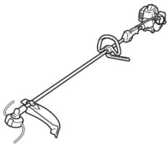
TCG 22EAP2 (SL) / TCG 22EAP2 (S) TCG 22EAP2 (SLD) / TCG 22EAP2 (LB) TCG 24EAP2 (SL) / TCG 24EAP2 (S) TCG 27EAP2 (SL) / TCG 27EAP2 (S)
natural_image
Technical line drawing of a mechanical clamp or measuring tool with a lever and base mount (no text or symbols)TCG22EAP2 (SL)

en Handling instructions
de Bedienungsanleitung
fr Mode d'emploi
it Istruzioni per l'uso
nl Gebruiksaanwijzing
es Instrucciones de manejo
pt Instruções de uso
el Οδηγίες χειρισμού
pl Instrukcja obsługi
hu Kezelési utasítás
cs Návod k obsluze
tr Kullanım talimatları
ro Instructiuni de utilizare



2

3


natural_image
Illustration of a worker in protective gear using a tool to clean or dig through a tree stump, with warning symbols (no text present)
natural_image
Diagram of a vehicle with directional arrows and aircraft illustrations, no text or symbols present
natural_image
Diagram of a spacecraft with orbital paths and warning symbol (no text labels)4

5

6

7

8

9
natural_image
Technical line drawing of a mechanical assembly with labeled component '16' (no text or symbols beyond label)1

natural_image
Illustration of three types of cable connectors (no text or symbols)0
12 13 14


natural_image
Diagram of a device handle with two arrows pointing to the top panel (no text or symbols present)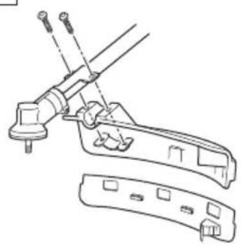
natural_image
Technical line drawing of a mechanical clamp or bracket assembly (no text or symbols)

natural_image
Technical line drawing of a mechanical assembly with no visible text or symbols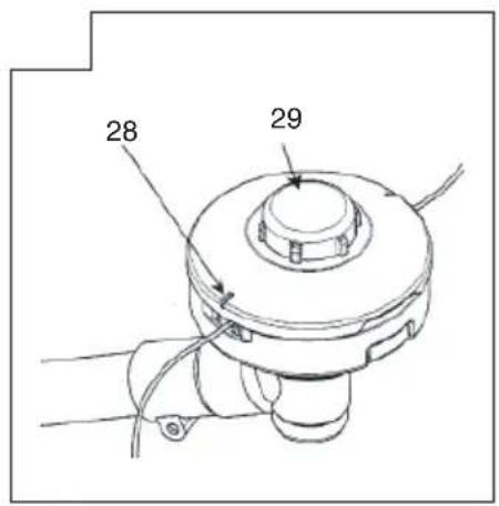

natural_image
Diagram of a mechanical tool with a curved arrow indicating motion or force direction (no text or symbols present)




natural_image
Line drawing of a hand operating a mechanical device with a black arrow pointing to the handle (no text or symbols present)
natural_image
Line drawing of a person wearing a helmet and safety harness (no text or symbols)

natural_image
Illustration of a person wearing a helmet and safety harness, holding a device with arrows indicating motion or force (no text or symbols present)


natural_image
Line drawing of a mechanical assembly with hands operating a tool (no text or symbols)

natural_image
Technical line drawing of a mechanical device with labeled component '41' (no text or symbols beyond label)


natural_image
Line drawing of a mechanical device with a lever and handle (no text or symbols)



MEANINGS OF SYMBOLS
NOTE: Some units do not carry them.
| SymbolsWARNINGThe following show symbols used for the machine. Be sure that you understand their meaning before use. | |||
 | Grass Trimmer / Brush Cutter Priming pump |  | |
 | It is important that you read, fully understand and observe the following safety precautions and warnings. Careless or improper use of the unit may cause serious or fatal injury. |  | Guaranteed sound power level |
 | Read, understand and follow all warnings and instructions in this manual and on the unit. |  | Blade thrust may occur when the spinning blade contacts a solid object in the critical area. A dangerous reaction may occur causing the entire unit and operator to be thrust violently. This reaction is called blade thrust. As a result, the operator may lose control of the unit which may cause serious or fatal injury. Blade thrust is more likely to occur in areas where it is difficult to see the material to be cut. |
 | Always wear eye, head and ear protectors when using this unit. | ||
| Do not use metal/rigid blades when this sign is shown on the unit. |  | Hot Surface - Contact with hot surface can cause serious burns. | |
 | Keep all children, bystandards and helpers 15 m away from the unit. If anyone approaches you, stop the engine and cutting attachment immediately. |  | The hedge trimmer attachment cannot be used on models with this label. |
 | Be careful of thrown objects. |  | Indicate handle location. Arrows which show limits for handle positioning. |
 | Shows maximum shaft speed. Do not use the cutting attachment whose max rpm is below the shaft rpm. |  | Displacement |
 | Gloves should be worn when necessary, e.g., when assembling cutting equipment. | Sweel | Spark plug |
| [0001] | Use anti-slip and sturdy footwear. |  Idle Idle | Idling speed |
| [0002] | Choke - Run position (Open) Speed of output shaft | SWEAL | |
| [0003] | Choke - Start position (Closed) | [TAWA] | Max. engine output |
| [0004] | On/Start Fuel tank capacity | Lowe | |
| [0005] | Off /Stop Dry weight | Sweel | |
 | Emergency stop Cutting attachment |  | |
| [0006] | Fuel and oil mixture | Sweel | Sound pressure level LpA by ISO 22868 Equivalent* |
| [0007] | Idle speed adjustment | SWEAL | Measured sound power level LwA by 2000/14/EC Racing |
| L_WA, Ra(G) 2000/14/EC | Guaranteed sound power level LwA by 2000/14/ECRacing | a_hv, eq(R) | Vibration level by ISO 22867Rear or Right handle / Equivalent* |
| a_hv, eq(F) | Vibration level by ISO 22867Front or Left handle / Equivalent* | K | Uncertainty |
| Before using your machineRead the manual carefully.Check that the cutting equipment is correctly assembled and adjusted.Start the unit and check the carburetor adjustment. See “MAINTENANCE”. | |||
NOTE: Equivalent noise level / vibration level are calculated as the time-weighted energy total for noise / vibration levels under various working conditions with the following time distribution:
* 1/2 Idle, 1/2 racing.
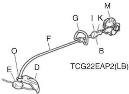
WHAT IS WHAT? (Fig. 1)
Since this manual covers several models, there may be some difference between pictures and your unit. Use the instructions that apply to your unit.
A: Fuel cap
B: Throttle trigger
C: Starter handle
D: Cutting attachment guard
E: Cutting attachment
F: Drive shaft tube
G: Handle
H: Hanger
I: Ignition switch
J: Harness (if so equipped)
K: Throttle trigger lockout
L: Choke lever
M: Engine
N: Gear case
O: Cutter case
P: Joint case
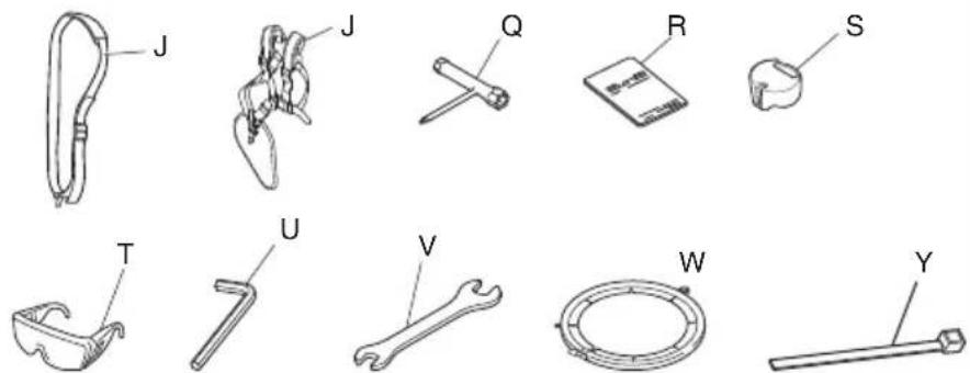
Q: Combi box spanner
R: Handling instructions
S: Swivel cap
T: Goggles
U: Hex bar wrench
V: Spanner (if so equipped)
W: Blade cover (if so equipped)
X: Muffl er cover
Y: Cord clump (if so equipped)
WARNINGS AND SAFETY INSTRUCTIONS
Pay special attention to statements preceded by the following words:
WARNING
Indicates a strong possibility of severe personal injury or loss of life, if instructions are not followed.
CAUTION
Indicates a possibility of personal injury or equipment damage, if instructions are not followed.
NOTE
Helpful information for correct function and use.
Operator safety
○ Wear head protection (1). (Fig. 2)
○ Always wear a safety face shield or goggles (2). (Fig. 2)
- Wear approved hearing protection (3). (Fig. 2)
Long-term exposure to noise can result in permanent hearing impairment.
Pay attention to your surroundings. Be aware of any bystanders who may be signaling a problem.
Remove safety equipment immediately upon shutting off engine.
○ Always wear heavy, long-sleeved shirts (4) and long pants (5) and non-slip boots (6) and gloves (7). (Fig. 2)
Do not wear loose clothing, jewelry, short pants, sandals or go barefoot.
Secure hair so it is above shoulder length.
○ Do not operate this tool when you are tired, ill or under the influence of alcohol, drugs or medication.
Do not operate the tool at night or under bad weather conditions when visibility is poor. And do not operate the tool when it is raining or right after it has been raining. Working on slippery ground could lead to an accident if you lose your balance.
Never let a child or inexperienced person operate the machine.
○ Do not start the engine if there are any flammables such as dry leaves, waste paper or fuel in the vicinity.
- Never start or run the engine inside a closed room or building. Breathing exhaust fumes can kill.
- Keep handles free of oil and fuel.
- Keep hands away from cutting equipment.
○ Do not grab or hold the unit by the cutting equipment.
- Gloves should be worn when installing or removing the cutting attachment. Failure to do so may result in injury.
When the unit is shut off, make sure the cutting attachment has stopped before the unit is set down.
When operation is prolonged, take a break periodically so that you may avoid possible Hand-Arm Vibration Syndrome (HAVS) which is caused by vibration.
WARNING
○ Always operate the tool with proper protective equipment and clothing. Failure to do so may result in accidents such as burns or injuries. (Fig. 2)
○ Do not touch the spark plug area or high voltage during operation. Doing so may result in electric shock.
○ Do not allow children near the tool during operation.
Do not touch the engine, muffler cover or exhaust vent during or shortly after operation. Doing so may result in burn or injury.
○ Antivibration systems do not guarantee that you will not sustain Hand-Arm Vibration Syndrome or carpal tunnel syndrome. Therefore, continual and regular users should monitor closely the condition of their hands and fingers. If any of the above symptoms appear, seek medical advice immediately.
If you are using any medical electric/electronic devices such as a pacemaker, consult your physician as well as the device manufacturer prior to operating any power equipment.
Unit/machine safety
○ Inspect the entire unit/machine before each use. Replace damaged parts. Check for fuel leaks and make sure all fasteners are in place and securely tightened.
○ Replace parts that are cracked, chipped or damaged in any way before using the unit/machine. Faulty parts may increase the risk of accidents and may lead to an injury.
○ Make sure the cutting attachment guard and harness are properly attached. Do not operate if cutting attachment guard and harness is not properly attached.
- Keep others away when making carburetor adjustments.
○ Use only accessories as recommended for this unit/machine by the manufacturer.
Before operation, make sure that there are no tools such as the adjustment key or spanner still attached to the unit.
WARNING
Never modify the unit/machine in any way. Do not use your unit/machine for any job except that for which it is intended.
○ Non-authorized modifications and/or accessories may result in serious personal injury or the death of the operator or others.
Fuel safety
○ Mix and pour fuel outdoors and where there are no sparks or flames.
○ Use a container approved for fuel.
○ Move at least 3 m away from fueling site before starting engine.
- Stop engine before removing fuel cap. Do not remove the fuel cap during operation.
○ Empty the fuel tank before storing the unit/machine. It is recommended that the fuel be emptied after each use. If fuel is left in the tank, store so fuel will not leak.
WARNING
○ Fuel is easy to ignite or get explosion or inhale fumes, so that pay special attention when handling or fi lling fuel.
○ Do not smoke or allow smoking near fuel or the unit/machine or while using the unit/machine.
○ Wipe up all fuel spills before starting engine.
○ Store unit/machine and fuel in area where fuel vapors cannot reach sparks or open flames from water heaters, electric motors or switches, furnaces. etc.
○ When using the unit in dry areas, make sure that fire extinguishing equipment is readily available.
☐ If you shut off the engine for refueling, make sure the unit has cooled down before adding fuel.
Cutting safety
○ Do not cut any material other than grass and brush.
○ Inspect the area to be cut before each use.
Remove objects which can be thrown or become entangled.
Do not operate in areas where there are tree roots or rocks.
☐ For respiratory protection, wear an aerosol protection mask when cutting the grass after insecticide is scattered.
Keep others including children, animals, bystanders and helpers outside the 15 m hazard zone. Stop the engine immediately if you are approached.
Please exercise caution as engine startup may be delayed after pulling the starter handle.
○ Always keep the engine on the right side of your body.
○ Hold the unit/machine firmly with both hands.
○ Keep firm footing and balance. Do not over-reach.
Losing your balance during work may lead to an injury.
Keep all parts of your body away from the muffler and cutting attachment when the engine is running.
○ Keep cutting attachment below knee level.
- Please exercise caution when operating in areas where electrical cables or gas pipes are present.
☐ Do not operate the cutting attachment for anything but clearing grass or bushes. Avoid operations where the cutting attachment may touch water such as puddles or dig into dirt. Failure to do so may result in injury or damage to the unit.
○ Avoid prolonged use at low speed range in which vibration is high. Doing so may result in engine damage.
When relocating to a new work area, or inspecting, adjusting or exchanging the unit's cutting attachments, accessories, etc., be sure to shut off the machine and ensure that all cutting attachments are stopped.
○ Never place the machine on the ground when running.
○ Never touch the cutting attachment when it is rotating.
○ Always ensure that the engine is shut off and any cutting attachments have completely stopped before clearing debris or removing grass from the cutting attachment.
○ Always carry a first-aid kit when operating any power equipment.
Turn off the engine and make sure the cutting attachment has come to a full stop before removing the unit from your body or before leaving the unit unattended.
○ If you accidentally bump or drop the unit, inspect it immediately to make sure there are no damage, cracks or deformations.
☐ If the tool is operating poorly and produces strange noise or vibrations, turn off the engine immediately and ask your dealer to have it inspected and repaired.
Continued use under these conditions could lead to injury or tool damage.
○ Use in accordance with local laws and regulations.
WARNING
KICKBACK DANGER (Fig. 3)
When using metal cutting attachments such as blades, contact with obstacles such as trees or other hard surfaces with the front or right portion of the spinning attachment may force the unit to catch on an obstacle, resulting in a kickback reaction towards the right side of the operator.
Kickback may occur when the cutting attachment comes into contact with tree stumps or rocks hidden behind weeds. Always make sure there are no obstacles hidden by weeds before starting work.
To minimize the danger of kickbacks when they do occur, always position the unit to the right side of the body during operation. With the operator properly positioned as the cutting attachment rotates, this will reduce the danger of the unit's direct contact with the body.
Maintenance safety
○ Maintain the unit/machine according to recommended procedures.
○ Disconnect the spark plug before performing maintenance except for carburetor adjustments.
○ Keep others away when making carburetor adjustments.
○ Use only genuine Tanaka replacement parts as recommended by the manufacturer.
CAUTION
Do not disassemble the recoil starter. There is a possibility of personal injury with recoil spring.
WARNING
Improper maintenance could result in serious engine damage or in serious personal injury.
Transport and storage
○ Carry the unit/machine by hand with the engine stopped and the muffler away from your body.
○ Allow the engine to cool, empty the fuel tank, and secure the unit/machine before storing or transporting. Failure to do so may result in fire or accidents.
○ Empty the fuel tank before storing the unit/machine. It is recommended that the fuel be emptied after each use. If fuel is left in the tank, store so fuel will not leak.
○ Store unit/machine out of the reach of children.
○ Clean and maintain the unit carefully and store it in a dry place.
○ Make sure engine switch is off when transporting or storing.
When transporting and storing, either remove the cutting attachment or place the blade cover over the blade.
English
- You have to secure the machine during transport to prevent loss of fuel, damage or injury.
○ If a warning label cannot be read, peels off or becomes indistinct, replace it with a new one. To purchase new labels, contact Tanaka dealer.
If situations occur which are not covered in this manual, take care and use common sense. Contact Tanaka dealer if you need assistance.
SPECIFICATIONS
The SPECIFICATIONS of this machine are listed in the table on page 242, 243.
NOTE
All data subject to change without notice.
ASSEMBLY PROCEDURES
Drive shaft to engine (Fig. 4)
Loosen tube locking bolt (8) about ten turns so that the bolt point will not obstruct drive shaft tube to be inserted. When inserting drive shaft tube, hold the tube locking bolt outward preventing inside fi tting from obstructing as well.
Insert the drive shaft into the clutch case of the engine properly until the marked position (9) on the drive shaft tube meets the clutch case.
Some models may come with the drive shaft already installed.
NOTE
When it is hard to insert drive shaft up to the marked position on the drive shaft tube, turn drive shaft by the cutter mounting end clockwise or counter-clockwise. Tighten tube locking bolt lining up the hole in the shaft tube. Then tighten clamp bolt securely.
Installation of attachment (TCG22EAP2 (SLD) only)
- Join the attachment in place of it.
- Make sure the lock pin (10) fits in the location hole (11) of tube and that the tube will not come off. (Fig. 5)
- Tighten the knob nut (12) securely. (Fig. 5)
CAUTION
When you pull and release the lock pin (10), always make sure it returns to its original position.
○ Always check the label to see if an attachment can be used with a unit.
Installation of handle
(1) Loop handle type (Fig. 6)
Attach the handle to the drive shaft tube with the angle towards the engine.
Adjust the location to the most comfortable position before operation.
Make sure to securely attach the handle with the 2 bolts.
NOTE
If your unit has handle location label (13) on drive shaft tube, follow the illustration.
WARNING
Do not use metal or plastic blade cutting attachments with loop handle type.
(2) Bike handle type (Fig. 7)
Remove the handle bracket (14) from the assembly.
Place the handles and attach the handle bracket with four bolts lightly. Adjust to appropriate position. Then attach it firmly with the bolts.
Attach the protection tube to the drive shaft tube or handle using cord clamps (15) to make sure there is no slack. (Fig. 8)
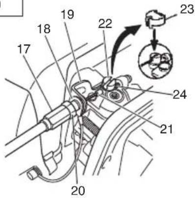
Installation of throttle wire / stop cord
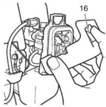
Press the upper tab (16) and open the air cleaner cover. (Fig. 9)
Connect stop cords. (Fig. 10)
If the throttle outer end (17) is threaded on your unit, screw it and the earth terminal (18) (if so equipped) into the cable adjuster stay (19) all the way, and then tighten this cable end using the adjuster nut (20) against the cable adjuster stay (19).
Connect throttle wire end (21) to swivel (22) of carburetor and install swivel cap (23) (if so equipped) where is included in tool bag, onto swivel (22). (Fig. 11)
Some models may come with the parts installed.
CAUTION
Open and close the throttle and verify that the swivel (22) abuts against screw (24) when the throttle is closed.
Installation of harness
(If so equipped)
WARNING
If the product includes a harness, always make sure to use it.
Attach the harness hook (25) to the hanger (26) on the drive shaft tube. (Fig. 12)
Adjust the length of the harness for easy operation of the tool.
NOTE
You may need to adjust the position of the hangar (26) to balance the unit. To do so, loosen bolt (27) and adjust the position of hangar (26). After adjusting as necessary, make sure to securely tighten the bolt (27). (Fig. 12)
Installation of cutting attachment guard
WARNING
If an incorrect or faulty guard is fitted, this may cause serious personal injury.
CAUTION
Some cutting attachment guards are equipped with sharp line limiters. Be careful with handling it.
NOTE
When using a trimmer head with two piece type cutting attachment guard, attach the guard extension to the cutting attachment guard. (Fig. 13)
○ The guard bracket may come already mounted to the gear case on some models.
Align the cutting attachment guard with the guard bracket and secure it to the drive shaft tube, using the bolt and cover bracket. (Fig. 14)
WARNING
Remove the guard extension when using metal or plastic blades. Failure to do so may result in injury or damage to the cutting attachment guard.
NOTE
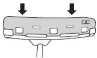
To remove the guard extension, refer to the drawings. Wear gloves as the extension has a sharp line limiter, then push the three square tabs on the guard one by one in order. (Fig. 15)
(Curved shaft model)
Insert the cutter case between the guard bracket and cutting attachment guard, and secure it with the bolt. (Fig. 16)
Installation of cutting attachment
WARNING
○ Install the cutting attachment properly and securely as instructed in the handling instructions. If not attached properly or securely, it may come off and cause serious and/or fatal injury.
○ Do not install or remove cutting attachments while the engine is running.
○ Always use genuine Tanaka cutting attachments and metal fittings.
Installation of semi-auto cutting head
1. Function
Automatically feeds more nylon cutting line when it is tapped at low rpm (not greater than 4500 min ^-1 ).
Specifications
| Code No. | Typ of attaching screw | Direction of rotation | Size of attaching screw |
| 6696454 | Female screw | Counter-clockwise | M10xP1.25-LH |
| 6696597 | Female screw C | lockwise M8xP1 | .25-LH |
Applicable nylon cord
Cord diameter: 3.0 mm Length: 2 m
Cord diameter: 2.4 mm Length: 4 m
2. Precautions
○ The case must be securely attached to the cover.
○ Check the cover, case and other components for cracks or other damage.
○ Check the case and button for wear.
If the wear limit mark (28) on the case is no longer visible or there is a hole in the bottom (29) of the button, change the new parts immediately. (Fig. 17)
- The cutting head must be securely mounted to the unit's gear case/cutter case.
☐ If the cutting head does not feed cutting line properly, check that the nylon line and all components are properly installed. Contact Tanaka dealer if you need assistance.
WARNING
For Tanaka heads, use only fl exible, non-metallic line recommended by the manufacturer. Never use wire or wire ropes. They can break off and become a dangerous projectile.
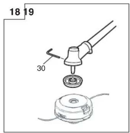
3. Installation (Fig. 18)
Insert the allen wrench (30) into the hole of the gear case/cutter case in order to lock the drive shaft tube. Install cutting head on gear case/cutter case of grass trimmers/brush cutters. The mounting nut is left-hand-threaded. Turn clockwise to loosen/counter-clockwise to tighten.
NOTE
☐ For curved drive shaft tube models, the mounting nut is right-hand-threaded. Turn counter-clockwise to loosen/clockwise to tighten.
○ Since the cutter holder cap is not used here, keep it for when a metal blade is used, if so equipped.
4. Adjusting line length
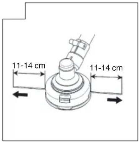
Set the engine speed as low as possible and tap the head on the ground. The nylon line will be drawn out about 3 cm with each tap. (Fig. 19) Also, you can extend the nylon line by hand but the engine must be completely stopped. (Fig. 20) Adjust the nylon line to the proper length of 11–14 cm before each operation.
Installation of cutting blade (Fig. 21)
(If so equipped)
Insert the alien wrench (30) into the hole of the gear case in order to lock the shaft.
Assemble in the following order: Cutter holder (A) (31), blade (32), cutter holder (B) (33), nut cover (34).
Tighten the fixing nut with the box wrench. Please note that the cutter fixing nut (35) has left-handed threads (clockwise to loosen/ counter-clockwise to tighten).
NOTE
○ When installing cutter holder (B) (33), be sure to set concave side upward.
○ When installing or removing a blade, make sure to wear gloves and place the blade cover over the blade.
CAUTION
Check a nut cover (34) for wear or cracks before operation. If any damage or wear is found, replace it, as it is an article of consumption.
WARNING
When installing a cutting blade, make sure that there are no cracks or any damage in it and that the cutting edges are facing the correct direction.
○ Remove any surface grit from blade installation fittings (cutter holder (A) (31), cutter holder (B) (33), nut cover (34), nut (35)). Failure to do so may result in the loosening of nuts.
☐ The protrusion of the cutter holder (A) (31) may become misaligned with the blade (32) while tightening nut (35). Before operation, make sure the blade has been properly installed. (Fig. 22)
○ Rotate the blade by hand and make sure there is no rocking or abnormal noise. Rocking may cause abnormal vibrations or result in the loosening of nuts.
OPERATING PROCEDURES
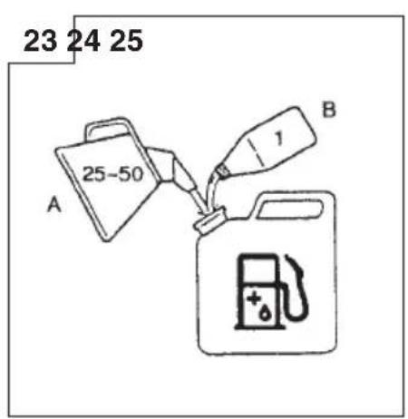
Fuel (Fig. 23)
WARNING
○ The trimmer is equipped with a two-stroke engine. Always run the engine on fuel, which is mixed with oil.
Provide good ventilation, when fueling or handling fuel.
- Fuel is highly flammable and it is possible to get seriously injured when inhaling or spilling on your body.
Always pay attention when handling fuel. Always have good ventilation when handling fuel inside building.
Fuel
○ Always use branded 89 octane unleaded gasoline.
○ Use genuine two-cycle oil or use a mix between 25:1 to 50:1, please consult about the mixture ratio to Tanaka dealer.
○ If genuine oil is not available, use an anti-oxidant added quality oil expressly labeled for air-cooled 2-cycle engine use (JASO FC GRADE OIL or ISO EGC GRADE). Do not use BIA or TCW (2-stroke water-cooling type) mixed oil.
○ Never use multi-grade oil (10 W/30) or waste oil.
- Never mix fuel and oil in machine's fuel tank. Always mix fuel and oil in a separate clean container.
Always start by filling half the amount of gasoline, which is to be used.
Then add the whole amount of oil. Mix (shake) the fuel mixture. Add the remaining amount of gasoline.
Mix (shake) the fuel-mix thoroughly before filling the fuel tank.
Mixing amount of two-cycle oil and gasoline
| Gasoline (Liter) | Two-cycle oil (ml) | |
| Ratio 50:1 | Ratio 25:1 | |
| 0.5 | 10 —— | 20 |
| 1 | 20 —— | 40 |
| 2 | 40 —— | 80 |
| 4 | 80 —— | 160 |
English
Fueling
WARNING
○ Always shut off the engine and let it cool for a few minutes before refueling.
Do not smoke or bring flames or sparks near the fueling site.
- Slowly open the fuel tank, when filling up with fuel, so that possible over-pressure disappears.
○ Tighten the fuel tank cap carefully, after fueling.
○ Always move the unit at least 3 m from the fueling area before starting.
○ Always wash any spilled fuel from clothing immediately with soap.
○ Be sure to check any fuel leakage after refueling.
Before fueling, in order to remove static electricity from the main body, the fuel container and the operator, please touch the ground that is slightly damp.
Before fueling, clean the tank cap area carefully, to ensure that no dirt falls into the tank. Make sure that the fuel is well mixed by shaking the container, before fueling.
Starting
CAUTION
Before starting, make sure the cutting attachment does not touch anything.
(1) Starting the cold engine
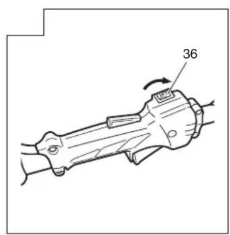
1. Set ignition switch (36) to ON position. (Fig. 24)
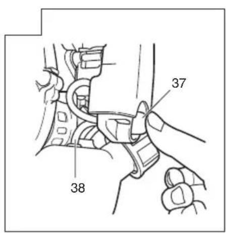
2. Push priming bulb (37) several times so that fuel flows through return pipe (38). (Fig. 25)
3. Set choke lever (39) to START position (closed) (A). (Fig. 26)
4. Pull recoil starter briskly, taking care to keep the handle in your grasp and not allowing it to snap back. (Fig. 27)
5. When you hear the engine want to start, return choke lever to RUN position (open) (B). (Fig. 26)
6. Pull recoil starter briskly again. (Fig. 27)
NOTE
If engine does not start, repeat procedures from 2 to 5.
- Then allow the engine about 2–3 minutes to warm up before subjecting it to any load.
- Check that the cutting attachment does not rotate when the engine is idling.
(2) Starting the warm engine
Use only 1, 6 and 8 of the starting procedure for a cold engine.
If the engine does not start, use the same starting procedure as for a cold engine.
Cutting
WARNING
○ Always use the harness (if so equipped) and wear the proper attire and protective equipment when operating the unit. (Fig. 28)
Keep others including children, animals, bystanders and helpers outside the 15 m hazard zone. Stop the engine immediately if you are approached. (Fig. 29)
When grass or vines wrap around attachment, stop engine and attachment and remove them. Continuing operation with grass or vines wrapped around the attachment may result in damages such as early abrasion of the clutch.
CAUTION
Use and points of caution will vary depending on the type of cutting attachment. For safe use, make sure to follow the instructions and guidelines provided with each type.
NOTE
○ Press the quick release button or pull emergency release flap (If so equipped) in the event of emergency. (Fig. 30)
○ Use in accordance with local laws and regulations.
(1) Using a semi-auto cutting head
Set the engine at high speed when using this attachment.
○ Cut grass from left to right. The cut grass will be discharged away from the body, minimizing transfer to your clothes. (Fig. 31)
○ Cut grass from left to right. The cut grass will be discharged away from the body, minimizing transfer to your clothes. (Fig. 31)
○ Cut grass from right to left as the cutting attachment of the curved drive shaft tube model rotates clockwise.
With nylon cord, use about 2 cm of the end of the cord to cut grass. Using the full length of the cord will reduce rotation speed and make cutting difficult.
NOTE
Automatically feeds more nylon cutting line when it is tapped at low rpm (not greater than 4500 min ^-1 ).
WARNING
☐ This product is equipped with a line limiter that will automatically cut any excess cord. When operating the unit, do not remove the guard or line limiter.
As the resistance is greater for nylon cords as opposed to blades, mishandling could increase engine load and result in damage.
☐ Do not use with the engine set at low speeds. If the engine speed is low, grass may wrap around the attachment, causing the clutch to slip which could result in clutch abrasion.
With nylon cord cutters, always use over 15 cm of cord. If the length of the cord is too short, rotation speed will increase and may cause damage to the nylon cord cutter. As the curved drive shaft tube model in particular is not equipped with a deceleration mechanism, the possibility of increased rotation speed for the cutting attachment is high.
(2) Using a blade
○ Adjust engine speed according to the resistance of the grass. For soft grass, use low speeds, For tough clumps of grass, use high speeds.
○ Cut grass from right to left, using the left side of the blade to cut. (Fig. 32)
○ Slightly tilting the blade to the left while cutting will pile the cut grass to the left, making collection easy.
NOTE
Excessively increasing rotation speed may cause increased blade wear, vibration and noise. It will also result in increased fuel consumption.
WARNING
○ Blade thrust may occur when the spinning blade contacts a solid object in the critical area.
A dangerous reaction may occur causing the entire unit and operator to be thrust violently. This reaction is called blade thrust. As a result, the operator may lose control of the unit which may cause serious or fatal injury. Blade thrust is more likely to occur in areas where it is difficult to see the material to be cut.
☐ If cutting attachment should strike against stones or other debris, stop the engine and make sure that the attachment and related parts are undamaged.
Stopping (Fig. 33)
Decrease engine speed and run at an idle for a few minutes, then turn off ignition switch (36).
WARNING
A cutting attachment can injure while it continues to spin after the engine is stopped or power control is released. When the unit is turned off, make sure the cutting attachment has stopped before the unit is set down.
MAINTENANCE
MAINTENANCE, REPLACEMENT OR REPAIR OF THE EMISSION CONTROL DEVICES AND SYSTEMS MAY BE PERFORMED BY ANY NON-ROAD ENGINE REPAIR ESTABLISHMENT OR INDIVIDUAL.
Carburetor adjustment (Fig. 34)

WARNING
☐ The cutting attachment may be spinning during carburetor adjustments.
Never start the engine without the complete clutch cover and tube assembled! Otherwise the clutch can come loose and cause personal injuries.
In the carburetor, fuel is mixed with air. When the engine is test run at the factory, the carburetor is adjusted. A further adjustment may be required, according to climate and altitude. The carburetor has one adjustment possibility:
T = Idle speed adjustment screw.
Idle speed adjustment (T)
Check that the air filter is clean. When the idle speed is correct, the cutting attachment will not rotate. If adjustment is required, close (clockwise) the T-screw, with the engine running, until the cutting attachment starts to rotate. Open (counter-clockwise) the screw until the cutting attachment stops. You have reached the correct idle speed when the engine runs smoothly in all positions well below the rpm when the cutting attachment starts to rotate.
If the cutting attachment still rotates after idle speed adjustment, contact Tanaka dealer.
NOTE
Standard Idle rpm is 2800 - 3200 min ^-1 .

WARNING
When the engine is idling the cutting attachment must under no circumstances rotate.
Air fi Iter (Fig. 35)
The air filter (40) must be cleaned from dust and dirt in order to avoid:
○ Carburetor malfunctions.
○ Starting problems.
○ Engine power reduction.
○ Unnecessary wear on the engine parts.
○ Abnormal fuel consumption.
Clean the air filter daily or more often if working in exceptionally dusty areas.
Open the air filter cover and remove the air filter (40). Rinse it in warm soap suds.
Check that the fi iter is dry before reassembly.
An air filter that has been used for some time cannot be cleaned completely. Therefore, it must regularly be replaced with a new one. A damaged filter must always be replaced.
Fuel fi Iter (Fig. 36)
Check the fuel filter occasionally for clogging as insufficient fuel flow could affect engine speed.
Drain all fuel from fuel tank and pull fuel filter (41) from tank. Rinse it in warm water with detergent.
Rinse thoroughly until all traces of detergent are eliminated. Squeeze, away excess water and allow element to air dry.
NOTE
If the fuel filter (41) is hard due to excessive dirt buildup, replace it.
Spark plug (Fig. 37)
The spark plug condition is influenced by:
○ An incorrect carburetor setting.
○ Wrong fuel mixture (too much oil in the gasoline)
○ A dirty air fi Iter.
○ Hard running conditions (such as cold weather).
These factors cause deposits on the spark plug electrodes, which may result in malfunction and starting difficulties. If the engine is low on power, difficult to start or runs poorly at idling speed, always check the spark plug first.
If the spark plug is dirty, clean it and check the electrode gap. Re-adjust if necessary. The correct gap is 0.6 mm. The spark plug should be replaced after about 100 operation hours or earlier if the electrodes are badly eroded.
NOTE
In some areas, local law requires using a resistor spark plug to suppress ignition signals. If this machine was originally equipped with resistor spark plug, use same type of spark plug for replacement.
Flexible drive shaft (Fig. 38)
(curved drive shaft tube model)
Flexible drive shaft should be removed and lubricated with good quality lithium grease every 20 hours. To remove the flexible shaft, first remove screw (42), loosen bolt (43) and remove the cutter case then pull the shaft out of the drive shaft tube. Clean the shaft off and apply a generous coat of lithium grease to it and insert if back into the drive shaft tube, turn it unit it drops into place then install the cutter case, install & tighten screw (42) and bolt (43).
Gear case (Fig. 39)
Check gear case or angle gear for grease level about every 50 hours of operation by removing the grease filler plug on the side of gear case.
If no grease can be seen on the flanks of the gears, fill the gear case with quality lithium based multipurpose grease up to 3/4. Do not completely fill the gear case.
CAUTION
○ Make sure to remove any dirt or grit when attaching the plug to its original position.
Before attempting inspection or maintenance of the gear case, make sure the case has cooled.
Semi-auto cutting head
Nylon line replacement
- Remove the case (44) by firmly pushing inward the locking tabs with your thumbs as shown in Fig. 40.
- After removing the case, take out the reel and discard the remaining line.
- Fold the new nylon line unevenly in half as shown in picture.
Hook the U-shaped end of the nylon line into the groove (45) on the center partition of the reel.
Wind both halves of the line on the reel in the same direction, keeping each half of the line on its own side of the partition. (Fig. 41)
- Push each line into the stopper holes (46), leaving the loose ends approx. 10 cm in length. (Fig. 42)
- Insert both loose ends of the line through the cord guide (47) when placing the reel in the case. (Fig. 43)
NOTE
When placing a reel in the case, try to line up the stopper holes (46) with the cord guide (47) for easier line release later.
- Place the cover over the case so that the cap locking tabs (48) on the case meet the long holes (49) on the cover. Then push the case securely until it clicks into place. (Fig. 44)
- The initial cutting line length should be approx. 11–14 cm and should be equal on both sides. (Fig. 45)
Blade (Fig. 46)
WARNING
Wear protective gloves when handling or performing maintenance on the blade.
○ Use a sharp blade. A dull blade is more likely to snag and thrust.
Replace the fastening nut if it is damaged and hard to tighten.
When replacing blade, purchase one recommended by Tanaka, with a 25.4 mm (one inch) ft tting hole.
English
○ In the case of a 3 or 4 tooth blade (50), it can be used on either side.
○ Use the correct blade for the type of work.
○ When replacing blades, use appropriate tools.
☐ When cutting edges become dull, re-sharpen or file as shown in the illustration. Incorrect sharpening may cause excessive vibration.
- Discard blades that are bent, warped, cracked, broken or damaged in any way.
NOTE
When sharpening blade it is important to maintain an original shape of radius at the base of the tooth to avoid cracking.
For long-term storage
Drain all fuel from the fuel tank. Start and let engine run until it stops. Repair any damage which has resulted from use. Clean the unit with a clean rag, or the use of high pressure air hose. Put a few drops of two-cycle engine oil into the cylinder through the spark plug hole, and spin the engine over several times to distribute oil.
Cover the unit and store it in a dry area.
Maintenance schedule
Below you will find some general maintenance instructions. For further information please contact Tanaka dealer.
Daily maintenance
○ Clean the exterior of the unit.
○ Check that the harness is undamaged.
○ Check the cutting attachment guard for damage or cracks. Change the guard in case of impacts or cracks.
☐ Check that the cutting attachment is properly centered, sharp, and without cracks. An off-center cutting attachment induces heavy vibrations that may damage the unit.
○ Check that the cutting attachment nut is sufficiently tightened.
○ Make sure that the blade cover is undamaged and that it can be securely fitted.
○ Check that nuts and screws are sufficiently tightened.
○ Check that the unit is undamaged and free of defects.
Weekly maintenance
○ Check the starter, especially the cord and return spring.
○ Clean the exterior of the spark plug.
○ Remove the spark plug and check the electrode gap. Adjust it to 0.6 mm, or change the spark plug.
○ Check that the angle gear is filled with grease up to 3/4.
○ Clean the air filter.
Monthly maintenance
○ Rinse the fuel tank with gasoline.
○ Clean the exterior of the carburetor and the space around it.
○ Clean the fan and the space around it.
SELECTING ACCESSORIES
The accessories of this machine are listed on page 244.
SELECTING CUTTING ATTACHMENTS
Recommended accessories for each model are presented in the table below.
For purchases, contact Tanaka dealer.
Please check carefully as those accessories not marked with "●" cannot be attached.
List of recommended accessories
| Type Name | Specifi cation LOOP HANDLE | MULTI PURPOSE | ||||||||||
| Diameter | Feed System Adapter or No. of Teeth (Blade) | Blade Thickness (mm) or Trimmer line Diameter (mm) | TCG22EAP2 (LB) | TCG22EAP2 (SL) | TCG24EAP2 (SL) | TCG27EAP2 (SL) | TCG22EAP2 (S) | TCG24EAP2 (S) | TCG27EAP2 (S) | TCG22EAP2 (SLD) | ||
| ALUMINUM HEADS | NYLON HEAD CH-100 (W/NYLON LINE) | 4" | Pre-Cut Line | 2.2 - 3.0 | ● | ● | ● | ● | ● | ● | ● | ● |
| NYLON HEAD CH-100 | ● | ● | ● | ● | ● | ● | ● | ● | ||||
| NYLON HEAD CH-300 (W/CUTTER HOLDER CAP) | 5" | Manual line feed | 2.2 - 2.7 | ● | ● | |||||||
| NYLON HEAD CH-300 | ● | ● | ||||||||||
| TAP & GO NYLON HEADS | NYLON HEAD BF-4 | 4" | R M8 x 1.25 Nut | 2.2 - 3.0 | ● | |||||||
| NYLON HEAD BF-5 | 5" | L M10 x 1.25 Nut L M8 x 1.25 Nut | 2.2 - 3.0 | ● | ● | ● | ● | ● | ● | ● | ||
| BLADES | BLADE B3/10/2.0 | 10" 3 2.0 | ● | ● | ||||||||
| BLADE B3/12/3.0 | 12" 3 3.0 | ● | ||||||||||
| BLADE B4/9/1.6 | 9" 4 1.6 | ● | ● | ● | ||||||||
| BLADE B4/10/1.6 | 10" 4 1.6 | ● | ● | ● | ||||||||
TROUBLESHOOTING
Use the inspections in the table below if the tool does not operate normally. If this does not remedy the problem, consult your dealer or the Tanaka dealer.
| Condition Cause Remedy | |||
| Engine does not start | Fuel system | Fuel tank is empty or fuel level is low | Fill the fuel tank with the correct fuel mix (25:1-50:1) |
| Fuel tank contains old fuel (off ensive odor) | Replace with new fuel | ||
| Too much fuel is absorbed and spark plug is wet | 1. Disconnect the spark plug and allow to dry2. Pull the starter handle 5 or 6 times to remove the surplus fuel3. Attach the spark plug4. Set the choke lever to RUN position and pull the starter handle | ||
| Fuel filter is clogged with dirt | Clean the fuel filter | ||
| Fuel pipe is bent or disconnected | Ensure that the fuel flows smoothly | ||
| Carburetor malfunction Contact Tanaka dealer | |||
| Electrical system | Stop switch lead has short-circuited Contact Tanaka dealer | ||
| Spark plug is dirty Replace or clean the spark plug | |||
| Electrode gap is too big Adjust the gap to 0.6mm | |||
| Poor connection between high tension cable and spark plug | Reconnect | ||
| Electrical system malfunction Contact Tanaka dealer | |||
| Other | Muffler exhaust port is clogged with carbon | Contact Tanaka dealer for repair | |
| Engine starts but cuts out straightawayEngine is apt to cut out | Fuel system | Fuel tank is empty or fuel level is low | Fill the fuel tank with the correct fuel mix (25:1-50:1) |
| Fuel tank contains old fuel (off ensive odor) | Replace with new fuel | ||
| Two-cycle oil has not been added Contact Tanaka dealer | |||
| Choke lever is in START position Set the choke lever to RUN position | |||
| Air has got into fuel system Reconnect the fuel pipe or joint | |||
| Carburetor malfunction Contact Tanaka dealer | |||
| Electrical system | Ignition failure | ||
| Spark plug failure Replace with new spark plug | |||
| Electrical system failure | Contact Tanaka dealer | ||
| Other | Engine overheating | ||
| Wrong spark plug model | Replace with designated part See “SPECIFICATIONS” | ||
| Dirty air cleaner | Clean | ||
| Carbon clogging (muffler exhaust port) | Clean | ||
| Insuffi cient compression (piston, piston ring, cylinder) | Contact Tanaka dealer | ||
| Abnormal vibration | Cutting attachment is not properly installed | See “Installation of cutting attachment” | |
| Handle, handle bracket or other fastening part is loose | Check and tighten | ||
| Blade is bent or damaged | Replace with new blade | ||
| Grass is wrapped round gear case | Remove grass | ||
| Engine is running but blade does not move Movement is poor | Grass is wrapped round gear case | Remove grass and dirt | |
| Engine does not stop Stop switch | failure | Set the choke lever to START position to stop the engineCease use immediately and contact Tanaka dealer | |
| Engine stops when throttle is closed | Idle speed is too low Contact Tanaka dealer | ||
| Blade continues rotating when throttle is closed | Idle speed is too highThrottle wire is too taut | Contact Tanaka dealer | |
SYMBOLBEDEUTUNGEN
Cordon de nylon applicable
WAARSCHUWINGEN EN VEILIGHEIDSINSTRUCTIES
Diametru coardă: Φ3,0 mm Lungime: 2 m
Diametru coardă: Φ2,4 mm Lungime: 4 m
2. Precauții
UPOZORENJA I BEZBEDNOSNA UPUTSTVA
UPOZORENJA I SIGURNOSNE UPUTE
Posebno obratite pažnju na izjave kojima prethode sljedeće riječi:
⚠ UPOZORENJE
natural_image
Simple line drawing of a circular mechanical component with no text or symbols

natural_image
Simple line drawing of a circular mechanical component with two curved wires, no text or symbols present.
natural_image
Line drawing of a quill pen in an inkwell (no text or symbols)| English NederlandsObject of declaration: Tanaka Grass Trimmer / Brush Cutter TCG 22EAP2 (SL) / TCG 22EAP2 (S) /TCG 22EAP2 (SLD) / TCG 22EAP2 (LB) / TCG 24EAP2 (SL) / TCG 24EAP2 (S) /TCG 27EAP2 (SL) / TCG 27EAP2 (S)EC DECLARATION OF CONFORMITY(Applies to Europe only)We declare under our sole responsibility that this product is in conformity with directives 2006/42/EC, 2004/108/EC and 2000/14/EC. The following standards have been taken into consideration.EN ISO 11806 : 2011Annex V (2000/14/EC): For information relating to noise emissions, see the chapter specifi cations.The European Standards Manager at Hitachi Koki Europe Ltd. is authorized to compile the technical fi le.This declaration is applicable to the product affi xed CE marking. | Onderwerp van verklaring: Tanaka Motor Zeis / Motor Bosmaaier TCG 22EAP2 (SL) / TCG 22EAP2 (S) /TCG 22EAP2 (SLD) / TCG 22EAP2 (LB) / TCG 24EAP2 (SL) /TCG 24EAP2 (S) / TCG 27EAP2 (SL) / TCG 27EAP2 (S)EC VERKLARING VAN CONFORMITEIT(Geldt alleen voor Europa)Wij verklaren onder eigen verantwoordelijkheid dat dit product voldoet aan de richtlijnen 2006/42/EC, 2004/108/EC en 2000/14/EC. De volgende standaards zijn toegepast.EN ISO 11806 : 2011Aanvulling V (2000/14/EC): Voor informatie over de lawaai-emissie wordt u verwezen naar het hoofdstuk met de specifi caties.De manager voor Europese normen van Hitachi Koki Europe Ltd. heeft de bevoegdheid tot het samenstellen van het technische bestand.Deze verklaring is van toepassing op produkten voorzien van de CE-markeringen. | |
| Deutsch Español | ||
| Gegenstand der Erklärung: Tanaka Rasentrimmer / Motorsense TCG 22EAP2 (SL) / TCG 22EAP2 (S) /TCG 22EAP2 (SLD) / TCG 22EAP2 (LB) / TCG 24EAP2 (SL) /TCG 24EAP2 (S) / TCG 27EAP2 (SL) / TCG 27EAP2 (S)ERKLÄRUNG ZUR KONFORMITÄT MIT EG-REGELN(Gilt nur für Europa)Wir erklären eigenverantwortlich, dass dieses Produkt den Richtlinien 2006/42/EG, 2004/108/EG und 2000/14/EG entspricht. Folgende Standards wurden berücksichtigt.EN ISO 11806 : 2011Anhang V (2000/14/EG): Informationen zur Geräuschentwicklung finden Sie im Kapitel Spezifizierungen.Der Manager für europäische Standards bei der Hitachi Koki Europe Ltd. ist zum Verfassen der technischen Datei befugt.Diese Erklärung gilt für Produkte, die die CE-Markierung tragen. | Objeto de declaración: Tanaka Motoguadañas / Desbrozadoras TCG 22EAP2 (SL) / TCG 22EAP2 (S) /TCG 22EAP2 (SLD) / TCG 22EAP2 (LB) / TCG 24EAP2 (SL) / TCG 24EAP2 (S) /TCG 27EAP2 (SL) / TCG 27EAP2 (S)DECLARACIÓN DE CONFORMIDAD DE LA CE(De aplicación sólo en Europa)Declaramos bajo nuestra exclusiva responsabilidad que este producto es conforme a las directivas 2006/42/CE, 2004/108/CE y 2000/14/CE. Se han tenido en consideración las siguientes normas.EN ISO 11806 : 2011Anexo V (2000/14/CE): Para más información sobre la emisión de ruidos, consulte la sección de especificaciones.El Jefe de Normas Europeas de Hitachi Koki Europe Ltd. está autorizado para recopilar archivos técnicos.Esta declaración se aplica a los productos con marcas de la CE. | |
| Français Português | ||
| Objet de la déclaration: Tanaka Coupe-Herbes / Débroussailleuse TCG 22EAP2 (SL) / TCG 22EAP2 (S) /TCG 22EAP2 (SLD) / TCG 22EAP2 (LB) / TCG 24EAP2 (SL) / TCG 24EAP2 (S) /TCG 27EAP2 (SL) / TCG 27EAP2 (S)DECLARATION DE CONFORMITE EC(Concerne l'Europe uniquement)Nous déclarons sur la foi de notre seule responsabilité que ce produit est conforme aux dispositions des directives 2006/42/EC, 2004/108/EC et 2000/14/EC. Les normes suivantes ont été prises en considération.EN ISO 11806 : 2011Annexe V (2000/14/EC): Pour les informations relatives aux émissions de bruits, reportez-vous au chapitre Caractéristiques.Le responsable des normes européennes d'Hitachi Koki Europe Ltd. est autorisé à compiler les données techniques.Cette déclaration s'applique aux produits désignés CE. | Objeto de declaración: Tanaka Foice a motor / Roçadora TCG 22EAP2 (SL) / TCG 22EAP2 (S) /TCG 22EAP2 (SLD) / TCG 22EAP2 (LB) / TCG 24EAP2 (SL) /TCG 24EAP2 (S) / TCG 27EAP2 (SL) / TCG 27EAP2 (S)DECLARAÇÃO DE CONFORMIDADE CE(Aplica-se apenas à Europa)Declaramos, sob nossa única responsabilidade, que este produto está em conformidade com as directivas 2006/42/CE, 2004/108/CE e 2000/14/CE. As normas seguintes foram tomadas em consideração. EN ISO 11806 : 2011Anexo V (2000/14/CE): Para obter mais informações relacionadas com emissões de ruído, consulte as especificações do capítulo.O Gestor de Normas Europeias da Hitachi Koki Europe Ltd. está autorizado a compilar o fi cheiro técnico.Esta declaración se aplica aos produtos designados CE. | |
| Italiano Ελλήνικά | ||
| Oggetto della dichiarazione: Tanaka Bordatore / Decespugliatore TCG 22EAP2 (SL) / TCG 22EAP2 (S) /TCG 22EAP2 (SLD) / TCG 22EAP2 (LB) / TCG 24EAP2 (SL) /TCG 24EAP2 (S) / TCG 27EAP2 (SL) / TCG 27EAP2 (S)DICHIARAZIONE DI CONFORMITÀ CE(Si applica solo all'Europa)Dichiariamo sotto la nostra esclusiva responsabilità che questo prodotto è conforme alle direttive 2006/42/CE, 2004/108/CE e 2000/14/CE. Sono stati presi in considerazione i seguenti standard.EN ISO 11806 : 2011Allegato V (2000/14/CE): Per informazioni riguardo alle emissioni di rumore, consultare le specifi che del capitolo.Il Responsabile delle Norme Europee di Hitachi Koki Ltd. è autorizzato a compilare la scheda tecnica.Questa dichiarazione è applicabile ai prodotti cui sono applicati i marchi CE. | Αντικείμενο δήλωσης: Tanaka Χλοοκοπτικό / Θαμνοκοπτικό TCG 22EAP2 (SL) / TCG 22EAP2 (S) /TCG 22EAP2 (SLD) / TCG 22EAP2 (LB) / TCG 24EAP2 (SL) / TCG 27EAP2 (SL) / TCG 27EAP2 (S)ΕΚ ΔΗΛΩΣΗ ΕΝΑΡΜ ΝΙΣΜ Υ(Εφαρμόζεται μόνο για την Ευρύπη)Δηλώνουμε με δική μας ευθύνη ότι το συγκεκριμένο προϊόν έχει κατασκευαστει σύμφωνα με τις οδηγίες 2006/42/EK, 2004/108/EK και 2000/14/EK. Εχουν ληφθεί απόψη τα παρακάτω κριτήρια.EN ISO 11806 : 2011Παράρτημα V (2000/14/EK): Για πληροφορίες σχετικά με την εκπομπή θορύβου, βλέπε τις προδιαγραφές του κεφαλαιου.O υπεύθυνος για τα ευρωπαϊκά πρότυπα στην Hitachi Koki Europe Ltd. είναι εξουσιοδοτημένος να συντάσσει τον τεχνικό φάκελο.Autή η δήλωση ισχύει στο προϊόν με το στημάδι CE. | |
| Hitachi Koki Europe Ltd.Clonshaugh Business & Technology Park, Dublin 17, IrelandRepresentative offi ce in EuropeHitachi Power Tools Europe GmbHSiemensring 34, 47877 Willich 1, F. R. GermanyHead offi ce in JapanHitachi Koki Co., Ltd.Shinagawa Intercity Tower A, 15-1, Konan 2-chome,Minato-ku, Tokyo, Japan | 31. 12. 2014 John de LoughryEuropean Standard Manager31. 12. 2014A. YoshidaA. YoshidaVice-President & Director John de LoughryEuropean Standard Manager31. 12. 2014A. YoshidaA. YoshidaVice-President & Director | |
| Polski Română | ||
| Przedmiot deklaracji: Tanaka Podkaszarka / Kosa spalinowa TCG 22EAP2 (SL) / TCG 22EAP2 (S) /TCG 22EAP2 (SLD) / TCG 22EAP2 (LB) / TCG 24EAP2 (SL) / TCG 24EAP2 (S) /TCG 27EAP2 (SL) / TCG 27EAP2 (S)DEKLARACJA ZGODNOŚCI Z ECE(Tylko dla Europa)Deklarujemy z pełną, wyłącznie odpowiedzialnością, że produkt spełnia wymogi dyrektyw 2006/42/EC, 2004/108/EC i 2000/14/EC.Uwzględniono również następujące normy.EN ISO 11806 : 2011Załącznik V (2000/14/EC): Informacje na temat poziomu hałasu znajdują się w części Specyfi kację.Menedżer Štandardów Europejskich w firmie Hitachi Koki Europ Ltd.Jest upoważniony do kompilowania pliku technicznego.To oświadczenie odnosi się do załączonego produktu z oznaczeniami CE. | Obiectul declarației: Tanaka Trimmer gazon / Motocoasa TCG 22EAP2 (SL) / TCG 22EAP2 (S) /TCG 22EAP2 (SLD) / TCG 22EAP2 (LB) / TCG 24EAP2 (SL) /TCG 24EAP2 (S) / TCG 27EAP2 (SL) / TCG 27EAP2 (S)DECLARAȚIE DE CONFORMITATE CE(Valabil numai pentru Europa)Declarăm pe propria noastră răspundere că prezentul produs seconformează direcivelor CE 42/2006, CE 108/2004 și CE 14/2000.S-a ținut seama de următoarele standarde.EN ISO 11806 : 2011Anexa V (2000/14/CE): Pentru informații legate de emisiile dezgomote, vedeți specificațiile capitolului.Managerul pentru standarde euopene al Hitachi Koki Europe Ltd. esteautorizat să întocmească fișa tehnică.Prezenta declarație se referă la produsul pe care este aplicat semnul CE. | |
| Magyar SlovenščinaMegfelelőségi nyilatkozat: Tanaka Benzinmotoros fókasza / Benzinmotoros bozótvágó TCG 22EAP2 (SL) /TCG 22EAP2 (S) / TCG 22EAP2 (SLD) / TCG 22EAP2 (LB) /TCG 24EAP2 (SL) / TCG 24EAP2 (S) / TCG 27EAP2 (SL) / TCG 27EAP2 (S)EK MEGFELELŐSÉGI NYILATKOZAT(Csak Európára vonatkozik)Felelősségünk tudataban kijelentjük, hogy ez a termék megfelel a2006/42/EK, 2004/108/EK és 2000/14/EK irányelveknek. Az alábbiszabványokat vettük fi gyelembe:EN ISO 11806 : 2011V függelék. (2000/14/EK): A zajkibocsátási adatokat illetően tekintsemeg a Můszaki adatok c. fejezetet.Az Hitachi Koki Europe Ltd. Európai Szabványkezelője fel vanhatalmazva a můszaki fájl elkészítésére.Jelen nyilatkozat a terméken feltüntetett CE jelzésre vonatkozik. | ||
| Čeština SlovenčinaPředmět prohlášení: Tanaka Dostřihovač trávy / Křovinořez TCG 22EAP2 (SL) / TCG 22EAP2 (S) /TCG 22EAP2 (SLD) / TCG 22EAP2 (LB) / TCG 24EAP2 (SL) /TCG 24EAP2 (S) / TCG 27EAP2 (SL) / TCG 27EAP2 (S)PROHLÁŠENÍ O SHODĚ S EC(Platí pouze pro Evropu)Prohlašujeme na svou zodpovědnost, že tento produkt je v souladu se směrnicemi rady 2006/42/EC, 2004/108/EC a 2000/14/EC. Následujici normy byly zohledněny.EN ISO 11806 : 2011Příloha V (2000/14/EC): Ohledně informací o hlukových emisích vizspecifi kace kapitol.Vedoucí pracovník pro Evropské normy v Hitachi Koki Europe Ltd. jeoprávněný ke zpracování technického souboru.Toto prohlášení plati pro výrobek označený značkou CE. | Predmet deklaracije: Tanaka Motoma kosa / Motorna kosa TCG 22EAP2 (SL) / TCG 22EAP2 (S) /TCG 22EAP2 (SLD) / TCG 22EAP2 (LB) / TCG 24EAP2 (SL) /TCG 27EAP2 (SL) / TCG 27EAP2 (S)EC DEKLARACIJA O SKLADNOSTI(Velja le za Evropo)Na svojo izključno odgovornost izjavljamo, da je ta izdelek v skladu z Direktivami2006/42/EC, 2004/108/EC in 2000/14/EC. Lahko se upoštevajo naslednji standardi.EN ISO 11806 : 2011Dodatek V (2000/14/EC): Za informacije v zvezi z emisijami hrupaglejte specifi kacije poglavja.Direktor za evropske standarde podjetja Hitachi Koki Europe Ltd. jepooblašćen za sestavljanje tehničnih dátotek.Deklaracija je označena na izdelku s pritrjeno CE označbo. | |
| Türkçe БългарскиBeyan konusu: Tanaka Čim kesicisi / Čali kesicisi TCG 22EAP2 (SL) / TCG 22EAP2 (S) /TCG 22EAP2 (SLD) / TCG 22EAP2 (LB) / TCG 24EAP2 (SL) /TCG 24EAP2 (S) / TCG 27EAP2 (SL) / TCG 27EAP2 (S)AB UYGUNLUK BEYANI(Sadece Avrupa ülkeleri için geçerlidir)Sorumluluğu tamamen kendimize aït olmak üzere, bu ūrünün 2006/42/EC, 2004/108/EC ve 2000/14/EC direktiflerine uygun olduğunu beyanderiz. Aşağıdaki standartlar dikkate alınmıştır.EN ISO 11806 : 2011Ek V (2000/14/EC): Gürültü emisyonları hakkında bilgi için, tekniközellikler bölümüne bakın.Hitachi Koki Europe Ltd. Avrupa Standartlar Müdürü, teknik dosyayıhazırlama yetkisine sahiptir.Bu beyan, üzerinde CE işareti bulunan ürünler için geçerlidir. | Predmet vyhlásenia: Tanaka Vyžinač / Krovinorez TCG 22EAP2 (SL) / TCG 22EAP2 (S) /TCG 22EAP2 (SLD) / TCG 22EAP2 (LB) / TCG 24EAP2 (SL) / TCG 27EAP2 (SL) / TCG 27EAP2 (S)ES VYHLÁSENIE O ZHODE(Vzťahuje sa len na Európu)Na vlastnú zodpovednost vyhlasujeme, že tento výrobok vyhovuje smerniciam 2006/42/ES, 2004/108/ES a 2000/14/ES. Do úvahy boli zobrané aj nasledovné normy.EN ISO 11806 : 2011Příloha V (2000/14/ES): Informácie o emisiách hluku nájdete v kapitole s technickýmiparametrami.Manažér europskych noriem v spoločnosti Hitachi Koki Europe Ltd. Má oprávneniena zostavovanie technickej dokumentácie.Toto vyhlásenie sa vzťahuje na výrobok s označením CE. | |
| Hitachi Koki Europe Ltd.Clonshaugh Business & Technology Park, Dublin 17, IrelandRepresentative offi ce in EuropeHitachi Power Tools Europe GmbHSiemensring 34, 47877 Willich 1, F. R. GermanyHead offi ce in JapanHitachi Koki Co., Ltd.Shinagawa Intercity Tower A, 15-1, Konan 2-chome,Minato-ku, Tokyo, Japan | Предмет на декларацията: Tanaka Тример за трева / Резачна за храсти TCG 22EAP2 (SL) /TCG 22EAP2 (S) / TCG 22EAP2 (SLD) / TCG 22EAP2 (LB) /TCG 24EAP2 (SL) / TCG 24EAP2 (S) / TCG 27EAP2 (SL) / TCG 27EAP2 (S)EO ДЕКЛАРАЦИЯ ЗА СЪОТВЕТСТВИЕ(Приложимо само за Европа)Ние декларираме на собствена отговорност, че този продукт е в съответствие сдирективи 2006/42/EO, 2004/108/EO и 2000/14/EO. Бяха взети предвид следнитестандарти.EN ISO 11806 : 2011Приложение V (2000/14/EO): За информация, относно емисиите на шум, виктеглавата със спецификации.Мениджърт по европейски стандарти в Hitachi Koki Europe Ltd. е упълномощенза съставлянето на техническото досие.Тази декларация е приложима за продукт с прикрепена маркировка CE. | |
| Srpski Український | ||
| Predmet deklaracije: Tanaka Trimer za travu / sekač za žbunje TCG 22EAP2 (SL) / TCG 22EAP2 (S) /TCG 22EAP2 (SLD) / TCG 22EAP2 (LB) / TCG 24EAP2 (SL) /TCG 24EAP2 (S) / TCG 27EAP2 (SL) / TCG 27EAP2 (S)EC DEKLARACIJA O SAOBRAZNOSTI(Važi samo u Evropi)Pod punom odgovornošću izjavljujemo da je ovaj proizvod usaglašen sadirektivama 2006/42/EC, 2004/108/EC i 2000/14/EC. Uzeti su u obzir sledećistandardi.EN ISO 11806 : 2011Dodatak V (2000/14/EC): Za informacije o emisiji buke vidite poglavlje ospecifi kacijama.Direktor za evropske standarde u kompaniji Hitachi Koki Europe Ltd.odgovoran je za sastavljanje tehničke dokumentacije.Ova deklaracija se odnosi na proizvode sa CE oznakom. | Предмет декларування: Tanaka Мотокоса для трави/Триммер TCG 22EAP2 (SL) /TCG 22EAP2 (S) / TCG 22EAP2 (SLD) / TCG 22EAP2 (LB) /TCG 24EAP2 (SL) / TCG 24EAP2 (S) / TCG 27EAP2 (SL) / TCG 27EAP2 (S)ДЕКЛАРАЦІЯ ПРО ВІДПОВІДНІСТЬ СТАНДАРТАМ ЕС(Тільки для європейських країн)Ми декларуємо, що цей виріб відповідає директивам 2006/42/EC,2004/108/EC та 2000/14/EC. Також були враховані наступні стандарти.EN ISO 11806 : 2011Додаток V (2000/14/EC): Дані щодо впливу шуму див. у відповідному розділі специфікацій.Відповідальний за дотримання європейських стандартів у компаніїHitachi Koki Europe Ltd. уповноважений заповнювати технічний паспорт.Ця декларація стосується виробу, на який нанесено маркування CE. | |
| Hrvatski Руфский | ||
| Predmet deklaracije: Tanaka Trimer za travu / Rezač grmlja TCG 22EAP2 (SL) / TCG 22EAP2 (S) /TCG 22EAP2 (SLD) / TCG 22EAP2 (LB) / TCG 24EAP2 (SL) /TCG 24EAP2 (S) / TCG 27EAP2 (SL) / TCG 27EAP2 (S)EZ IZJAVA O SUKLADNOSTI(Vrijedi samo za Europu)Pod vlastitom odgovornošću izjavljujemo da ovaj proizvod zadovoljava europskedirektive 2006/42/EZ, 2004/108/EZ i 2000/14/EZ. U obzir su uzeti sljedeći standardi.EN ISO 11806 : 2011Dodatak V (2000/14/EZ): Za informacije o razini emisije buke vidi poglavlje saspecifi kacijama.Menadžer za europske standarde u tvrtki Hitachi Koki Europe Ltd. ovlašten je zasastavljanje tehničke dokumentacije.Ova izjava primjenjiva je za proizvod s istaknutom oznakom CE. | Предмет декларирования: Tanaka Травоносилка/Триммер TCG 22EAP2 (SL) / TCG 22EAP2 (S) /TCG 22EAP2 (SLD) / TCG 22EAP2 (LB) / TCG 24EAP2 (SL) /TCG 24EAP2 (S) / TCG 27EAP2 (SL) / TCG 27EAP2 (S)ДЕКЛАРАЦИЯ СООТВЕТСТВИЯ ЕС(Только для европейских стран)Мы с полной ответственностью заявляем, что данное изделие соответствует директивам 2006/42/EC, 2004/108/EC и 2000/14/EC. Следующие стандартытакоже были приняты во внимание.EN ISO 11806 : 2011Приложение V (2000/14/EC): Сведения касательно шумового воздействия см. всоответствующем разделе технических данных.Менеджер отдела европейских стандартов качества компании Hitachi KokiEurope Ltd. имеет право составлять технический паспорт.Данная декларация относится к изделиям, на которых имеется маркировка CE. | |
| Hitachi Koki Europe Ltd.Clonshaugh Business & Technology Park, Dublin 17, IrelandRepresentative offi ce in EuropeHitachi Power Tools Europe GmbHSiemensring 34, 47877 Willich 1, F. R. GermanyHead offi ce in JapanHitachi Koki Co., Ltd.Shinagawa Intercity Tower A, 15-1, Konan 2-chome,Minato-ku, Tokyo, Japan | CE31. 12. 2014John de LoughryEuropean Standard Manager31. 12. 2014A. YoshidaVice-President & Director | |

Hitachi Koki Co., Ltd.



- MEANINGS OF SYMBOLS
- WHAT IS WHAT? (Fig. 1)
- WARNINGS AND SAFETY INSTRUCTIONS
- WARNING
- CAUTION
- NOTE
- Operator safety
- Unit/machine safety
- Fuel safety
- Cutting safety
- KICKBACK DANGER (Fig. 3)
- Maintenance safety
- Transport and storage
- English
- SPECIFICATIONS
- ASSEMBLY PROCEDURES
- Drive shaft to engine (Fig. 4)
- Installation of attachment (TCG22EAP2 (SLD) only)
- Installation of handle
- Installation of throttle wire / stop cord
- Installation of harness
- Installation of cutting attachment guard
- Installation of cutting attachment
- Installation of semi-auto cutting head
- Function
- Precautions
- Installation (Fig. 18)
- Adjusting line length
- Installation of cutting blade (Fig. 21)
- (If so equipped)
- OPERATING PROCEDURES
- Fuel (Fig. 23)
- Fuel
- Fueling
- Starting
- Cutting
- Stopping (Fig. 33)
- MAINTENANCE
- Carburetor adjustment (Fig. 34)
- T = Idle speed adjustment screw.
- Idle speed adjustment (T)
- Air fi Iter (Fig. 35)
- Fuel fi Iter (Fig. 36)
- Spark plug (Fig. 37)
- Flexible drive shaft (Fig. 38)
- Gear case (Fig. 39)
- Semi-auto cutting head
- Nylon line replacement
- Blade (Fig. 46)
- For long-term storage
- Maintenance schedule
- Daily maintenance
- Weekly maintenance
- Monthly maintenance
- SELECTING ACCESSORIES
- SELECTING CUTTING ATTACHMENTS
- TROUBLESHOOTING
- SYMBOLBEDEUTUNGEN
- Cordon de nylon applicable
- WAARSCHUWINGEN EN VEILIGHEIDSINSTRUCTIES
- Precauții
- UPOZORENJA I BEZBEDNOSNA UPUTSTVA
- UPOZORENJA I SIGURNOSNE UPUTE
- ⚠ UPOZORENJE
- Hitachi Koki Co., Ltd.
Brand : Tanaka
Model : TCG 24EAP2(SL)
Category : Lawn mower