
SCGH8500E - Generator Simpson - Free user manual and instructions
Find the device manual for free SCGH8500E Simpson in PDF.
| Product Type | Portable Generator |
| Brand | Simpson |
| Model | SCGH8500E |
| Engine | Honda GX390, 389 cc, twin-cylinder |
| Continuous Power (watts) | 7000 W |
| Starting Power (watts) | 8500 W |
| Output Voltage | 120/240 V AC, single phase, 60 Hz |
| Fuel Tank Capacity | 30 liters (7.9 gallons) |
| Engine Oil Capacity | 1.1 liters (1.16 quarts) |
| Starting Method | Electric (12 V battery) and manual (recoil starter) |
| Power Outlets | 1 x GFCI 5-20R (120 V, 20 A), 1 x L5-30R (120 V, 30 A), 1 x L14-30R (120/240 V, 30 A), 1 x 14-50R (120/240 V, 50 A) |
| Circuit Breakers | Main 30 A, secondary 20 A |
| GFCI Protection | Yes, on 5-20R duplex outlet |
| Idle Control | Yes, automatic idle down |
| Hour Meter | Yes, digital display |
| Battery | 12 V, 11 Ah (lawn tractor type) |
| Wheels and Support | Wheel kit with axles and support included |
| Spark Arrester | Yes (model dependent, California compliant) |
| Safety | Low oil shutdown, backfeed protection, CO instructions |
| Routine Maintenance | Oil change, air filter cleaning, spark plug replacement, fuel drain for storage |
| Customer Service | Phone 1 877 362-4271, email cservice@fna-group.com |
| Warranty | See manual (not specified here) |
Frequently Asked Questions - SCGH8500E Simpson
User questions about SCGH8500E Simpson
0 question about this device. Answer the ones you know or ask your own.
Ask a new question about this device
Download the instructions for your Generator in PDF format for free! Find your manual SCGH8500E - Simpson and take your electronic device back in hand. On this page are published all the documents necessary for the use of your device. SCGH8500E by Simpson.
USER MANUAL SCGH8500E Simpson
natural_image
Technical line drawing of a portable gas generator with visible internal components and fan (no text or labels)
natural_image
Technical line drawing of a mechanical device with internal components and control panel (no text or symbols)
LOOK BEFORE YOU PUMP!
Ethanol Percentage

READ THIS MANUAL CAREFULLY BEFORE OPERATION
Failure to follow the instructions and safety precautions in this manual can result in property damage, serious injury and/or death.
If your generator is not working or if there are parts missing or broken, please DO NOT RETURN IT TO THE PLACE OF PURCHASE. Contact our Customer Service Department by calling 1-877-362-4271 or emailing cservice@fna-group.com
SAVE THIS MANUAL FOR FUTURE REFERENCE
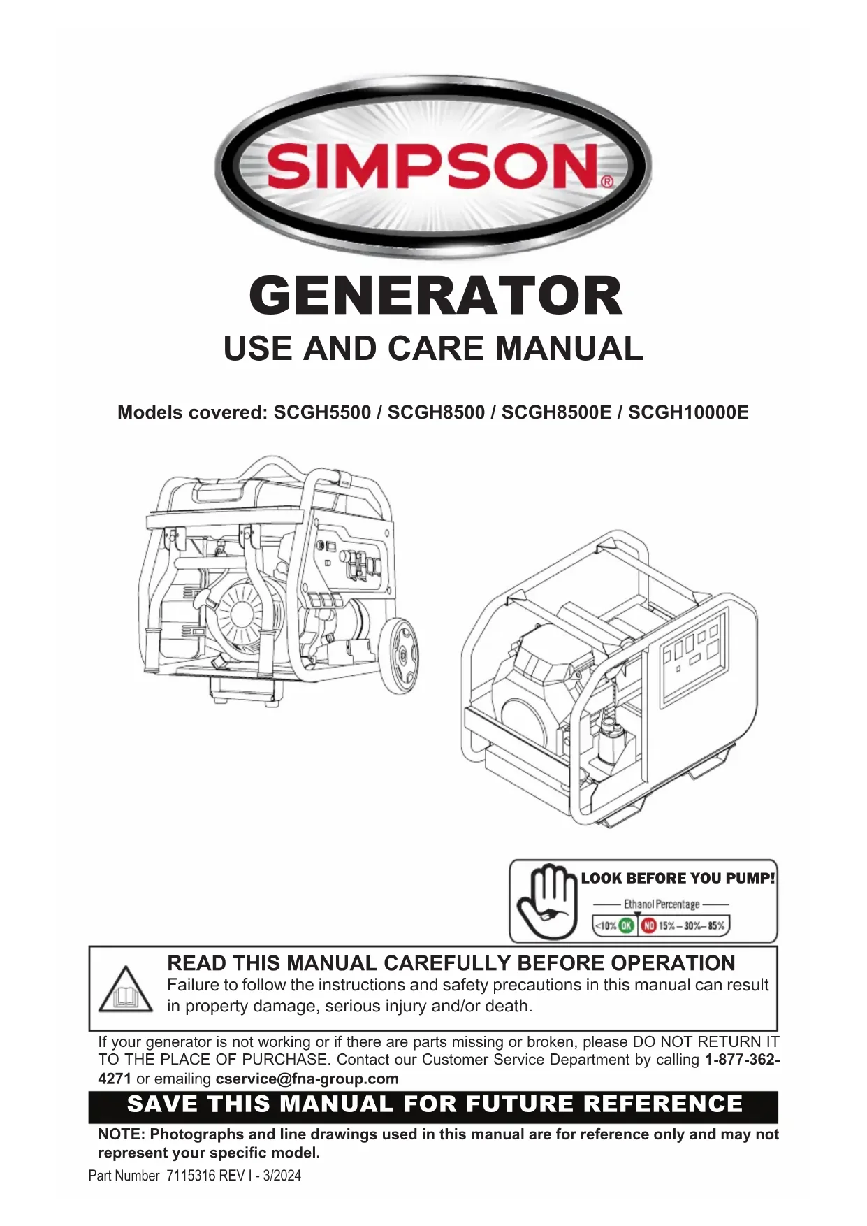
NOTE: Photographs and line drawings used in this manual are for reference only and may not represent your specific model.

CALIFORNIA PROPOSITION 65 WARNING
This product and the engine exhaust can expose you to chemicals which are known to the state of California to cause cancer, birth defects, or other reproductive harm. For more information on California Proposition 65, go to www.P65Warnings.ca.gov.

POLYCYCLIC AROMATIC HYDROCARBON WARNING
The air filter element and air box assembly may contain polycyclic aromatic hydrocarbons (PAHs). Some PAHs may cause cancer. To avoid exposure to PAHs, wear gloves when performing air filter maintenance.
SAVE THIS MANUAL FOR FUTURE USE
Keep this manual for future reference. This manual should be considered a permanent part of the product and stay with it. This manual should be available to anyone operating the product(s) it covers. This manual should remain with the product(s) it covers if sold to a new owner. If the manual becomes damaged, lost, or otherwise unusable, you may download a new copy from the product pages at www.simpsoncleaning.com or contact customer support by calling 1-877-362-4271.
Write down the model number, serial number, and purchase date of this product in the spaces provided below then keep this manual with the purchase receipt(s) for future reference.
Model Number:
Serial Number:
Purchase Date:
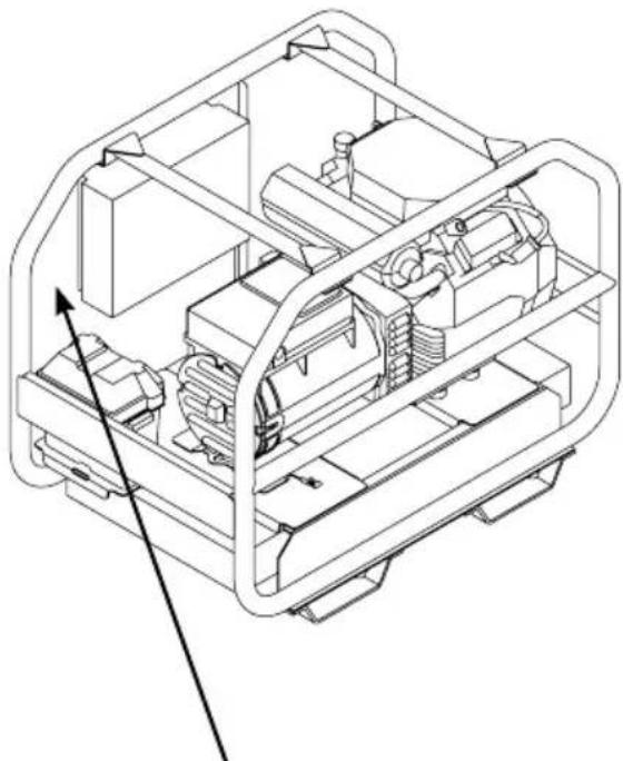
SCGH5500
SCGH8500
SCGH8500E
natural_image
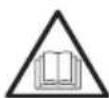
Technical line drawing of a mechanical housing or enclosure with three directional arrows pointing to internal components (no text or symbols)Model Data Decals Model Data Decal
SCGH10000
natural_image
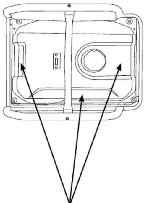
Technical line drawing of a mechanical device interior with internal components and mounting brackets (no text or symbols)SAFETY INSTRUCTIONS
Hazard Alert Symbols
Emission Information
Special Requirements
DISCLAIMERS
ASSEMBLY
Unpacking
Installing the Wheels - SCGH5500, SCGH8500(E)
Assembling and Installing the Support Bracket - SCGH5500, SCGH8500(E)
Installing the Wheel Set - SCGH10000
Installing the Handle - SCGH10000
Connecting Battery (Electric Start Models Only)
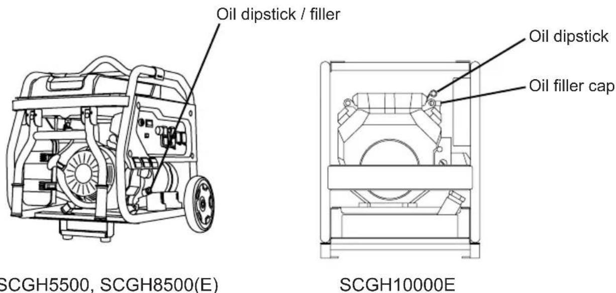
COMPONENT LOCATION
SCGH5500, SCGH8500(E)
SCGH10000E
CONTROL PANELS
SCGH5500
SCGH8500
SCGH8500E
SCGH10000E
HOUR METER
IDLE CONTROL
OPERATING CHECKLIST
Location
Operating Conditions
Grounding
Connecting Generator to the Electrical System of a Building
Checking the Engine Oil
Checking Fuel
STARTING THE ENGINE
4
4
5
5
5
6
6
6
7
8
9
10
11
11
13
15
15
15
15
16
17
17
18
18
19
20
20
21
23
25
CONNECTING DEVICES
Ground Fault Circuit Interrupt (GFCI)
Testing the GFCI receptacle(s)
Connecting Electrical Devices
Generator Load Capacity
Generator Load Chart
27
27
27
28
28
29
SHUTTING OFF THE ENGINE
MAINTENANCE
Generator Maintenance
Engine Maintenance
Cleaning
Battery Maintenance (Electric Start Models Only)
Engine Idle Adjustment
30
31
31
31
31
32
32
TROUBLESHOOTING
Generator Troubleshooting Chart
Engine Troubleshooting Chart
33
33
33
STORAGE AND TRANSPORTATION
Storing for Two Months or Less
Storing for More Than Two Months
Transportation
34
34
35
35
WIRING DIAGRAMS
SCGH5500
SCGH8500
SCGH8500E
SCGH10000E
36
36
37
38
39
SPECIFICATIONS
Model Number: SCGH5500 / Item Number: 70053
Model Number: SCGH8500 / Item Number: 70054
Model Number: SCGH8500E / Item Number: 70055
Model Number: SCGH10000E / Item Number: 70098
40
40
40
41
41
READ THIS MANUAL BEFORE OPERATING
This manual contains important safety information and instructions. Do not operate this product until you have read, and completely understand all safety, operation, and maintenance instructions listed in this manual. Failure to follow the information contained in this manual will result in property damage, injury, and/or death.
NOTE: The warnings and precautions discussed in this manual cannot cover all conditions and situations that may occur. The operator must understand awareness and caution are factors which cannot be built into this product and so must be exercised by the operator.
ADDITIONAL INSTRUCTIONS
Along with this manual, be sure to read any additional instructions provided both on and with the product, attached equipment, accessories, and the engine powering the product. Pay careful attention to all additional safety rules and instructions on proper startup, operation, and shutdown procedures. Always use any recommended protective apparel that may be needed to operate the equipment safely.
HAZARD ALERT SYMBOLS
Be sure to understand the safety symbols and definitions listed below. Each symbol contains one of four words: DANGER, WARNING, CAUTION, NOTICE, indicating different levels of hazard severity. These symbols are used throughout this manual and are followed information about a specific hazard, the consequences of the hazard, and instructions on how to avoid the hazard. Failure to heed these symbols and follow the instructions provided with them will result in property damage, injury, and/or death.

Indicates an imminently dangerous situation, which if not avoided, will result in property damage, serious injury, and/or death.

Indicates a potentially hazardous situation, which if not avoided, could result in property damage, serious injury, and/or death.

Indicates a hazardous situation, which if not avoided, could result in property damage and/or minor to moderate injury.

Indicates information considered important, but not directly hazard related.
Emission Information
The Environmental Protection Agency (and California Air Resource Board of generators certified to CA standards) requires that this generator comply with exhaust and evaporative emission standards. Locate the emissions compliance decal on the engine to determine what standards the generator meets and which warranty applies. This generator is certified to operate on gasoline.
The emission control system includes the following components (if equipped):
Air Induction System
- Intake pipe or manifold
- Air cleaner
Fuel System
- Carburetor
- Fuel tank and cap
- Fuel lines
• Evaporative vent lines - Carbon canister
Ignition System
- Spark plug
- Ignition module
Exhaust System
- Exhaust manifold
- Muffler
- Pulsed Air Valve
- Catalyst
Special Requirements
- In some areas, generators are required to be registered with local utility companies.
- If the generator is used at a construction site, there may be additional regulations which must be observed.
- There may be additional federal and/or state Occupational Safety and Health Administration (OSHA) regulations, local codes, or ordinances that apply to the intended use of the generator. Please consult a qualified electrician, electrical inspector, or the local agency having jurisdiction in your area.
DISCLAIMERS
- All information in this publication was based on the latest product information available at the time of printing. The FNA Group reserves the right to change, alter, and/or improve the product and this document at any time, without notice, and without incurring any obligation.
- The pictures and figures in this manual should be used for reference only. There may be differences between the pictures and figures and the physical product.
- This generator may be equipped with a spark arrestor muffler. If equipped, the spark arrestor must be maintained in effective working order by the owner/operator. In the State of California, a spark arrestor is required by law (Section 4442 of the California Public Resources Code). Other states may have similar laws. Federal laws apply on federal lands.
Follow the steps outlined in this section to unpack and assemble your generator. If you have any questions regarding the unpacking or assembly of your generator, please have your model number and serial number ready, then contact customer support at 1-877-362-4271 or email cservice@fna-group.com.
Unpacking
- Place the shipping carton on a solid, flat surface.
- Carefully cut the top of the carton open.
- Carefully cut each corner of the carton from top to bottom.
- Lay each side of the carton flat on the ground.
- Remove everything from the carton.
Installing the Wheels - SCGH5500, SCGH8500(E)
Slide the axle through the wheel, the first washer, frame mounting hole, and the second washer. Then insert the clip through the hole in the axle to secure the assembly. This process must be done on both sides of the generator.
NOTE: Generator wheels are not intended for over-the-road use.
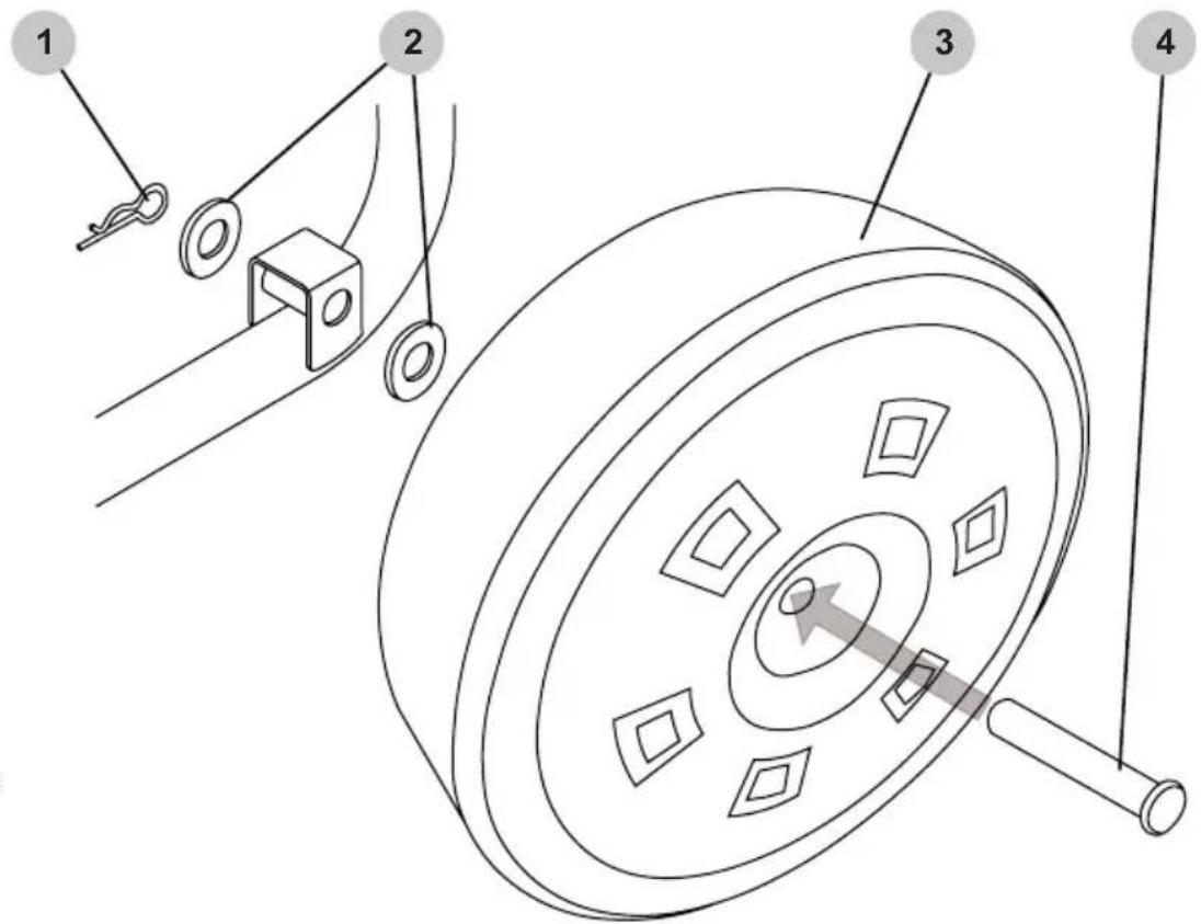
- Clip
- Washers
- Wheel
- Axle
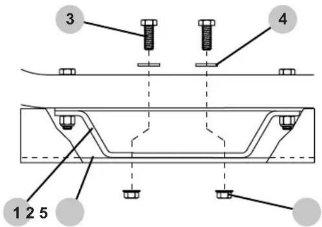
Assembling and Installing the Support Bracket
SCGH5500, SCGH8500(E)
Assembling bracket: If rubber feet are not already installed on the onto the support bracket, slide both M6x18 bolts through the rubber feet then through the support bracket, and tighten M6 nuts onto the bolts to secure the assemblies.
Installing assembled bracket: Slide both M8x16 bolts through the support bracket and frame, then tighten the M8 nuts onto the bolts to secure the assembly.
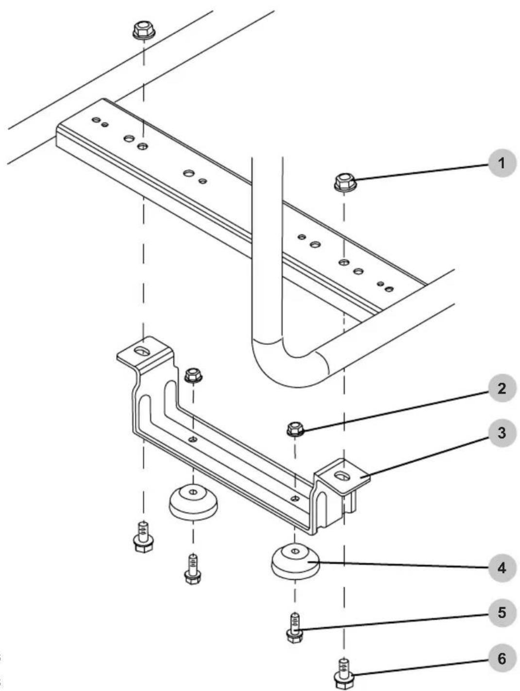
- M8 nuts
- M6 nuts
- Support bracket
- Rubber feet
- M6 x 18 bolts
- M8 x 16 bolts
Installing the Wheel set (optional)
SCGH10000E
- Slide the wheels onto the axles taking note to place the longer hub housing toward the frame. Slide the locking collars onto the axles to the wheels; tighten.
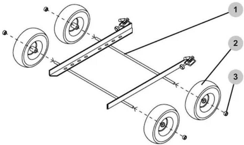
- Axle
- Wheel
-
Locking collar
-
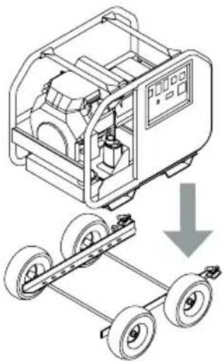
Carefully lower the generator onto the wheel set frame while aligning the mounting holes.
natural_image
Technical illustration of a mechanical device with wheels and a downward arrow indicating motion (no text or symbols)
WARNING:
The generator is very heavy. Use proper rigging when lifting the generator. Never stand under the generator while moving it.
DO NOT place your hand between the generator feet and the wheel set frame. Your hand may be crushed.
- Slide one 3/8" flat washer onto each 3/8 x 1" bolt. Inset the bolt through the generator foot and the wheel set frame. Thread on a 3/8" whiz nut; tighten.
- Generator foot
- Wheel set frame
- 3/8 x 1" bolt
- 3/8" flat washer
- 3/8" whiz nut
Installing the Handle (optional)
SCGH10000E
- Hold the handle to the left of the generator frame as shown below, then slide the handle toward the right onto the frame taking care to align the holes.
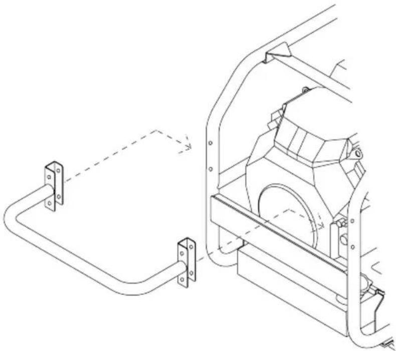
natural_image
Technical line drawing of a mechanical assembly with two components connected by a rod (no text or symbols present)- Place one flat washer on each bolt. Slide the bolts trough the handle bracket and the generator frame. Place one flat washer on the exposed threads of each bolt. Thread on one nylon-insert locknut onto each bolt; tighten.
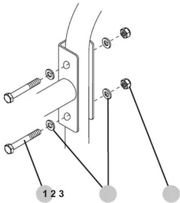
- M8 x 60mm bolt
- M8 flat washer
- M8 nylon-insert locknut
Connecting Battery (Electric Start Models Only)


ACID
Batteries contain sulfuric acid. Sulfuric acid is highly corrosive. Contact with skin can cause severe burns; contact with eyes can cause permanent blindness; and accidental ingestion can cause death. To avoid contact with sulfuric acid, always wear protective equipment when handling batteries. If acid contacts skin, flush are with cool water for 10-15 minutes. Immediately remove contaminated clothing and thoroughly wash the underlying skin.

BATTERY CONNECTIONS
Always remove the black, negative (-) battery cable first and always connect the black, negative (-) battery cable last. Failure to do this could cause metallic tools to short to the frame possibly causing burns or the battery to explode.
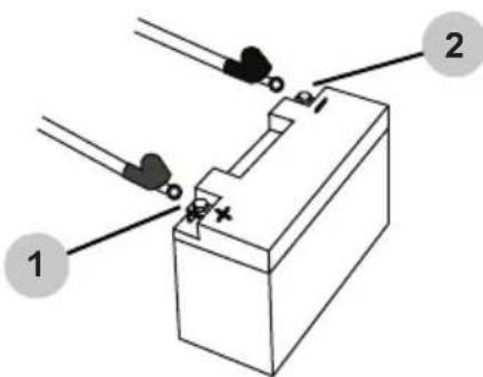
SCGH8500E
The battery included with the generator is a 12-volt, 11Ah, garden tractor style battery. To connect the battery, you will need to install the battery cables by following the steps outlined below.
- Remove battery terminal covers (if applicable).
- Connect red cable (1) to the positive (+) battery terminal with supplied bolt and nut.
- Connect black cable (2) to the negative (-) battery terminal with supplied bolt and nut.
- Make sure both the positive and negative connections are secure.
- Slide the rubber boots over both terminals and connection hardware.
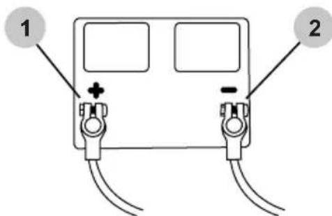
SCGH10000E
The battery included with the generator is a 12-volt, 36Ah, "U1" style battery. To connect the battery, you will need to install the battery cables by following the steps outlined below.
- Remove the cover from the battery box.
- Carefully place the battery into the battery box.
- Place the red, positive (+) battery cable (1) onto the positive (+) battery post. Tighten.
- Place the black, negative (-) battery cable (2) onto the negative (-) battery post. Tighten.
- Place the cover back onto the battery box.
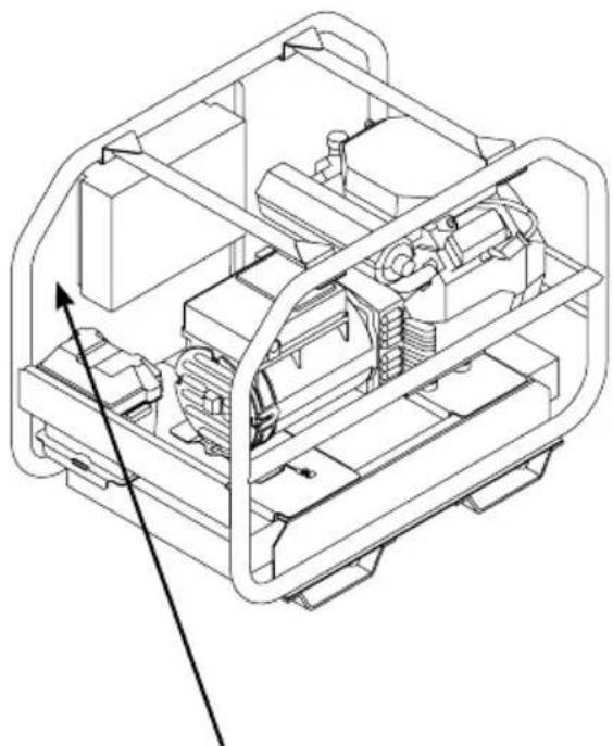
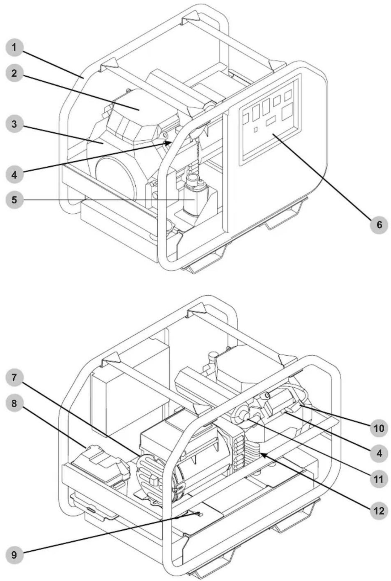
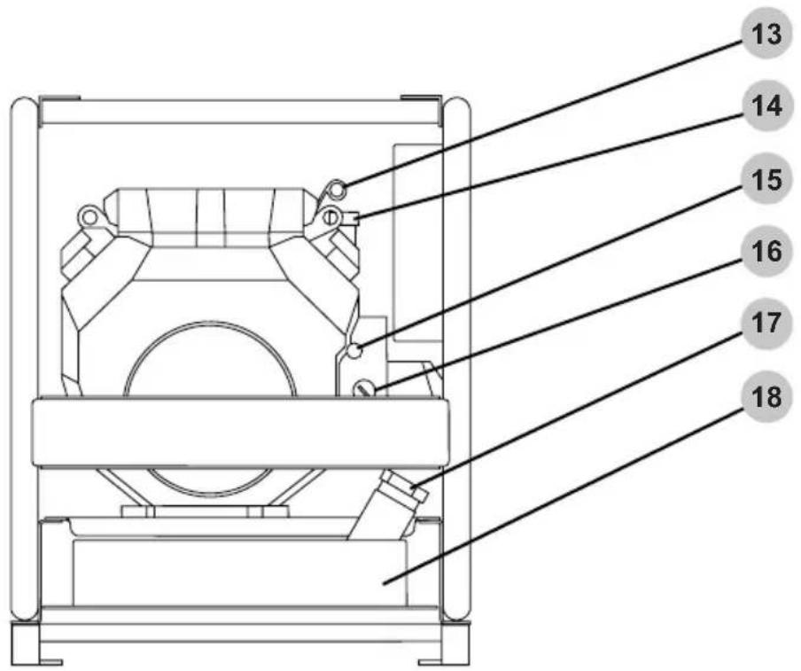
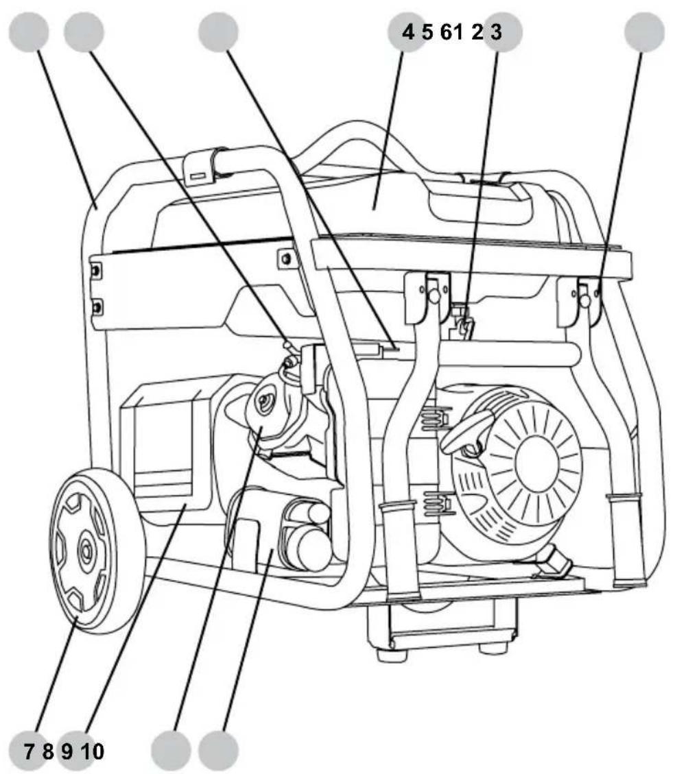
SCGH5500, SCGH8500(E)
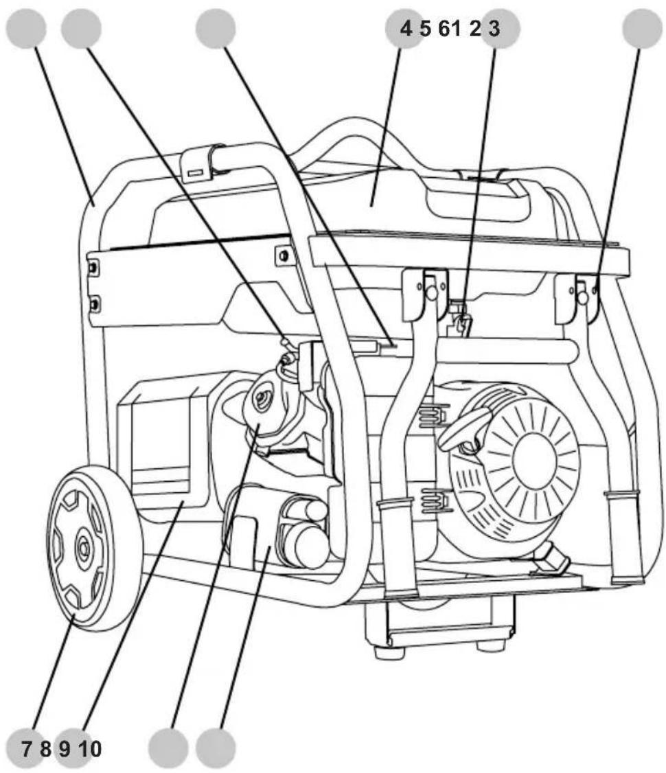
- Frame
- Spark plug
- Engine choke
- Fuel tank
- Fuel valve
- Handle stop pin
- Wheel
- Exhaust heat shield
- Engine cylinder head
- EVAP / carbon canister
NOTE: Line drawings used in this manual may not represent your specific model.
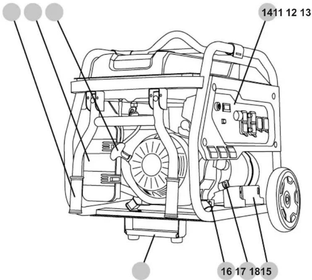
- Handle
- Air filter box
- Starter recoil
- Control panel
- Support bracket
- Engine oil drain plug
- Oil dipstick
- Battery tray (electric start models only)
- Fuel level indicator
- Fuel tank cap
- Frame ground terminal
- Spark arrestor (if equipped)
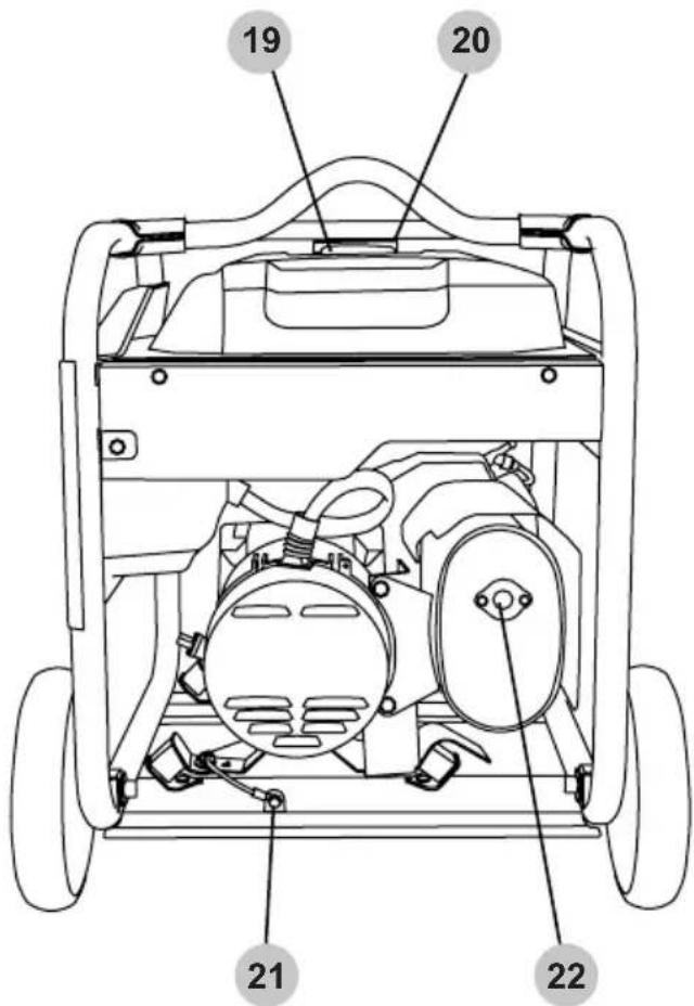
NOTE: Line drawings used in this manual may not represent your specific model.
- Frame
- Engine air filter box
- Dual cylinder engine
- Spark plug
- EVAP / carbon canister
- Control panel
- Alternator
- Battery box
- Frame ground terminal
- Engine fuel filter
- Spark arrestor (if equipped)
- Engine oil filter (not shown)
- Engine oil dipstick
- Engine oil filler cap
- Engine choke
- Engine ON/OFF switch
- Engine fuel filler cap
- Fuel tank
SCGH5500
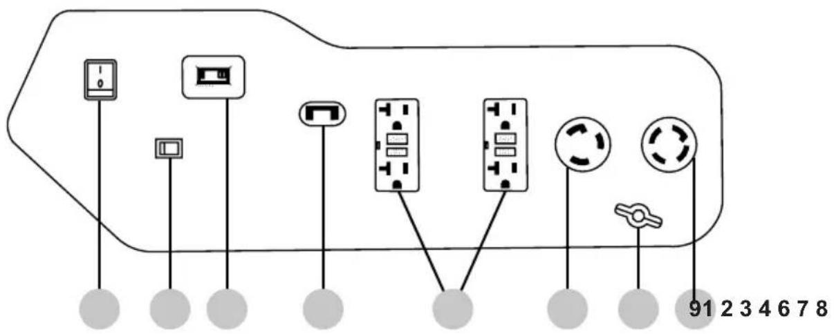
SCGH8500
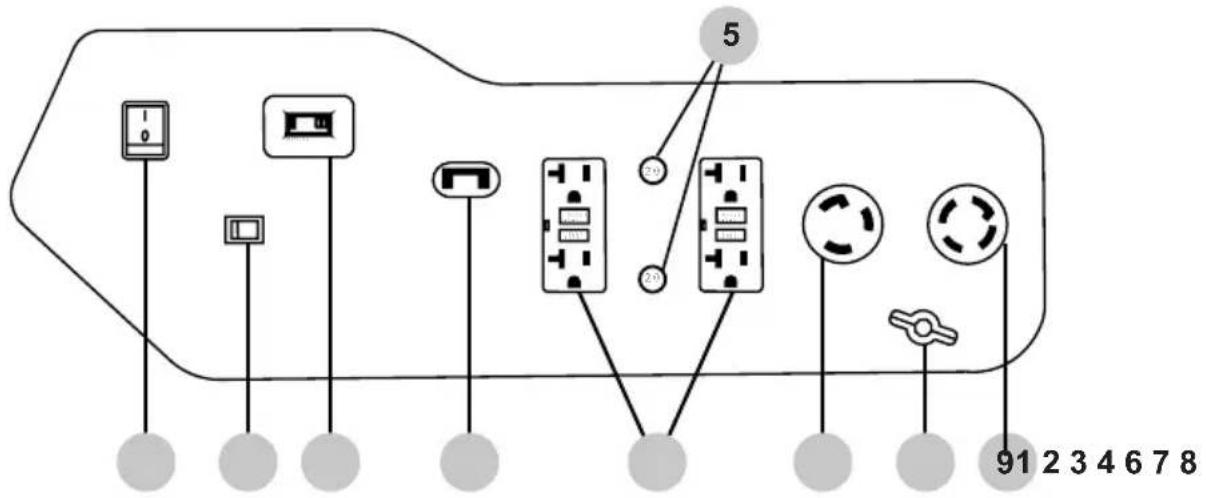
SCGH8500E
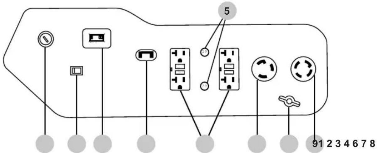
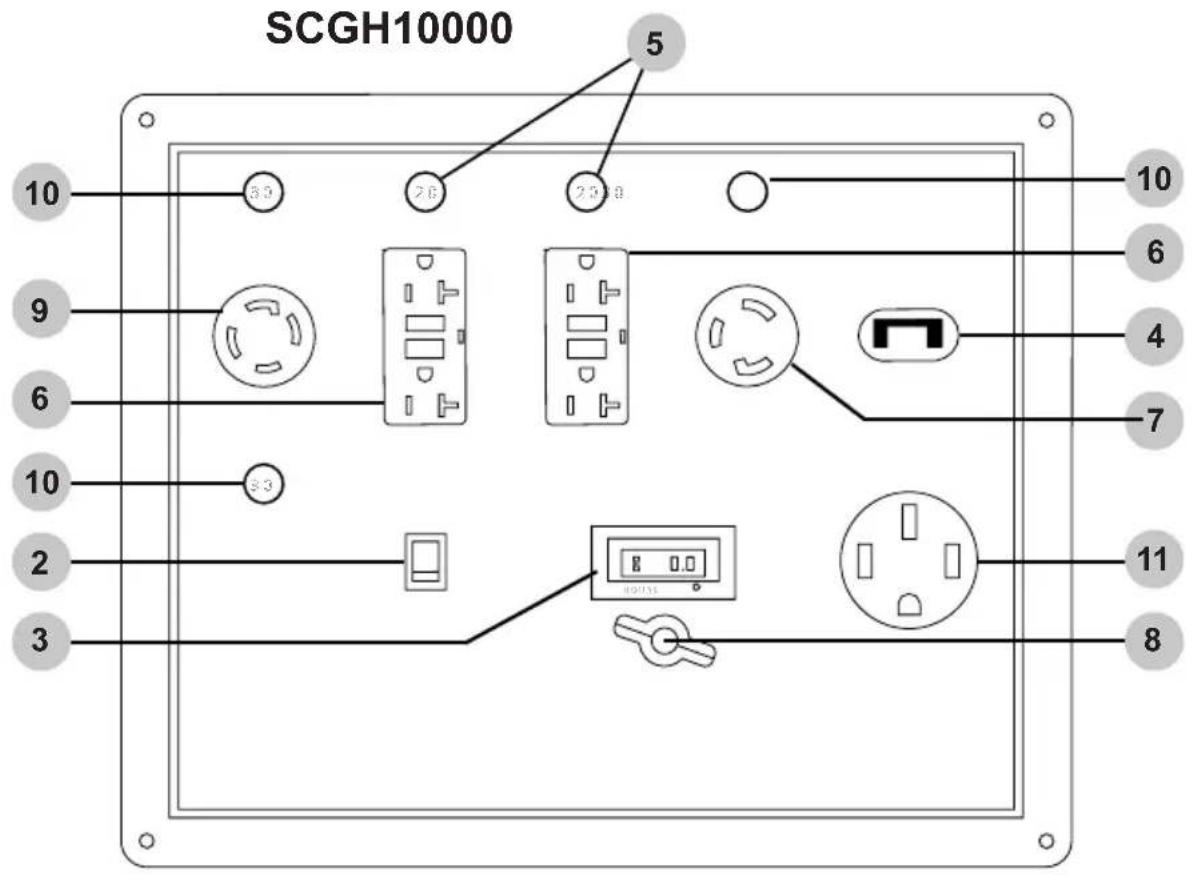
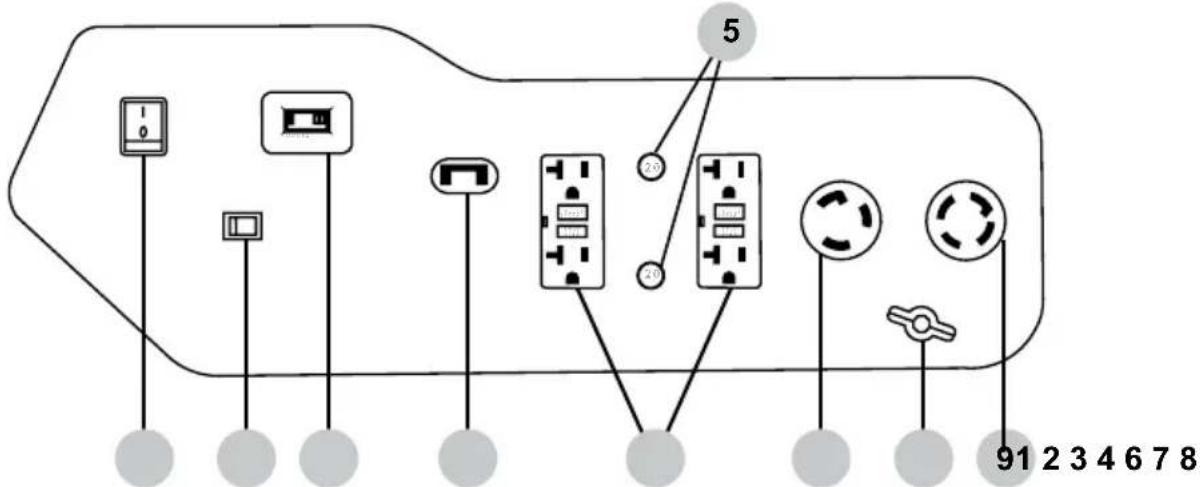
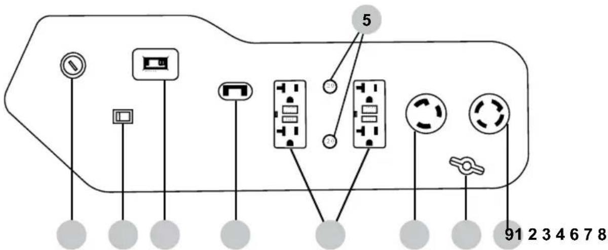
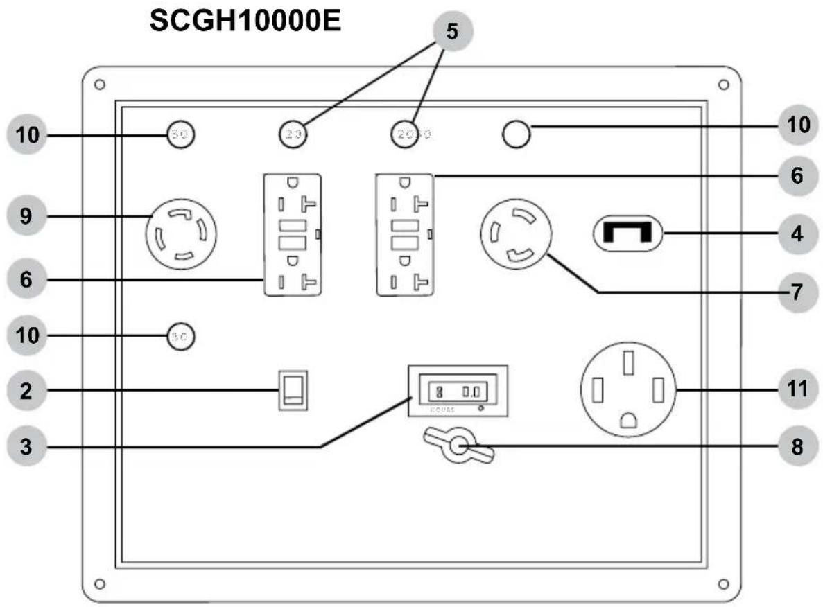
- Engine control switch
- Idle control switch (if equipped)
- Hour meter
- Main breakers - SCGH5500 17.5 amp, SCGH8500(E) 30 amp, SCGH10000 47 amp.
- Circuit breaker 20 amp
- 120v AC, single phase, 60Hz duplex GFCI receptacle, (NEMA 5-20R)
- 120v AC, single phase, 60Hz twist-lock receptacle, (NEMA L5-30R)
- Ground terminal
- 120 / 240v AC, single phase, 60Hz twist-lock receptacle, (NEMA L14-30R)
- Circuit breaker 30 amp
- 120 / 240v AC, single phase, (NEMA 14-50R)
Hour Meter
The hour meter keeps track of the time the generator is running. The hour glass icon flashes when the engine is running to signify the meter is tracking the hours of operation. The digital time display shows the recorded hours of operation. For hour meter location see the COMPONENT LOCATION section of this manual.
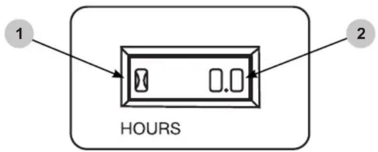
- Hour glass icon
- Digital time display
IDLE CONTROL (if equipped)
Idle Control
The idle control feature automatically reduces the engine speed when there is no electric load on the generator. The lower engine idle speed saves fuel, reduces engine wear, and lowers noise. The engine speed will automatically increase when an electric load is applied to the generator.
To activate the idle control feature, turn the idle control switch on. To deactivate the idle control feature, turn the idle control switch off. For idle control switch location, see the CONTROL PANELS section in this manual. The idle control feature should be off before starting or stopping the generator. Always allow the engine to warm up and the idle to stabilize before turning the idle control switch on, or placing an electrical load on the generator.
IDLE CONTROL SWITCH
Location
Only use the generator outside in a well-ventilated area and always carefully consider wind and air currents when running. Place the generator on a level surface before any operation and provide two (2) feet clearance on all sides of the engine while operating.
- Never use the generator inside a house, garage, or any other kind of enclosure, even if doors and windows are open.
• Install a carbon monoxide detector in any occupied buildings near the running engine. - If you experience headache, nausea, dizziness, sleepiness, or weakness while the generator is running, move to fresh air and seek medical attention immediately.


TOXIC FUMES
Engine exhaust contains carbon monoxide, an odorless, colorless, poisonous gas. Running an engine indoors will kill you in minutes. Never use this product inside a house, garage, or any other kind of enclosure even if doors and windows are open. Run engine outside at least 20 feet (6 meters) away from windows, doors, and vents. Carefully consider wind direction and air currents when using this product outside to avoid breathing in engine exhaust. Always use a carbon monoxide detector in any occupied buildings near the running engine.

Operating Conditions
Before starting engine, remove any excessive dirt and debris from cooling vents, exhaust, and starter recoil areas. Then, check for loose or damaged parts, oil or fuel leaks, and/or any other condition that may affect proper operation. Repair or replace all damaged or defective parts immediately. Always keep all safety guards in place and in proper working order. For safety reasons, the manufacturer recommends all maintenance and repairs be performed by an authorized service center. Never move or tip the generator while operating. Use generator only for its intended purpose. If you have questions about the proper use of your generator, please contact customer support at 1-877-362-4271 or cservice@fnagroup.com.


UNTRAINED OPERATION
Untrained persons, young children, and pets can be seriously injured or killed if allowed to incorrectly operate or play with a running generator. Be sure anyone operating the generator receives proper instructions, understands safe operation, and has read the owner's manual before operating this product. Do not let children operate the generator without parental supervision. Keep young children and pets away from the generator while it is running. Always turn the generator off before leaving the area.


Failure to inspect this product before use could result in a hazardous situation resulting in product damage serious injury and/or death. To avoid these hazards, inspect the generator before each use. Check for loose or damaged parts, signs of oil or fuel leaks, missing guards, plugged cooling vents, or any other condition that may affect proper operation. Repair or replace all damaged or defective parts and keep all safety guards in place and in proper working order before using the generator.


HOT SURFACES
A running engine produces heat. The surfaces of the engine, related components, and engine exhaust gas get hot enough to cause mild moderate burns or ignite materials on contact. To avoid burns, do not touch engine surfaces or exhaust gases while operating and allow engine to cool completely before moving, touching, or performing any maintenance. To avoid a fire, keep all flammable materials at least five feet away from all sides of the product.


MOVING PARTS
This product has many parts that move at high speeds. Moving parts can cause crushing injuries, broken bones, severe lacerations, and/or traumatic amputations. To prevent injury, never place fingers, hands, feet, or other body parts near running engine. Never operate product with covers, shrouds, or other guards removed. Do not wear loose-fitting clothing, dangling drawstrings, or any other hanging items that could become entangled in moving parts while operating. Tie up long hair and remove jewelry before operating.
Grounding
Grounding the generator helps prevent electrical shock if a ground fault condition develops in the generator or in connected electrical devices. Proper grounding also helps dissipate static electricity, which often builds up in ungrounded devices. Grounding a generator with a wheel kit installed is especially important. The generators covered in this manual have two ground terminals, one on the frame and one on the control panels. For ground terminal location(s) see the COMPONENT LOCATION section of this manual. It is strongly recommend that you refer to NEC 250.34 (sections A,B, and C) and/or consult with a local electrician for grounding requirements in your area before operating the generator.

GROUNDING
Failure to properly ground your generator will create an electrical shock hazard that could result in severe injury or death. To prevent an electric shock hazard, be sure to provide the correct ground for the desired use of the generator per the National Electric Code (NEC) 250.3 (sections A,B,and C) or consult with a local electrician to learn the appropriate grounding requirements.

ELECTROCUTION
Do not connect devices with worn, frayed, bare, or otherwise damaged electrical cords to the generator. Electrical shorts caused by damaged wiring can damage the generator and touching live damaged electrical cords or bare wires will cause serious injury or death. To avoid these electrocution hazards, inspect all electrical cords before using them and do not use any cords that are damaged or showing bare wires.
Connecting Generator to the Electrical System of a Building
Do not attempt to backfeed power into your house from the generator. Backfeeding is trying to power your home by plugging the generator into a wall outlet. Backfeeding can damage electrical devices in your home, start an electrical fire, and cause severe injury or death to utility workers and others on your electrical grid.
Using a transfer switch is recommended when connecting a generator directly to a building's electrical system. Connections for a portable generator to a building's electrical system must be made by a qualified electrician and in strict compliance with all national and local electrical codes and laws.

BACKFEEDING
Backfeeding can damage electrical devices in your home, start an electrical fire, and may cause severe injury or death to utility workers and others on your electrical grid. To prevent backfeeding, do not plug the generator into your home's outlets and have a qualified electrician install the generator if used as a back up power source.
Checking the Engine Oil

HOT OIL
Hot oil can cause serious burns. To prevent getting burned when changing or checking the engine oil, wear appropriate gloves and change the oil when the engine is warm but not hot.
NOTICE
LOW OIL SENSOR
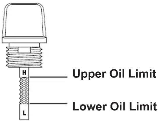
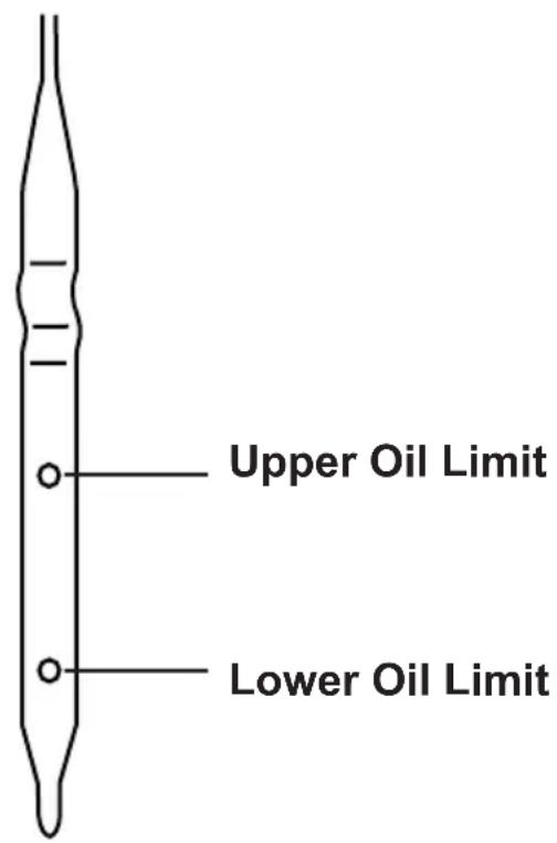
The low oil sensor (if equipped) will automatically stop the engine when the oil level falls below the safe limit. To avoid an unexpected shutdown, check the oil level before each use, fill to the upper limit, and always operate engine on a level surface.

NOTICE
FILL ENGINE OIL BEFORE USE
The engine is shipped from the factory without oil. Running the engine without oil will result in severe engine damage and void the warranty. To avoid causing engine damage and voiding the warranty, fill the engine with the recommended oil type before starting.
NOTICE
USE CORRECT ENGINE OIL
Oil is a major factor in the performance and service life of any engine. Using the incorrect oil may damage the engine and void the warranty. To avoid causing engine damage and voiding the warranty, check and change oil as required using the correct engine oil.
SCGH5500, SCGH8500(E)
- Check oil with generator on a level surface and the engine off.
- Unscrew the engine oil dipstick and pull it out, then wipe dipstick clean.
- Place clean dipstick into filler neck but do not thread it in, leave it to rest on the filler neck.
- Remove the dipstick from filler neck and check oil level. Oil level should be between the upper and lower oil limits on the dipstick.
- If level is low, add the recommended oil to the crankcase until the level reaches the upper limit on the dipstick. See the engine manual for recommended oil.
- Install the dipstick and tighten cap by threading it into the filler neck.
SCGH10000E
- Check oil with generator on a level surface and the engine off.
- Fully pull the engine oil dipstick out then wipe the dipstick clean.
- Place the clean dipstick fully into the dipstick tube.
- Remove the dipstick and check oil level. Oil level should be between the upper and lower oil limits on the dipstick.
- If level is low, add the recommended oil to the crankcase until the level reaches the upper limit on the dipstick. See the engine manual for recommended oil.
- Place the dipstick fully into the dipstick tube.
Checking Fuel


REFUELING
Gasoline is highly flammable and gasoline vapors are extremely explosive. Fire and explosions can cause severe burns and/or death. Keep gasoline away from flames, sparks, and other ignition sources. Refuel outdoors in a well-ventilated area with the engine stopped and cool. Wipe up any spilled gasoline and allow engine to dry before starting. Keep a fire extinguisher handy while refueling. Do not operate engine with leaks in the fuel system. Do not store gasoline near other flammable materials.
NOTICE
OLD FUEL
Old gasoline can create deposits that clog fuel systems causing hard starting and poor performance. Damage caused by old fuel is not covered by warranty. To minimize deposits, avoid old fuel related performance issues, and prevent costly repair work, do not use gasoline that is older than 30 days.
NOTICE
ALCOHOL BLENDS
Using gasoline with an alcohol blend greater than 10% (E10) will damage the engine. Damage caused by using an alcohol blend of 15% (E15), 85% (E85), or any other alcohol blend higher than 10% (E10) is not covered under warranty. To avoid engine damage caused by an alcohol blend that is too high, use gasoline with 10% (E10) alcohol or less.
NOTICE
FUEL ADDITIVES
The use of fuel system cleaning additives can damage the engine and fuel systems. Damage caused by the use of fuel system cleaning additives is not covered by warranty. To avoid engine and fuel system damage, do not use any fuel system cleaning additives.
! CAUTION:©
FUEL TANK PRESSURE
Gasoline vapor can build up inside the fuel tank creating pressure. This pressure may increase when the engine is hot from running. Opening the fuel tank under pressure can cause rapid escape of flammable vapors and possible fuel spills that may ignite from contact with hot engine surfaces resulting in burn hazard. To avoid rapidly escaping fuel vapor, always allow the engine to cool for at least two (2) minutes before removing fuel cap and loosen the fuel cap slowly to relieve any pressure in the tank.
NOTICE
GASOLINE STORAGE
It is important to prevent gum deposits from forming in essential fuel system parts, such as the carburetor, fuel filter, fuel hose or tank during storage. Alcohol-blended fuels (also called gasohol, ethanol, or methanol) attract moisture, which leads to separation and formation of acids during storage. Acidic fuel and gum deposits can damage the engine's fuel system while in storage. Effects of old, stale, or contaminated fuel are not covered under warranty.
NOTE: Using a fuel stabilizer when storing gasoline will help prevent problems related to ethanol alcohol in outdoor power equipment engines. Always follow the instructions provided by the fuel stabilizer manufacturer to mix and use correctly.
NOTICE
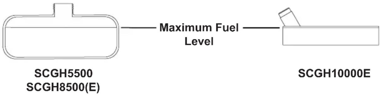
DO NOT OVERFILL FUEL TANK
Overfilling the fuel tank can result in carbon canister damage (if equipped), poor engine performance, and void the warranty. To avoid damaging the carbon canister, poor engine performance, and voiding the warranty, do not fill the fuel tank above the maximum level.
- Check fuel with generator on a level surface with the engine off.
- Read fuel gauge (if equipped) and fill fuel tank if needed. For fuel gage location see the COMPONENT LOCATION section of this manual.
- Do not use gasoline that is older than 30 days. Use only clean and fresh regular unleaded gasoline with a minimum octane rating of 87. Do not mix oil with gasoline. Do not use gasoline that contains more than 10% ethyl alcohol. E15, E20, and E85 are not approved fuels and should not be used.
- Do not to fill the fuel tank above the maximum fuel level to allow room for fuel expansion. For fuel capacity see the SPECIFICATIONS section of this manual.
- Follow the steps in the OPERATING CHECKLIST section of this manual. If needed, refer to your Engine Owner's Manual for specific starting instructions.

OPERATING CHECKLIST
Attempting to start the engine incorrectly or using the generator incorrectly can result in engine and/or generator damage, and may cause serious injury or death. To avoid engine and/or generator damage and serious injury or death be sure to read, understand, and follow the steps outlined in the OPERATING CHECKLIST section of this manual before starting the engine, and follow all the guidelines for proper use of the generator.
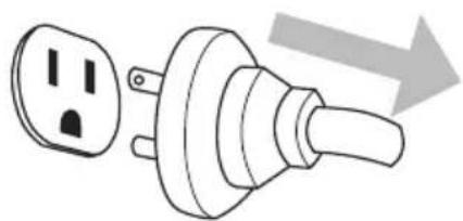
- Make sure there are no devices plugged into the generator outlets.
natural_image
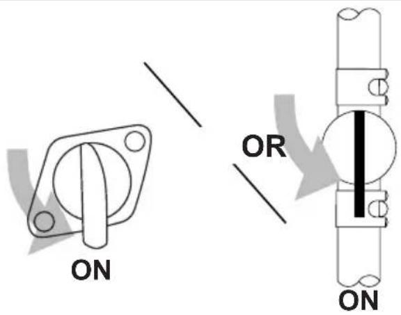
Diagram of a plug with two outlets and a handle, showing an arrow indicating direction (no text or symbols present)- Turn fuel valve (if equipped) to the ON position. For fuel valve location see the COMPONENT LOCATION section of this manual.
- Adjust choke as needed.
NOTE: The starting position of the choke will vary depending on the engine temperature. If starting a cold engine, move the choke lever towards the closed position. If starting a warm engine, move the choke lever towards the open position.

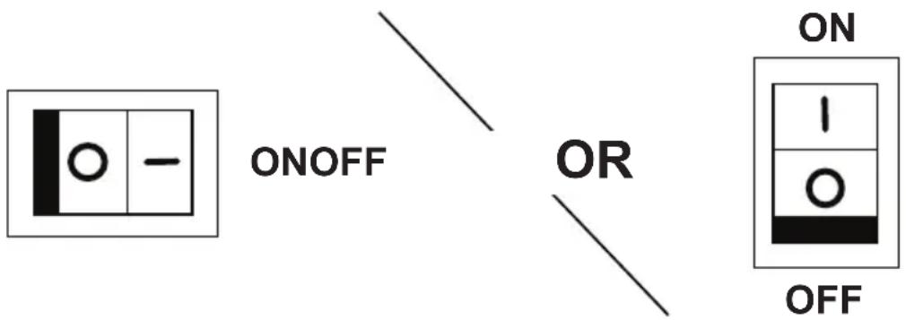
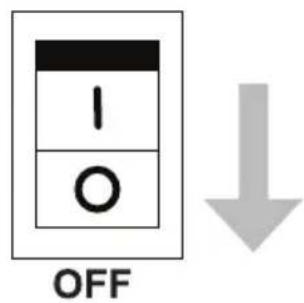
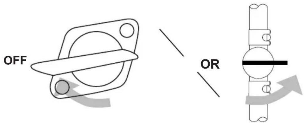
- Turn the engine idle control switch (if equipped) to the OFF position.
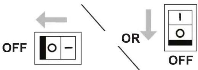
flowchart
graph TD
    A["OFF"] --> B["OR"]
    B --> C["OFF"]
    style A fill:#f9f,stroke:#333
    style B fill:#ccf,stroke:#333
    style C fill:#cfc,stroke:#333
- Start the engine.
NOTE: This manual covers generator models that feature both electric and manual start. Refer to the CONTROL PANELS section of this manual to determine if your model is electric or manual start, then follow the sequence below that is relevant to your model.

RAPID RETRACTION
Rapid retraction (also known as kickback) of the engine recoil starter cord will pull your hand and arm towards the engine faster than you can let go of the handle resulting in sprains, broken bones, lacerations, and/or traumatic amputations. Kickback is caused by damage to the engine crankshaft key, compression release failure, and/or improper starting techniques. To avoid kickback follow the appropriate maintenance schedule, starting instructions, and have repair work done by an authorized service center.
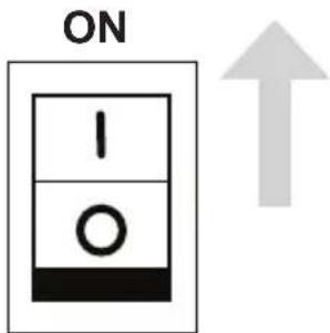
Electric Start Models Manual Start Models
A. Use key to turn the engine control switch to the START position then release key when engine starts.

natural_image
Symbol of a crossed-out circle with an arrow indicating direction (no text or numbers present)B. The engine control switch stays in the RUN position during operation.

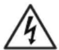
A. Turn the engine control switch to the ON position.
B. Pull the starter recoil.

natural_image
Simple line drawing of a hand holding a tool with two arrows indicating upward motion (no text or symbols)- After the engine is running, move the choke lever towards the open position.

- Allow the engine to warm up and the idle to stabilize before connecting any devices or turning the idle control switch on.

ELECTROCUTION
Do not connect devices with worn, frayed, bare, or otherwise damaged electrical cords to the generator. Electrical shorts caused by damaged wiring can damage the generator, and touching live damaged electrical cords or bare wires will cause serious injury or death. To avoid these electrocution hazards, inspect all electrical cords before using them and do not use any cords that are damaged or showing bare wires.
Ground Fault Circuit Interrupt (GFCI) (if equipped)
Your generator may be equipped with ground fault circuit interrupting (GFCI) receptacles. The purpose of these devices are to protect you from electrical shock in the instance where an electrical fault is located within your connected device(s).
The GFCI monitors the amount of current flowing to and returning from your connected device. Should the amount of current returning be lower than the amount flowing to the device, the GFCI will “trip”, instantly stopping the flow of electricity. Should the GFCI continuously trip when a device is connected, this is an indication that an electrical fault is located within the device and it should be serviced by an qualified electrical technician before further usage. It is imperative that you test the GFCI unit(s) each time the generator is to be used.
Testing the GFCI receptacle(s)
- Start the generator as indicated on pages 25 and 26.
- Turn the circuit breaker(s) ON if they are in the OFF position.
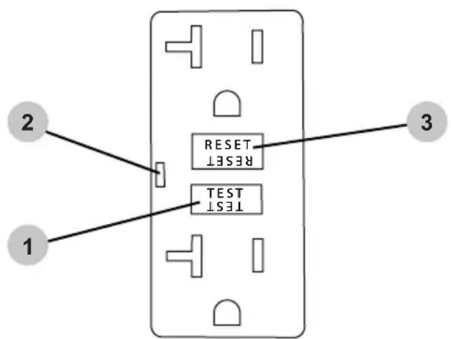
- Press the TEST button (1) on the GFCI receptacle(s). You should hear a "click" or "snap" sound and the LED indicator (2) will illuminate, (if equipped).
- Press the RESET button (3) to energize the receptacle; the LED will go dark.
Should the above test fail, discontinue use of the generator until it can be serviced by a qualified service technician.
Connecting Electrical Devices
- Allow the engine to warm up and the idle to stabilize before connecting any devices.
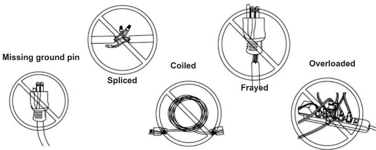
- Inspect power cord for damage before using. Do not connect any electrical devices with cords or plugs showing signs of damage from crushing, cutting, or heat, or other. Never use cords that are coiled; always uncoil cords before using.
- Make sure electrical devices are off before connecting them to the generator.


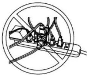
FIRE HAZARD
DO NOT use extension cords in the following conditions:
Generator Load Capacity
- Before connecting any devices, you must make sure your generator can supply enough rated (running watts) and starting (surge watts) for the electrical devices you wish to power. Exceeding the capacity of generator can damage the generator and/or electrical devices connected to it. Follow the instructions in this section to be sure you do not exceed the maximum output of the generator.
- Calculating Device Wattage Requirement: Every electrical device has a stated amount of power it needs to operate correctly. Expressed in watts, the power requirement can vary widely depending on the device. To find the wattage, first look in the owners manual of the device. If you do not have the manual, look for a nameplate on the device itself. Many will give you the wattage, but some may only indicate the current requirement (amperage). To find the wattage, simple multiply the current by the operating voltage. For example, a saw has a current requirement of 5.5 amperes at 120 volts. Multiplying 5.5 by 120 gives a wattage of 660.
- Understanding Device Surge: Devices with inductive loads (motors, transformers, ballasted lights) require more power to start than they require to run. Called surge watts, this extra amount of starting power may only last a second or two as the device powers up, but it must be considered to avoid exceeding the generator's maximum starting output. Surge watts are typically three (3) times higher than the required running watts. For example, a 800-watt motor will require about 2400 watts to start.
- To power multiple devices at the same time you will first need to be sure the surge from all the devices you wish to power does not exceed the maximum starting watts the generator can provide. Second, you must add up all the device running watts and make sure the total does not exceed the maximum running wattage the generator can provide.
- Refer to the GENERATOR LOAD CHART in this manual for estimated running watts of common electric devices.
Generator Load Chart
Do not overload the generator. Overloading the generator may damage the generator and/or the devices plugged into the generator. Refer to the chart below to understand the loads electrical devices create when running.
| Device Running Watts | |
| Air Conditioner(12,000 Btu) | 1700 |
| Air Conditioner(24,000 Btu) | 3800 |
| Air Conditioner(40,000 Btu) | 6000 |
| Battery Charger(20 Amp) | 500 |
| Belt Sander (3") 1000 | |
| Chain Saw 1200 | |
| Circular Saw (6-1/2") 800 - 1000 | |
| Clothes Dryer (Electric) 5750 | |
| Clothes Dryer (Gas) 700 | |
| Clothes Washer 1150 | |
| Coffee Maker 1750 | |
| Compressor (1 HP) 2000 | |
| Compressor (3/4 HP) 1800 | |
| Compressor (1/2 HP) 1400 | |
| Curling Iron 700 | |
| Dehumidifier 650 | |
| Disc Sander (9") 1200 | |
| Edge Trimmer 500 | |
| Electric Blanket | 400 |
| Electric Nail Gun | 1200 |
| Electric Range(Per element) | 1500 |
| Electric Skillet | 1250 |
| Freezer | 700 |
| Furnace Fan (3/5 HP) | 875 |
| Garage Door Opener | 500 - 750 |
| Hair Dryer 1200 | |
| Hand Drill | 250 - 1100 |
| Device Running Watts | |
| Hedge Trimmer | 450 |
| Impact Wrench | 500 |
| Iron | 1200 |
| Jet Pump | 800 |
| Lawn Mower 1200 | |
| Light Bulb | 100 |
| Microwave Oven 700 | - 1000 |
| Milk Cooler | 1100 |
| Oil Burner on Furnace 300 | |
| Oil Fired Space Heater (140,000 Btu) | 400 |
| Oil Fired Space Heater (85,000 Btu) | 225 |
| Oil Fired Space Heater (30,000 Btu) | 150 |
| Paint Sprayer, Airless (1/3 HP) | 600 |
| Paint Sprayer, Airless (Handheld) | 150 |
| Radio | 50 - 200 |
| Refrigerator | 700 |
| Slow Cooker 200 | |
| Submersible Pump (1-1/2 HP) | 2800 |
| Submersible Pump (1 HP) | 2000 |
| Submersible Pump (1/2 HP) | 1500 |
| Sump Pump | 800 - 1050 |
| Table Saw (10") | 1750 - 2000 |
| Television | 200 - 500 |
| Toaster | 1000 - 1650 |
| Weed Trimmer 500 | |
All the listed running watt ratings in this table are approximate. Please refer to the device's manual or contact the device's manufacturer for exact running and starting watts.
NOTE: Starting a device can require as much as three (3) times the running watts.
SHUTTING OFF THE ENGINE
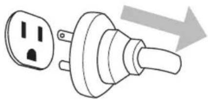
- Turn off and unplug all devices from the generator outlets.
natural_image
Diagram of a plug with two outlets and a handle, showing a right-pointing arrow (no text or symbols)- Turn off the engine.
NOTE: This manual covers generator models that feature both electric and manual start. Refer to the CONTROL PANELS section of this manual to determine if your model is electric or manual start, then follow the sequence below that is relevant to your model.
Electric Start Models
Use key to turn the engine control switch to the OFF position.

Manual Start Models
Turn the engine control switch to the OFF position.
- Turn fuel valve (if equipped) to the OFF position. For fuel valve location see the COMPONENT LOCATION section of this manual.
- Allow the engine to cool completely before storing.


MAINTENANCE
Improper engine and generator maintenance and failing to correct problems before operation could void the warranty and may result in property damage and injury. To prevent these hazards, follow the maintenance procedures and timelines listed in this manual and any other manual that came with this product.
Generator Maintenance
For safety reasons, the manufacturer recommends all generator service and repairs be performed by a qualified service center. Normal maintenance, replacement, and / or repair of emission control devices or systems may be performed by any establishment or individual. However, all warranty replacements or repairs must be performed by an authorized service center. To find an authorized service center near you, to make a warranty claim, or for authorized warranty repair, call 1-877-362-4271 or email cservice@fna-group.com.
It is the responsibility of the owner and/or operator to have all scheduled maintenance completed before operating the generator. Before servicing or inspecting the generator, stop the generator, disconnect all electrical devices and battery (if equipped), and allow the generator and engine to cool down.
NOTE: The Generator Maintenance section refers to all parts of the generator except engine. Please refer to the engine manual for engine maintenance information.
Engine Maintenance
Refer to the engine manual for all engine maintenance information.
Cleaning
Always clean the generator with the engine off and cool. To clean the generator, first use an air compressor set at no more than 25 PSI to clear dirt and debris from the generator surfaces, vents, and cooling slots. Then, wipe the exterior clean with a damp cloth.

NOTICE
CLEANING
Water can damage the generator windings and other components if allowed to enter through cooling slots or other holes. Damage caused by water intrusion is not covered under warranty. To avoid damaging the generator, do not use a pressure washer, garden hose, or any other sources of running water to clean the generator, and never submerge the generator in any liquids.
Battery Maintenance (Electric Start Models Only)
Batteries slowly lose strength when sitting idle through a process called self-discharge. If a battery is allowed to discharge past a certain point, it cannot be recharged and must be replaced. Therefore, it is best to keep the battery fully charged at all times to achieve maximum service life.
Because batteries for the electric start generator models covered in this manual are sold separately, and because there are different styles of batteries available, it is always best to follow the battery manufacturer's recommendations when handling, charging, storing, servicing, or replacing a battery.


EXPLOSIVE GAS
Batteries produce hydrogen gas while charging. If exposed to an ignition source, hydrogen gas can explode possibly causing property damage, serious injury and/or death. To avoid a hydrogen gas explosion, charge batteries in a well-ventilated place away from open flames, sparks, or any other sources of ignition.


ACID
Batteries contain sulfuric acid. Sulfuric acid is highly corrosive. Contact with skin can cause severe burns; contact with eyes can cause permanent blindness; and accidental ingestion can cause death. To avoid contact with sulfuric acid, always wear protective equipment when handling batteries. If acid contacts skin, rinse the area with cool water for 10-15 minutes. Immediately remove contaminated clothing and rinse the underlying skin with cool water for 10-15 minutes.
Engine Idle Adjustment
The engine idle speed is set at the factory and should not require user adjustment. Tampering with the governor can damage your engine and/or generator and will void the warranty.


IDLE ADJUSTMENT
Improper adjustment of the engine idle speed can damage you engine and/or generator set and will void the warranty. Any inspection and or adjustment of the engine idle should be done by an authorized service center. Tampering with or modifying the engine speed governor can damage you engine and/or generator set and will void the warranty.


MODIFICATION
The generator and engine are factory set to supply the correct frequency and voltage when running. Tampering with the factory governors and adjustments could damage the generator and will void your warranty. To avoid damaging the engine or generator set, do not modify the generator settings or not adjust the engine speed.
Generator Troubleshooting Chart
| Problem Possible Causes Solutions | ||
| Generator has no output | Circuit breakers are off | Unplug all devices and reset all the circuit breakers to the ON position |
| Device or cord failure | Unplug device and check the cord and the device for damage or lose connections. | |
| Generator needs service | Take to an authorized service center. | |
Engine Troubleshooting Chart
| Problem Possible Causes Solutions | |
| Engine will not startFor more information refer to the engine manual. | Engine control switch is in the OFF position. |
| Choke not set correctly | |
| Empty fuel tank | |
| Fuel not reaching carburetor | |
| Low engine oil | |
| Spark plug in bad condition | |
| Fuel old or stale | |
| Engine needs service |
NOTICE
GASOLINE STORAGE
It is important to prevent gum deposits from forming in essential fuel system parts. Alcohol-blended fuels (also called gasohol, ethanol, or methanol) attract moisture, which leads to fuel separation and the formation of acids during storage. Acidic fuel and gum deposits can damage the engine's fuel system. Effects of old, stale, or contaminated fuel are not covered under warranty.
NOTE: Using a fuel stabilizer such as Ethanol Shield™ (sold separately) when storing gasoline will help prevent problems related to alcohol blended fuels in outdoor power equipment engines. Always follow the instructions provided by the fuel stabilizer manufacturer to mix and use correctly.
Storing for Two Months or Less
- Fill fuel tank per the OPERATING CHECKLIST section of this manual and add a fuel stabilizer created for alcohol blended fuels.
- Start the engine per the STARTING section of this manual and run it for ten (10) minutes to allow the stabilized fuel circulate through the entire fuel system.
- With the engine still running, turn the fuel valve to the OFF position and allow the engine to run until it stalls from lack of fuel.
- Allow the engine to cool completely.
- Clean the generator per the MAINTENANCE section of this manual.
- On electric start models, remove the battery and place it on a smart charger per the MAINTENANCE section of this manual.
- Store the generator and battery in a clean, dry area that is out of direct sunlight.
Storing for More Than Two Months
- Make sure the engine is completely cool.
- Turn the fuel valve to the ON position.
- Remove all the fuel from fuel tank, fuel lines, and carburetor by loosening the drain screw at the bottom of the carburetor, then drain fuel into an appropriate container.
- Turn the fuel valve to the OFF position.
- Change the engine oil.
- Remove any dirt and debris from the area around the spark plug, then Use a spark plug socket or wrench to remove the spark plug.
- Pour .5 ounces (15 ml) of new oil into the engine combustion chamber, then slowly crank the engine by pulling the recoil two (2) times to distribute oil and lubricate the cylinder.
- Install the spark plug.
- For electric start models, remove the battery and place it on a smart charger per the MAINTENANCE section of this manual.
- Clean the generator per the MAINTENANCE section of this manual.
- Store the generator and battery in a clean, dry area that is out of direct sunlight.
Transportation


TRANSPORTATION
Leaving the generator in an enclosed space on the transport vehicle where temperatures can rise may cause fuel to vaporize and possibly explode. Fire and explosions can cause severe burns and/or death. To avoid leaking or vaporizing fuel, secure the generator in a well ventilated area on the transport vehicle that is out of direct sunlight and other heat sources and do not transport the generator on rough roads unless the fuel has been drained beforehand.
- Place the fuel valve to the OFF position (if equipped).
- Turn the engine control switch to the OFF position.
- To prevent fuel spillage when transporting, keep the generator upright on a level surface.
- Secure generator with straps or tie downs to prevent tip over and damage from sliding.
NOTE: Do not operate the generator while it is on the transport vehicle.
SCGH5500
flowchart
graph TD
    A["Power Source"] --> B["Transformer"]
    B --> C["Inductor"]
    C --> D["Switch"]
    D --> E["ON"]
    E --> F["Timer"]
    F --> G["Ground"]
    H["Engine Switch"] --> I["Power Supply"]
    J["3.2V AC Source"] --> K["AC Source 1"]
    L["3.2V AC Source"] --> M["AC Source 2"]
    N["3.2V AC Source"] --> O["AC Source 3"]
    P["3.2V AC Source"] --> Q["AC Source 4"]
    R["3.2V AC Source"] --> S["AC Source 5"]
    T["3.2V AC Source"] --> U["AC Source 6"]
    V["3.2V AC Source"] --> W["AC Source 7"]
    X["3.2V AC Source"] --> Y["AC Source 8"]
    Z["3.2V AC Source"] --> AA["AC Source 9"]
    AB["3.2V AC Source"] --> AC["AC Source 10"]
    AD["3.2V AC Source"] --> AE["AC Source 11"]
    AF["3.2V AC Source"] --> AG["AC Source 12"]
    AH["3.2V AC Source"] --> AI["AC Source 13"]
    AJ["3.2V AC Source"] --> AK["AC Source 14"]
    AL["3.2V AC Source"] --> AM["AC Source 15"]
    AN["3.2V AC Source"] --> AO["AC Source 16"]
    AP["3.2V AC Source"] --> AQ["AC Source 17"]
    AR["3.2V AC Source"] --> AS["AC Source 18"]
    AT["3.2V AC Source"] --> AU["AC Source 19"]
    AV["3.2V AC Source"] --> AW["AC Source 20"]
    AX["3.2V AC Source"] --> AY["AC Source 21"]
    AZ["3.2V AC Source"] --> BA["AC Source 22"]
    BB["3.2V AC Source"] --> BC["AC Source 23"]
    BD["3.2V AC Source"] --> BE["AC Source 24"]
    BF["3.2V AC Source"] --> BG["AC Source 25"]
    BH["3.2V AC Source"] --> BI["AC Source 26"]
    BJ["3.2V AC Source"] --> BK["AC Source 27"]
    BL["3.2V AC Source"] --> BM["AC Source 28"]
    BN["3.2V AC Source"] --> BO["AC Source 29"]
    BP["3.2V AC Source"] --> BQ["AC Source 30"]
    BR["3.2V AC Source"] --> BS["AC Source 31"]
    BT["3.2V AC Source"] --> BU["AC Source 32"]
    BV["3.2V AC Source"] --> BW["AC Source 33"]
    BX["3.2V AC Source"] --> BY["AC Source 34"]
    BZ["3.2V AC Source"] --> CA["AC Source 35"]
    CB["3.2V AC Source"] --> CC["AC Source 36"]
    DD["3.2V AC Source"] --> DE["AC Source 37"]
    DF["3.2V AC Source"] --> DG["AC Source 38"]
    DH["3.2V AC Source"] --> DI["AC Source 39"]
    DJ["3.2V AC Source"] --> DK["AC Source 40"]
    DL["3.2V AC Source"] --> DM["AC Source 41"]
    DB["3.2V AC Source"] --> DC["AC Source 42"]
    DV["3.2V AC Source"] --> DW["AC Source 43"]
    DX["3.2V AC Source"] --> DXB["AC Source 44"]
    DXB --> DXC["AC Source 45"]
    DXC --> DXD["AC Source 46"]
    DXD --> DXE["AC Source 47"]
    DXE --> DXF["AC Source 48"]
    DXF --> DXG["AC Source 49"]
    DXG --> DXH["AC Source 50"]
    DXH --> DXI["AC Source 51"]
    DXI --> DXJ["AC Source 52"]
    DXJ --> DXK["AC Source 53"]
    DXK --> DXL["AC Source 54"]
    DXL --> DXM["AC Source 55"]
    DXM --> DXN["AC Source 56"]
    DXN --> DXO["AC Source 57"]
    DXO --> DXP["AC Source 58"]
    DXP --> DXQ["AC Source 59"]
    DXQ --> DXR["AC Source 60"]
| ORANGEON | |
| YELLOW/CREEN/S | |
| WHITEW | |
| BLACK8 | |
| R | RED |
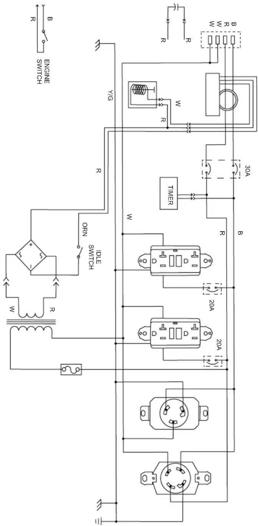
SCGH8500
| ORANGEON | |
| YELLOW/GREENY/2 | |
| WHITEW | |
| BLACKB | |
| RED |
flowchart
graph TD
    A["Power Source"] --> B["AC Source"]
    B --> C["Transformer 1"]
    B --> D["Transformer 2"]
    B --> E["Transformer 3"]
    C --> F["Inductor"]
    D --> G["IGC"]
    E --> H["IGC"]
    F --> I["Motor"]
    G --> J["Motor"]
    H --> K["Motor"]
    I --> L["Switch"]
    J --> M["Switch"]
    K --> N["ON"]
    L --> O["ON"]
    M --> P["ON"]
    N --> Q["ON"]
    O --> R["ON"]
    P --> S["ON"]
    Q --> T["ON"]
    R --> U["Timer"]
    S --> V["Timer"]
    T --> W["Timer"]
    U --> X["30A"]
    V --> Y["30A"]
    W --> Z["30A"]
    X --> AA["30A"]
    Y --> AB["30A"]
    Z --> AC["30A"]
    AA --> AD["30A"]
    AB --> AE["30A"]
    AC --> AF["30A"]
    AD --> AG["30A"]
    AE --> AH["30A"]
    AF --> AI["30A"]
    AG --> AJ["30A"]
    AH --> AK["30A"]
    AI --> AL["30A"]
    AJ --> AM["30A"]
    AK --> AN["30A"]
    AL --> AO["30A"]
    AM --> AP["30A"]
    AN --> AQ["30A"]
    AO --> AR["30A"]
    AP --> AS["30A"]
    AQ --> AT["30A"]
    AR --> AU["30A"]
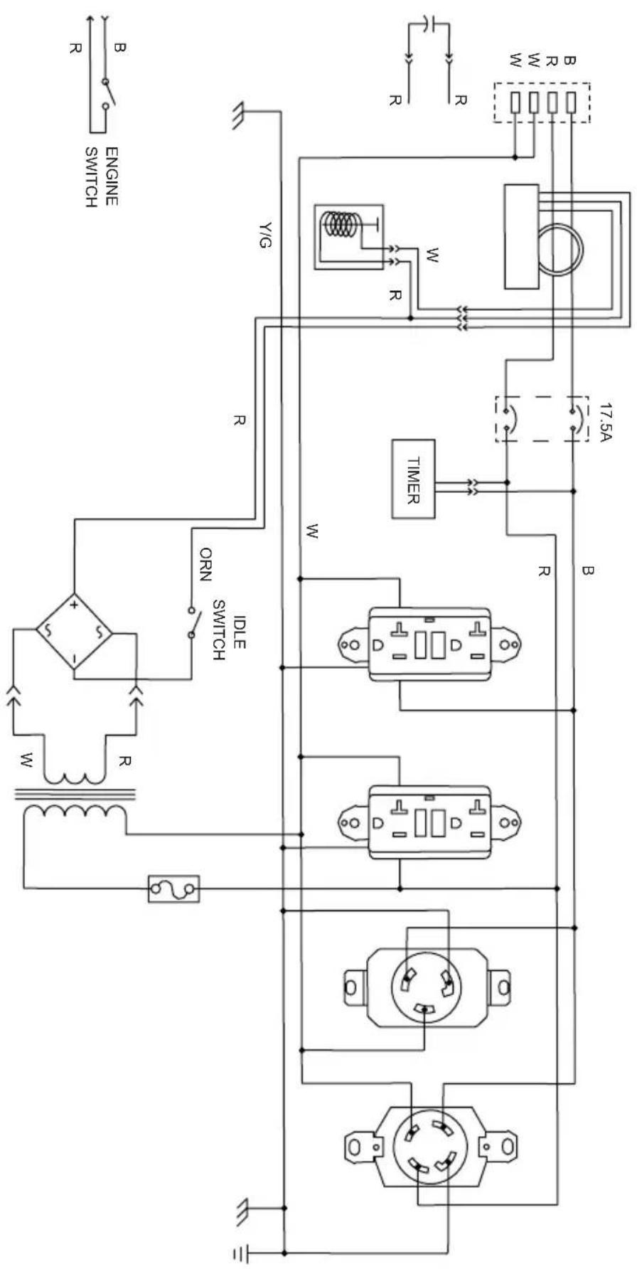
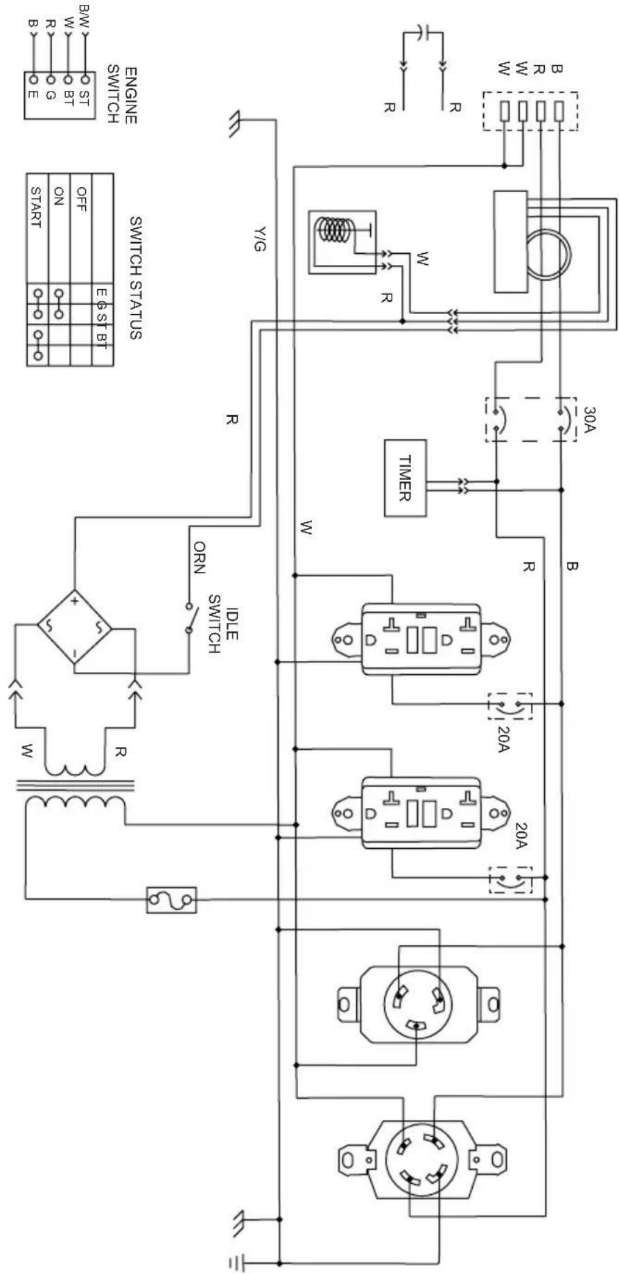
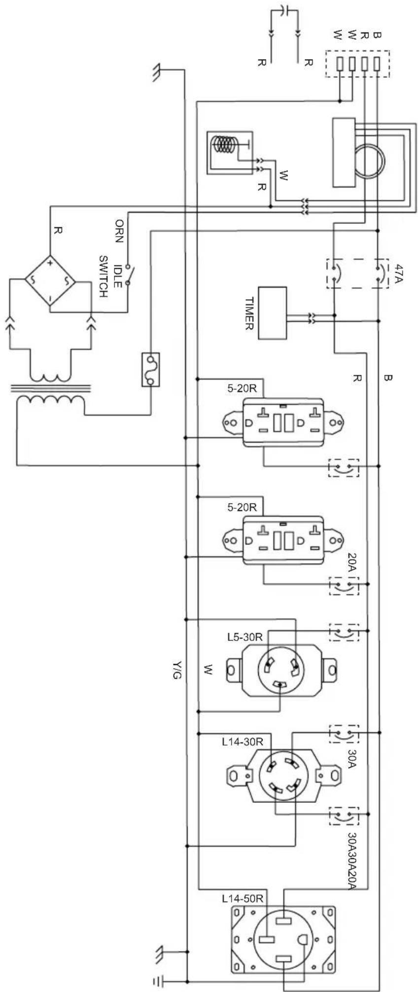
SCGH8500E
| BLACK/WHITE/B/M | |
| R | RED |
| BLACKB | |
| WHITE | |
| YELLOW/GREEN/Y/G | |
| ORANGEORN |
flowchart
graph TD
    A["Power Supply"] --> B["Transformer"]
    B --> C["Inductor"]
    C --> D["Switch"]
    D --> E["ON/OFF/START/SW"]
    E --> F["Control Signals: START, ON, OFF, BT, S1, BT, E6ST, EN"]
    G["Switch Status"] --> H["Timer"]
    H --> I["20A"]
    H --> J["20A"]
    H --> K["20A"]
    L["Engine Switch"] --> M["BMW"]
    M --> N["E"]
    N --> O["B"]
    O --> P["W"]
    P --> Q["R"]
    Q --> R["B"]
    R --> S["W"]
    S --> T["R"]
    T --> U["W"]
    U --> V["R"]
    V --> W["W"]
    W --> X["R"]
    X --> Y["B"]
    Y --> Z["W"]
    Z --> AA["R"]
    AA --> AB["W"]
    AB --> AC["R"]
    AC --> AD["W"]
    AD --> AE["R"]
    AE --> AF["W"]
    AF --> AG["R"]
    AG --> AH["W"]
    AH --> AI["R"]
    AI --> AJ["W"]
    AJ --> AK["R"]
    AK --> AL["W"]
    AL --> AM["R"]
    AM --> AN["W"]
    AN --> AO["R"]
SCGH10000E
| BLACK/WHITE/B/M | |
| R | RED |
| BLACKB | |
| WHITE | |
| YELLOW/GREENY/C | |
| ORANGEON |
Model Number: SCGH5500 / Item Number: 70053
| Generator Set Frequency | ency 60hz | |
| Voltage 120v / 240v | ||
| Phase Single | ||
| Running Watts* 4500 | watts | |
| Starting Watts 5500 watts | ||
| Power Factor 1.0 | ||
| Insulation Rate Class “F” (105°C / 40°C) | ||
| Fuel Capacity 7.9 Gallons / 30 Liters | ||
| Engine Specifications | Engine Model Honda | GX270 |
| Displacement 270cc | ||
| Start Style Recoil | ||
| Oil Capacity 1.16 Quarts / 1.1 Liters |
Model Number: SCGH8500 / Item Number: 70054
| Generator Set Frequency | 60hz | |
| Voltage 120v / 240v | ||
| Phase Single | ||
| Running Watts* 7000 watts | ||
| Starting Watts 8500 watts | ||
| Power Factor 1.0 | ||
| Insulation Rate Class “F” (105°C / 40°C) | ||
| Fuel Capacity 7.9 Gallons / 30 Liters | ||
| Engine Specifications | Engine Model Honda | GX390 |
| Displacement 389cc | ||
| Start Style Recoil | ||
| Oil Capacity 1.16 Quarts / 1.1 Liters | ||
*Generator per Portable Generator Manufacturers' Association (PGMA) standard ANSI / PGMAG6300-2015, Safety and Performance of Portable Generators
Model Number: SCGH8500E / Item Number: 70055
| Generator Set Frequency | ency 60hz | |
| Voltage 120v / 240v | ||
| Phase Single | ||
| Running Watts* 7000 | watts | |
| Starting Watts 8500 watts | ||
| Power Factor 1.0 | ||
| Insulation Rate Class | “F” (105°C / 40°C) | |
| Fuel Capacity 7.9 Gallons / 30 Liters | ||
| Engine Specifications | Engine Model Honda | GX390 |
| Displacement 389cc | ||
| Start Style Electric & Recoil | ||
| Oil Capacity 1.16 Quarts / 1.1 Liters |
Model Number: SCGH10000E / Item Number: 70098
| Generator Set Frequency | 60hz | |
| Voltage 120v / 240v | ||
| Phase Single | ||
| Running Watts* 10000 watts | ||
| Starting Watts 13000 watts | ||
| Power Factor 1.0 | ||
| Insulation Rate Class “F” (105°C / 40°C) | ||
| Fuel Capacity 8.5 Gallons / 32 Liters | ||
| Engine Specifications | Engine Model Honda | |
| Displacement See engine manual for specification | ||
| Start Style Electric | ||
| Oil Capacity 1.79 Quarts / 1.7 Liters | ||
*Generator per Portable Generator Manufacturers' Association (PGMA) standard ANSI / PGMAG6300-2015, Safety and Performance of Portable Generators
THIS PAGE WAS INTENTIONALLY LEFT BLANK
THIS PAGE WAS INTENTIONALLY LEFT BLANK
THIS PAGE WAS INTENTIONALLY LEFT BLANK


READ THIS MANUAL CAREFULLY BEFORE OPERATION
Failure to follow the instructions and safety precautions in this manual can result in property damage, serious injury and/or death.
SAVE THIS MANUAL FOR FUTURE REFERENCE

GÉNÉRATRICE
GUIDE D'UTILISATION ET D'ENTRETIEN
natural_image
Technical line drawing of a portable electricity generator with visible fan, wheels, and control panel (no text or labels)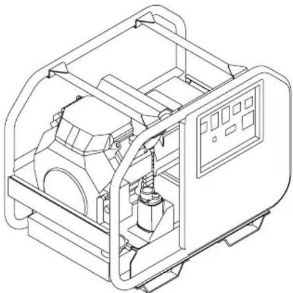
natural_image
Technical line drawing of an industrial machine with internal components and control panel (no text or symbols)
REGARDEZ AVANT DE POMPER!
natural_image
Technical line drawing of a mechanical housing or enclosure with three directional arrows pointing to internal components (no text or symbols)natural_image
Technical line drawing of a mechanical device interior with internal components and directional arrows (no text or symbols)SCGH5500, SCGH8500(E)
SCGH10000E
11
11
13
PANNEAUX DE COMMANDE
SCGH5500
SCGH8500
SCGH8500E
SCGH10000E
15
15
15
15
16
HOROMÈTRE
COMMANDE DU RALENTI
17
17
LISTE DE CONTRÔLE DE FONCTIONNEMENT
Emplacement
natural_image
Technical illustration of a mechanical device with wheels and a downward arrow indicating motion (no text or symbols)

AVERTISSEMENT:
natural_image
Technical line drawing of a mechanical assembly with two components connected by a rod (no text or symbols present)SCGH10000E
SCGH5500, SCGH8500(E)
SCGH8500
SCGH8500E
flowchart
graph LR
    A["ON/OFF"] --> B["OU"]
    B --> C["ON/OFF"]
COMMUTATEUR DE COMMANDE DE RALENTI
Emplacement
SCGH5500, SCGH8500(E)
natural_image
Simple line drawing of a rounded rectangular object with a protruding top and a horizontal line extending from its right side (no text or symbols)SCGH5500
SCGH8500(E)
Niveau de
carburant
maximum
natural_image
Simple line drawing of a rectangular block with an eraser extending from its top edge (no text or symbols)SCGH10000E
DÉMARRAGE DU MOTEUR
natural_image
Diagram of an electrical outlet plug with a switch and two outlets, showing a right-pointing arrow (no text or symbols)natural_image
Simple line drawing of a hand holding a tool with multiple arrows pointing outward (no text or symbols)- Allow the engine to warm up and the idle to stabilize before connecting any devices or turning the idle control switch on.
BRANCHEMENT DES APPAREILS

ÉLECTROCUTION
natural_image
Electrical plug symbol with no accompanying text or labels
Épissé
Enroulé

natural_image
Pure diagram of a coiled cable with two connectors, no text or symbols present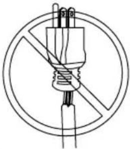
natural_image
Simple line drawing of a plug with a diagonal line crossing through it, enclosed in a circle (no text or symbols)Effiloché
Surchargé
natural_image
Diagram of a mechanical device with no visible text or symbols, enclosed in a circle (no readable text or symbols)natural_image
Diagram of an electrical outlet plug with a socket and terminal, showing a rightward arrow (no text or symbols)natural_image
Technical line drawing of a portable gas generator with visible blades and housing (no text or labels)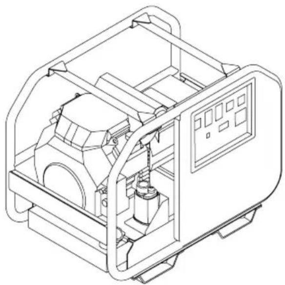
natural_image
Technical line drawing of an industrial machine with internal components and control panel (no text or symbols)
MIRA ANTES DE BOMBEAR!
natural_image
Technical line drawing of a mechanical housing or enclosure with three directional arrows pointing to internal components (no text or symbols)SCGH10000E
natural_image
Technical line drawing of a mechanical device interior with internal components and mounting brackets (no text or symbols)Model Data Decals Model Data Decal
SCGH5500, SCGH8500(E)
11
1
13
TABLEROS DE CONTROL
SCGH5500
15
SCGH8500
15
SCGH8500E
15
SCGH10000E
16
CONTADOR DE HORAS
17
CONTROL DE MARCHA EN VACÍO
17
SCGH5500, SCGH8500(E)
natural_image
Technical illustration of a mechanical device with wheels and a downward arrow indicating motion (no text or symbols)

natural_image
Technical line drawing of a mechanical assembly with two components connected by a rod (no text or symbols present)SCGH10000E
INTERRUPTOR DE CONTROL DE RALENTÍ
SCGH5500, SCGH8500(E)
natural_image
Diagram of a plug with two outlets and a handle, showing a right-pointing arrow (no text or symbols)flowchart
graph TD
    A["OFF"] --> B["Grid with O -"]
    B --> C["O"]
    C --> D["OFF"]
- Arranque el motor.
natural_image
Symbol of a crossed-out circle with an arrow indicating rotation or refresh (no text or numbers present)START
natural_image
Simple line drawing of a hand holding a screwdriver with three upward arrows (no text or symbols)natural_image
Electrical plug symbol with no accompanying text or labels
Empalmado
Enroscado

natural_image
Simple line drawing of a coiled cable with two connectors, no text or symbols present
natural_image
Simple line drawing of a plug with a diagonal line crossing through it, enclosed in a circle (no text or symbols)Raído
Sobrecargado

natural_image
Diagram of a mechanical or electrical component with no visible text, numbers, or symbolsnatural_image
Diagram of a plug with two outlets and a handle, showing a right-pointing arrow (no text or symbols)- Apague el motor.
MANTENIMIENTO

- READ THIS MANUAL CAREFULLY BEFORE OPERATION
- SAVE THIS MANUAL FOR FUTURE REFERENCE
- CALIFORNIA PROPOSITION 65 WARNING
- POLYCYCLIC AROMATIC HYDROCARBON WARNING
- SAVE THIS MANUAL FOR FUTURE USE
- SAFETY INSTRUCTIONS
- DISCLAIMERS
- ASSEMBLY
- COMPONENT LOCATION
- CONTROL PANELS
- HOUR METER
- IDLE CONTROL
- OPERATING CHECKLIST
- STARTING THE ENGINE
- 4
- 5
- 6
- 11
- 15
- 17
- 18
- 25
- CONNECTING DEVICES
- 27
- SHUTTING OFF THE ENGINE
- MAINTENANCE
- 30
- 31
- TROUBLESHOOTING
- 33
- STORAGE AND TRANSPORTATION
- 34
- WIRING DIAGRAMS
- 36
- SPECIFICATIONS
- 40
- READ THIS MANUAL BEFORE OPERATING
- ADDITIONAL INSTRUCTIONS
- HAZARD ALERT SYMBOLS
- Emission Information
- Air Induction System
- Fuel System
- Ignition System
- Exhaust System
- Special Requirements
- Unpacking
- Installing the Wheels - SCGH5500, SCGH8500(E)
- Assembling and Installing the Support Bracket
- Installing the Wheel set (optional)
- WARNING:
- Installing the Handle (optional)
- Connecting Battery (Electric Start Models Only)
- ACID
- BATTERY CONNECTIONS
- SCGH8500E
- SCGH10000E
- IDLE CONTROL (if equipped)
- Location
- TOXIC FUMES
- Operating Conditions
- UNTRAINED OPERATION
- HOT SURFACES
- MOVING PARTS
- Grounding
- ELECTROCUTION
- Connecting Generator to the Electrical System of a Building
- BACKFEEDING
- Checking the Engine Oil
- NOTICE
- SCGH5500, SCGH8500(E)
- Checking Fuel
- REFUELING
- OLD FUEL
- ALCOHOL BLENDS
- FUEL ADDITIVES
- ! CAUTION:©
- FUEL TANK PRESSURE
- GASOLINE STORAGE
- DO NOT OVERFILL FUEL TANK
- RAPID RETRACTION
- Electric Start Models Manual Start Models
- Ground Fault Circuit Interrupt (GFCI) (if equipped)
- Testing the GFCI receptacle(s)
- Connecting Electrical Devices
- FIRE HAZARD
- Generator Load Capacity
- Generator Load Chart
- Electric Start Models
- Manual Start Models
- Generator Maintenance
- Engine Maintenance
- Cleaning
- Battery Maintenance (Electric Start Models Only)
- EXPLOSIVE GAS
- Engine Idle Adjustment
- IDLE ADJUSTMENT
- MODIFICATION
- Storing for Two Months or Less
- Storing for More Than Two Months
- Transportation
- SCGH8500
- THIS PAGE WAS INTENTIONALLY LEFT BLANK
- GÉNÉRATRICE
- GUIDE D'UTILISATION ET D'ENTRETIEN
- PANNEAUX DE COMMANDE
- HOROMÈTRE
- COMMANDE DU RALENTI
- LISTE DE CONTRÔLE DE FONCTIONNEMENT
- AVERTISSEMENT:
- Emplacement
- DÉMARRAGE DU MOTEUR
- BRANCHEMENT DES APPAREILS
- ÉLECTROCUTION
- MIRA ANTES DE BOMBEAR!
- TABLEROS DE CONTROL
- CONTADOR DE HORAS
- CONTROL DE MARCHA EN VACÍO
- MANTENIMIENTO
Brand : Simpson
Model : SCGH8500E
Category : Generator